Analysis of Faults in Three Phase Induction Motor using...
14
1 International Journal of Control Theory and Applications Analysis of Faults in Three Phase Induction Motor using Neuro Fuzzy Logic and Wavelet Transformation Jayanthi Dhandapani and R. Chandralekha Department of Electrical and Electronics Engineering, Vel Tech Multi Tech, Avadi, Chennai, Tamil Nadu, India E-mails: [email protected]; [email protected] Abstract: Induction machines are one of the larger rotating parts in all type of the organization and is the one which is most used in major electrical machines. So, identification of defects in the Induction motors is very vital to increase the actions of the motor, avoid the loss of the production and also operation cost reduction. Vibration and current analysis and measurement process are used for this method. Here, the proposed method uses diagnosis of stray flux nearby electrical machines different positions. The main aim of the proposed method is to identify the failure in the electrical machines by means of analysis of vibration. The goal of the proposal is to present a new technique to find the rotor bar failure. The Neuro Fuzzy Logic method is used to focus the study on approximation signals from the wavelet decomposition. This paper deals with the fault identification of Three Phase Induction Motor. Keywords: Electric Machines, fault detection, location identification, diagnosis, Induction motors, Wavelet Transform Statistical analysis and Neuro Fuzzy Logic. 1. INTRODUCTION In Industry Industrial process are mainly done by Induction Motor. Motor failure causes financial losses. In the paper [20] machine monitoring and their preventive techniques are given. The Induction Motor power-weight ratio and the robustness show more advantages. Hence, the Induction Motors are widely used. To reduce the operational costs and production improvement for Electrical machines are in greater demand. For rotor fault diagnosis [19] many methods are proposed. This paper presents the condition monitoring strategy which makes the accurate and reliable measurements for the faults in Induction Machine. In this modern industrial world, millions of motors are used in all types of process. Any shutdown due to induction motors will indicate the fault in the induction motor. Fault of the motor can be possible to find out means to schedule an orderly shutdown with efficient usage of material and labor. In order to find out the system faults automatic condition monitoring and detection are needed. Various types of motor fault detection are available. These types of algorithms are classified into domains like phase, analysis of spectral and ideal techniques. Current spectrum analysis, vibration analysis and thermal analysis of various condition monitoring [13] for various types of motor failures has been given.
-
Upload
nguyenkhanh -
Category
Documents
-
view
236 -
download
0
Transcript of Analysis of Faults in Three Phase Induction Motor using...

1 International Journal of Control Theory and Applications
Analysis of Faults in Three Phase Induction Motor using Neuro Fuzzy Logic and Wavelet Transformation
Analysis of Faults in Three Phase Induction Motor using Neuro FuzzyLogic and Wavelet Transformation
Jayanthi Dhandapani and R. Chandralekha
Department of Electrical and Electronics Engineering, Vel Tech Multi Tech, Avadi, Chennai, Tamil Nadu, IndiaE-mails: [email protected]; [email protected]
Abstract: Induction machines are one of the larger rotating parts in all type of the organization and is the one whichis most used in major electrical machines. So, identification of defects in the Induction motors is very vital to increasethe actions of the motor, avoid the loss of the production and also operation cost reduction. Vibration and currentanalysis and measurement process are used for this method. Here, the proposed method uses diagnosis of stray fluxnearby electrical machines different positions. The main aim of the proposed method is to identify the failure in theelectrical machines by means of analysis of vibration. The goal of the proposal is to present a new technique to findthe rotor bar failure. The Neuro Fuzzy Logic method is used to focus the study on approximation signals from thewavelet decomposition. This paper deals with the fault identification of Three Phase Induction Motor.
Keywords: Electric Machines, fault detection, location identification, diagnosis, Induction motors, Wavelet TransformStatistical analysis and Neuro Fuzzy Logic.
1. INTRODUCTION
In Industry Industrial process are mainly done by Induction Motor. Motor failure causes financial losses. In thepaper [20] machine monitoring and their preventive techniques are given.
The Induction Motor power-weight ratio and the robustness show more advantages. Hence, the InductionMotors are widely used. To reduce the operational costs and production improvement for Electrical machinesare in greater demand. For rotor fault diagnosis [19] many methods are proposed. This paper presents the conditionmonitoring strategy which makes the accurate and reliable measurements for the faults in Induction Machine.
In this modern industrial world, millions of motors are used in all types of process. Any shutdown due toinduction motors will indicate the fault in the induction motor. Fault of the motor can be possible to find outmeans to schedule an orderly shutdown with efficient usage of material and labor.
In order to find out the system faults automatic condition monitoring and detection are needed. Varioustypes of motor fault detection are available. These types of algorithms are classified into domains like phase,analysis of spectral and ideal techniques. Current spectrum analysis, vibration analysis and thermal analysis ofvarious condition monitoring [13] for various types of motor failures has been given.

International Journal of Control Theory and Applications 2
Jayanthi Dhandapani and R. Chandralekha
Statistical analysis of the stray flux calculation [18] is given in this paper in order to find out the faults in theInduction Motors.
2. LITERATURE SURVEY ON FAULT DETECTION
In this survey flux leakage detection are presented.
Shorted stator winding turns, damaged or broken rotor bars, bearing faults are presented in the three phaseInduction motors, these faults are carried out by the flux measurements [17] on a three-phase IM. Externalsearch coils with 200 turns length which is similar to the machine axial length is described and the width of themachine equal to the pole pitches. These search coils are mounted on the inactivated end .This coil is describedin [17] which can be matched probed for our research, since both are large range machine size external coil. In[17] other than that sensor description are given, that is the sensor sensitivity is hard to diagnose .The experimentalmeasurement by spectral analysis shows:
• Fundamental increase in the magnitude (approximately 10 times) due to effect of inter-turn short circuit.
• When the motor is in full load condition broken rotor bars features constituents visible in the fluxspectrum. Three broken bars state is findable during half-load and no-load.
• Bearing and the static eccentricity cannot be detectable by this coil, only dynamic eccentricity isdetectable.
In [15] and [16] the period analysis of the flux information can be presented. To detect stator windingfailure [15],[1],[2],broken rotor bars [3],[4] and to check the gearbox in the reference papers authors used a strayflux sensor. This sensor turns kept adjacent to the motor body. In [15] the flux sensor has been kept equivalent tothe horizontal axis of the machine and in [16] it is right angle to the body of the machine. The diameter has beenkept very low from the full length of the motor in order to detect the flux. Coil terminals voltage is related to theplagiaristic of the flux leakage; hence it has a high frequency and low magnitude. Flux sensor terminals areconnected to the changing gain amplifier. For the spectrum analysis the accurate range of bandwidth frequenciesare set by means of low-pass anti-aliasing filter. In [15] motor current signature analysis (MCSA) techniquestator fault detection carried out on squirrel cage IM .In [10] the machine is verified by the stray flux sensorwhich is equivalently placed before.in [3] rotor failure have been verified for broken rotor bars around thesupply frequency. After the disconnection of supply the broken rotor bars have been detected.
In [14] nearer to the Machine frame “C” type flux device are placed. Broken rotor bars will be finding outby this process. The increased amplitude with the slip has been identified by means of flux is used as a detectingvariable. Rotor failure can be detected by stray signals and current. Rotor is protected by the Stator which is ashield. This analysis is related to Conventional current analysis [13].
Decomposition of axial-radial are taken care in [12].To generate the axial flux in the axis of the motor isdone by stator and rotor cage ring current. Air-gap flux density image will be nothing but of radial field which isplaced on the plane right angle to the axis of the machine. It will be reduced by the external frame of the motor.Wound flux sensors are used to detect these fields. If the sensor is located equivalent to the machine body meansthe sensor is said to be radial otherwise it is axial. During normal condition of the machine the magnitude will below. Harmonic cannot be visible for a less slip and weal loads.
In the center of the stator frame divergent parameter will be determined by Tesla-meter in [11].It is acostlier method for small Induction Machines. Detection of dynamic eccentricity is easier. But the fault detectionof bearing is controversial, amplitude also very low.
Around electrical actuators stray flux are measured using GMR (giant magneto resistance). When thedevices undergone some resistance change GMR sensors are used. In [5] the process is applicable for rangedetection purpose and their linearity.

3 International Journal of Control Theory and Applications
Analysis of Faults in Three Phase Induction Motor using Neuro Fuzzy Logic and Wavelet Transformation
The detection of bearing fault is examined depends upon the vibration, temperature and current quantitiesin [8]. The damage occurs due to temperature differences, voltage and current instability. Neural networks areused to find out the machines performance, and the routines are related. Some recent control methods are discussedin [21-25].
3. PROPOSED FAULT DIAGNOSIS METHOD
The stray flux phenomenon has been discussed before [15].hence, the stray flux mechanisms study can be foundout [6].
Running condition of the motor describes the stray flux nature. Electrical Machines magnetic nature can bealtered based on the defect of the machine. Conditioned and unconditioned machine nature can be analyzed. Theaim of the proposal is to find out the failure of the machine by vibration analysis. Whenever the harmonicsincreases the shaking of the machine which describes the defect of the machine.
The planned technique is on statistical method which tells the organization atmosphere in a correct formatwith vigorous measurer [7].
The fault diagnosis technique is based on the vibration analysis. The Vibration under no load and full loadwill be sensed by using the flux sensor by keeping the sensor near the rotor bar of the motor in order to sense theleakage flux. The sensed magnetic field is recorded using SIGVIEW and then it is analyzed using MATLABwith the help of Wavelet Transformation using Neuro Fuzzy Logic. Neuro Fuzzy Logic have three ANFIStraining methodology they are Grid Partitioning, Subtractive Clustering and FCM Clustering. By using thismethodology RMSE values of both Healthy and Faulty nature of the machine will be compared. The comparisonshows the faulty location of the motor.
4. HARDWARE IMPLEMENTATION
By means of Neuro Fuzzy method the failure detection of three phase Induction machine can be easily measurable.This process will be done by means of toroidal sensor which is going to keep nearer to the working machine. Thissensor observes the flux leakages around a machine and is converted as a trend file. This output gives the exactfailure of the machine using MATLAB. By using MATLAB the signals are analyzed using Neuro Fuzzy methods.
By using the recorded signal files the data’s are splitted and the data’s are used for upcoming events. Thisdata’s are used in Genfis1 (Grid partitioning), Genfis 2(Subtractive Clustering), Genfis3 (FCM).
Figure 1: Hardware Setup

International Journal of Control Theory and Applications 4
Jayanthi Dhandapani and R. Chandralekha
For training ANFIS starting type FIS methods are used that is GENFIS1.Without gathering data on theGrid partitioning method the outputs are obtained. FIS first column is nothing but of input data and the lastcolumn will be a output data and it will be in a matrix format. Two connection functions (‘gbellmf’) used as aGENFIS1 input. Output will be one connection function called as ‘linear’.
In GENFIS2 input data sets and output data sets are isolated and FIS training done by subtractiveclustering.GENFIS2 gives the characteristics of the machine. SUBCLUST methods are used for abstraction, inthat many conditions are handled. Linear measurement methods are used to analyses the condition of the machine.
GENFIS1 and GENFIS2 methods are trained by ANFIS but this method get training by FIS method. Theprevious circumstances and moments are obtained by FCM clustering. Amalgam learning methodology is usedin ANFIS in order to find out the output using sugeno –FIS. To produce an ideal input and output, back propagationand least-squares gradient algorithm are used. By using this entire phenomenon the data’s are placed in a graph.
By using the above technique the machines abnormal phenomenon can be obtain. The toroidal sensors arekept nearer to the machine and the leakage fluxes are observed using sigview as a signal waveform. These waveformsare used as input for further measurement; this shows the defective parts of the machine, using Neuro Fuzzymethods by means of MATLAB. Time intervals are plotted in x-axis and the flux differences (Hertz) in y-axis.
The data which shows the Predefined input and output is known as Train data, that data usage as shown asGrid portioning method in Fig 2 and Fig 14 using neuro fuzzy scheme. Subtractive clustering method in Fig 6and Fig 18 using neuro Fuzzy mechanism and FCM clustering in Fig 10 and Fig 22 using Neuro Fuzzy Mechanism.
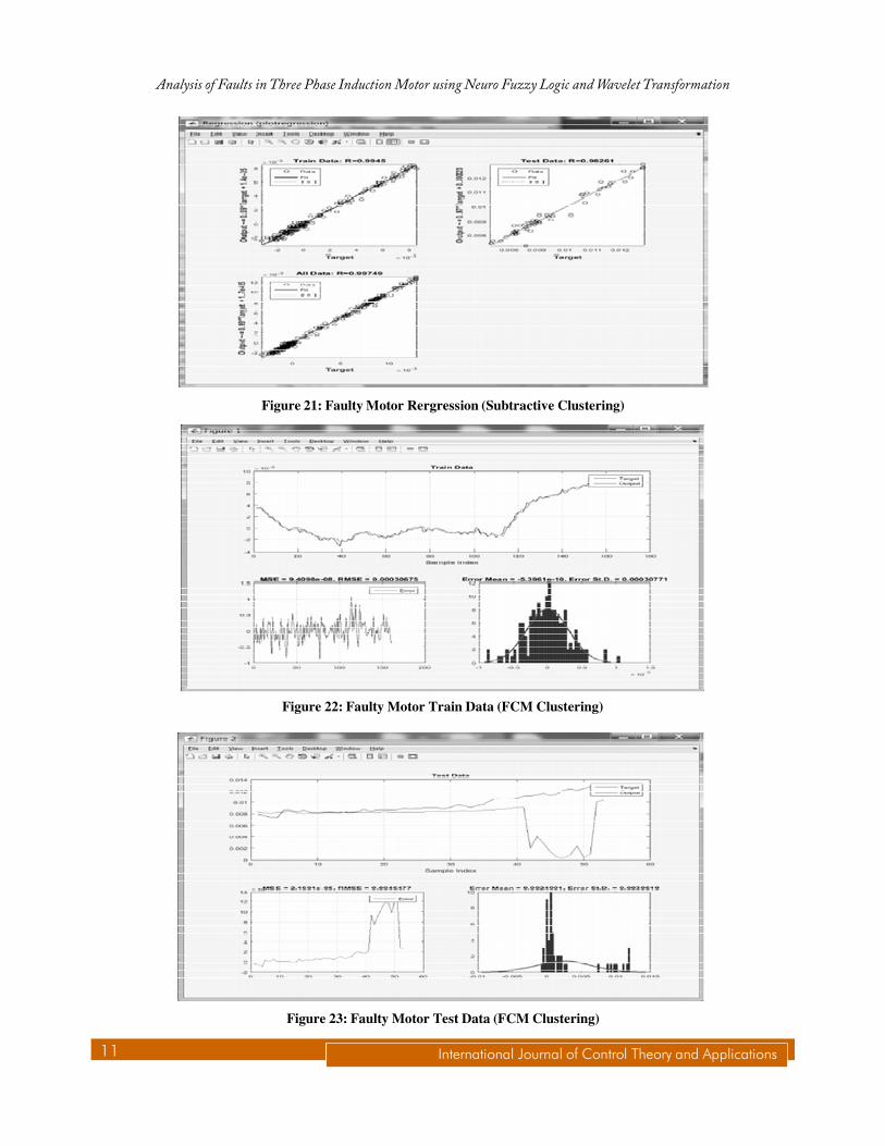
The data which is used to examine the methodology without any defined output is known as Test data. Thisdata usage has been shown as Grid portioning method in Fig 3 and Fig 15 using Neuro Fuzzy scheme. Subtractiveclustering method in Fig 7 and Fig 19 using neuro Fuzzy mechanism and FCM clustering in Fig 11 and Fig 23using Neuro Fuzzy Mechanism.
The data which is used to getting back the actual data based on the equipment is known as all data. The datausage has been shown as Grid portioning method in Fig 4 and Fig 16 using Neuro Fuzzy scheme. Subtractiveclustering method in Fig 8 and Fig 20 using neuro Fuzzy mechanism and FCM clustering in Fig 12 and Fig 24using Neuro Fuzzy Mechanism.
The data which is used to endorse the characteristics of the methodology using the exact data is known asRegression. The data usage has been shown as Grid portioning method in Fig 5 and Fig 17 using neuro fuzzyscheme. Subtractive clustering method in Fig 9 and Fig 21 using neuro Fuzzy mechanism and FCM clustering inFig 13 and Fig 25 using Neuro Fuzzy Mechanism.
Figure 2: Healthy Motor Train Data (Grid Partitioning)

5 International Journal of Control Theory and Applications
Analysis of Faults in Three Phase Induction Motor using Neuro Fuzzy Logic and Wavelet Transformation
Figure 3: Healthy Motor Test Data (Grid Partitioning)
Figure 4: Healthy Motor All Data (Grid Partitioning)
Figure 5: Healthy Motor Regression (Grid Partitioning)

International Journal of Control Theory and Applications 6
Jayanthi Dhandapani and R. Chandralekha
Figure 6: Healthy Motor Train Data (Subtractive Clustering)
Figure 7: Healthy Motor Test Data (Subtractive Clustering)
Figure 8: Healthy Motor All Data (Subtractive Clustering)

7 International Journal of Control Theory and Applications
Analysis of Faults in Three Phase Induction Motor using Neuro Fuzzy Logic and Wavelet Transformation
Figure 9: Healthy Motor Regression (Subtractive Clustering)
Figure 10: Healthy Motor Train Data (FCM Clustering)
Figure 11: Healthy Motor Test Data (FCM Clustering)

International Journal of Control Theory and Applications 8
Jayanthi Dhandapani and R. Chandralekha
Figure 12: Healthy Motor All Data (FCM Clustering)
Figure 13: Healthy Motor Regression (FCM Clustering)
Figure 14: Faulty Motor Train Data (Grid Partitioning)

9 International Journal of Control Theory and Applications
Analysis of Faults in Three Phase Induction Motor using Neuro Fuzzy Logic and Wavelet Transformation
Figure 15: Faulty Motor Test Data (Grid Partitioning)
Figure 16: Faulty Motor All Data (Grid Partitioning)
Figure 17: Faulty Motor Regression (Grid Partitioning)

International Journal of Control Theory and Applications 10
Jayanthi Dhandapani and R. Chandralekha
Figure 18: Faulty Motor Train Data (Subtractive Clustering)
Figure 19: Faulty Motor Test Data (Subtractive Clustering)
Figure 20: Faulty Motor All Data (Subtractive Clustering)
11 International Journal of Control Theory and Applications
Analysis of Faults in Three Phase Induction Motor using Neuro Fuzzy Logic and Wavelet Transformation
Figure 21: Faulty Motor Rergression (Subtractive Clustering)
Figure 22: Faulty Motor Train Data (FCM Clustering)
Figure 23: Faulty Motor Test Data (FCM Clustering)

International Journal of Control Theory and Applications 12
Jayanthi Dhandapani and R. Chandralekha
Figure 24: Faulty Motor All Data (FCM Clustering)
Figure 25: Faulty Motor Regression (FCM Clustering)
5. COMPARISON BETWEEN HEALTHY AND FAULTY MOTOR
4
3
2
1
00 25 50 75 100 125 150 175 200
RMSE Healthy
RMSE... RMSE...
Value
RMSE Healthy
RMSE Faulty

13 International Journal of Control Theory and Applications
Analysis of Faults in Three Phase Induction Motor using Neuro Fuzzy Logic and Wavelet Transformation
The motor vibrations were analyzed using Neuro Fuzzy Logic and the data has been plotted in a graph format.The graph explains the faulty condition and the healthy condition of the motor. The graph provides the RMSEvalue changes by time. Time taken has been used as X-axis and RMSE values have been used in Y-axis. The risein the RMSE values between 0 and 25 seconds is during the starting of the motor. The deviation between theRMSE values of Healthy and Faulty motor has been shown in the graph. The faulty motor has high RMSE valuessince the faulty motor has high vibration than the healthy motor.
6. CONCLUSION
The discussing procedure requires “Normal references” for exact dimensions assessments for the machine. Thisanalyzed data’s must be grouped together currently or it must be during its starting condition of the machine orit should be matched with the starting condition of the motor for better bearing quality control.
The toroidal sensor used for this process is due to its working nature, size, cost and its availability and itsamendment towards the power changes. These sensors are used to test the machine during normal and abnormalbehavior and it is required to calculate the leakage flux in various places near the machine in order to find out theexact location of the fault in the Induction Motor.
The rotor bar failure and the fault location of the motor due to electro-mechanical nature are accuratelyobtained by the process and this process gives the improved version of motor conditions when compared to otherprocess.
REFERENCES
[1] H. Henao, G.A. Capolino and C.S. Martis, “On the stray flux analysis for the detection of the three-phase induction machinefaults,” in Conf. Rec. 38th IEEE IAS Annual Meeting, vol. 2, 1368-1373, 2003.
[2] A. Yazidi, D. Thailly, H. Henao, R. Romary, G.A. Capolino, and J.F. Brudny, “Detection of stator short-circuit in inductionmachines using an external leakage flux sensor,” in Proc. IEEE ICIT, Hammamet, Tunisia, 166-169, 2004.
[3] A. Yazidi, H. Henao, and G.A Capolino, “Broken rotor bars fault detection in squirrel cage induction machines,” in Proc.IEEE IEMDC, San Antonio, USA, 741-747, 2005.
[4] S.H. Kia, H. Henao, G.A. Capolino and C.S.Martis, “Induction machine broken bars fault detection using stray flux aftersupply disconnection,” in Proc. IEEE IECON, Paris, 1498-1503, 2006.
[5] M. Brela, N. Kassim, and J. Franke, “Characterization of magnetic actuators, by measuring of magnetic stray fields withGMR-sensors,” in Proc. 3rd Int. EDPC, Nuremberg, Germany, 1-7, 2013.
[6] R.R. Schoen, T.G. Habetler, F. Kamran, and R.G. Bartheld, “Motor bearing damage detection using stator current monitoring,”IEEE Transactions on Industry Applications, 31 (6), 1274-1279, 1995.
[7] C. Harlisca, L. Szabo, L. Forisni, and A. Albini, “Diagnosis of rolling bearing faults in electric machines through straymagnetic flux monitoring,” in Proc. Int. Symp. ATEE, Bucuresti, Romania, 2013.
[8] M.S. Yilmaz and Emine Ayaz “Adaptive neuro-fuzzy inference system for bearing fault detection in induction motorsusing temperature, current, vibration data,” EUROCON-2009, IEEE Conference, May 18-23, 2009.
[9] R.Chandralekha, D. Nivea and T.Geethapriya, “The energy efficient induction motor drive using seven level multilevelinverter,” Journal of Electrical Engineering, 14 (1), 1-8, 2014.
[10] R.Chandralekha, P. Princy and R. Meenakshi, “Implementation of piccolo dsp based fault monitoring system for singlephase induction motor,” Journal of Electrical Engineering , 15 (4), 118-125, 2015
[11] E. Ayaz, A. Oztruk, and S. Seker, “Continuous Wavelet Transform for bearing damage detection in electric motors,” inProc. IEEE MELECON, Malaga, Spain, 1130-1133, 2006.
[12] K.S. Gaeid, H.W. Ping, M.K. Masood, and L. Szabo, “Survey of wavelet fault diagnosis and tolerant of induction machineswith case study,” Intern. Rev. of Elect. Eng. (IREE), 7 (3), 4437-4457, 2012.

International Journal of Control Theory and Applications 14
Jayanthi Dhandapani and R. Chandralekha
[13] O. Vitec, M. Janda, V. Hajek and P. Bauer, “Detection of eccentricity and bearing faults using stray flux monitoring,” inProc. IEEE SDEMPED, Bologna, Italy, pp. 456-461, 2011.
[14] A. Cebank, R. Pusca, and R. Romary, “Eccentricity and broken rotor bars faults – Effects on the external axial field,” inProc. IEEE ICEM, Rom, Italy, 1-6, 2010.
[15] R. Romary, R. Corton, D. Thailly, and J.F. Brudny, “Induction machine fault diagnosis using an external radial fluxsensor,” European Physical Journal– Applied Physics, 32 (2), 125-132, 2005.
[16] J.M.B. Siau, A.L. Graff, W.L. Soong, and N. Ertugrul, “Broken bar detection in induction motors using current and fluxspectral analysis,” Australian Journal of Electrical and Electronics Engineering, 1, 171-178, 2004.
[17] A. Bellini, S. Concari, G. Franceschini, C. Tassoni, and A. Toscani, “Vibrations, currents and stray flux signals to assessinduction motor rotor condition,” in Proc. IEEE IECON, Paris, France, 4963-4968, 2006.
[18] M. Blodt, P. Granjon, B. Raison and G. Rostaing, “Models for bearing damage detection in induction motors using statorcurrent monitoring,” IEEE Transactions on Industrial Electronics, 55 (4), 1813-1822, 2008.
[19] A. Garcia-Perez, R.D.J. Romero-Troncoso, E. Cabal-Yepez and R.A. Osornio-Rios, “The application of high-resolutionspectral analysis for identifying multiple combined faults in induction motors,” IEEE Transactions on Industrial Electronics,58 (5), 2002-2010, 2011.
[20] P. Zhang, Y. Du, T.G. Habetler and B. Lu, “A survey of condition monitoring and protection methods for medium-voltageinduction motors,” IEEE Transactions on Industry Applications, 47 (1), 34-46, 2011.
[21] V.T. Pham, S. Jafari, C. Volos, A. Giakoumis, S. Vaidyanathan and T. Kapitaniak, “A chaotic system with equilibrialocated on the rounded square loop and its circuit implementation,” IEEE Transactions on Circuits and Systems-II: ExpressBriefs, 63 (9), 2016.
[22] S. Vaidyanathan and S. Sampath, “Anti-synchronisation of identical chaotic systems via novel sliding control and itsapplication to a novel chaotic system,” International Journal of Modelling, Identification and Control, 27 (1), 3-13, 2017.
[23] S. Vaidyanathan, K. Madhavan and B.A. Idowu, “Backstepping control design for the adaptive stabilization andsynchronization of the Pandey jerk chaotic system with unknown parameters,” International Journal of Control Theoryand Applications, 9 (1), 299-319, 2016.
[24] R.K. Goyal, S. Kaushal and S. Vaidyanathan, “Fuzzy AHP for control of data transmission by network selection inheterogeneous wireless networks,” International Journal of Control Theory and Applications, 9 (1), 133-140, 2016.
[25] C.K. Volos, D. Prousalis, I.M. Kyprianidis, I. Stouboulos, S. Vaidyanathan and V.T. Pham, “Synchronization and anti-synchronization of coupled Hindmarsh-Rose neuron models,” International Journal of Control Theory and Applications,9 (1), 101-114, 2016.