Quick Path Planning Based on Shortest Path Algorithm for ...
Upload
nguyenkietCategory
view
219download
1
Research Article
May 2015
© 2015, IJERMT All Rights Reserved Page | 119
International Journal of
Emerging Research in Management &Technology
ISSN: 2278-9359 (Volume-4, Issue-5)
Analysis and Implementation of Shared Path Protection, Computation and
Provisioning system for SONET/SDH Network 1Deepak Dhadwal,
2Ashok Arora,
3V R Singh
1Research Scholar, Manav Rachna International University, Haryana, India
2Proffessor, Manav Rachna International University, Haryana, India
3Director, PDM College of Engineering, Haryana, India
Abstract—
andwidth Requirement is one of the critical issue in the current environment of high speed communications.
This also effects for the network operators and service providers in terms of communication business. That is
the reason which forces the Engineers to generated different types of services like PDH, SONET/SDH, WDM,
DWDM, ATM, DSL etc. There is also need of providing different QoS for different users. This directly affects the
revenue of Service providers.. In this paper, Shared path protection studied, analyzed and implemented. An optimized
shared protection algorithm is also discussed and implemented.
IndexTerms—SONET/SDH, Path protection algorithm, bandwidth protection algorithm, DWDM, ATM.
I. INTRODUCTION When data is transmitted over a communication medium, a number of things must be provided on the link,
including framing of the data, error checking and the ability to manage the link. For For optical communications these
functions have been standardized by the ANSI T1X1.5 committee as Synchronous Optical Networking (SONET) and by
the ITU as Synchronous Digital Hierarchy (SDH). This paper attempts to describe how SONET/SDH works, down to the
octet level.
For a great many years, telephone calls were handled in the analog domain. Long distance calls were routed over
twisted pair, coaxial cable, or analog microwave between major switching offices.
In 1962, AT&T began installing DS-1 T-carrier services between long distance switching centers. Basically, these
were channel banks2 which took 24 analog telephone circuits, converted them to digital and then transmitted them over
copper to the other switching center, where they were converted back to analog. This worked very well – it reduced the
number of copper circuits required between switching centers and improved the quality of the telephone calls (less noise
and crosstalk).
Synchronous optical Network (SONET) offers cost-effective transport both in the access area and core of the
network. For instance telephone or data switches rely on SONET transport for interconnection. The optical layer provides
the foundation of transport services for both metro and long-haul applications. It also directly supports data services. The
optical layer is now evolving to provide the same level of sophistication that has been achieved with synchronous
transmission, such as
performance monitoring and network resilience. Till that discussion we can see the SONET/SDH architecture which has
been shown in Fig. 2.
Fig. 2: SONET/SDH Architecture
we can analyse the OC-N level signals and STS frames, as the frame structure knowledge is very much important as
we said it’s a standard. So according to the SONET standards, which type of the frame structures are here to
communicate among the nodes of the communication elements (in this case the telecommunication hubs). Analysis of
virtual concatenation and VTs has been done for low data rate signals. Analysis of Ethernet over SONET, Packet over
SONET is also discussed and analyzed.
B
Dhadwal et al., International Journal of Emerging Research in Management &Technology
ISSN: 2278-9359 (Volume-4, Issue-5)
© 2015, IJERMT All Rights Reserved Page | 120
1.2 ANALYSIS OF STS-N FRAME
STS stands for synchronous transport signal. The STS –N frame is terms of electrical signal after interleaving the
standards stands for the optical carrier OC-N. Here N stands for level of STS and OC frames. Table 1 shows the
SONET/SDH frame structure.
TABLE I STS-N FRAME RATES
S
ONET
Frame
SD
H
FRAM
E
LINE
RATE(Mbp
s)
S
PE
(Mbps
)
TRAN
SPORT OH
(Mbps)
S
TS-1
No
ne
51.84 5
0.112
1.728
S
TS-3
ST
M-1
155.52 1
50.336
5.184
S
TS-12
ST
M-4
622.08 6
01.344
20.736
S
TS-48
ST
M-16
2,488.3
2
2,
405.37
6
84.672
S
TS-192
ST
M-64
9,953.2
8
9
621.50
4
331.77
6
S
TS-168
ST
M-256
39,813.
12
3
8,486.
016
1,327.1
04
More about SONET frame structures are discussed as follows:
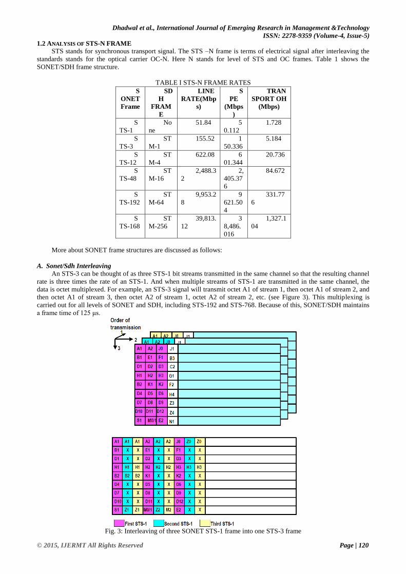
A. Sonet/Sdh Interleaving
An STS-3 can be thought of as three STS-1 bit streams transmitted in the same channel so that the resulting channel
rate is three times the rate of an STS-1. And when multiple streams of STS-1 are transmitted in the same channel, the
data is octet multiplexed. For example, an STS-3 signal will transmit octet A1 of stream 1, then octet A1 of stream 2, and
then octet A1 of stream 3, then octet A2 of stream 1, octet A2 of stream 2, etc. (see Figure 3). This multiplexing is
carried out for all levels of SONET and SDH, including STS-192 and STS-768. Because of this, SONET/SDH maintains
a frame time of 125 μs.
Fig. 3: Interleaving of three SONET STS-1 frame into one STS-3 frame

Dhadwal et al., International Journal of Emerging Research in Management &Technology
ISSN: 2278-9359 (Volume-4, Issue-5)
© 2015, IJERMT All Rights Reserved Page | 121
Let’s look at this a bit closer. Figure 3 shows an STS-3 frame created from the interleaving shown. It consists of 9
rows and 270 columns, of which 27 columns are overhead. Now, let’s zoom in closer on this overhead. We see that the
first three octets in the first row are all A1 octets. This is because we took three frames and octet interleaved them. So we
took the first octet from the first STS-1 frame (which is an A1 octet), then we took the first octet from the second STS-1
frame (which is an A1 octet), and then we took the first octet from the third STS-1 frame (which is also an A1 octet).
Then we took the second octet from the first frame (which is an A2 octet), then the second octet from the second frame
(which is anA2 octet), and finally the second octet from the third frame (which is also an A2 octet), etc.
For such a frame we can define a simple programming as follows:
for (row = 1; row <= 9; row++)
for (column = 1; column <= 90; column++)
for (bit = 1; bit <= 8; bit ++)
/* bit 1 is the most significant bit */
/* and bit 8 is the least significant bit */
bitTransmit = STSFrame[row][column][bit];
In spite of discussing about the whole transport overhead here we can discuss only too much important special
octets which effects the transmission synchronization and other aspects need for the SONET/SDH architecture
II. SHARED PATH COMPUTATION AND PROTECTION
The backup path may either be path based (i.e. from the source to destination node) or link based (i.e. from a node
preceding the failure to a node succeeding the failure) So, paradigms of survivability can broadly be classified using four
criteria: Execution, Computation, Rerouting and Resources.
A. Execution
Survivability scheme may be employed by a network that is executed and controlled either centrally or in a
distributed manner. A central controller involved by the centralized scheme, where a source node generates requests
which are to be received. The routing and wavelength assignment have been done by the controller while updating and
maintaining the network status. Frequent communication required between the nodes and the central controller, to update
them, which results in overhead and if the network size increases it will become problematic. No central controller is
present in the distributed schemes. The operation of network is like a two level network with a network of data for
physical transmission.
B. Computation
Backup or recovery paths may be computed prior or subsequent to the failure occurrence. Protection schemes use
the pre-computed approach to calculate backup paths before the occurrence of failure. Alternatively calculation of the
backup path by the restoration schemes in real time, after the occurrence of failure. Protection schemes have the
advantage of offering fast recovery due to the pre-computation of backup paths. Restoration schemes have the advantage
of efficient resource utilization since backup paths are computed only once a failure has occurred. For failure
identification, time determining the recovery path and current status. These restoration schemes are slow and
unattractive. Centralized schemes which involve pre-computed routes are conducive for practical implementation.
C. Rerouting
The backup paths may either be path based or link based. Link based approaches employ local detouring of
disrupted traffic around the failed link. Path based rerouting methods provide end to end detouring by computing backup
paths from the source node to the destination node.
Fig. 20: Link based
Sub-path protection involves dividing the WP into a number of segments and protecting each segment separately.
Compared with path protection, sub-path protection can achieve high scalability and fast recovery for a modest sacrifice
and resource efficiency.

Dhadwal et al., International Journal of Emerging Research in Management &Technology
ISSN: 2278-9359 (Volume-4, Issue-5)
© 2015, IJERMT All Rights Reserved Page | 122
Fig. 21: Path based
D. Resources
Survivability schemes also differ with respect to how backup capacity or resources arc utilized. Dedicated
techniques specify that each primary path should have its own dedicated backup path. In protection schemes, dedicated
protection is classified into 1+1 and 1:1 schemes. In 1+1 protection, data is transferred to both the primary and secondary
paths simultaneously, whereas in the 1:1 case, data is sent over the primary path only and the secondary path may be
used for other low priory traffic. When the failure does occur, traffic is switched over to the backup path. 1:1 protection
makes more efficient use of capacity but it is slower too. Dedicated schemes therefore use twice the bandwidth required
for transmitting data to protect connections against single link failures. In the shared case, primary paths may share the
same backup resources as long as the primary paths are disjoint of node and link. Backup multiplexing is done by shared
approaches. To improve utilization of link, resources are shared among backup paths and these are categorized as shared-
backup path protection schemes, in M:N protection. Segment shared protection may also be the form of shared
protection, where protection segments may be shared between different working paths.
An example of shared-backup path protection is shown in Figure 21. In the fig. 21 link disjoint working paths (l-5-
6-3 and I-7-84) share common protection links (l-2 and 2-3). The disjoint constraint for the working paths is to ensure
that if one of the working paths should fail, then that connection would be able to use the protection path to recover. If
the working paths shared a common working path link and if that common link failed, then recovery of only one of the
working paths would be possible. If the number of working paths that share protection bandwidth increases then the
problem could be worse.
Fig. 22: Example of shared path protection
Survivability of network in general, enhances the ability of the network to support a committed QoS continuously in
the presence of various failure scenarios. QoS service is a combination of several qualities, as:
The time percentage of the operational state of the service (Availability).
Attacks’ data integrity, resistance, authentication and confidentiality (Security).
Time taken to give response to requests to services, including recovery time, connection setup time and service mean
down time (Response Time).
Rate at which services can process requests (Throughput).
Reliability parameters mainly include availability and restoration time. Service disruption
time and the quantity of data lost due to disruption are also metrics used to capture the routing dynamics in
telecommunication networks. Telecom carriers and network service providers offer contracts or SLAs to their customers
providing details of the QoS that their customers may expect and the penalties that may result from the SLA(Service
Level Agreement) being violated. SLAs typically specify the minimum availability of service and the maximum
downtime that is acceptable. The more stringent the requirements of reliability, the more costly will be the service.

Dhadwal et al., International Journal of Emerging Research in Management &Technology
ISSN: 2278-9359 (Volume-4, Issue-5)
© 2015, IJERMT All Rights Reserved Page | 123
E. Proposed Algorithms for Shared path Protection
1 General process followed by CSP and RASP Pseudocode:
Start;
Initialize Network parameters and load traffic matrix;
Label l1:
Receive request;
Arrival or termination?;
If termination
{
Terminate request;
}
If Arrival
{
Provision request if possible;
End of traffic?;
If No
{
Goto Label l1;
}
If Yes
{
Calculate performance parameters;
}
}
End;
2 RASP Arrival request pseudocode:
Start;
Adjust cost matrix for WP calculation;
Find WP(Dijkstra);
Fail to find WP?;
If Yes
{
Block request and record block type;
End;
}
If No
{
Calculate availability of WP(Awp);
Awp>Areq ?;
If Yes
{
Wavelength assignment and update WP links;
End;
}
If No
{
Adjust cost matrix for PP calculation;
Find PP(Dijkstra);
Fail to find PP?;
If Yes
{
Block request and record block type;
End;
}
If No
{
Calculate availability of WP/PP pair(App);
App <Areq ?;
If Yes
{
Block request and record block type;
End;
}

Dhadwal et al., International Journal of Emerging Research in Management &Technology
ISSN: 2278-9359 (Volume-4, Issue-5)
© 2015, IJERMT All Rights Reserved Page | 124
If No
{
Wavelength assignment and update WP links;
Wavelength assignment and update PP links;
}
}
}
}
End;
3 CSP connection arrival procedure Pseudocode:
Start;
Adjust cost matrix for WP calculation;
Find WP(Dijkstra);
Fail to find WP;
If Yes
{
Block request and record block type;
End;
}
If No
{
Adjust cost matrix for PP calculation;
Find PP(Dijkstra);
Fail to find PP;
If Yes
{
Block request and record block type;
End;
}
If No
{
Wavelength assignment and update WP links;
Wavelength assignment and update PP links;
}
}
End;
III. IMPLEMENTATION
SONET is a TDM system with 125μs time slot, and the delay of a SONET path is proportional to the path length.
Thus, the path with the shortest length achieves the least delay. In other words, here program aims to find the shortest
path for protection path.When the link state information is stale, the working path or the protection path may not be really
feasible, for one or more links on the paths may have available bandwidth. Figure 6 shows the shortest path. Here, values
are pre-inserted in the program to tell how shortest path concept works. Two different network architectures are made
through program in which we have to find out the shortest path from Node1 to Node6, based on path cost values. The
program calculates the shortest path based on shortest path cost values.
Figure 6: Shortest Path Algorithm
Here Figure 7, using the successional algorithm, which uses bellman ford algorithm, program finds the shortest path
in multi-node network. Before, going for shared path protection, we need to find the shortest from each of the nodes
present in the network. Find the shortest path from source to target in the cropped network topology by Bellman-Ford

Dhadwal et al., International Journal of Emerging Research in Management &Technology
ISSN: 2278-9359 (Volume-4, Issue-5)
© 2015, IJERMT All Rights Reserved Page | 125
algorithm. The selected shortest path can guarantee the shortest delay. The successional algorithm terminates when it
finds the two paths (working path and protection path) and successfully reserves bandwidth requirement along them.
Figure 7: Bellman Ford Algorithm
Satisfying a connection request may also involve finding a suitable backup path. RASP, being a reliability aware
algorithm, is able to establish a working path without protection if the availability of the working path is greater or equal
to the availability requirement of the connection. CSP does not consider reliability requirements and compensates by
routing every connection with a link disjoint protection path. RASP allows partial link disjoint protection which
improves the probability of finding a protection path (PP).
Figure 8: CSP and RASP
Satisfying a connection request may also involve finding a suitable backup path. RASP,being a reliability aware
algorithm, is able to establish a working path without protection ifthe availability of the working path is greater or equal
to the availability requirement of theconnection. CSP does not consider reliability requirements and compensates by
routing everyconnection with a link disjoint protection path. RASP allows partial link disjoint protectionwhich improves
the probability of finding a protection path (PP).
There are six graphs (Figure 9 to Figure 14) output by the program. This program aims for the performance evaluation of
the shared path protection algorithm.
The number of requests rejected is an important parameter that has to be evaluated. So, probability of blocking vs Traffic
intensity is plotted using some standard values, for network architecture of various nodes
Figure 9: Blocking Probability Vs. Traffic Intensity

Dhadwal et al., International Journal of Emerging Research in Management &Technology
ISSN: 2278-9359 (Volume-4, Issue-5)
© 2015, IJERMT All Rights Reserved Page | 126
Figure 10: Magnitude vs. Frequency
Since, the algorithms are actually implemented on nodes which are actually electronic systems. We should consider the
effect on nodes too. So, multiple graphs has been plotted taking in consideration the Centre frequency (Hz), Transducer
gain target (dB), Max noise figure target (dB)Source impedance (Ohm), Reference impedance (Ohm), Load impedance
(Ohm), Lower band edge,Upper band edge, Frequency (radians/sec). This also Analyzethe unmatched amplifier.
Figure 11: Magnitude vs. Frequency
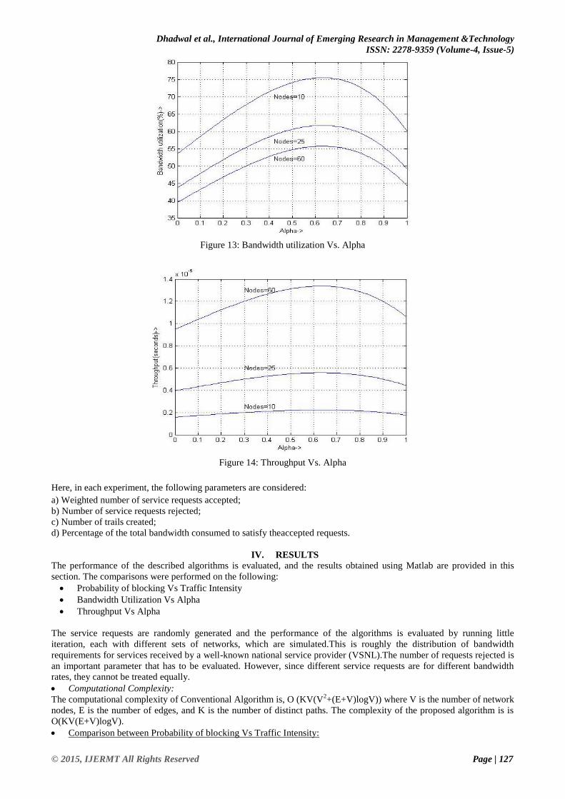
Two graphs has been plotted regarding the bandwidth utilization and throughput. The alpha factor is some value between
0 and 1, and it refers to the relative weight of a trail.
Figure 12: Magnitude vs. Frequency
Dhadwal et al., International Journal of Emerging Research in Management &Technology
ISSN: 2278-9359 (Volume-4, Issue-5)
© 2015, IJERMT All Rights Reserved Page | 127
Figure 13: Bandwidth utilization Vs. Alpha
Figure 14: Throughput Vs. Alpha
Here, in each experiment, the following parameters are considered:
a) Weighted number of service requests accepted;
b) Number of service requests rejected;
c) Number of trails created;
d) Percentage of the total bandwidth consumed to satisfy theaccepted requests.
IV. RESULTS
The performance of the described algorithms is evaluated, and the results obtained using Matlab are provided in this
section. The comparisons were performed on the following:
Probability of blocking Vs Traffic Intensity
Bandwidth Utilization Vs Alpha
Throughput Vs Alpha
The service requests are randomly generated and the performance of the algorithms is evaluated by running little
iteration, each with different sets of networks, which are simulated.This is roughly the distribution of bandwidth
requirements for services received by a well-known national service provider (VSNL).The number of requests rejected is
an important parameter that has to be evaluated. However, since different service requests are for different bandwidth
rates, they cannot be treated equally.
Computational Complexity:
The computational complexity of Conventional Algorithm is, O (KV(V2+(E+V)logV)) where V is the number of network
nodes, E is the number of edges, and K is the number of distinct paths. The complexity of the proposed algorithm is is
O(KV(E+V)logV).
Comparison between Probability of blocking Vs Traffic Intensity:

Dhadwal et al., International Journal of Emerging Research in Management &Technology
ISSN: 2278-9359 (Volume-4, Issue-5)
© 2015, IJERMT All Rights Reserved Page | 128
Figure 37: Blocking Probability vs. Traffic Intensity
In figure 15 there is a comparative study between the existing algorithms Vs. proposed algorithm. At different
nodes a blocking probability Vs Traffic intensity.
Comparison between Bandwidth Utilization Vs Alpha:
In figure 16 there is a factor which is important i.e. Bandwidth vs. Alpha. This is also improved by the proposed
algorithm shown in Section IV. Figure 16 shows comparative view of proposed vs. existing algorithm.
Figure 38: Throughput Vs. Alpha
Making comparisons between GSPP Algorithm and PSPP Algorithm performance, using some standard values, in
blocking probability, throughput and bandwidth utilization; it is clearly observed that PSPP Algorithm is better than
GSPP Algorithm in all performance criteria.
Figure 39: No. of Accepted Request Vs. Alpha
0
200
400
600
800
1000
1200
1400
1600
1800
2000
0.1 0.3 0.5 0.7 0.9
No
. of
Acc
ep
ted
Re
qu
est
s
Alpha
This Work
[7]
[8]
[9]
[10]
Dhadwal et al., International Journal of Emerging Research in Management &Technology
ISSN: 2278-9359 (Volume-4, Issue-5)
© 2015, IJERMT All Rights Reserved Page | 129
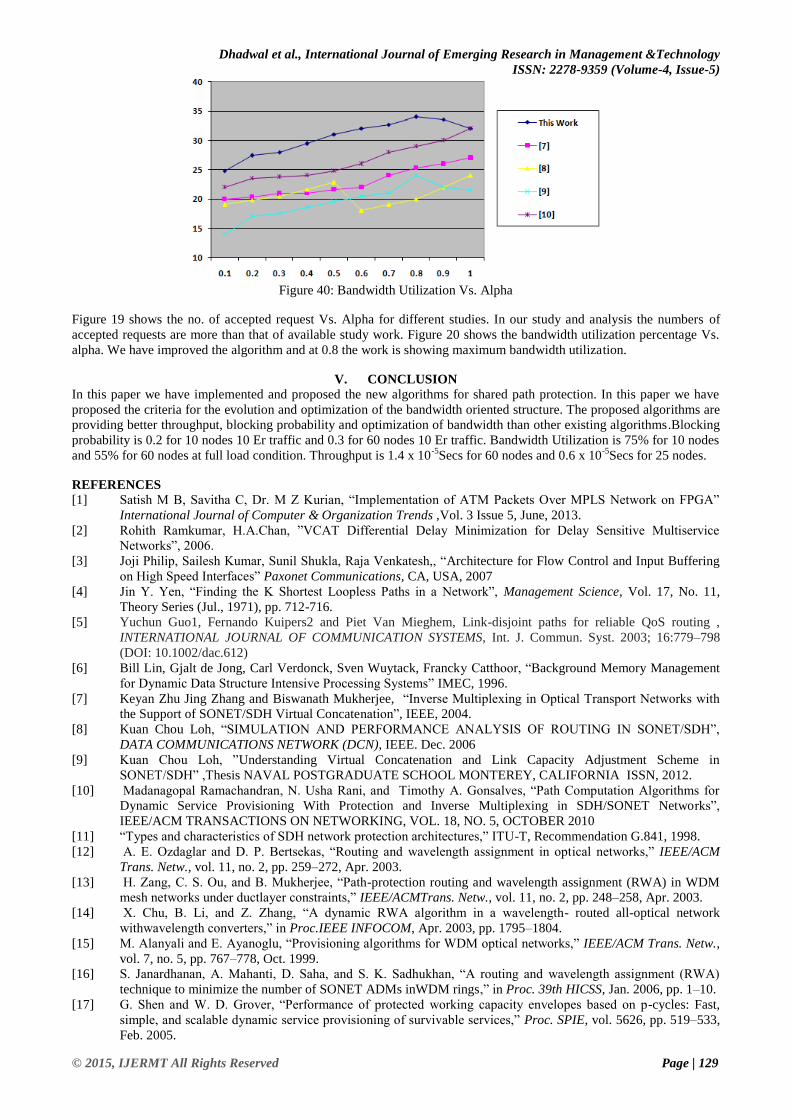
Figure 40: Bandwidth Utilization Vs. Alpha
Figure 19 shows the no. of accepted request Vs. Alpha for different studies. In our study and analysis the numbers of
accepted requests are more than that of available study work. Figure 20 shows the bandwidth utilization percentage Vs.
alpha. We have improved the algorithm and at 0.8 the work is showing maximum bandwidth utilization.
V. CONCLUSION
In this paper we have implemented and proposed the new algorithms for shared path protection. In this paper we have
proposed the criteria for the evolution and optimization of the bandwidth oriented structure. The proposed algorithms are
providing better throughput, blocking probability and optimization of bandwidth than other existing algorithms.Blocking
probability is 0.2 for 10 nodes 10 Er traffic and 0.3 for 60 nodes 10 Er traffic. Bandwidth Utilization is 75% for 10 nodes
and 55% for 60 nodes at full load condition. Throughput is 1.4 x 10⁻⁵
Secs for 60 nodes and 0.6 x 10⁻⁵
Secs for 25 nodes.
REFERENCES
[1] Satish M B, Savitha C, Dr. M Z Kurian, “Implementation of ATM Packets Over MPLS Network on FPGA”
International Journal of Computer & Organization Trends ,Vol. 3 Issue 5, June, 2013.
[2] Rohith Ramkumar, H.A.Chan, ”VCAT Differential Delay Minimization for Delay Sensitive Multiservice
Networks”, 2006.
[3] Joji Philip, Sailesh Kumar, Sunil Shukla, Raja Venkatesh,, “Architecture for Flow Control and Input Buffering
on High Speed Interfaces” Paxonet Communications, CA, USA, 2007
[4] Jin Y. Yen, “Finding the K Shortest Loopless Paths in a Network”, Management Science, Vol. 17, No. 11,
Theory Series (Jul., 1971), pp. 712-716.
[5] Yuchun Guo1, Fernando Kuipers2 and Piet Van Mieghem, Link-disjoint paths for reliable QoS routing ,
INTERNATIONAL JOURNAL OF COMMUNICATION SYSTEMS, Int. J. Commun. Syst. 2003; 16:779–798
(DOI: 10.1002/dac.612)
[6] Bill Lin, Gjalt de Jong, Carl Verdonck, Sven Wuytack, Francky Catthoor, “Background Memory Management
for Dynamic Data Structure Intensive Processing Systems” IMEC, 1996.
[7] Keyan Zhu Jing Zhang and Biswanath Mukherjee, “Inverse Multiplexing in Optical Transport Networks with
the Support of SONET/SDH Virtual Concatenation”, IEEE, 2004.
[8] Kuan Chou Loh, “SIMULATION AND PERFORMANCE ANALYSIS OF ROUTING IN SONET/SDH”,
DATA COMMUNICATIONS NETWORK (DCN), IEEE. Dec. 2006
[9] Kuan Chou Loh, ”Understanding Virtual Concatenation and Link Capacity Adjustment Scheme in
SONET/SDH” ,Thesis NAVAL POSTGRADUATE SCHOOL MONTEREY, CALIFORNIA ISSN, 2012.
[10] Madanagopal Ramachandran, N. Usha Rani, and Timothy A. Gonsalves, “Path Computation Algorithms for
Dynamic Service Provisioning With Protection and Inverse Multiplexing in SDH/SONET Networks”,
IEEE/ACM TRANSACTIONS ON NETWORKING, VOL. 18, NO. 5, OCTOBER 2010
[11] “Types and characteristics of SDH network protection architectures,” ITU-T, Recommendation G.841, 1998.
[12] A. E. Ozdaglar and D. P. Bertsekas, “Routing and wavelength assignment in optical networks,” IEEE/ACM
Trans. Netw., vol. 11, no. 2, pp. 259–272, Apr. 2003.
[13] H. Zang, C. S. Ou, and B. Mukherjee, “Path-protection routing and wavelength assignment (RWA) in WDM
mesh networks under ductlayer constraints,” IEEE/ACMTrans. Netw., vol. 11, no. 2, pp. 248–258, Apr. 2003.
[14] X. Chu, B. Li, and Z. Zhang, “A dynamic RWA algorithm in a wavelength- routed all-optical network
withwavelength converters,” in Proc.IEEE INFOCOM, Apr. 2003, pp. 1795–1804.
[15] M. Alanyali and E. Ayanoglu, “Provisioning algorithms for WDM optical networks,” IEEE/ACM Trans. Netw.,
vol. 7, no. 5, pp. 767–778, Oct. 1999.
[16] S. Janardhanan, A. Mahanti, D. Saha, and S. K. Sadhukhan, “A routing and wavelength assignment (RWA)
technique to minimize the number of SONET ADMs inWDM rings,” in Proc. 39th HICSS, Jan. 2006, pp. 1–10.
[17] G. Shen and W. D. Grover, “Performance of protected working capacity envelopes based on p-cycles: Fast,
simple, and scalable dynamic service provisioning of survivable services,” Proc. SPIE, vol. 5626, pp. 519–533,
Feb. 2005.

Dhadwal et al., International Journal of Emerging Research in Management &Technology
ISSN: 2278-9359 (Volume-4, Issue-5)
© 2015, IJERMT All Rights Reserved Page | 130
[18] M. Kodialam and T. V. Lakshman, “Dynamic routing of bandwidth guaranteed tunnels with restoration,” in
Proc. IEEE INFOCOM, Mar. 2000, pp. 902–911.
[19] J. Q. Hu, “Diverse routing in optical mesh networks,” IEEE Trans.Commun., vol. 51, no. 3, pp. 489–494, Mar.
2003.
[20] A. Todimala and B. Ramamurthy, “IMSH: An iterative heuristic for SRLG diverse routing inWDMmesh
networks,” in Proc. 13th ICCCN, Oct. 2004, pp. 199–204.
[21] A. Todimala and B. Ramamurthy, “A heuristic with bounded guaranteed to compute diverse paths under shared
protection in WDM mesh networks,” in Proc. IEEE GLOBECOM, Nov. 2005, pp. 1915–1919.
[22] Deepak Dhadwal, Ashok Arora, and V R Singh, “Enhancement and implementation of Dedicated Path
Protection for SONET/SDH Network”, International Journal of Engineering Trends and Technology (IJETT) –
Volume 14 Number 3 – Aug 2014.
[23] Deepak Dhadwal, Ashok Arora, and V R Singh,”SONET/SDH: Review of Technology and Developments”,
International Journal of Innovative Science and Modern Engineering (IJISME) ISSN: 2319-6386, Volume-2,
Issue-7, June 2014.
[24] Deepak Dhadwal, Ashok Arora ,VR Singh,” Optimization of Shared Path Protection for SONET/SDH
Network”, International Journal of Scientific & Engineering Research, Volume 5, Issue 7, July-2014
[25] R. Madanagopal, N. U. Rani, and T. A. Gonsalves, “Path computation algorithms for dynamic service
provisioning in SDH networks,” in Proc. 10th IFIP/IEEE IM, May 2007, pp. 206–215.
[26] W. Fawaz, B. Daheb, O. Audouin, B. Berde, M. Vigoureux, M. Du-Pond, and G. Pujolle, “Service level
agreement and provisioning in optical networks,” IEEE Commun. Mag., vol. 42, no. 1, pp. 36–43, Jan. 2004.
[27] W. Fawaz, B. Daheb, O. Audouin, B. Berde, M. Vigoureux, M. Du-Pond, and G. Pujolle, “Service level
agreement and provisioning in optical networks,” IEEE Commun. Mag., vol. 42, no. 1, pp. 36–43, Jan. 2004.
[28] “Network node interface for the synchronous digital hierarchy (SDH),” ITU-T, Recommendation
G.707/Y.1322, 2000.
[29] “Physical/electrical characteristics of hierarchical digital interfaces,” ITU-T, Recommendation G.703, 2001.
[30] “Types and characteristics of SDH network protection architectures,” ITU-T, Recommendation G.841, 1998.
[31] A. E. Ozdaglar and D. P. Bertsekas, “Routing and wavelength assignment in optical networks,” IEEE/ACM
Trans. Netw., vol. 11, no. 2, pp. 259–272, Apr. 2003.
[32] H. Zang, C. S. Ou, and B. Mukherjee, “Path-protection routing and wavelength assignment (RWA) in WDM
mesh networks under ductlayer constraints,” IEEE/ACMTrans. Netw., vol. 11, no. 2, pp. 248–258, Apr. 2003.
[33] X. Chu, B. Li, and Z. Zhang, “A dynamic RWA algorithm in a wavelength- routed all-optical network
withwavelength converters,” in Proc.IEEE INFOCOM, Apr. 2003, pp. 1795–1804.