
Analysis and Design of Stepped Cantilever Retaining Wall · component parts are discussed below in...
14
Analysis and Design of Stepped Cantilever Retaining Wall Dr. S.S Patil 1 1 Professor and Head, Civil Engineering Department, Walchand Insitute of Technology, Solapur, Maharashtra, India A.A.R.Bagban 2 2 Post Graduate Student, Walchand Institute of Technology, Solapur. Maharashtra, India Abstract— A retaining wall is one of the most important types of retaining structures. It is extensively used in variety of situations such as highway engineering, railway engineering, bridge engineering and irrigation engineering. Reinforced concrete retaining walls have a vertical or inclined stem cast with base slab. These are considered suitable up to a height of 6m. It resists lateral earth pressure by cantilever action of stem, toe slab and heel slab. The tendency of wall to slide forward due to lateral earth pressure should be investigated and a factor of safety of 1.5 shall be provided against sliding. Cantilever retaining walls are found best up to a height of 6m.For greater heights earth pressure due to retained fill will be higher due to lever arm effect, higher moments are produced at base, which leads to higher section for stability design as well as structural design. This proves to be an uneconomical design. As an alternative to this, one may go for counter fort retaining wall, which demands greater base area as well as steel. As a solution to this difficulty, a new approach that is to minimize effect of forces coming from retained fill , short reinforced concrete members in the form of cantilever steps are cast along the stem on the retaining face. Addition of these steps would counterbalance the locally appearing forces and will result into lesser moment and shear forces along the stem. Also it will reduce the bending action that is pressure below the base. The objectives of the study are To reduce the stresses on the retaining face of the cantilever retaining wall, it is proposed to introduce reinforced concrete steps along the stem. 2)Decide the most economical location of step along length and also along height of wall from number of trials. 3)Decide cross section of the R. C. step as per the stresses due to frictional forces in step. 4)Stability analysis of Cantilever retaining wall with steps for unit width will be done. Check for minimum and maximum stresses will be observed. 5)Cost comparison shall be carried out for these three different alternatives to give most economical retaining wall type. Index Terms— Mechanism of Concrete plates; Concrete quantity; Steel reinforcement and Cost comparison of Counter fort and Stepped Cantilever retaining wall. I. I NTRODUCTION A retaining wall is one of the most important types of soil retaining structures. The primary purpose of retaining wall is to retain earth or other material at or near vertical position. It is extensively used in variety of situations such as highway engineering, railway engineering, bridge engineering, dock and harbor engineering, irrigation engineering, land reclamation and coastal engineering etc. Reinforced concrete retaining walls have a vertical or inclined stem cast monolithic with a base slab. These are considered suitable up to a height of 6m. It resists the lateral earth pressure by cantilever action of the stem, toe slab and heel slab. Necessary reinforcements are provided to take care of the flexural stresses. The tendency of the wall to slide forward due to lateral earth pressure should be investigated and if a factor of safety is insufficient, a shear key should be designed to prevent lateral movement of the structure. A) Cantilever Retaining Walls These walls are made of reinforced cement concrete. It consists of a thin stem and a base slab cast monolithically. This type of wall is found to be economical up to a height 6 to 8m. Fig.1 B) Counter fort Retaining Walls These walls have thin vertical slabs, known as counter forts, spaced across vertical stem at regular intervals. The counter forts tie the vertical stem with the base slab. Thus the vertical stem and the base slab span between the counter forts. The purpose of providing the counter forts is to reduce the shear force and bending moments in the vertical stem and the base slab. The counter fort retaining walls are economical for a height more than 6 to 8m. Backfill Stem Surcharge Heel Toe International Journal of Engineering Research & Technology (IJERT) ISSN: 2278-0181 www.ijert.org IJERTV4IS020033 (This work is licensed under a Creative Commons Attribution 4.0 International License.) Vol. 4 Issue 02, February-2015
Transcript of Analysis and Design of Stepped Cantilever Retaining Wall · component parts are discussed below in...
Analysis and Design of Stepped Cantilever
Retaining Wall
Dr. S.S Patil
1
1Professor and Head, Civil Engineering Department,
Walchand Insitute of Technology, Solapur, Maharashtra,
India
A.A.R.Bagban2
2Post Graduate Student, Walchand Institute of
Technology, Solapur. Maharashtra, India
Abstract— A retaining wall is one of the most important types of
retaining structures. It is extensively used in variety of situations
such as highway engineering, railway engineering, bridge
engineering and irrigation engineering. Reinforced concrete
retaining walls have a vertical or inclined stem cast with base
slab. These are considered suitable up to a height of 6m. It
resists lateral earth pressure by cantilever action of stem, toe
slab and heel slab. The tendency of wall to slide forward due to
lateral earth pressure should be investigated and a factor of
safety of 1.5 shall be provided against sliding. Cantilever
retaining walls are found best up to a height of 6m.For greater
heights earth pressure due to retained fill will be higher due to
lever arm effect, higher moments are produced at base, which
leads to higher section for stability design as well as structural
design. This proves to be an uneconomical design. As an
alternative to this, one may go for counter fort retaining wall,
which demands greater base area as well as steel. As a solution
to this difficulty, a new approach that is to minimize effect of
forces coming from retained fill , short reinforced concrete
members in the form of cantilever steps are cast along the stem
on the retaining face. Addition of these steps would
counterbalance the locally appearing forces and will result into
lesser moment and shear forces along the stem. Also it will
reduce the bending action that is pressure below the base.
The objectives of the study are
To reduce the stresses on the retaining face of the
cantilever retaining wall, it is proposed to introduce
reinforced concrete steps along the stem.
2)Decide the most economical location of step along
length and also along height of wall from number of
trials.
3)Decide cross section of the R. C. step as per the
stresses due to frictional forces in step.
4)Stability analysis of Cantilever retaining wall with
steps for unit width will be done. Check for minimum
and maximum stresses will be observed.
5)Cost comparison shall be carried out for these three
different alternatives to give most economical retaining
wall type.
Index Terms— Mechanism of Concrete plates; Concrete
quantity; Steel reinforcement and Cost comparison of Counter fort
and Stepped Cantilever retaining wall.
I. INTRODUCTION
A retaining wall is one of the most important types of soil retaining structures. The primary purpose of retaining wall is to retain earth or other material at or near vertical position. It is extensively used in variety of situations such as highway engineering, railway engineering, bridge engineering, dock and harbor engineering, irrigation engineering,
land reclamation and coastal engineering etc. Reinforced concrete retaining walls have a vertical or inclined stem cast monolithic with a base slab. These are considered suitable up to a height of 6m. It resists the lateral earth pressure by cantilever action of the stem, toe slab and heel slab.
Necessary reinforcements are provided to take care of the flexural stresses. The tendency of the wall to slide forward due to lateral earth pressure should be investigated and if a factor of safety is insufficient, a shear key should be designed to prevent lateral movement of the structure.
A) Cantilever Retaining Walls
These walls are made of reinforced cement concrete. It consists of a thin stem and a base slab cast monolithically. This type of wall is found to be economical up to a height 6 to 8m.
Fig.1
B) Counter fort Retaining Walls
These walls have thin vertical slabs, known as counter forts, spaced across vertical stem at regular intervals. The counter forts tie the vertical stem with the base slab. Thus the vertical stem and the base sla b span between the counter forts. The purpose of providing the counter forts is to reduce the shear force and bending moments in the vertical stem and the base slab. The counter fort retaining walls are economical for a height more than 6 to 8m.
Backfill
Stem
Surcharge
Heel Toe
International Journal of Engineering Research & Technology (IJERT)
ISSN: 2278-0181
www.ijert.orgIJERTV4IS020033
(This work is licensed under a Creative Commons Attribution 4.0 International License.)
Vol. 4 Issue 02, February-2015
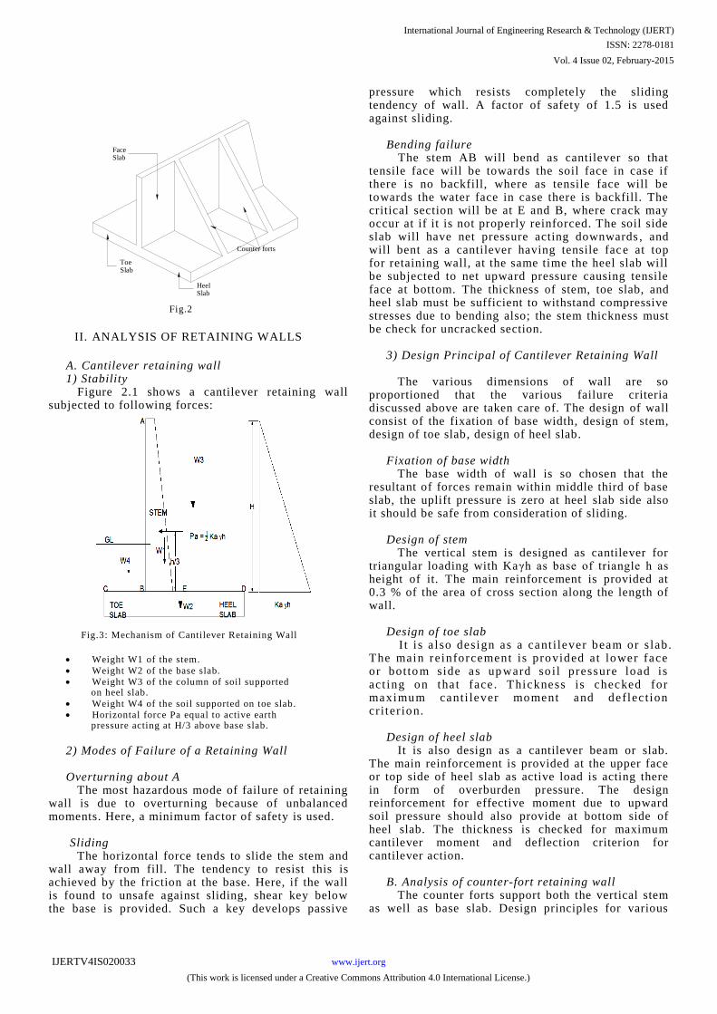
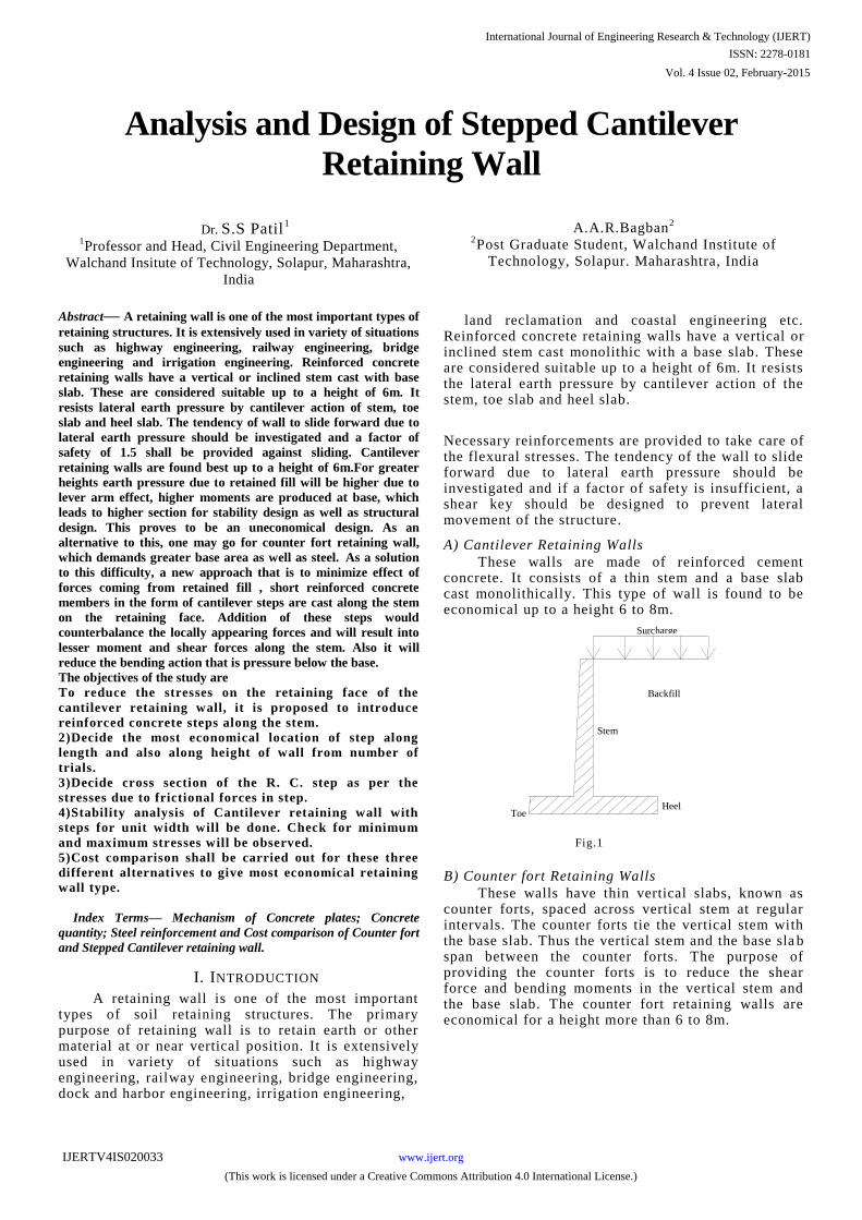
Fig.2
II. ANALYSIS OF RETAINING WALLS
A. Cantilever retaining wall 1) Stability Figure 2.1 shows a cantilever retaining wall
subjected to following forces:
Fig.3: Mechanism of Cantilever Retaining Wall
Weight W1 of the stem.
Weight W2 of the base slab.
Weight W3 of the column of soil supported on heel slab.
Weight W4 of the soil supported on toe slab.
Horizontal force Pa equal to active earth pressure acting at H/3 above base slab.
2) Modes of Failure of a Retaining Wall Overturning about A The most hazardous mode of failure of retaining
wall is due to overturning because of unbalanced moments. Here, a minimum factor of safety is used.
Sliding The horizontal force tends to slide the stem and
wall away from fill. The tendency to resist this is achieved by the friction at the base. Here, if the wall is found to unsafe against sliding, shear key below the base is provided. Such a key develops passive
pressure which resists completely the sliding tendency of wall. A factor of safety of 1.5 is used against sliding.
Bending failure The stem AB will bend as cantilever so that
tensile face will be towards the soil face in case if there is no backfill, where as tensile face will be towards the water face in case there is backfill. The critical section will be at E and B, where crack may occur at if it is not properly reinforced. The soil side slab will have net pressure acting downwards , and will bent as a cantilever having tensile fac e at top for retaining wall, at the same time the heel slab will be subjected to net upward pressure causing tensile face at bottom. The thickness of stem, toe slab, and heel slab must be sufficient to withstand compressive stresses due to bending also; the stem thickness must be check for uncracked section.
3) Design Principal of Cantilever Retaining Wall The various dimensions of wall are so
proportioned that the various failure criteria discussed above are taken care of. The design of wall consist of the fixation of base width, design of stem, design of toe slab, design of heel slab.
Fixation of base width The base width of wall is so chosen that the
resultant of forces remain within middle third of base slab, the uplift pressure is zero at heel slab side also it should be safe from consideration of sliding.
Design of stem The vertical stem is designed as cantilever for
triangular loading with Kaγh as base of triangle h as height of it. The main reinforcement is provided at 0.3 % of the area of cross section along the length of wall.
Design of toe slab I t i s a l so design as a cant i lever beam or s lab.
The main reinforcement is provided at lower face or botto m side as up ward so il pressure load is act ing on tha t face . Thickness is checked for maximum canti lever moment and deflec t ion cr i ter ion.
Design of heel slab It is also design as a cantilever beam or slab.
The main reinforcement is provided at the upper face or top side of heel slab as active load is acting there in form of overburden pressure. The design reinforcement for effective moment due to upward soil pressure should also provide at bottom side of heel slab. The thickness is checked for maximum cantilever moment and deflection criterion for cantilever action.
B. Analysis of counter-fort retaining wall The counter forts support both the vertical stem
as well as base slab. Design principles for various
Face Slab
Heel Slab
Toe Slab
Counter forts
International Journal of Engineering Research & Technology (IJERT)
ISSN: 2278-0181
www.ijert.orgIJERTV4IS020033
(This work is licensed under a Creative Commons Attribution 4.0 International License.)
Vol. 4 Issue 02, February-2015
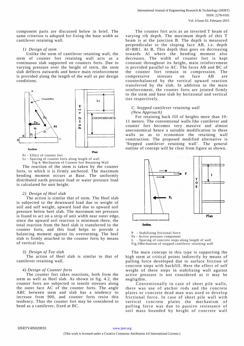
component parts are discussed below in brief. The same criterion is adopted for fixing the base width as cantilever retaining wall.
1) Design of stem Unlike the stem of cantilever retaining wall, the
stem of counter fort retaining wall acts as a continuous slab supported on counters forts. Due to varying pressure over the height of stern, the stem slab deflects outwards and hence main reinforcement is provided along the length of the wall as per design conditions.
Pc - Effect of counter fort Lc - Spacing of counter forts along length of wall
Fig.4: Mechanism of Counter fort Retaining Wall
The reaction of the stem is taken by the counter forts, to which it is firmly anchored. The maximum bending moment occurs at Base. The uniformly distributed earth pressure load or water pressure load is calculated for unit height.
2) Design of Heel slab The action is similar that of stem. The Heel slab
is subjected to the downward load due to weight of soil and self weight, upward load due to upward soil pressure below heel slab. The maximum net pressure is found to act on a strip of unit width near outer edge, since the upward soil reaction is minimum there, the total reaction from the heel slab is transferred to the counter forts, and this load helps to provide a balancing moment against its overturning. The heel slab is firmly attached to the counter forts by means of vertical ties.
3) Design of Toe slab The action of Heel slab is similar to that of
cantilever retaining wall. 4) Design of Counter forts The counter fort takes reactions, both from the
stem as well as Heel slab. As shown in fig. 4.2, the counter forts are subjected to tensile stresses along the outer face AC of the counter forts. The angle ABC between stem and slab has a tendency to increase from 900, and counter forts resist this tendency. Thus the counter fort may be considered to bend as a cantilever, fixed at BC.
The counter fort acts as an inverted T beam of varying rib depth. The maximum depth of this T beam is at the junction B. The depth is measured perpendicular to the sloping face AB, i.e. depth dl=BB1. At B, This depth thus goes on decreasing towards Al where the bending moment also decreases. The width of counter fort is kept constant throughout its height, main reinforcement is provided parallel to AC. The faces AB and BC of the counter fort remain in compression. The compressive stresses on face AB a re counterbalanced by the vertical upward reaction transferred by the slab. In addition to the main reinforcement, the counter forts are jointed firmly to the stem and base slab by horizontal and vertical ties respectively.
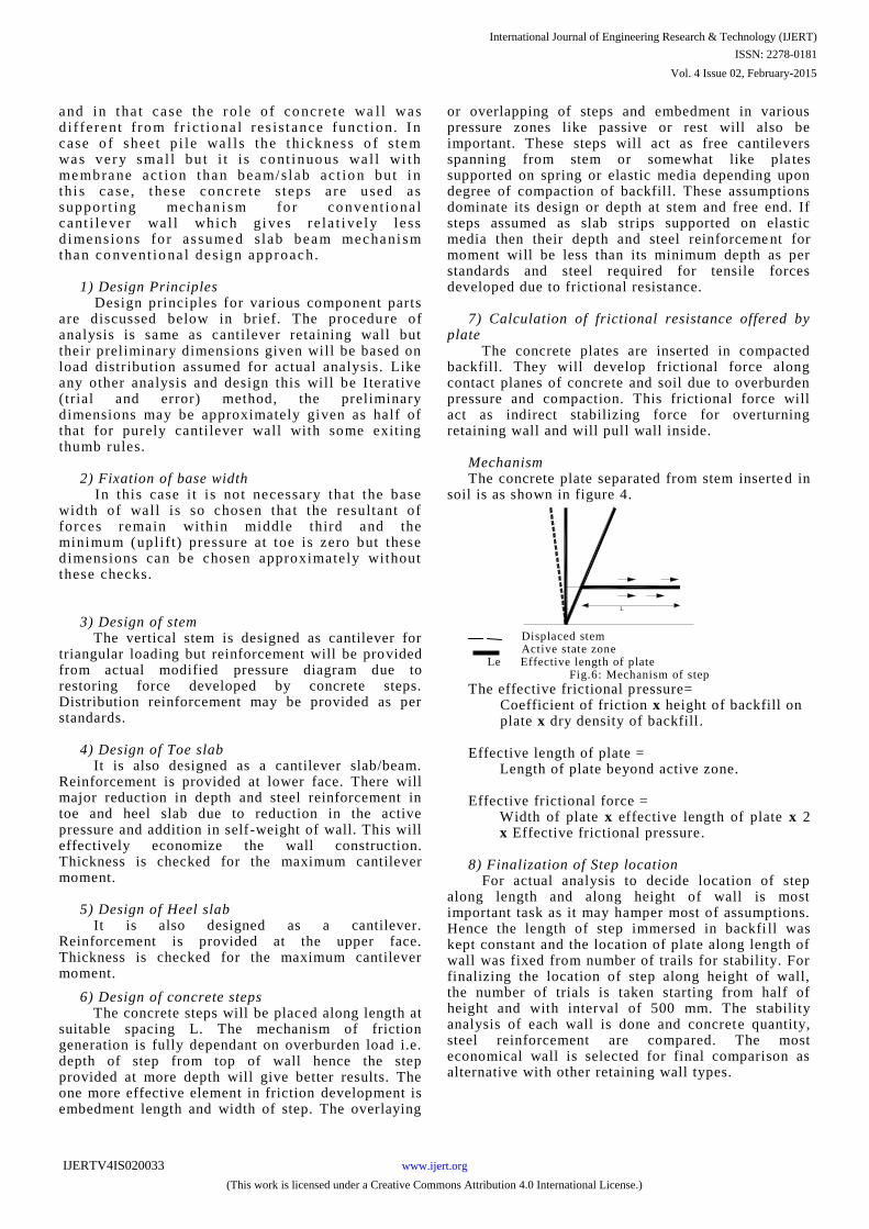
C. Stepped cantilever retaining wall (New Approach) For retaining back fill of heights more than 10-
11 meters. The conventional walls like cantilever and counter fort becomes very massive and almost uneconomical hence a suitable modification to these walls so as to economize the reta ining wall construction. The proposed modified alternative is „Stepped cantilever retaining wall‟. The general outline of concept will be clear from figure as shown.
P - Stabilizing frictional force Pa - Active pressure component L - Spacing of concrete steps along length of wall Fig.5Mechanism of stepped cantilever retaining wall
The main concept in this type is supporting the
high stem at critical points indirectly by means of pulling force developed due to surface friction of concrete steps with backfill . Here the effect of self weight of these steps in stabilizing wall against active pressure is not considered as it may be negligible.
Convent io nal ly in ca se o f shee t p i le wal l s , there was use o f anchor rods and the concre te p la tes o r co ncre t e dead man was used to develo p fr ic t io na l fo rce . I n case o f shee t p i le wal l wi th ver t ica l co ncre te p la tes the mechani sm of pul l ing force was d ue to pass ive res is tance of so i l mass bounded b y he ight o f co ncre te wal l
International Journal of Engineering Research & Technology (IJERT)
ISSN: 2278-0181
www.ijert.orgIJERTV4IS020033
(This work is licensed under a Creative Commons Attribution 4.0 International License.)
Vol. 4 Issue 02, February-2015
and in tha t ca se the ro le o f co ncre te wa l l was d i f fe rent f ro m fr ic t io na l res is t ance funct io n. I n case o f shee t p i le wa l ls the thi ckness o f s tem was very sma l l bu t i t i s co nt inuo us wa l l wi th membrane ac t ion than beam/sl ab ac t io n but in thi s ca se , t hese conc re te s tep s a re used as suppor t ing mechan i sm for co nvent io nal cant i lever wal l which gives re la t ive ly le ss d imensio ns fo r as sume d s lab beam mechani sm than co nvent io na l des ign approach.
1) Design Principles Design principles for various component parts
are discussed below in brief. The procedure of analysis is same as cantilever retaining wall but their preliminary dimensions given will be based on load distribution assumed for actual analysis. Like any other analysis and design this will be Iterative (trial and error) method, the preliminary dimensions may be approximately given as half of that for purely cantilever wall with some exiting thumb rules.
2) Fixation of base width In this case i t is not necessary that the base
width of wall is so chosen that the resultant of forces remain with in middle third and the minimum (uplift) pressure at toe is zero but these dimensions can be chosen approximately without these checks.
3) Design of stem The vertical stem is designed as cantilever for
triangular loading but reinforcement will be provided from actual modified pressure diagram due to restoring force developed by concrete steps. Distribution reinforcement may be provided as per standards.
4) Design of Toe slab It is also designed as a cantilever slab/beam.
Reinforcement is provided at lower face. There will major reduction in depth and steel reinforcement in toe and heel slab due to reduction in the active pressure and addition in self -weight of wall. This will effectively economize the wall construction. Thickness is checked for the maximum cantilever moment.
5) Design of Heel slab It is also designed as a cantilever.
Reinforcement is provided at the upper face. Thickness is checked for the maximum cantilever moment.
6) Design of concrete steps The concrete steps will be placed along length at
suitable spacing L. The mechanism of friction generation is fully dependant on overburden load i.e. depth of step from top of wall hence the step provided at more depth will give better results. The one more effective element in friction development is embedment length and width of step. The overlaying
or overlapping of steps and embedment in various pressure zones like passive or rest will also be important. These steps will act as free cantilevers spanning from stem or somewhat like pla tes supported on spring or elastic media depending upon degree of compaction of backfill. These assumptions dominate its design or depth at stem and free end. If steps assumed as slab strips supported on elastic media then their depth and steel reinforceme nt for moment will be less than its minimum depth as per standards and steel required for tensile forces developed due to frictional resistance.
7) Calculation of frictional resistance offered by
plate The concrete plates are inserted in compacted
backfill. They will develop frictional force along contact planes of concrete and soil due to overburden pressure and compaction. This frictional force will act as indirect stabilizing force for overturning retaining wall and will pull wall inside.
Mechanism The concrete plate separated from stem inserted in
soil is as shown in figure 4. Displaced stem Active state zone Le Effective length of plate
Fig.6: Mechanism of step
The effective frictional pressure= Coefficient of friction x height of backfill on plate x dry density of backfill . Effective length of plate =
Length of plate beyond active zone. Effective frictional force =
Width of plate x effective length of plate x 2 x Effective frictional pressure.
8) Finalization of Step location For actual analysis to decide location of step
along length and along height of wall is most important task as it may hamper most of assumptions. Hence the length of step immersed in backfi ll was kept constant and the location of plate along length of wall was fixed from number of trails for stability. For finalizing the location of step along height of wall, the number of trials is taken starting from half of height and with interval of 500 mm. The stability analysis of each wall is done and concrete quantity, steel reinforcement are compared. The most economical wall is selected for final comparison as alternative with other retaining wall types.
L
e
International Journal of Engineering Research & Technology (IJERT)
ISSN: 2278-0181
www.ijert.orgIJERTV4IS020033
(This work is licensed under a Creative Commons Attribution 4.0 International License.)
Vol. 4 Issue 02, February-2015

The following table shows all aspects of stepped cantilever wall for various step heights from top of wall. The comparison is also shown graphically by subsequent graphs for each height.
1. Stepped retaining wall of height 6m Assumptions 1.Back fill is enough compacted. 2.Step length embedded in backfill - 3.5m 3.Step dimensions - 400 x 300 mm Table 1: Stability analysis and cost comparison
Step
from
top
m.
Width
of toe
slab
Width
of heel
slab
Depth
of
base
slab
Total
base
slab Stem
Thik
Top Bottom
3
0.85
2.5
0.4
3.7
0.2
0.35
3.5
0.65
2.5
0.4
3.5
0.2
0.35
4
0.65
1.9
0.4
2.9
0.2
0.35
4.5
0.65
2.42
0.4
3.42
0.2
0.35
5
0.65
2.6
0.4
3.6
0.2
0.35
5.5
0.65
2.9
0.45
3.9
0.2
0.35
Upward soil
pressure in
KN/m2
Effective
frictional
force
Concrete
m3
Steel
quantity
Kg/m
Pmax.
Pmin.
101.7
295.2
38.21
2.305
138.26
103.6
292
51.85
2.3625
143.3
88
296.5
67.56
2.26
141.38
94.7
299.1
85.36
2.6055
158.99
101.7
296.1
105.23
2.815
176.65
106.9
305.4
127.18
3.2675
202.55
Graph 1: Step location Vs concrete m3
for wall Ht. 6.0 m
Graph 2: Step location Vs steel kg for wall Ht. 6.0 m
2. Stepped retaining wall of height 8m
Assumptions 1.Back fill is enough compacted. 2.Step length embedded in backfill - 4.5m 3.Step dimensions - 500 x 300 mm
Table 2: Stability analysis and cost comparison for wall ht.8m
Step
from
top
Width
of toe
slab
Width
of heel
slab
Depth
of base
slab
Total
base
slab
Stem thickness in
m
at top Bottom
4 1.3 3.95 0.47 5.65 0.25 0.4
4.5 1.2 3.9 0.5 5.5 0.25 0.4
5 1.1 3.85 0.5 5.35 0.25 0.4
5.5 0.95 3.9 0.45 5.25 0.25 0.4
6 1.15 3.4 0.45 5 0.25 0.45
6.5 1.25 3.2 0.45 4.9 0.25 0.45
7 1.35 3.12 0.45 4.995 0.25 0.525
7.5 1.45 3.15 0.45 5.2 0.25 0.6
Upward soil pressure
KN/m2
Effective
frictional
force KN
Concrete
m3
Steel
quantity
Kg/m
Pmax. Pmin.
220.63 281.53 78.91 3.9555 294.49
213.15 299.95 100.46 4.2125 272.96
217.81 295.3 124.61 4.3 280.63
206.31 294.54 151.35 4.15 275.03
197.56 295.12 180.68 4.35 320.84
183.01 295.3 212.62 4.48 313.44
177.32 289.68 247.15 4.96025 295.81
172.75 286.56 284.28 5.5275 308.79
International Journal of Engineering Research & Technology (IJERT)
ISSN: 2278-0181
www.ijert.orgIJERTV4IS020033
(This work is licensed under a Creative Commons Attribution 4.0 International License.)
Vol. 4 Issue 02, February-2015
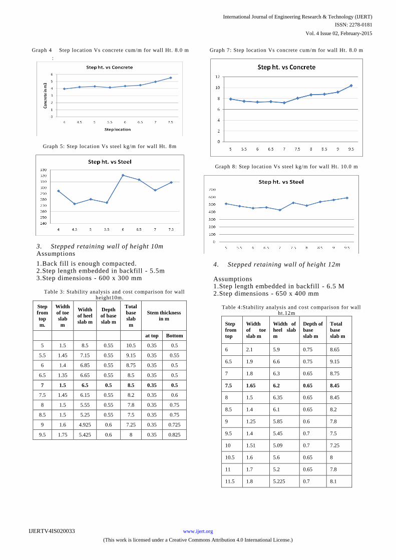
Graph 4
:
Step location Vs concrete cum/m for wall Ht. 8.0 m
Graph 5: Step location
Vs steel kg/m for wall Ht. 8m
3.
Stepped retaining wall of height 10m
Assumptions
1.Back fill is enough
compacted.
2.Step length embedded in backfill -
5.5m
3.Step dimensions -
600 x 300 mm
Table
3: Stability analysis
and cost comparison for wall height10m.
Step
from
top
m.
Width
of toe
slab
m
Width
of heel
slab m
Depth
of base
slab m
Total
base
slab
m
Stem thickness
in m
at top
Bottom
5
1.5
8.5
0.55
10.5
0.35
0.5
5.5
1.45
7.15
0.55
9.15
0.35
0.55
6
1.4
6.85
0.55
8.75
0.35
0.5
6.5
1.35
6.65
0.55
8.5
0.35
0.5
7
1.5
6.5
0.5
8.5
0.35
0.5
7.5
1.45
6.15
0.55
8.2
0.35
0.6
8
1.5
5.55
0.55
7.8
0.35
0.75
8.5
1.5
5.25
0.55
7.5
0.35
0.75
9
1.6
4.925
0.6
7.25
0.35
0.725
9.5
1.75
5.425
0.6
8
0.35
0.825
Graph 7: Step location Vs concrete cum/m for wall Ht. 8.0 m
Graph 8: Step location Vs steel kg/m for wall Ht. 10.0 m
4.
Stepped retaining wall of height 12m
Assumptions
1.Step length embedded in backfill -
6.5 M
2.Step dimensions -
650 x 400 mm
Table
4:Stability analysis and cost comparison
for wall ht.12m
Step
from
top
Width
of toe
slab m
Width of
heel slab
m
Depth of
base
slab m
Total
base
slab m
6
2.1
5.9
0.75
8.65
6.5
1.9
6.6
0.75
9.15
7
1.8
6.3
0.65
8.75
7.5
1.65
6.2
0.65
8.45
8
1.5
6.35
0.65
8.45
8.5
1.4
6.1
0.65
8.2
9
1.25
5.85
0.6
7.8
9.5
1.4
5.45
0.7
7.5
10
1.51
5.09
0.7
7.25
10.5
1.6
5.6
0.65
8
11
1.7
5.2
0.65
7.8
11.5
1.8
5.225
0.7
8.1
International Journal of Engineering Research & Technology (IJERT)
ISSN: 2278-0181
www.ijert.orgIJERTV4IS020033
(This work is licensed under a Creative Commons Attribution 4.0 International License.)
Vol. 4 Issue 02, February-2015
Upword
soil
pressure
KN/m2
Effective
frictional
force KN
Concrete
m3
Steel
quantity
Kg/m
Pmax. Pmin.
297.29 217.93 213.27 9.4875 780.71
295.99 229.29 252.98 10.1125 653.98
297.01 224.59 296.07 9.1875 664.01
299.91 240.15 342.53 9.055 602.19
295.05 249.66 392.37 9.2925 665.24
286.61 260.06 445.59 9.7925 704.89
270.77 280.76 502.18 9.405 855.36
255.28 289.2 562.14 10 856.7
240.75 294.08 562.14 10.075 861.16
245.75 283.49 692.2 11.2375 810.15
244.36 283.43 762.29 11.945 822.89
249.26 283.24 835.76 11.85125 877.55
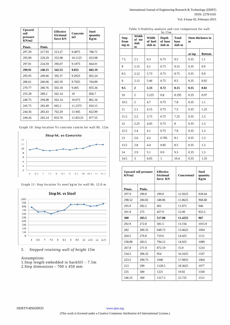
Graph 10: Step location Vs concrete cum/m for wall Ht. 12m
Graph 11: Step location Vs steel kg/m for wall Ht. 12.0 m
5. Stepped retaining wall of height 15m Assumptions 1.Step length embedded in backfil l – 7.5m 2.Step dimensions - 700 x 450 mm
Table 5:Stability analysis and cost comparison for wall ht.15m
Step
from
top m
Width
of toe
slab
m
Width
of heel
slab m
Depth
of base
slab m
Total
base
slab m
Stem thickness in
m
at top Bottom
7.5 2.1 6.3 0.75 9.5 0.35 1.1
8 2.15 6.1 0.75 9.15 0.35 0.9
8.5 2.12 5.73 0.75 8.75 0.35 0.9
9 2.12 5.46 0.75 8.5 0.35 0.92
9.5 2 5.33 0.72 8.15 0.35 0.82
10 2 5.225 0.8 8.195 0.35 0.97
10.5 2 4.7 0.75 7.8 0.35 1.1
11 2.1 4.15 0.75 7.5 0.35 1.25
11.5 2.2 3.75 0.75 7.25 0.35 1.3
12 2.25 4.45 0.75 8 0.35 1.3
12.5 2.4 4.1 0.75 7.8 0.35 1.3
13 2.6 4.2 0.785 8.1 0.35 1.3
13.5 2.8 4.4 0.85 8.5 0.35 1.3
14 2.9 5.1 0.9 9.3 0.35 1.3
14.5 3 6.05 1 10.4 0.35 1.35
Upward soil pressure
KN/m2
Effective
frictional
force KN
Concretem3
Steel
quantity
Kg/m
Pmax.
Pmin.
297.9
290.8
299.8
12.5625
928.64
298.52
284.82
348.86
11.8625
968.68
295.9
282.2
401
11.875
946
291.9
275
457.9
12.09
925.5
300
283.5
517.88
11.4255
967
292.9
272.8
581.5
13.156
1015.9
282
280.35
648.73
13.4625
1004
264.5
276.8
719.6
14.425
1111
238.88
283.5
794.12
14.925
1089
267.8
271.9
872.19
15.9
1233
234.5
286.35
954
16.1625
1167
223.5
290.75
1040
17.0835
1064
213
299
1128.5
18.3625
1077
225
300
1221
19.92
1350
246.25
300
1317.5
22.725
1511
International Journal of Engineering Research & Technology (IJERT)
ISSN: 2278-0181
www.ijert.orgIJERTV4IS020033
(This work is licensed under a Creative Commons Attribution 4.0 International License.)
Vol. 4 Issue 02, February-2015
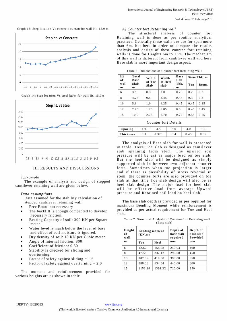
Graph 13: Step location Vs concrete cum/m for wall Ht. 15.0 m
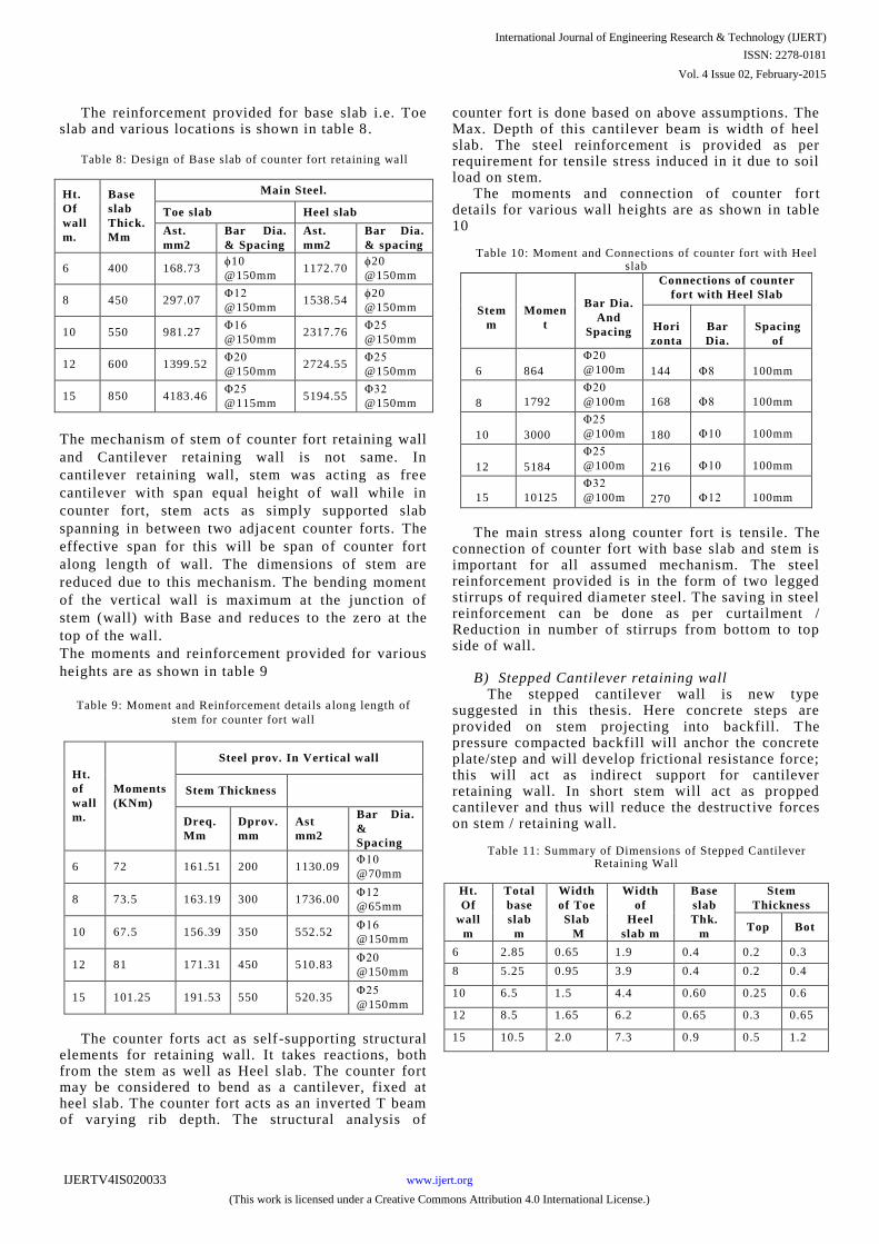
Graph 14: Step location Vs steel kg/m for wall Ht. 15.0m
III. RESULTS AND DISSCUSSIONS
1.Example The example of analysis and design of stepped
cantilever retaining wall are given below. Data assumptions Data assumed for the stability calculation of stepped cantilever retaining wall:
Free Board not necessary
The backfill is enough compacted to develop necessary friction.
Bearing Capacity of soil: 300 KN per Square meter
Water level is much below the level of base and effect of soil moisture is ignored.
Dry density of soil: 18 KN per Cubic meter
Angle of internal friction: 300
Coefficient of friction: 0.60
Stability is checked for sliding and overturning.
Factor of safety against sliding = 1.5
Factor of safety against overturning = 2.0 The moment and reinforcement provided for
various heights are as shown in table
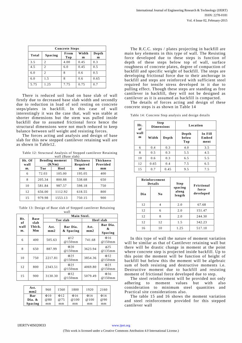
A) Counter fort Retaining wall The structural analysis of counter fort
Retaining wall is done as per routine analytical practices. Generally these walls are use for span more than 6m, but here in order to compare the results analysis and design of these counter fort retaining walls is done for Heights 6m to 15m. The mechanism of this wall is different from cantilever wall and here Base slab is more important design aspect.
Table 6: Dimensions of Counter fort Retaining Wall
Ht
of
wall
m
Total
Base
Slab
m
Width
of Toe
Slab
Width
of Heel
slab
Base
slab
Thk.
m
Stem Thk. m
Top
Botm.
6
3.5
0.3
3.0
0.28
0.2
0.2
8
4.25
0.5
3.45
0.35
0.3
0.3
10
5.6
1.0
4.25
0.45
0.45
0.35
12
7.75
1.25
6.05
0.5
0.45
0.45
15
10.0
2.75
6.70
0.77
0.55
0.55
Counter fort Details
Spacing 4.0 3.5 3.0 3.0 3.0
Thickness 0.3 0.375 0.4 0.45 0.55
The analys is o f Base s lab fo r wal l is presented in tab le Here Toe slab is designed as cant i lever slab spanning from stem. The upward so il pressure wi l l be act as major load on toe s lab. But the heel slab wi l l be des igned as simply supported slab in be tween two adjacent counter for ts . Sometimes when toe projec tion i s larger and i f there i s possib i l i ty o f stress reversa l in stem, the counter for ts are also provided on toe slab at tha t t ime Toe s lab des ign wi l l a l so be as heel s lab des ign .The major load for hee l slab wi l l be e ffect ive load from average Up ward pressure and Reta ined soil load on heel s lab.
The base slab depth is provided as per required for
maximum Bending Moment while reinforcement is provided as per actual requirement for Toe and Heel slab.
Table 7: Structural Analysis of Counter -fort Retaining wall
(Base slab)
Height
of wall m
Bending moment (KN.m)
Depth of base slab required
mm
Depth of base slab Provided
mm Toe Heel
6 12.67 158.98 240.03 400
8 47.58 232.12 290.00 450
10 187.55 419.80 390.00 550
12 288.36 534.34 440.00 600
15 1152.18 1391.32 710.00 850
International Journal of Engineering Research & Technology (IJERT)
ISSN: 2278-0181
www.ijert.orgIJERTV4IS020033
(This work is licensed under a Creative Commons Attribution 4.0 International License.)
Vol. 4 Issue 02, February-2015
The reinforcement provided for base slab i.e. Toe slab and various locations is shown in table 8 .
Table 8: Design of Base slab of counter fort retaining wall
Ht.
Of
wall
m.
Base
slab
Thick.
Mm
Main Steel.
Toe slab Heel slab
Ast.
mm2
Bar Dia.
& Spacing
Ast.
mm2
Bar Dia.
& spacing
6 400 168.73 ϕ10
@150mm 1172.70
ϕ20
@150mm
8 450 297.07 Φ12
@150mm 1538.54
ϕ20
@150mm
10 550 981.27 Φ16
@150mm 2317.76
Φ25
@150mm
12 600 1399.52 Φ20
@150mm 2724.55
Φ25
@150mm
15 850 4183.46 Φ25
@115mm 5194.55
Φ32
@150mm
The mechanism of stem of counter fort retaining wall
and Cantilever retaining wall is not same. In
cantilever retaining wall, stem was acting as free
cantilever with span equal height of wall while in
counter fort, stem acts as simply supported slab
spanning in between two adjacent counter forts. The
effective span for this will be span of counter fort
along length of wall. The dimensions of stem are
reduced due to this mechanism. The bending moment
of the vertical wall is maximum at the junction of
stem (wall) with Base and reduces to the zero at the
top of the wall.
The moments and reinforcement provided for various
heights are as shown in table 9
Table 9: Moment and Reinforcement details a long length of
stem for counter fort wall
Ht.
of
wall
m.
Moments
(KNm)
Steel prov. In Vertical wall
Stem Thickness
Dreq.
Mm
Dprov.
mm
Ast
mm2
Bar Dia.
&
Spacing
6 72 161.51 200 1130.09 Φ10
@70mm
8 73.5 163.19 300 1736.00 Φ12
@65mm
10 67.5 156.39 350 552.52 Φ16
@150mm
12 81 171.31 450 510.83 Φ20
@150mm
15 101.25 191.53 550 520.35 Φ25
@150mm
The counter forts act as self-supporting structural
elements for retaining wall. It takes reactions, both from the stem as well as Heel slab. The counter fort may be considered to bend as a cantilever, fixed at heel slab. The counter fort acts as an inverted T beam of varying rib depth. The structural analysis of
counter fort is done based on above assumptions. The Max. Depth of this cantilever beam is width of heel slab. The steel reinforcement is provided as per requirement for tensile stress induced in it due to soil load on stem.
The moments and connection of counter for t details for various wall heights are as shown in table 10
Table 10: Moment and Connections of counter fort with Heel
slab
Stem
m
Momen
t
Bar Dia.
And
Spacing
Connections of counter
fort with Heel Slab
Hori
zonta
l
Forc
e
Bar
Dia.
Spacing
of
Stirrups
6
864
Φ20
@100m
m
144
Φ8
100mm
8
1792
Φ20
@100m
m
168
Φ8
100mm
10
3000
Φ25
@100m
m
180
Φ10
100mm
12
5184
Φ25
@100m
m
216
Φ10
100mm
15
10125
Φ32
@100m
m
270
Φ12
100mm
The main stress along counter fort is tensile. The
connection of counter fort with base slab and stem is important for all assumed mechanism. The steel reinforcement provided is in the form of two legged stirrups of required diameter steel. The saving in steel reinforcement can be done as per curtailment / Reduction in number of stirrups from bottom to top side of wall.
B) Stepped Cantilever retaining wall The stepped cantilever wall is new type
suggested in this thesis. Here concrete steps are provided on stem projecting into backfill. The pressure compacted backfill will anchor the concrete plate/step and will develop frictional resistance force; this will act as indirect support for cantilever retaining wall. In short stem will act as propped cantilever and thus will reduce the destruct ive forces on stem / retaining wall.
Table 11: Summary of Dimensions of Stepped Cantilever
Retaining Wall
Ht.
Of
wall
m
Total
base
slab
m
Width
of Toe
Slab
M
Width
of
Heel
slab m
Base
slab
Thk.
m
Stem
Thickness
Top Bot
6 2.85 0.65 1.9 0.4 0.2 0.3
8 5.25 0.95 3.9 0.4 0.2 0.4
10 6.5 1.5 4.4 0.60 0.25 0.6
12 8.5 1.65 6.2 0.65 0.3 0.65
15 10.5 2.0 7.3 0.9 0.5 1.2
International Journal of Engineering Research & Technology (IJERT)
ISSN: 2278-0181
www.ijert.orgIJERTV4IS020033
(This work is licensed under a Creative Commons Attribution 4.0 International License.)
Vol. 4 Issue 02, February-2015
Concrete Steps
Total Spacing From
Top
Width
m
Depth
m
3.5 2 4.00 0.45 0.3
4.5 2 6.0 0.45 0.5
6.0 2 8 0.6 0.5
6.0 1.5 8 0.6 0.65
5.75 1.25 7.75 0.75 0.7
There is reduced soil load on base slab of wall firstly due to decreased base slab width and secondly due to reduction in load of soil resting on concrete steps/plates in backfill. In this case of wall interestingly it was the case that, wall was stable at shorter dimensions but the stem was pulled inside backfill due to assumed frictional force hence the structural dimensions were not much reduced to keep balance between self weight and resisting forces.
The forces acting and analysis and design of base slab for this new stepped cantilever retaining wall are as shown in Table12.
Table 12: Structural Analysis of Stepped cantilever Retaining
wall (Base slab)
Ht. Of
wall
m.
Bending moment
(KNm)
Thickness
Required
mm
Thickness
Provided
mm Toe Heel
6 72.03 105.00 195.05 400
8 205.34 800.88 538.68 650
10 581.84 987.57 598.18 750
12 656.00 1112.92 618.55 800
15 979.98 1553.13 750.15 900
Table 13: Design of Base slab of Stepped cantilever Retaining
wall
Ht.
of
wall
m.
Base
slab
Thick.
Mm
Main Steel.
Toe slab Heel slab
Ast.
mm2
Bar Dia.
& Spacing
Ast.
mm2
Bar Dia.
&
Spacing
6 400 505.63 ϕ12
@150mm 741.68
Φ16
@150mm
8 650 887.99 Φ20
@150mm 3623.94
ϕ25
@135mm
10 750 2217.81 Φ25
@150mm 3854.36
Φ32
@150mm
12 800 2343.51 Φ25
@150mm 4069.80
Φ25
@150mm
15 900 3130.30 Φ32
@150mm 5079.49
Φ36
@150mm
Ast.
mm2 960 1560 1800 1920 2160
Bar
Dia. &
Spacing
Φ10
@80
mm
Φ12
@75
mm
Φ16
@100
mm
Φ16
@100
mm
Φ16
@90
mm
The R.C.C. steps / plates projecting in backfill are
main key elements in this type of wall. The Resisting force developed due to these steps is function of depth of these steps below top of wall, surface roughness of concrete plates, degree of compaction of backfill and specific weight of backfill. The steps are developing frictional force due to their anchorage in backfill and steps are reinforced with sufficient steel required for tensile stress developed in it due to pulling effect. Though these steps are standing as free cantilever in backfill, they will not be designed as cantilever as it is assumed as backfill is compacted.
The details of forces acting and design of these concrete steps is as shown in Table 14
Table 14: Concrete Step analysis and design d etails
Ht.
of
wall
m
Step
Dimensions
Location
Width Depth
Depth
below
Top
In Fill
Embed
ment
6 0.4 0.3 4.0 3.5
8 0.5 0.3 5.5 4.5
10 0.6 0.3 6.5 5.5
12 0.65 0.4 7.5 6.5
15 0.7 0.45 9.5 7.5
Reinforcement
Details Step
spacing
along
length
Frictional
force
developed Dia No
12 4 2.0 67.68
12 6 2.0 151.47
12 8 2.0 244.30
12 12 1.5 342.23
16 10 1.25 517.10
In this type of wall the nature of moment variation will be similar as that of Cantilever retaining wall but there will be drastic change in moment at the point where concrete step is projected inside backfill. Up to this point the moment will be function of height of backfill but below this the moment will be algebraic sum of both resisting and destructive moments i.e. Destructive moment due to backfill and resisting moment of frictional force developed due to step.
The steel reinforcement will be provided not only adhering to moment values but with also consideration to minimum steel quantities and Practical site considerations also.
The table 15 and 16 shows the moment variation and steel reinforcement provided for this stepped cantilever wall
International Journal of Engineering Research & Technology (IJERT)
ISSN: 2278-0181
www.ijert.orgIJERTV4IS020033
(This work is licensed under a Creative Commons Attribution 4.0 International License.)
Vol. 4 Issue 02, February-2015
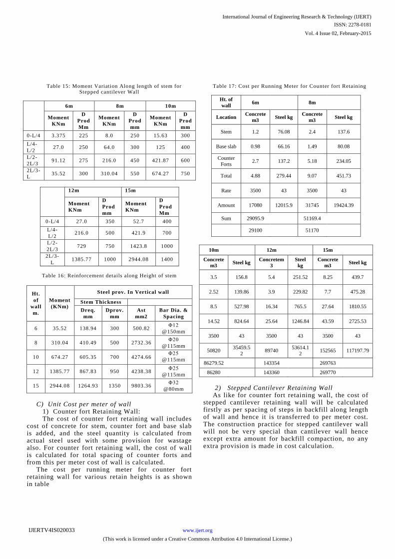
Table 15: Moment Variation Along length of stem for Stepped cantilever Wall
6m 8m 10m
Moment
KNm
D
Prod
Mm
Moment
KNm
D
Prod
mm
Moment
KNm
D
Prod
mm
0-L/4 3.375 225 8.0 250 15.63 300
L/4-
L/2 27.0 250 64.0 300 125 400
L/2-
2L/3 91.12 275 216.0 450 421.87 600
2L/3-
L 35.52 300 310.04 550 674.27 750
Table 16: Reinforcement details along Height of stem
Ht.
of
wall
m.
Moment
(KNm)
Steel prov. In Vertical wall
Stem Thickness
Dreq.
mm
Dprov.
mm
Ast
mm2
Bar Dia. &
Spacing
6 35.52 138.94 300 500.82 Φ12
@150mm
8 310.04 410.49 500 2732.36 Φ20
@115mm
10 674.27 605.35 700 4274.66 Φ25
@115mm
12 1385.77 867.83 950 4238.38
Φ25
@115mm
15 2944.08 1264.93 1350 9803.36 Φ32
@80mm
C) Unit Cost per meter of wall 1) Counter fort Retaining Wall: The cost of counter fort retaining wall includes
cost of concrete for stem, counter fort and base slab is added, and the steel quantity is calculated from actual steel used with some provision for wastage also. For counter fort retaining wall, the cost of wall is calculated for total spacing of counter forts and from this per meter cost of wall is calculated.
The cost per running meter for counter fort retaining wall for various retain heights is as shown in table
Table 17: Cost per Running Meter for Counter fort Retaining
Ht. of
wall 6m 8m
Location Concrete
m3 Steel kg
Concrete
m3 Steel kg
Stem 1.2 76.08 2.4 137.6
Base slab 0.98 66.16 1.49 80.08
Counter
Forts 2.7 137.2 5.18 234.05
Total 4.88 279.44 9.07 451.73
Rate 3500 43 3500 43
Amount 17080 12015.9 31745 19424.39
Sum 29095.9 51169.4
29100 51170
10m 12m 15m
Concrete
m3 Steel kg
Concretem
3
Steel
kg
Concrete
m3 Steel kg
3.5 156.8 5.4 251.52 8.25 439.7
2.52 139.86 3.9 229.82 7.7 475.28
8.5 527.98 16.34 765.5 27.64 1810.55
14.52 824.64 25.64 1246.84 43.59 2725.53
3500 43 3500 43 3500 43
50820 35459.5
2 89740
53614.12
152565 117197.79
86279.52 143354 269763
86280 143360 269770
2) Stepped Cantilever Retaining Wall As like for counter fort retaining wall, the cost of
stepped cantilever retaining wall will be calculated firstly as per spacing of steps in backfill along length of wall and hence it is transferred to per meter cost. The construction practice for stepped cantilever wall will not be very special than cantilever wall hence except extra amount for backfill compaction, no any extra provision is made in cost calculation.
12m 15m
Moment
KNm
D
Prod
mm
Moment
KNm
D
Prod
Mm
0-L/4 27.0 350 52.7 400
L/4-
L/2 216.0 500 421.9 700
L/2-
2L/3 729 750 1423.8 1000
2L/3-
L 1385.77 1000 2944.08 1400
International Journal of Engineering Research & Technology (IJERT)
ISSN: 2278-0181
www.ijert.orgIJERTV4IS020033
(This work is licensed under a Creative Commons Attribution 4.0 International License.)
Vol. 4 Issue 02, February-2015
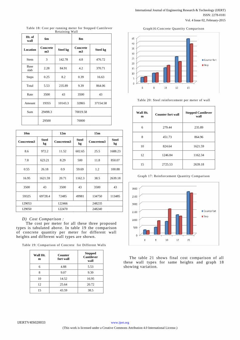
Table 18: Cost per running meter for Stepped Cantilever Retaining Wall
Ht. of
wall
6m
8m
Location
Concrete
m3
Steel kg
Concrete
m3
Steel kg
Stem
3
142.78
4.8
476.72
Base slab
2.28
84.91
4.2
370.71
Steps
0.25
8.2
0.39
16.63
Total
5.53
235.89
9.39
864.06
Rate
3500
43
3500
43
Amount
19355
10143.3
32865
37154.58
Sum
29498.3
70019.58
29500
70000
10m
12m
15m
Concretem3
Steel
kg
Concretem3
Steel
kg
Concretem3
Steel
kg
8.6
972.2
11.52
602.65
25.5
1688.23
7.8
623.21
8.29
500
11.8
850.07
0.55
26.18
0.9
59.69
1.2
100.88
16.95
1621.59
20.71
1162.3
38.5
2639.18
3500
43
3500
43
3500
43
59325
69728.4
72485
49981
134750
113485
129053
122466
248235
129050
122470
248240
D) Cost Comparison :
The cost per meter for all these three proposed types
is tabulated above. In table 19 the comparison of concrete quantity per meter for different wall
heights and different wall types are shown.
Table
19: Comparison of Concrete
for Different Walls
Wall Ht.
m
Counter
fort wall
Stepped
Cantilever
wall
6
4.88
5.53
8
9.07
9.39
10
14.52
16.95
12
25.64
20.72
15
43.59
38.5
Graph16:Concrete Quantity Comparison
Table 20: Steel reinforcement per meter of wall
Wall Ht.
m
Counter fort wall
Stepped Cantilever
wall
6
279.44
235.89
8
451.73
864.96
10
824.64
1621.59
12
1246.84
1162.34
15
2725.53
2639.18
Graph 17: Reinforcement Quantity Comparison
The table 21
shows final cost comparison of all these wall types for same heights and graph 18
showing variation.
International Journal of Engineering Research & Technology (IJERT)
ISSN: 2278-0181
www.ijert.orgIJERTV4IS020033
(This work is licensed under a Creative Commons Attribution 4.0 International License.)
Vol. 4 Issue 02, February-2015
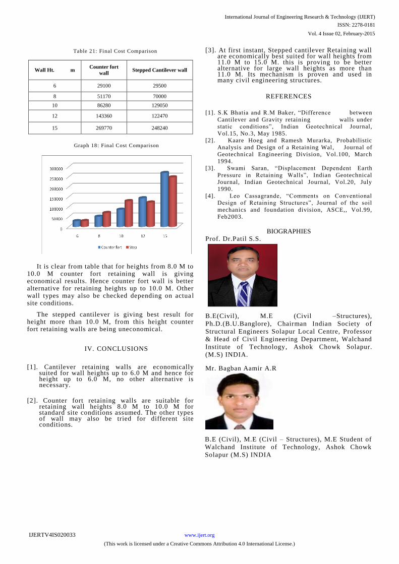
Table 21: Final Cost Comparison
Wall Ht. m
Counter fort
wall
Stepped Cantilever wall
6
29100
29500
8
51170
70000
10
86280
129050
12
143360
122470
15
269770
248240
Graph 18: Final Cost Comparison
It is clear from table that for heights from 8.0 M to 10.0 M counter fort retaining wall is giving economical results. Hence counter fort wall is better alternative for retaining heights up to 10.0 M. Other wall types may also be checked depending on actua l site conditions.
The stepped cantilever is giving best result for height more than 10.0 M, from this height counter fort retaining walls are being uneconomical.
IV.
CONCLUSIONS
[1]. Cantilever retaining walls are economically
suited for wall heights up to 6.0 M and hence for height up to 6.0 M, no other alternative is necessary.
[2]. Counter fort retaining walls are suitable for
retaining wall heights 8.0 M to 10.0 M for standard site conditions assumed. The other types of wall
may also be tried for different site conditions.
[3]. At first instant, Stepped cantilever Retaining wall are economically best suited for wall heights from 11.0 M to 15.0 M. this is proving to be better alternative for large wall heights as more than 11.0 M. Its mechanism is proven and used in many civil engineering structures.
REFERENCES
[1]. S.K Bhatia and R.M Baker, “Difference
between
Cantilever and Gravity retaining walls
under
static conditions”, Indian Geotechnical Journal,
Vol.15, No.3, May 1985.
[2]. Kaare Hoeg and Ramesh Murarka, Probabilistic
Analysis
and Design of a Retaining Wal, Journal of
Geotechnical Engineering Division, Vol.100, March
1994.
[3].
Swami Saran, “Displacement Dependent
Earth
Pressure in Retaining Walls”,
Indian Geotechnical
Journal, Indian Geotechnical Journal, Vol.20, July
1990.
[4]. Leo Cassagrande, “Comments on Conventional
Design of Retaining Structures”, Journal of the soil
mechanics and foundation division, ASCE,, Vol.99,
Feb2003.
BIOGRAPHIES
Prof. Dr.Patil S.S.
B.E(Civil), M.E (Civil –Structures),
Ph.D.(B.U.Banglore), Chairman Indian Society of
Structural Engineers Solapur Local Centre, Professor
& Head of Civil Engineering Department, Walchand
Institute of Technology, Ashok Chowk Solapur.
(M.S) INDIA.
Mr. Bagban Aamir A.R
B.E (Civil), M.E (Civil – Structures), M.E Student of
Walchand Institute of Technology, Ashok Chowk
Solapur (M.S) INDIA
International Journal of Engineering Research & Technology (IJERT)
ISSN: 2278-0181
www.ijert.orgIJERTV4IS020033
(This work is licensed under a Creative Commons Attribution 4.0 International License.)
Vol. 4 Issue 02, February-2015