Analysis and Design of ejector freezing system
12
Analysis and Design of ejector freezing system Alapati Venkateswarlu 1* , A. Adilakshmi 2 & V.K. Sharma 3 1 Professor, Mechanical, VR Siddhartha College of Engineering, Vijayawada, India. 2 Professor, PVP Siddhartha Institute of Technology, Vijayawada, India. 3 Professor and Vice Chancellor, Bhagawanth University, Ajmeer, India. *Corresponding author E-mail:[email protected] Abstract The heat driven ejector refrigeration framework offers the benefit of straightforwardness and can work from low-temperature heat vitality sources. There by, it turns out to be a good substitute to the conventional compressor-driven refrigeration system when any or a combination of heat sources is available. Chillers may speak to a contender for absorption chillers, when their cost per unit cooling power ends up equivalent or lower. This objective isn't a long way from our present accomplishments. If input energy is waste or renewable heat, the system operating cost is mainly due to the investment in heat exchangers .Therefore, a cost reduction requires an increase of COP. This last might be enhanced by a careful design of the ejector, which requires a profound understanding into the thermodynamics and fluid flow and their complex physics. The devices and the learning for a propelled configuration are as of now accessible and the change potential is huge. Since ejector utilizes low grade thermal energy for refrigeration, so in this way as we have high thermal energy rejection in automobiles exhaust so this thermal energy can be used as heat input to the generator. By doing this the extra power developed by engine to run compressor of A/C can be eliminated and which in turn reduces the fuel consumption. here the whole performance of system depends on the efficient design of the ejector (thermocompressor). The refrigerant gas used here is R134A,R410A for which the gamma (c p /c v ) value is 1.292 & according to this the ratio of inlet pressure(p o ) to the exit pressure(p e ) i.ep o /p e =0.562 therefore for different inlet pressure & back pressure values the primary motive nozzle is designed whether it should be convergent or convergent-divergent. In the same way the generator, condenser, refrigerant liquid pump capacities are calculated. If the suction pressure of ejector is high then the refrigerant in the evaporator evaporates at low temperature (t e ) therebywe can get more COP. Keywords: Ejector, freezing system,renewable heat, Mixing Chamber, CFD, R134A, R410A. 1. Introduction Over the past few years, the concerning on energy saving and environment protecting has become an increasingly predominant businesses and increment in populace have caused an awesome request of cooling and refrigeration application which utilize the mechanical vapor compression system frameworks. These systems are generally powered by power created by consuming fossil fuels. The fossil fuel consumption can contribute to the global warming–the “greenhouse effect”. This compels more and more researchers turn to make utilization of low grade thermal energy The ejector refrigeration framework gives a promising method for delivering a cooling impact by using waste heat from modern process and inside burning motor or utilizing sustainable power source, for example, sunlight based power and geothermal vitality. With the improvement of innovation, these frameworks can work utilizing low- temperature GORTERIA JOURNAL VOLUME 33, ISSUE 12 - 2020 ISSN: 0017-2294 Page No: 429
Transcript of Analysis and Design of ejector freezing system

Analysis and Design of ejector freezing system
Alapati Venkateswarlu1*
, A. Adilakshmi2 & V.K. Sharma
3
1Professor, Mechanical, VR Siddhartha College of Engineering, Vijayawada, India.
2Professor, PVP Siddhartha Institute of Technology, Vijayawada, India.
3Professor and Vice Chancellor, Bhagawanth University, Ajmeer, India.
*Corresponding author E-mail:[email protected]
Abstract
The heat driven ejector refrigeration framework offers the benefit of straightforwardness and can work
from low-temperature heat vitality sources. There by, it turns out to be a good substitute to the conventional
compressor-driven refrigeration system when any or a combination of heat sources is available. Chillers may
speak to a contender for absorption chillers, when their cost per unit cooling power ends up equivalent or lower.
This objective isn't a long way from our present accomplishments. If input energy is waste or renewable heat, the
system operating cost is mainly due to the investment in heat exchangers .Therefore, a cost reduction requires an
increase of COP. This last might be enhanced by a careful design of the ejector, which requires a profound
understanding into the thermodynamics and fluid flow and their complex physics. The devices and the learning
for a propelled configuration are as of now accessible and the change potential is huge. Since ejector utilizes low
grade thermal energy for refrigeration, so in this way as we have high thermal energy rejection in automobiles
exhaust so this thermal energy can be used as heat input to the generator. By doing this the extra power
developed by engine to run compressor of A/C can be eliminated and which in turn reduces the fuel consumption.
here the whole performance of system depends on the efficient design of the ejector (thermocompressor). The
refrigerant gas used here is R134A,R410A for which the gamma (cp/cv) value is 1.292 & according to this the
ratio of inlet pressure(po) to the exit pressure(pe) i.epo/pe=0.562 therefore for different inlet pressure & back
pressure values the primary motive nozzle is designed whether it should be convergent or convergent-divergent.
In the same way the generator, condenser, refrigerant liquid pump capacities are calculated. If the suction
pressure of ejector is high then the refrigerant in the evaporator evaporates at low temperature (te) therebywe can
get more COP.
Keywords: Ejector, freezing system,renewable heat, Mixing Chamber, CFD, R134A, R410A.
1. Introduction
Over the past few years, the concerning on energy saving and environment protecting has become an
increasingly predominant businesses and increment in populace have caused an awesome request of cooling and
refrigeration application which utilize the mechanical vapor compression system frameworks. These systems are
generally powered by power created by consuming fossil fuels.
The fossil fuel consumption can contribute to the global warming–the “greenhouse effect”. This compels
more and more researchers turn to make utilization of low grade thermal energy The ejector refrigeration
framework gives a promising method for delivering a cooling impact by using waste heat from modern process
and inside burning motor or utilizing sustainable power source, for example, sunlight based power and
geothermal vitality. With the improvement of innovation, these frameworks can work utilizing low- temperature
GORTERIA JOURNAL
VOLUME 33, ISSUE 12 - 2020
ISSN: 0017-2294
Page No: 429
warm Source beneath 100 °C and evenless.
Numerous hypothetical and exploratory investigations of the ejector refrigeration frameworks are introduced
in writings for different working liquids, including R113, R123 , R134a , R141b , R152a , R245fa, R290 , R600 ,
R600a, and ammonia. Here in this project I am using R410A gas as working medium and automobile engine
exhaust as a heat source for generator.
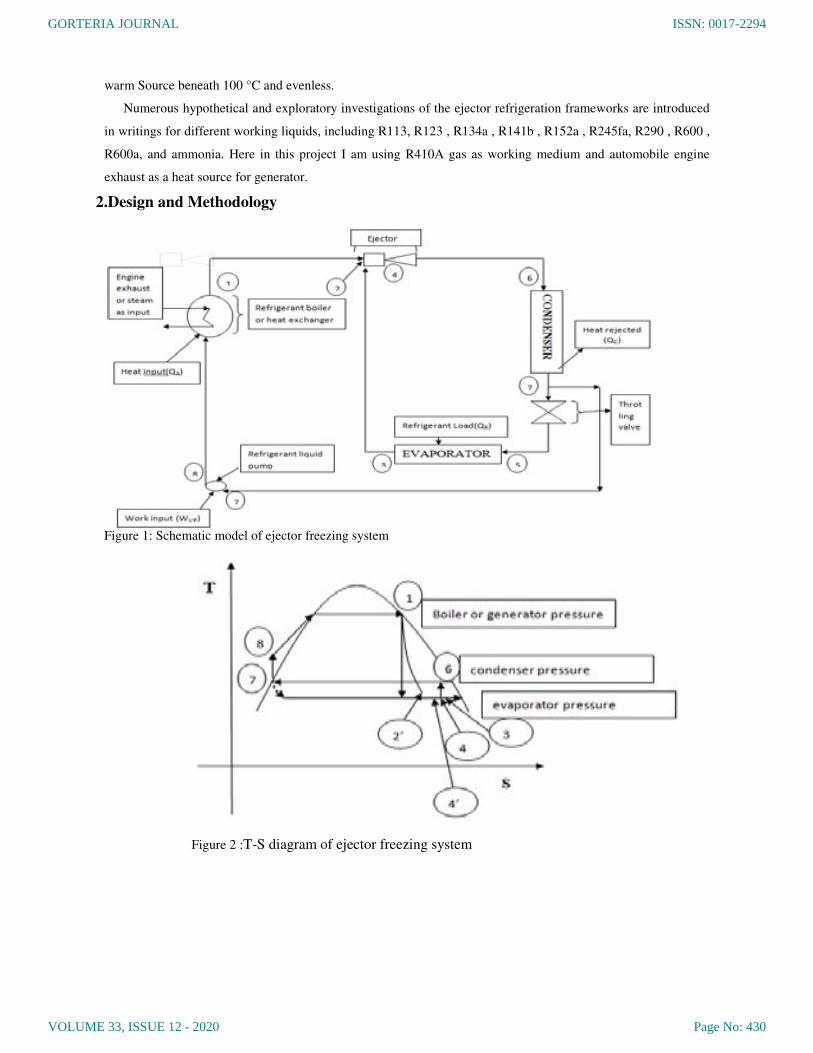
2.Design and Methodology
Figure 1: Schematic model of ejector freezing system
Figure 2 :T-S diagram of ejector freezing system
GORTERIA JOURNAL
VOLUME 33, ISSUE 12 - 2020
ISSN: 0017-2294
Page No: 430
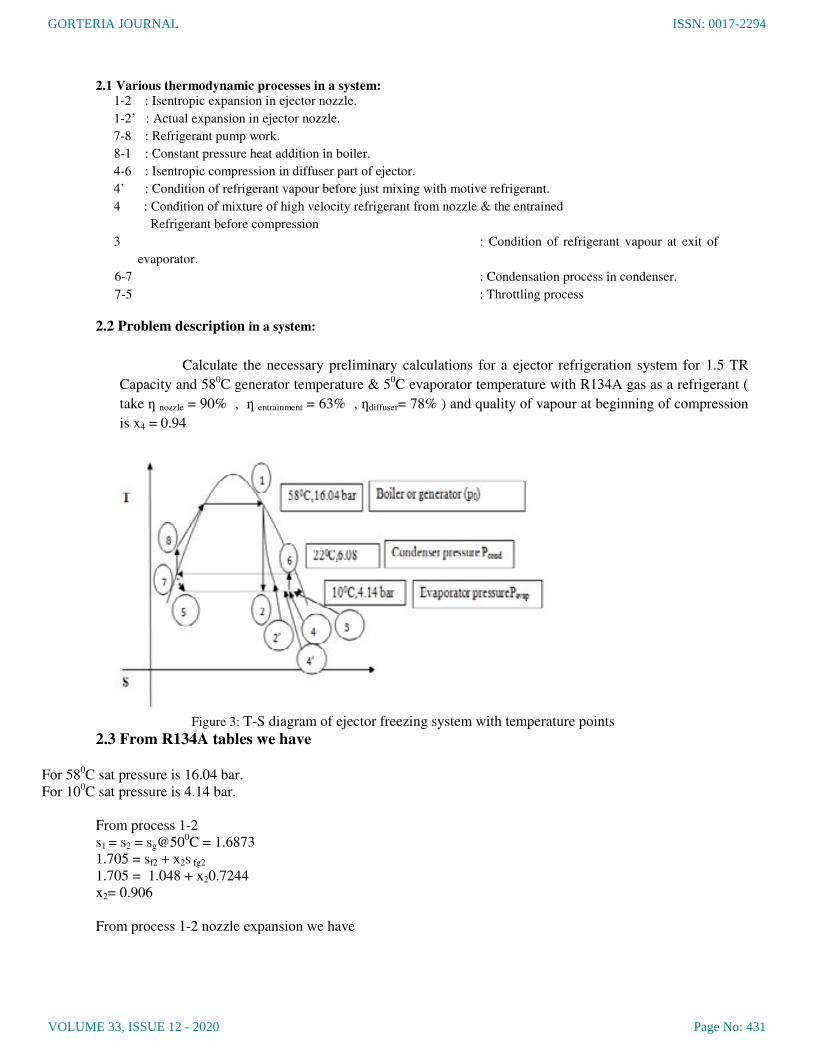
2.1 Various thermodynamic processes in a system:
1-2 : Isentropic expansion in ejector nozzle.
1-2’ : Actual expansion in ejector nozzle.
7-8 : Refrigerant pump work.
8-1 : Constant pressure heat addition in boiler.
4-6 : Isentropic compression in diffuser part of ejector.
4’ : Condition of refrigerant vapour before just mixing with motive refrigerant.
4 : Condition of mixture of high velocity refrigerant from nozzle & the entrained
Refrigerant before compression
3 : Condition of refrigerant vapour at exit of
evaporator.
6-7 : Condensation process in condenser.
7-5 : Throttling process
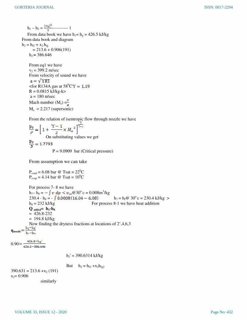
2.2 Problem description in a system:
Calculate the necessary preliminary calculations for a ejector refrigeration system for 1.5 TR
Capacity and 580C generator temperature & 5
0C evaporator temperature with R134A gas as a refrigerant (
take ƞ nozzle = 90% , ƞ entrainment = 63% , ƞdiffuser= 78% ) and quality of vapour at beginning of compression
is x4 = 0.94
Figure 3: T-S diagram of ejector freezing system with temperature points
2.3 From R134A tables we have
For 58
0C sat pressure is 16.04 bar.
For 100C sat pressure is 4.14 bar.
From process 1-2
s1 = s2 = sg@500C = 1.6873
1.705 = sf2 + x2s fg2
1.705 = 1.048 + x20.7244
x2= 0.906
From process 1-2 nozzle expansion we have
GORTERIA JOURNAL
VOLUME 33, ISSUE 12 - 2020
ISSN: 0017-2294
Page No: 431
h1 – h2 = ----------- 1
From data book we have h1= hg = 426.5 kJ/kg
From data book and diagram
h2 = hf2 + x2 hfg
= 213.6 + 0.906(191)
h2 = 386.646
From eq1 we have
v2 = 399.2 m/sec
From velocity of sound we have
<for R134A gas at 580C
R = 0.0815 kJ/kg-k>
a = 180 m\sec
Mach number (Ma) =
Ma = 2.217 (supersonic)
From the relation of isentropic flow through nozzle we have
On substituting values we get
P = 9.0909 bar (Critical pressure)
From assumption we can take
Pcond = 6.08 bar @ Tsat = 220C
Pevap = 4.14 bar @ Tsat = 100C
For process 7- 8 we have
h7– h8 = sat@30o c = 0.008m
3/kg
230.4 - h8 = - h7 = hf@ 30o c = 230.4 kJ/kg >
h8 = 232 kJ/kg For process 8-1 we have heat addition
Q added= h1-h8 = 426.8-232
= 194.8 kJ/kg
Now finding the dryness fractions at locations of 2’,4,6,3
ƞnozzle
0.90
h2' = 390.6314 kJ/kg
But h2 = hf2 +x2hfg2
390.631 = 213.6 +x2 (191)
x2= 0.906
similarly
GORTERIA JOURNAL
VOLUME 33, ISSUE 12 - 2020
ISSN: 0017-2294
Page No: 432
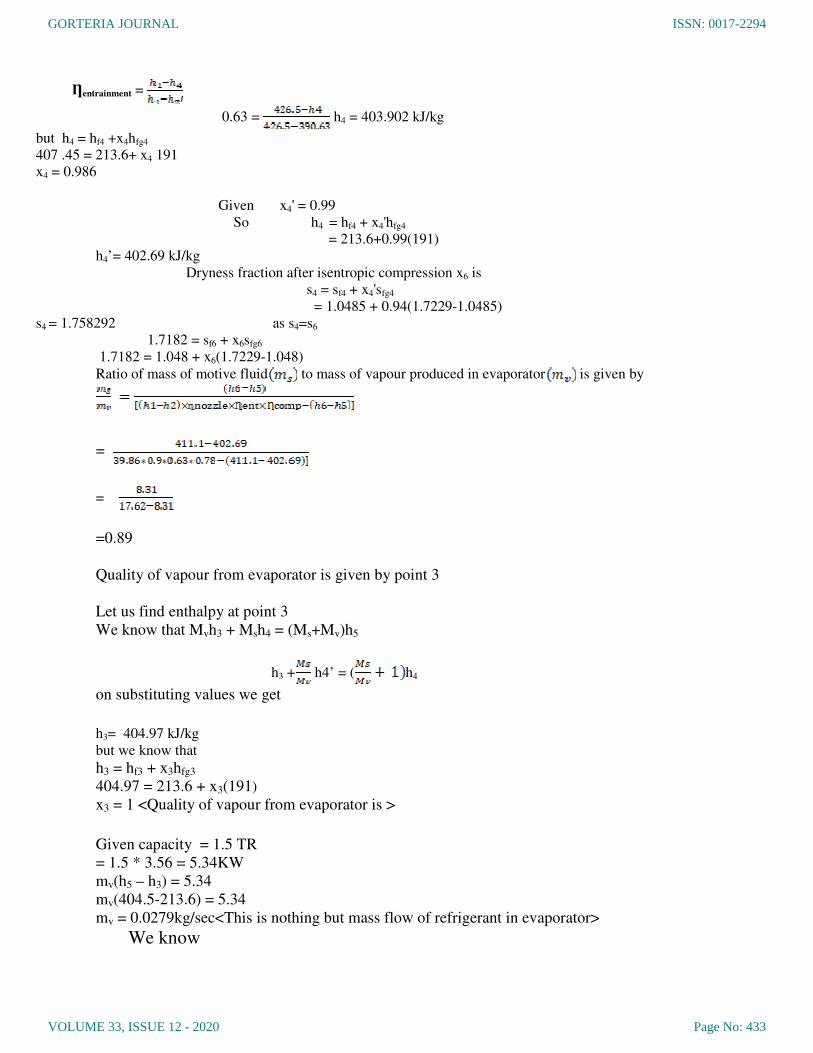
Ƞentrainment =
0.63 = h4 = 403.902 kJ/kg
but h4 = hf4 +x4hfg4
407 .45 = 213.6+ x4 191
x4 = 0.986
Given x4' = 0.99
So h4 = hf4 + x4'hfg4
= 213.6+0.99(191)
h4’= 402.69 kJ/kg
Dryness fraction after isentropic compression x6 is
s4 = sf4 + x4'sfg4
= 1.0485 + 0.94(1.7229-1.0485)
s4 = 1.758292 as s4=s6
1.7182 = sf6 + x6sfg6
1.7182 = 1.048 + x6(1.7229-1.048)
Ratio of mass of motive fluid to mass of vapour produced in evaporator is given by
=
=
=0.89
Quality of vapour from evaporator is given by point 3
Let us find enthalpy at point 3
We know that Mvh3 + Msh4 = (Ms+Mv)h5
h3 + h4’ = ( h4
on substituting values we get
h3= 404.97 kJ/kg
but we know that
h3 = hf3 + x3hfg3
404.97 = 213.6 + x3(191)
x3 = 1 <Quality of vapour from evaporator is >
Given capacity = 1.5 TR
= 1.5 * 3.56 = 5.34KW
mv(h5 – h3) = 5.34
mv(404.5-213.6) = 5.34
mv = 0.0279kg/sec<This is nothing but mass flow of refrigerant in evaporator>
We know
GORTERIA JOURNAL
VOLUME 33, ISSUE 12 - 2020
ISSN: 0017-2294
Page No: 433
= 0.899=0.89.
ms = 0.0248 kg/sec
Coefficient of performance (COP)=
Now heat added to system is = mv x 194.8 KW
= 0.0248 x 194.8
= 4.831KW
Therefore COP =
=
COP = 1.105
Similarly by doing analysis using forR410A Gas we got COP= 0.97
3.Designing Of Primary Nozzle Of Ejector
3.1From the above calculations we have
Mach number at nozzle exit ( ) = 0.724
Mass flow rate through evaporator coil ( ) =0.032 kg/sec.
Therefore mass flow rate through motive nozzle ( ) is given by
Where h6 = enthalpy of gas at outlet of ejector = 411.1 kJ/kg
h4 = enthalpy of mixture before compression = 402.69 kJ/kg
h1 = enthalpy of gas at inlet of motive nozzle = 426.5 kJ/kg
h2 = enthalpy of gas at outlet of motive nozzle = 386.64 kJ/kg
And we assumed
Therefore
= 0.89
=0.89 *Mv = 0.89*0.0274
From isentropic flow through nozzles we have (here we are using only convergent nozzle so
even though there is supersonic flow we restrict to only sonic so we put Mach number( ).
= 0.024389 kg/sec
GORTERIA JOURNAL
VOLUME 33, ISSUE 12 - 2020
ISSN: 0017-2294
Page No: 434

A = 5.248e-6
= 5.248e-6
D =2.57mm= D2
(This is out let diameter of converging nozzle)
From continuity equation we have:
ρAV= constant
ρ1A1V1= ρ2A2V2where ρ1 = Density of refrigerant at entryof motive nozzle
A1 = Area of cross section at entryof motive nozzle
V1 = Inlet velocity of motive Nozzle (5m/s)
Similarlyρ2, A2,V2 are corresponding parametersat exit
We have
=
= 1.6122
1.6122*A1V1= A2V2
1.6122*5* A1= A2*180
= 22.329
D2 = 2.57mm
D1 = 12.144 mm
GORTERIA JOURNAL
VOLUME 33, ISSUE 12 - 2020
ISSN: 0017-2294
Page No: 435
D1=Diameter of the nozzle at entrance
3.2 Diameter of Secondary Inlet(SUCTION PIPE)
The pressure at the secondary inlet (suction pipe) is 6bar
We have the formula for pressure isP = where
600000 = 82.71*9.81*h =density of fluid = 82.71kg/m3
V = velocity of fluid
A = cross section area of tube
We know that velocity of flow
V =
=
V = 120.4513 m/s
Therefore from formula of mass flow rate we have M =
0.032 = 82.71 * * 120.4531
3.3 Diameter of Mixing Chamber
From continuity equation we have
ρ2A2V2 = ρ3A3V3+ ρ4A4V4
Where as we know that ρ2= ρ3 = ρ4ρ4= Density of refrigerant inmixing section
Take V4=100m/s i.e average of nozzle outlet and secondary inlet velocities A4= Area of cross
section ofMixing section
V4 =Velocity in the mixingsection
Similarly ρ3,A3 ,V3 are corresponding parameterssecondary inlet
(2.57 * 10-3
)2 * 180 = (2.02*10
-3)2*120 + D
24*100
3.4 LengthOfthe Mixing Chamber
From correlation established by R.A.Tyler and R.G.Williamson by experimentation, we have
L0 (initial mixing length) = 4.2*(1- )5/3
*(1- )-1
WhereV0 = secondary inlet velocity ofFluid
Vi = velocity of fluid at nozzle
L(total length) = L0 +
K= 0.75*(1- )2.5
*
h= 739.476 m
D3 = 2.02mm
D4 = 4.0959 mm
GORTERIA JOURNAL
VOLUME 33, ISSUE 12 - 2020
ISSN: 0017-2294
Page No: 436
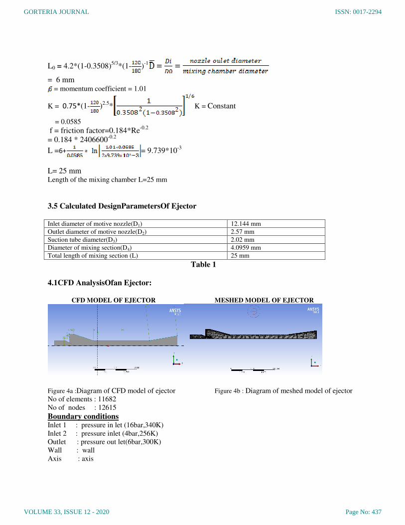
L0 = 4.2*(1-0.3508)5/3
*(1- )-1 = =
= 6 mm = momentum coefficient = 1.01
K = 0.75*(1- )2.5
* K = Constant
= 0.0585
f = friction factor=0.184*Re-0.2
= 0.184 * 2406600-0.2
L =6+ = 9.739*10-3
L= 25 mm Length of the mixing chamber L=25 mm
3.5 Calculated DesignParametersOf Ejector
Inlet diameter of motive nozzle(D1) 12.144 mm
Outlet diameter of motive nozzle(D2) 2.57 mm
Suction tube diameter(D3) 2.02 mm
Diameter of mixing section(D4) 4.0959 mm
Total length of mixing section (L) 25 mm
Table 1
4.1CFD AnalysisOfan Ejector:
CFD MODEL OF EJECTOR MESHED MODEL OF EJECTOR
Figure 4a :Diagram of CFD model of ejector Figure 4b : Diagram of meshed model of ejector
No of elements : 11682
No of nodes : 12615
Boundary conditions Inlet 1 : pressure in let (16bar,340K)
Inlet 2 : pressure inlet (4bar,256K)
Outlet : pressure out let(6bar,300K)
Wall : wall
Axis : axis
GORTERIA JOURNAL
VOLUME 33, ISSUE 12 - 2020
ISSN: 0017-2294
Page No: 437

Viscous K- model Contours of pressure
Contours of velocity Pressure vs axial distance of ejector
Figure 5 :A .Diagram of Viscous K- modelof ejector,B. Contours of pressure, C.Contours of velocity D.
Pressure vs axial distance of ejector
4.2 Variation of mass flow(Ms) according to percentage change of back pressure(Pb) with
respect to secondary inlet pressure(Ps)
Table 2
4.3 Entrainment ratio(ER) vs(Pb-Ps)/Ps
Figure 6 :Graph showsEntrainment ratio(ER) between (Pb-Ps)/Psof an ejector
S.No Inlet Pressure1
(bar)
Inlet Pressure 2
(bar)
Outlet
pressure
(bar)
Primary mass
flow(kg/s)
(Mp)
Secondary mass
flow(kg/s)
(Ms)
Entrainment
ratio(Ms/Mp)
1 16 4 6 0.0424 0.039 0.928
2 16 4 5 0.0426 0.1056 2.38
3 16 4 3 0.0429 0.2346 5.468
4 16 4 2 0.043 0.2914 6.776
GORTERIA JOURNAL
VOLUME 33, ISSUE 12 - 2020
ISSN: 0017-2294
Page No: 438

5. Conclusions:
Chillers are very effective components in the process of refrigeration. While absorption chillers
have dominated the market, ejector chillers are also picking up. Most important constraint in choosing the
chiller is the cost component. In case of absorption chillers, they have been found to be cost effective.
While the ejector chillers performance has been found to be smooth, there has to be cost rationalisation.
In any project analysis, cost component plays an important role hence the need for economising the input
components.
Once cost rationalization is achieved, the ejector chiller can occupy the market space slowly being
vacated by absorption chiller. But for this to be achieved ejector chillers need to become cost competitive
through an increase in the system COP, that involves reduced size of heat changers and the plant. Once
this happens ejector chillers can make a niche for themselves, in the heat powered refrigeration market.
In the refrigeration process the delivery efficiency depends upon the ejector performance. While cost
efficiency needs to be achieved, performance efficiency should not be compromised. While the
performance requires low cost robust operation and absolute safety standards,
It is in this context that efforts to enhance ejector efficiency were initiated and analysed in the paper.
Results indicate that the performance of refrigeration system is exponentially influenced by incremental
improvements in ejector performance. The process has been done duly considering cost effectiveness,
robustness of operational performance, standard environmental practices. The research indicates steam-
based systems to be more suitable for large scale industrial environments, while small systems could be
powered synthetic fluids.
There is a need for further advanced research to develop analytical tools and mathematical models to
understand thr complexity and dynamics of thermodynamics. Precessual dynamics of various boundary
layers also need to be understood to draw reliable and repeatable conclusions.
To conclude, improvisation of systemic designs focusing on Supersonic Steam ejectors and vapour
compression systems coupled with multi-dimensional flow analysis could be a viable testing ground for
examining further applications.
6. REFRERENCES:
1. A journal of Proposal and thermodynamic analysis of an ejection–compression
refrigeration cycle driven by low-grade heat.
2. A journal of simulation on the performance of ejector in a parallel hybrid ejector-based refrigerator-freezer
cooling cycle.
3. A journal on performance investigation of a novel EEV-based ejector for refrigerator – freezers
4. Ersoy H.K., Sag N.B Preliminary experimental results on the R134a refrigeration system using a two-phase
ejector as an expander, International Journal of Refrigeration
5. Wang F., Li D.Y., Zhou Y., (2016), Analysis for the ejector used as expansion valve
in vapor compression refrigeration cycle
6. Chen, J., Havtun, H., Palm, B., Screening of working fluids for the ejector refrigeration system
7. Milazzo, A., Rocchetti A., Modelling of ejector chillers with steam and other working fluids. Int. J. Refrig.
GORTERIA JOURNAL
VOLUME 33, ISSUE 12 - 2020
ISSN: 0017-2294
Page No: 439

8. Eames I.W., Worall M., Wu S., Experimental investigation into the integration of jet-pump refrigeration cycle and
a novel jet-spay thermal ice storage system
9. Eames, I.W., A new prescription for the design of supersonic jet-pumps: the constant rate of momentum change
method.
10.Mazzelli F., Brezgin D., Murmanskii I., Zhelonkin N., Milazzo A., Condensation in supersonic steam ejectors:
comparison of theoretical and numerical models, 9th International Conference on Multiphase Flow.
11.Grazzini G., Mazzelli F., Milazzo A., Constructal design of the mixing zone inside a supersonic ejector, Int. J. of
Heat and Technology.
GORTERIA JOURNAL
VOLUME 33, ISSUE 12 - 2020
ISSN: 0017-2294
Page No: 440