Analysenmesssystem Process Analysis System Protos 3400(X) · The Protos 3400(X) is an expandable...
108
Latest Product Information: www.knick.de Protos 3400(X) Process Analysis System The Art of Measuring. User Manual English Measuring Module Protos COND 3400(X)-041 For Conductivity Measurement with 2- or 4-Electrode Sensors
-
Upload
duongduong -
Category
Documents
-
view
222 -
download
0
Transcript of Analysenmesssystem Process Analysis System Protos 3400(X) · The Protos 3400(X) is an expandable...

Latest Product Information: www.knick.de
Protos 3400(X) Process Analysis System
The Art of Measuring.
Aktuelle Produktinformation: www.knick.de
Analysenmesssystem Protos 3400(X)
Betriebsanleitung Messmodul Protos CONDI 3400 (X)-051 zur Leitfähigkeitsmessung mit induktiven SensorenDeutsch
The Art of Measuring.
Aktuelle Produktinformation: www.knick.de
Analysenmesssystem Protos 3400(X)
Betriebsanleitung Messmodul Protos CONDI 3400 (X)-051 zur Leitfähigkeitsmessung mit induktiven SensorenDeutsch
User ManualEnglish
Measuring Module Protos COND 3400(X)-041For Conductivity Measurement with2- or 4-Electrode Sensors

TrademarksThe following trademarks are used in this manual without further marking:
CalCheck®, Calimatic®, Protos®, Sensocheck®, Sensoface®, ServiceScope®, Unical®, VariPower®, Ceramat®, SensoGate®are registered trademarks of Knick Elektronische Messgeräte GmbH & Co. KG, Germany
Memosens® is a registered trademark of Endress+Hauser Conducta GmbH & Co. KG, GermanyKnick Elektronische Messgeräte GmbH & Co. KG, Germany
SMARTMEDIA® is a registered trademark of Toshiba Corp., Japan
©2017 Subject to change without notice
Return of Products under WarrantyPlease contact our Service Team before returning a defective device. Ship the cleaned device to the address you have been given. If the device has been in contact with process fluids, it must be decontaminated/ disinfected before shipment. In that case, please attach a corresponding certificate, for the health and safety of our service personnel.
DisposalPlease observe the applicable local or national regulations concerning the disposal of “waste electrical and electronic equipment”.
KnickElektronische Messgeräte GmbH & Co. KGBeuckestr. 2214163 Berlin, Germany
Phone: +49 30 801 91 - 0Fax: +49 30 801 91 - 200Web: www.knick.deEmail: [email protected]

3
Table of Contents Protos COND 3400(X)-041 Module
Return of Products under Warranty .................................................................................... 2Disposal ......................................................................................................................................... 2Trademarks ................................................................................................................................... 2Intended Use ................................................................................................................................ 6Safety Information ..................................................................................................................... 7Software Version ........................................................................................................................ 8Modular Concept ....................................................................................................................... 9Short Description .......................................................................................... 10Short Description: FRONT Module ....................................................................................10Short Description: Menu Structure ....................................................................................11Short Description: BASE Module ........................................................................................13Terminal Plate COND 3400-041(X) Module ................................................. 14Inserting the Module .................................................................................... 15Wiring Examples ............................................................................................ 16Menu Selection .............................................................................................. 24Menu Structure .............................................................................................. 24Passcode Entry ............................................................................................... 25
Changing a passcode .....................................................................................................25Configuring the Measurement Display ....................................................... 26Calibration / Adjustment .............................................................................. 29Adjustment .................................................................................................................................30Temperature Compensation ................................................................................................31HOLD Function During Calibration ...................................................................................32
Manual Entry of Calibration Solution .......................................................................36Product Calibration .........................................................................................................38Data Entry of Premeasured Sensors .........................................................................40
Sensor Calibration ....................................................................................................................41Parameter Setting: Operating Levels .......................................................... 43
Administrator level .........................................................................................................43Operator level ...................................................................................................................43Viewing level .....................................................................................................................43
Parameter Setting: Locking a Function ...........................................................................44Activating Parameter Setting ..............................................................................................45Documenting Parameter Setting .......................................................................................46

4
Table of Contents Protos COND 3400(X)-041 Module
ProgaLog 3000 Software (Option) for Configuration and Documentation .......48Configuration using "ProgaLog 3000" .....................................................................51
Parameter Setting ......................................................................................... 52Default Settings and Selection Range ..............................................................................52TC Process Medium ................................................................................................................53Parameter Setting: Concentration Curves ......................................................................54Concentration Table ................................................................................................................57pH Value Calculation ..................................................................................... 58USP Function .................................................................................................. 60Configuring a Calculation Block ................................................................... 63Logbook .....................................................................................................................................64Factory setting ..........................................................................................................................64Messages: Default Settings and Selection Range ........................................................65Current Outputs, Contacts, OK Inputs ......................................................... 67Configuring the Current Output.........................................................................................67Current Outputs: Characteristics ........................................................................................68Output Filter ...............................................................................................................................70NAMUR Signals: Current Outputs ......................................................................................71NAMUR Signals: Relay Contacts ..........................................................................................72Relay Contacts: Protective Wiring ......................................................................................73Relay Contacts, Usage ............................................................................................................74Relay Contacts: Sensoface Messages ................................................................................75Rinse Contact .............................................................................................................................76Icons in the Measurement Display ....................................................................................77Limit Value, Hysteresis, Contact Type................................................................................77OK1, OK2 Inputs: Specify Level ...........................................................................................78Switching Parameter Sets via OK2 .....................................................................................79Select Parameter Set (A, B) via OK2 Input .......................................................................79Signaling Active Parameter Set via Relay Contact .......................................................79Maintenance .................................................................................................. 80

5
Diagnostics Functions ................................................................................... 81Opening the Diagnostics Menu ..........................................................................................81Point of Meas Description .....................................................................................................81Logbook .......................................................................................................................................81Device Description ..................................................................................................................82FRONT Module ..........................................................................................................................82BASE Module ..............................................................................................................................82Module Diagnostics.................................................................................................................83Sensor Monitor ..........................................................................................................................83Cal Record ...................................................................................................................................83Message list ...............................................................................................................................86Specifications ................................................................................................. 90Appendix ........................................................................................................ 95Minimum Spans for Current Outputs ...............................................................................95Index ............................................................................................................. 100Menu Selection ............................................................................................ 108
Table of Contents Protos COND 3400(X)-041 Module
6
Intended Use
The module is an input module for conductivity measurement with commer-cially available 2- or 4-electrode sensors. The COND 3400X-041 module is intended for operation in locations subject to explosion hazards which require equipment of Group II, device category 2(1), gas/dust.
Conformity with FDA 21 CFR Part 11In their directive “Title 21 Code of Federal Regulations, 21 CFR Part 11, Electronic Records; Electronic Signatures“ the US American health agency FDA (Food and Drug Administration) regulates the production and processing of electronic documents for pharmaceutical development and production. This results in requirements for measuring devices used for corresponding applica-tions. The following features ensure that the Protos 3400(X) modular process analysis system meets the demands of FDA 21 CFR Part 11:
Electronic SignatureAccess to the device functions is regulated and limited by individually adjust-able codes (“Passcodes“). This prevents unauthorized modification of device settings or manipulation of the measurement results. Appropriate use of these passcodes makes them suitable as electronic signature.
Audit Trail LogEvery change of device settings can be automatically recorded and docu-mented in the Audit Trail Log on the SmartMedia card. The recording can be encrypted.
7
Safety InformationApplication in Hazardous Locations
Caution!Never try to open the module! If a repair should be required, return the mod-ule to our factory.
If the specifications in the instruction manual are not sufficient for assessing the safety of operation, please contact the manufacturer to make sure that your intended application is possible and safe.
Be sure to observe during installation:• Switch off power supply before replacing or inserting a module.• Protect the signal inputs of the modules against electrostatic discharge.• Before commissioning it must be proved that the device may be connected
with other equipment.• Observe correct shielding.
Application in Hazardous Locations: COND 3400X-041 ModuleThe module is approved for operation in hazardous locations.Observe all applicable local codes and standards for the installation of electrical equipment in hazardous locations. For orientation, please refer to IEC 60079-14, EU directives 2014/34/EU and 1999/92/EC (ATEX), NFPA 70 (NEC), ANSI/ISA-RP12.06.01.• When installing the device in a hazardous location, observe the specifica-
tions of the EC-Type-Examination Certificate and, if applicable, of the Control Drawing (download: www.knick.de).
• Before commissioning you must prove that the device may be connected with other equipment, such as a supply unit including cables and wires.
• In hazardous locations the device shall only be cleaned with a damp cloth to prevent electrostatic charging.
• Devices and modules which have already been used shall be subjected to a professional routine test before they may be operated in another zone or another type of protection.

8
Software Version COND 3400(X)-041 Module
Device Software Protos 3400(X)The COND 3400-041 module is supported by software version 1.0 or higher. The COND 3400X-041 module is supported by software version 4.0 or higher.
Module Software COND 3400(X)-041Software version 2.x
Menu Display Device description
Device hardware and software versionProvides information on all modules installed: Module type and function, serial number, hardware and software version and device options. Select the different modules (FRONT, BASE, slots 1 - 3) using the arrow keys.
Device description
Return
22.7 °C1.225 mS/cm
Operating panel ProtosModule FRONT 3400-011
Hardware: 1.1, Software: A.2Serial number: 08150815
BASEModule FRONT
Query actual device/module softwareWhen the analyzer is in measuring mode:Press menu key, open Diagnostics menu: Device description
Options
Device description
Return
22.7 °C1.225 mS/cm
Input for 2/4-electr. sensors and °CModule COND 3400-041
Hardware: 1, Software: 2.0Serial number: 471101147
BASEModule FRONT
Options
Query module softwareModule COND 3400-041, hardware and software version, serial number – here installed in slot 3.

9
Modular ConceptBasic unit, measuring modules, additional functions
Documentation The basic unit is accompanied by a CD-ROM containing the complete documentation. Latest product information as well as user manuals for earlier software releases are available at www.knick.de.
The Protos 3400(X) is an expandable modular process analysis system.The basic unit (FRONT and BASE modules) provides three slots which can be equipped by the user with any combination of measuring or communication modules. The software capabilities can be expanded by additional functions (options). Additional functions must be ordered separately. They are supplied with a device-specific TAN for function release.
3 module slotsfor free combination of measuring and communication modules
Measuring modules• pH / ORP / Temp• O2 / Temp• Noncontacting conductivity / Temp• Contacting conductivity / Temp• Memosens sensors
Additional functionsActivation via device-specific TAN
SmartMedia cardData recording
ProgaLog 3000Windows® software for parameter setting and data evaluation
Protos 3400(X) Modular Process Analysis System
Communication modules• OUT (additional switching and current
outputs)• PID (analog and digital controller)• Profibus PA• Foundation Fieldbus• FIU (Memosens, Unical)
(software occupies 2 slots)• Unical probe controller

10
Short DescriptionShort Description: FRONT Module
Transflective LC graphic display(240 x 160 pixels)white backlighting, high resolution and high contrast.
Red LED signals failure (On) or maintenance request/function check (flashing) according to NE 44.
4 captive screwsfor opening the analyzer(NOTICE! Make sure that the gasket between FRONT and BASE is properly seated and clean!)
Green LED Voltage supply okay
5 self-sealing cable glandsM20 x 1.5for entry of voltage supply and signal lines
2 softkeys with context-sensitive functions.
User interface with plaintext menus as recom-mended by NAMUR. Menu texts can be switched to: German, English, French, Italian, Swedish/Portuguese or Spanish.Intuitively acquirable menu logic, based on Windows standards.
Control panel3 function keys (menu, meas, enter)and 4 arrow keys for menu selection and data entry
Measurement display
Secondary displays
24.0°C 25.8°C

11
Measure
Short Description: Menu StructureBasic functions: Calibration, Maintenance, Parameter setting, Diagnostics
Calibration Maintenance Parameter setting Diagnostics
Menu groups
1
2
3
1147 2958 1246Operator level
1989Administrator level
Passcode:
Selection offurthermenu items:
Module 1Module 2Module 3
BASE Module 1 Module 2 Module 3
SYSTEM FRONT BASE Module 1 Module 2 Module 3
Message listPoint of meas descriptionLogbookDevice description
FRONT BASE Module 1 Module 2 Module 3
4
5 6
Legend:1) Pressing the menu key accesses menu selection.2) Pressing the meas key returns to measurement.3) Menu groups are selected using the arrow keys4) Press enter to confirm, enter passcode5) Further menu items are displayed6) Selected functions of the Diagnostics menu can be recalled
via softkey even when in measuring mode

12
Short Description: FRONT ModuleView into the open device (FRONT module)
Terminal plates of “hidden” modulesEach module comes with an adhesive label containing the contact assignments. This label should be sticked to the inner side of the front (as shown). Then, the terminal assignments remain visible even if further modules are inserted.
Slot for SmartMedia card• Data recording
The SmartMedia card expands the measurement recorder capacity to > 50000 records.
• Exchange of parameter sets 5 parameter sets can be stored on the SmartMedia card, 2 of them can be loaded simultaneously to the analyzer and be switched by remote control. Parameter sets can be transmitted from one analyzer to the other.
• Function expansions are possible with additional software modules, which are released using transaction numbers (TAN).
• Software updates
The circumferential sealingguarantees IP 65 protection and allows spray cleaning / disinfection. Caution! Keep clean!
Replacing the front module Pull off power cord and ground wire. To separate the FRONT module from the BASE module, turn the retaining screws of the pivot hinge by 90°.
13
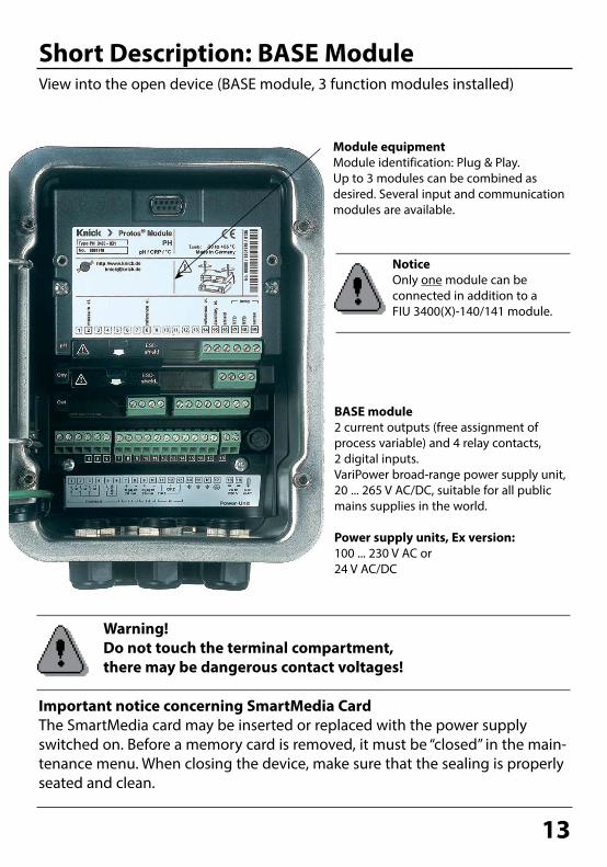
Short Description: BASE ModuleView into the open device (BASE module, 3 function modules installed)
BASE module2 current outputs (free assignment of process variable) and 4 relay contacts, 2 digital inputs. VariPower broad-range power supply unit, 20 ... 265 V AC/DC, suitable for all public mains supplies in the world.
Power supply units, Ex version:100 ... 230 V AC or 24 V AC/DC
Important notice concerning SmartMedia CardThe SmartMedia card may be inserted or replaced with the power supply switched on. Before a memory card is removed, it must be “closed” in the main-tenance menu. When closing the device, make sure that the sealing is properly seated and clean.
Module equipment Module identification: Plug & Play.Up to 3 modules can be combined as desired. Several input and communication modules are available.
Warning! Do not touch the terminal compartment, there may be dangerous contact voltages!
Notice Only one module can be connected in addition to a FIU 3400(X)-140/141 module.

14
Terminal Plate COND 3400-041(X) Module
Attaching the Terminal PlatesThe terminal plates of the lower modules can be sticked to the inner side of the door. This facilitates maintenance and service.
Terminal Plate COND 3400-041 Module:

15
Inserting the ModuleNote: Be sure to connect the shielding properly!
Switch off power supplyOpen the device (loosen the 4 screws at the front)Place module in slot (D-SUB connector)Tighten fastening screws of the moduleConnect sensor cableClose device, tighten screws at the frontSwitch on power supplySet parameters
Caution! Be sure to select the sensor type you are using in the parameter setting menu!
Make sure that the cable glands are tightly closed to protect against humidity.
1.2.3.4.5.6.7.8.

16
Wiring Example 1Conductivity measurement with 4-electrode sensor
Wiring Example 2Conductivity measurement with 2-electrode coax sensor
Wiring ExamplesNote: Be sure to connect the shielding properly!See EC-Type-Examination Certificate (www.knick.de) for Ex ratings.
COND 3400-041
COND 3400-041

17
WH
PK BN GY
BU BK GN
RD YESchaltbau connector
Wiring Example 3Conductivity measurement with SE 604 2-electrode coax sensorConnection via Schaltbau cable
Pt 1000
COND 3400-041
Schaltbau connectorPin Wire color Module terminal1 White 22 Brown 33 Green 174 Gray 45 Pink 16 Red, yellow 18 and 19A Blue 5
View on sensor

18
Brow
n
Whi
te
Shie
ld
Gre
en
Yello
w
Wiring Example 4Conductivity measurement with SE 610 2-electrode sensorConnection with pre-assembled cable with wire end ferrules
COND 3400-041
Pt 1000
Screw clamp connectionWire color Module terminalBrown 2 (jumper 1-2)White 3 (jumper 3-4-5)Shield 16Green 17Yellow 18 (jumper 18-19)

19
Wiring Example 5Conductivity measurement with SE 620 2-electrode sensorConnection with VP cable
Coax
cor
e
Gra
y
Shie
ld y
elow
/gre
en
Gre
en
Whi
te
COND 3400-041
Pt 1000
Screw clamp connectionVP cable Module terminalCoax core 1Coax shield 2 Gray 3Blue 4 (jumper 4-5)Shield 16Green 17White 18 (jumper 18-19)
Coax
shi
eld
Blue

20
BN YE GN
WH
BK GY
RD PK
GDM connector
Wiring Example 6Conductivity measurement with the SE 630 (ZU 0071) 2-electrode sensorConnection via GDM connector
COND 3400-041
Pt 1000
Plug-in connection: GDMPin Wire color Module terminal1 Gray 172 Brown and yellow 1 and 23 Red and pink 18 and 19
Green and white 3 and 4

21
Wiring Example 7Conductivity measurement with 4-electrode fringe-field sensor (SE 600/SE 603)
COND 3400-041
GY
PK BU RD BN*
WH
/GN
YE GN
YE/GN
* SE 600: Equipotential bonding, brown wire SE 603: Additional equipotential bonding electrode must be installed (or jumper 4–5)

22
Wiring Example 8Conductivity measurement with 4-electrode sensorMettler-Toledo InPro 7100 series Connection via LF-VP cable
COND 3400-041
WH
/BU W
H
BU BK
Shie
ld
Tran
spar
ent
shie
ld
RD GN
VP plug
VP plug

23
Wiring Example 8Conductivity measurement with 4-electrode sensorMettler-Toledo InPro 7100 series Connection via LF-VP cable
Wiring Example 9Conductivity measurement with 2-electrode sensorMettler-Toledo InPro 7000 series Connection via LF-VP cable
COND 3400-041
WH
/BU W
H
BU BK
Shie
ld
Tran
spar
ent
shie
ld
RD GN
VP plug
VP plug

24
12
Menu selection
Return to meas
Select: [enter]
Lingua
Menu Selection
1 Pressing menu accesses menu selection.2 Pressing meas returns to measurement.
After switching on, the analyzer performs an internal test routine and automatically detects the number and type of modules installed.Then, the analyzer goes to measuring mode.
Measure
Menu Structure
Calibration Maintenance Parameter Setting Diagnostics
Menu groups (Select using arrow keys)
1
2
3
1147 2958 1246Operator level
1989Admin. level
Passcode(as delivered)
Selection of furthermenu items:
3 Arrow keys for selecting a menu group4 enter key for confirming a selection
1
2
3
4
0.120 mS/cm25.1 °C
0.120
8.0624.0°C 25.8°C

25
Changing a passcode“Passcode entry” menuWhen this menu is opened, the analyzer displays a warning (Fig.).Passcodes (factory settings): Calibration 1147Maintenance 2958Operator level 1246Administrator level 1989
If you lose the passcodefor the Administrator level, system access will be locked! Please consult our technical support!
To enter a passcodeSelect the position using the left/right keys, then edit the number using the up/down keys. When all numbers have been entered, confirm with enter.
To change a passcode• Open the menu selection (menu)• Select parameter setting• Administrator level, enter passcode• Select System control: Passcode entry
Passcode Entry
Menu Display System control: Passcode entry
Passcode entry (Administrator)
OK
25.6 °C0.120 mS/cm
Close
cal Calibration On
maint
opl
OffIf you lose youradm passcode, systemaccess will be locked.
To change a passcodeSelect “On” using arrow keys, confirm using enter.Select the position using the left/right keys,then edit the number using the up/down keys. When all numbers have been entered, confirm by pressing enter.
Passcode entry (Administrator)25.6 °C0.120 mS/cm
cal Calibration On Off
maint Maintenance On OffChange passcode
opl Operator level
1147
On Off
Return Info

26
Configuring the Measurement DisplaySelect menu: Parameter setting/Module FRONT/Measurement display
Pressing meas (1) returns the analyzer to the measuring mode from any function. All process variables coming from the modules can be displayed. The table on the next page describes how to configure the measurement display.
Secondary displaysAdditional values, also date and time, can be displayed depending on the modules installed.
Measurement displayTypical display for 2 points of measurement: conductivity, pH.
0.1208.06
24.0°C 25.8°C
1
SoftkeysIn measuring mode, the softkeys allow selection of values for the secondary displays or control of functions (user defined).

27
Menu Display Configuring the measurement display
Configure measurement displayPress menu key to select menu.Select parameter setting using arrow keys, confirm with enter. Select:“Administrator level”: Passcode 1989(default setting).
Parameter setting:Select “Module FRONT”
Front module:Select “Measurement display”
Measurement display:Set the number of primary values (large display) to be displayed
Select process variable(s) to be dis-played and confirm with enter.
Pressing the meas key returns to mea-surement.
Menu selection
Return to meas
0.120 mS/cm25.6 °C
Select: [enter]
Lingua
Parameter setting (Administrator)System control
Return
25.6 °C
Module BASE 3400-021 Module COND 3400-041
0.120 mS/cm
Module PH 3400-032Module CONDI 3400-051
Module FRONT 3400-011
25.6°C0.120 mS/cm
1 primary value1st primary value
Viewing angle
2 primary values
Abort OK
Measurement display (Administrator)25.6 °C0.120 mS/cm
1st primary value
Viewing angle
Main display
Abort K
Main display
mS/cmΩ/cm
g/kgS/cmcm-1pH
values
2nd primary value °C
Measurement display (Administrator)
2nd primary value
Module FRONT 3400-011 (Administrator)Languages
Return
25.6 °C
Measurement recorder
0.120 mS/cm
EnglishMeasurement display

28
29
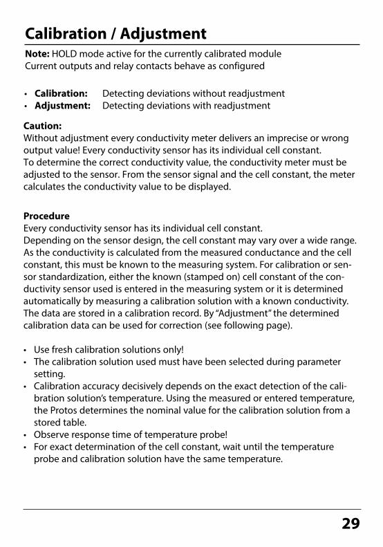
• Calibration: Detecting deviations without readjustment• Adjustment: Detecting deviations with readjustment
Calibration / AdjustmentNote: HOLD mode active for the currently calibrated module Current outputs and relay contacts behave as configured
Caution: Without adjustment every conductivity meter delivers an imprecise or wrong output value! Every conductivity sensor has its individual cell constant. To determine the correct conductivity value, the conductivity meter must be adjusted to the sensor. From the sensor signal and the cell constant, the meter calculates the conductivity value to be displayed.
ProcedureEvery conductivity sensor has its individual cell constant.Depending on the sensor design, the cell constant may vary over a wide range. As the conductivity is calculated from the measured conductance and the cell constant, this must be known to the measuring system. For calibration or sen-sor standardization, either the known (stamped on) cell constant of the con-ductivity sensor used is entered in the measuring system or it is determined automatically by measuring a calibration solution with a known conductivity. The data are stored in a calibration record. By “Adjustment” the determined calibration data can be used for correction (see following page).
• Use fresh calibration solutions only!• The calibration solution used must have been selected during parameter
setting.• Calibration accuracy decisively depends on the exact detection of the cali-
bration solution’s temperature. Using the measured or entered temperature, the Protos determines the nominal value for the calibration solution from a stored table.
• Observe response time of temperature probe!• For exact determination of the cell constant, wait until the temperature
probe and calibration solution have the same temperature.
Calibration and adjustment

30
Adjustment
Adjustmentmeans that the cell constant determined by a calibration is taken over.It is entered in the calibration record. (Cal record can be called up in the Diagnostics menu for the COND 3400(X)-041 module.) The value is only effective for calculating the measured variables when the calibration has been terminated with an adjustment.A passcode ensures that an adjustment can only be performed by an autho-rized person (Administrator).The Operator can check the current sensor data by a calibration and inform the Administrator when there are deviations.You can use the additional function SW 3400-107 for granting access rights (passcodes) and for “Audit Trail” (continuous data recording and backup accord-ing to FDA 21 CFR Part 11).
Operator (without administrator rights)After calibration, change to measuring mode. Inform Administrator.When opening the menu (Calibration, respective module), the Administrator sees all data of the last calibration and can take over the values or perform a new calibration.
Calibration data record
Cal mode
25.6 °C0249 mS/cm
Conductivity
Automatic
0249 mS/cm
End Adjust
Calibration
Cal temp
31.03.10 12:30
25.6 °C
Menu Display Adjustment after calibration
AdministratorWith the corresponding access rights, the device can immediately be adjust-ed after calibration. The calibration values are taken over for calculating the measured variables.
Module COND 3400-041
Return
25.6°C
View/adjust calibration data record
0249 mS/cm
Start new calibration
Stored calibration data record Calibration 31.03.10 12:30
Cell constant 2.7450 /cm
Adjustment

31
Calibration / AdjustmentTemperature Compensation
For automatic cal temp detection, the Protos measures the temperature of the calibration solution with a temperature probe (Pt 100 / Pt 1000 / NTC 30 kΩ). If you work with automatic temperature compensation during calibration, a temperature probe connected to the tem-perature input of the Protos must be in the calibration solution! Otherwise, you must select
manual entry of calibration temperature. When ”Cal temp automatic” is set, ”Measured cal temp” appears in the menu.
Temperature Compensation During Calibration
Calimatic
Return
Dip sensor in cal solution then “Start” calibration.Cal solution NaCl saturatedTC automatically considered
Measured cal temp
25.6 °C0249 mS/cm
+025.6 °C
ProceedSensor replacement
Manual Temperature Compensation
Automatic Temperature Compensation
The temperature of the calibration solution must be entered manually in the Calibration menu. When ”Cal temp automatic” is set, ”Measured cal temp” appears in the menu. When ”Cal temp manual” is set, ”Enter cal temp” appears in the menu.
Calimatic
Return
Dip sensor in cal solution then “Start” calibration.Cal solution NaCl saturatedTC automatically considered
Enter cal temp
25.6 °C0249 mS/cm
+025.6 °C
Proceed
Sensor replacement
The conductivity value of the calibration solution is temperature-dependent. For calibration, the calibration solution temperature must therefore be known in order to choose the actual value from the conductivity table.During parameter setting you define whether cal temperature is measured automatically or must be entered manually.
Temperature compensation

32
Calibration method
HOLD Function During CalibrationBehavior of the signal and relay outputs during calibration
Measuring
Calibration
Module AModule B
Selecting the measuring module
K2 contact "HOLD" is
active
Module A Calibration
Module B Calibration
End of calibration
(or abort)
Measuring
The current output of
the selected module
is in "HOLD" mode,
indicated by:
33
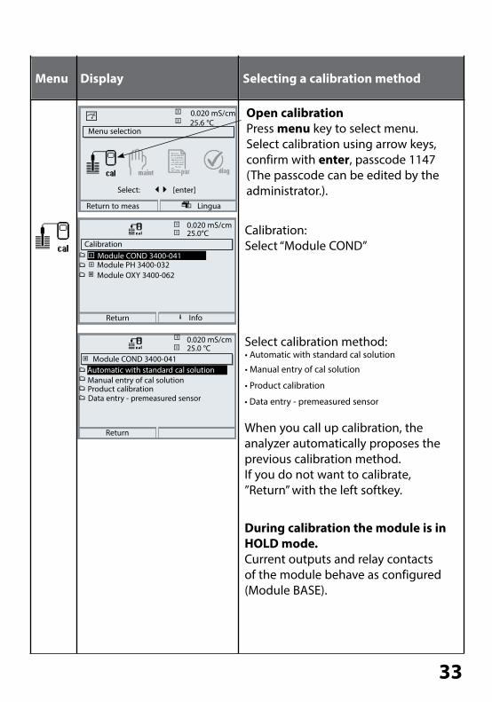
Menu Display Selecting a calibration method
Open calibrationPress menu key to select menu. Select calibration using arrow keys, confirm with enter, passcode 1147(The passcode can be edited by the administrator.).
Calibration:Select “Module COND”
Menu selection
Return to meas
0.020 mS/cm25.6 °C
Select: [enter]
Lingua
Calibration
Return
25.0°C
Module PH 3400-032
Info
0.020 mS/cm
Module COND 3400-041
Return
25.0 °C0.020 mS/cm
Manual entry of cal solutionProduct calibrationData entry - premeasured sensor
Automatic with standard cal solution
Select calibration method:• Automatic with standard cal solution
• Manual entry of cal solution
• Product calibration
• Data entry - premeasured sensor
When you call up calibration, the analyzer automatically proposes the previous calibration method. If you do not want to calibrate, ”Return” with the left softkey.
During calibration the module is in HOLD mode.Current outputs and relay contacts of the module behave as configured (Module BASE).
Module COND 3400-041
Module OXY 3400-062

34
Calibration / AdjustmentAutomatic Calibration with Standard Calibration Solution
Automatic with Standard Calibration SolutionFor automatic calibration, the conductivity sensor is immersed in a standard calibration solution (NaCl or KCl, selected during parameter setting). From the measured conductance and temperature, the Protos automatically calculates the cell constant. The temperature dependence of the calibration solution is taken into account.
During calibration the module is in HOLD mode.Current outputs and relay contacts of the module behave as configured (Module BASE).
Caution!• Use fresh calibration solutions only! The calibration solution used must have
been selected during parameter setting.• Calibration accuracy decisively depends on the exact detection of the cali-
bration solution’s temperature. Using the measured or entered temperature, the Protos determines the nominal value for the calibration solution from a stored table.
• Observe response time of temperature probe!• For exact determination of the cell constant, wait until the temperature
probe and calibration solution have the same temperature.
Be sure to observe during calibration:• If the measured conductance or the measured temperature fluctuate greatly,
the calibration procedure is aborted after 2 min.• If an error message appears, you have to repeat calibration.
Adjustment: Taking over the values determined by calibration• When the values determined by calibration are correct, they must be taken
over to adjust the analyzer.
Automatic calibration

35
Menu Display Automatic calibration
Select calibration menuSelect “Module COND”
Select calibration method: “Automatic with standard cal solution”, confirm with enter.
Display of selected calibration solution.Enter process temperature, if manual temperature adjustment has been selected.Dip sensor in calibration solution.
Start calibration with softkey or enter.
Calibration is running.The display shows:• Calibration temperature• Solution table value
(conductivity in dependence on cal temperature)
• Response time
Module COND 3400-041
Return
25.0 °C0250 mS/cm
Manual entry of cal solutionProduct calibrationData entry - premeasured sensor
Automatic with standard cal solution
AutomaticDip sensor in cal solution
25.0 °C0250 mS/cm
TC automatically considered
then “Start” calibration.
Start
NaCl saturated
Return
Cal solution
AutomaticCalibration running
25.6 °C0250 mS/cm
Correction of cell constant
Calibration temp +025.0 °CSolution table valueResponse time 0003s
Enter cal temp +025.0 °C
0.020 mS/cm
RepeatEnd
Calibration data recordCalibration
25.6 °C0250 mS/cm
Cal modeCal temp
31.03.10 11:37
ConductivityCell constant
+025.6°CAutomatic
AdjustEnd
AdjustmentPress “Adjust” to take over the values determined during calibration for calculating the measured variables.
2.7450 /cm0249 mS/cm
Sensor replacement

36
Calibration / AdjustmentManual Entry of Calibration Solution
Manual Entry of Calibration SolutionFor calibration with manual entry of the calibration solution’s conductivity, the sensor is immersed in a calibration solution. Protos determines a conductivity/calibration temperature value pair. Then, the temperature-corrected conductiv-ity value of the solution must be entered. To do this, read off the conductivity for the temperature displayed from the TC table of the calibration solution. Intermediate conductivity values must be interpolated. Protos automatically calculates the cell constant.
During calibration the module is in HOLD mode.Current outputs and relay contacts of the module behave as configured (Module BASE).
Caution!• Use fresh calibration solutions only!• Calibration accuracy decisively depends on the exact detection of the cali-
bration solution’s temperature.• Observe response time of temperature probe!• For exact determination of the cell constant, wait until the temperature
probe and calibration solution have the same temperature.
Be sure to observe during calibration:• If the measured conductance or the measured temperature fluctuate greatly,
the calibration procedure is aborted after 2 min.• If an error message appears, you have to repeat calibration.
Adjustment: Taking over the values determined by calibration• When the values determined by calibration are correct, they must be taken
over to adjust the analyzer.
Manual entry of cal solution

37
Menu Display Manual entry of cal solution
Select calibration menuSelect “Module COND”
Select calibration method: “Manual entry of cal solution”,confirm with enter.
Enter process temperature, if manual temperature adjustment has been selected.Immerse sensor in cal solution.Start calibration with softkey or enter.
Enter conductivity.End calibrationwith softkey (”End”).
Calibration is running.The display shows:• Calibration temperature• Response time
Module COND 3400-041
Return
25.0 °C0.020 mS/cm
Product calibrationData entry - premeasured sensor
Automatic with standard cal solutionManual entry of cal solution
Manual entryDip sensor in cal solutionthen `Start` calibration
24.9 °C0.020 mS/cm
StartReturn
Measured cal temp +24.9°C
Manual entryCalibration runningDetermine pair of cond/°C values
24.9 °C0.020 mS/cm
Calibration temperature +24.9°CResponse time 0001s
Manual entry25.0 °C0.020 mS/cm
EndRepeat
Conductivity
Enter calibration solution
Measured cal tempfor correct temperature!
+025.0 °C
0251 mS/cm
Sensor replacement
Calibration data recordCalibration
25.6 °C0250 mS/cm
Cal modeCal temp
31.03.10 11:37
ConductivityCell constant
+025.6°CManual input
AdjustEnd
AdjustmentPress “Adjust” to take over the values determined during calibration for calculating the measured variables.
2.7450 /cm0249 mS/cm
38
Calibration / AdjustmentProduct Calibration
Product CalibrationWhen the sensor cannot be removed, e.g. for sterility reasons (for biotechnical processes), its cell constant can be determined with “sampling”.To do so, the currently measured process value is saved by the Protos.Immediately afterwards, you take a sample from the process. The sample value should be measured at process conditions (same temperature!). The deter-mined value is entered in the measuring system. From the difference between process value and sample value, the Protos calculates the cell constant of the conductivity sensor.
During calibration the module is in HOLD mode.Current outputs and relay contacts of the module behave as configured (Module BASE).
• Product calibration without TC correctionTake a sample from the process. Measure its value at the temperature at which the sample has been taken (“Sample temp“, see display). To do so, it may be necessary to thermostat the sample correspondingly in the lab. Temperature compensation must be turned off at the comparison meters (TC = 0 %/K).• Product calibration with TC correction Tref = 25 °CTake a sample from the process. When measuring in the lab (TC linear), be sure that the same values are set for reference temperature and temperature coef-ficient in the comparison meter and in the Protos. Furthermore, the measur-ing temperature should correspond to the sample temperature (see display). Transport the sample in an insulated container (Dewar).
Caution!Product calibration can only be performed if the process medium is stable. That means, for example, that there are no chemical reactions which have an effect on the process conductivity. At higher temperatures, the sample values can also be invalidated due to evaporation.
Product calibration

39
Menu Display Product calibration
Select calibration menuSelect “Module COND”
Calibration method: “Product calibration”,confirm with enter.
Step 1Take sample.Store measured value and tem-perature at the moment of sampling (“Save” softkey or enter)The analyzer automatically returns to calibration mode selection.Press meas to return to measure-ment.
Exception:Sample value can be measured on the site and be entered immediately. To do so, press “Input” softkey.
Step 2Lab value has been measured. When you open the Product calibration menu again, the display shown on the left appears: Enter reference value (“Lab value”). Confirm with “OK” or repeat calibration.
Module COND 3400-041
Return
25.0 °C0249 mS/cm
Data entry - premeasured sensor
Automatic with standard cal solutionManual entry of cal solutionProduct calibration
Product calibrationCal medium: ProductCal by taking sample
25.0 °C0249 mS/cm
StartReturn
and entering conductivity
Product calibrationStep 1: Sampling“Save” the sample value
25.0 °C0249 mS/cm
SaveInput
“Input” lab valueConductivityTemperature
0.000µS/cm 25.0 °C
Product calibrationStep 2: Lab valueInput sample lab value
25.0 °C0249 mS/cm
OKAbort
Lab value 0.249mS/cm
without temp compensation
Calibration data recordCalibration
25.6 °C0250 mS/cm
Cal modeCal temp
31.03.10 11:37
ConductivityCell constant
+025.6°CProduct calibration
AdjustEnd
AdjustmentPress “Adjust” to take over the values determined during calibration for calculating the measured variables.
2.7450 /cm0249 mS/cm
Sensor replacement

40
Calibration / AdjustmentData Entry of Premeasured Sensors
Data Entry of Premeasured SensorsEntry of cell constant and zero point of a sensor, related to 25°C, 1013 mbars.
During calibration the module is in HOLD mode.Current outputs and relay contacts of the module behave as configured (Module BASE).
Menu Display Data entry premeasured sensors
Select module: CONDDuring calibration, the output currents (1 and 2), limit contacts, and controller output are in HOLD mode. Confirm with enter
Select calibration method“Data entry”
Confirm with enter
Enter cell constant of premeasured sensor.Confirm with “OK” or repeat calibration.
Calibration
Return
25.0°C
Module PH 3400-032
Info
0.225 mS/cm
Module OXY 3400-062Module COND 3400-041
Module COND 3400-041
Return
25.0 °C0.225 mS/cm
Product calibration
Automatic with standard cal solutionManual entry of cal solution
Data entryTemperature
25.6 °C0.225 mS/cm
Conductivity+25.6°C0.225 mS/cm
Data entry - premeasured sensor
Cell constant 1.000
End
Sensor replacement
Data entry of premeasured sensors
OK

41
Sensor CalibrationSince the cell constant is subject to production-related variances, the dismount-ed sensor should be calibrated with a calibration solution (e.g. NaCl saturated).The cell constant of the sensor – particularly of a fringe-field sensor – depends on the type of installation:• When the sensor is mounted in a free space (minimum distances exceeded),
the cell constant can be entered directly as given in the specifications. Calibration method: “Data entry”
• When mounted in restricted space (minimum distances not kept), the sensor must be calibrated when mounted since the resulting cell constant has changed. Calibration method: “Product calibration”.
SE 630 SensorThe SE 630 sensor can be calibrated automatically or manually. A suitable calibration solution is 0.01 mol/l NaCl, for example.
SE 604 SensorThe SE 604 sensor must be calibrated with direct input of the cell constant since calibration solutions in the µS/cm range are not stable.
CalibrationCalibrating the Sensors
Calibrating the sensors

42

43
Menu Display Viewing level, Operator level, Administrator level
Open parameter settingFrom the measuring mode:Press menu key to select menu.Select parameter setting using arrow keys, press enter to confirm.
Administrator levelAccess to all functions, also passcode setting.Releasing or blocking a function for access from the Operator level.
Parameter Setting: Operating LevelsViewing level, Operator level, Administrator levelNote: HOLD mode (Setting: BASE module)
Functions which can be blocked for the Operator level are marked with the "lock" symbol.The functions are released or blocked using the softkey.
Operator levelAccess to all functions which have been released at the Administrator level. Blocked functions are displayed in gray and cannot be edited (Fig.).
Viewing levelDisplay of all settings. No editing possible!
Menu selection
Return to meas
25.6 °C0.120 mS/cm
Select: [enter]
Lingua
Parameter setting
Return
25.6 °C0.120 mS/cm
Viewing level
Administrator level (All Data) adm(Operation Data) opl(All Data) view
Operator level
Module FRONT (Administrator)
Return
25.6 °C0.120 mS/cm
LanguagesMeasurement display
KI recorder
English
Measurement recorder
Release
Module FRONT
Return
25.6 °C0.120 mS/cm
Measurement display
KI recorder
English
Measurement recorder
Languages
Parameter setting
44
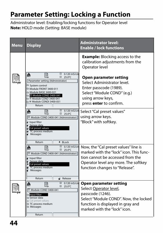
Menu Display Administrator level:Enable / lock functions
Example: Blocking access to the calibration adjustments from the Operator level
Open parameter settingSelect Administrator level. Enter passcode (1989).Select “Module COND” (e.g.) using arrow keys,press enter to confirm.
Parameter Setting: Locking a Function Administrator level: Enabling/locking functions for Operator levelNote: HOLD mode (Setting: BASE module)
Select “Cal preset values” using arrow keys. “Block” with softkey.
Now, the “Cal preset values” line is marked with the “lock” icon. This func-tion cannot be accessed from the Operator level any more. The softkey function changes to “Release”.
Open parameter settingSelect Operator level, passcode (1246).Select “Module COND”. Now, the locked function is displayed in gray and marked with the “lock” icon.
Module COND 3400-041 (Administrator)25.0°C
Return
Sensor dataCal preset values
0.120 mS/cm
MessagesTC process medium
Input filter
BLock
Parameter setting (Administrator)25.0°C
Return
Module FRONT 3400-011Module BASE 3400-021
0.120 mS/cm
System control
Module COND 3400-041Module CONDI 3400-051
Module COND 3400-041
Module COND 3400-041 (Administrator)25.0°C
Return
Sensor dataCal preset values
0.120 mS/cm
MessagesTC process medium
Input filter
Release
Module COND 3400-04125.0°C
Return
Sensor dataCal preset values
0.120 mS/cm
MessagesTC process medium
Input filter

45
Menu Display Parameter setting
Activating parameter settingFrom the measuring mode:Press menu key to select menu.Select parameter setting using arrow keys, press enter to confirm.Passcode as delivered: 1989
Select module,press enter to confirm.
(In the Figure, the "Module COND" is selected, for example.)
Select parameter using arrow keys, press enter to confirm.
Menu selection
Return to meas
25.0°C
Select: [enter]
Lingua
0.120 mS/cm
Parameter setting (Administrator)25.0°C
Return
Module PH 3400-032
Module FRONT 3400-011Module BASE 3400-021
0.120 mS/cm
System control
Module COND 3400-041Module COND 3400-041
Module COND 3400-041 (Administrator)25.0°C
Return
TC process medium
Sensor dataCal preset values
0.120 mS/cm
Messages
Input filter
Block
During parameter setting the analyzer is in HOLD mode:Current outputs and relay contacts behave as configured (BASE module).
Activating Parameter SettingActivating parameter setting

46
You must reproducibly document all parameter settings in the device to achieve a high level of system and device security according to GLP. For that purpose, an Excel file is provided (on the CD-ROM shipped with the basic device) to enter the parameter settings.
The Excel file provides one worksheet for each module with columns for the following parameters: Factory settings, parameter set A, parameter set B.Enter your settings as parameter set A or B. The gray cells in the parameter set B column cannot be modified since they contain sensor-specific values which cannot be changed by parameter set switchover. Here, the values listed under parameter set A apply.
Documenting Parameter Setting
Documenting

47
Documenting Parameter Setting
From the application window of the Excel file, select the worksheet for the module the parameter settings of which you want to document.Set the parameters of the respective module and enter the selected values in the corresponding cells of the module worksheet.
Display The "HOLD" mode is active during parameter setting.
HOLD. The NAMUR “HOLD” contact (function check) is active (factory setting: Module BASE, Contact K2, N/O contact). Current output response is user-defined: • Current meas.: The currently measured value appears at the current output • Last usable value: The last measured value is held at the current output• Fixed 22 mA: The output current is at 22 mA
NOTICE!
48
ProgaLog 3000 Software (Option) for Configuration and Documentation
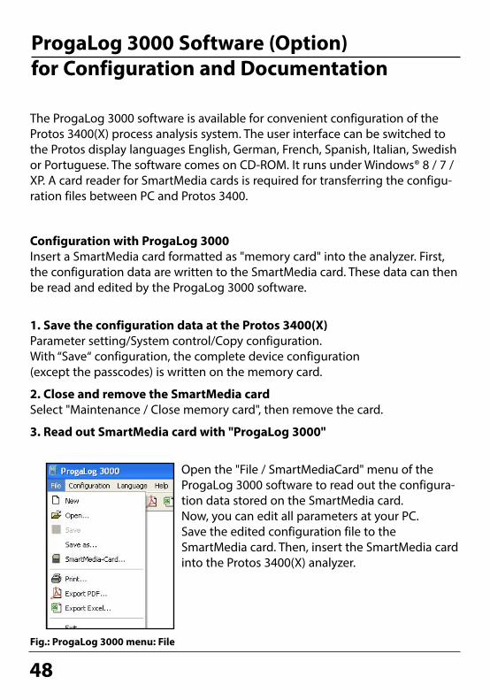
Fig.: ProgaLog 3000 menu: File
The ProgaLog 3000 software is available for convenient configuration of the Protos 3400(X) process analysis system. The user interface can be switched to the Protos display languages English, German, French, Spanish, Italian, Swedish or Portuguese. The software comes on CD-ROM. It runs under Windows® 8 / 7 / XP. A card reader for SmartMedia cards is required for transferring the configu-ration files between PC and Protos 3400.
Configuration with ProgaLog 3000Insert a SmartMedia card formatted as "memory card" into the analyzer. First, the configuration data are written to the SmartMedia card. These data can then be read and edited by the ProgaLog 3000 software.
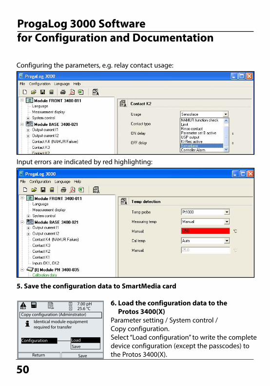
1. Save the configuration data at the Protos 3400(X)Parameter setting/System control/Copy configuration.With “Save“ configuration, the complete device configuration (except the passcodes) is written on the memory card.
2. Close and remove the SmartMedia cardSelect "Maintenance / Close memory card", then remove the card.
3. Read out SmartMedia card with "ProgaLog 3000"
Open the "File / SmartMediaCard" menu of the ProgaLog 3000 software to read out the configura-tion data stored on the SmartMedia card.Now, you can edit all parameters at your PC. Save the edited configuration file to the SmartMedia card. Then, insert the SmartMedia card into the Protos 3400(X) analyzer.

49
ProgaLog 3000 Software for Configuration and Documentation
Fig.: ProgaLog 3000 configuration data
4. Edit configuration data using ProgaLog 3000When the configuration data have been loaded, the software lists the connected modules with all available configuration parameters:
The parameters are listed according to the modular device structure. All configuration parameters (except the "Sensor data details", which are deter-mined by digital sensors) can be edited at the PC.After having finished the configuration, save the data to the SmartMedia card.
50Return
25.6 °C7.00 pH
Identical module equipment required for transfer
Copy configuration (Adminstrator)
Save
SaveConfiguration Load
6. Load the configuration data to the Protos 3400(X)
Parameter setting / System control / Copy configuration.Select “Load configuration” to write the complete device configuration (except the passcodes) to the Protos 3400(X).
ProgaLog 3000 Software for Configuration and Documentation
Input errors are indicated by red highlighting:
Configuring the parameters, e.g. relay contact usage:
5. Save the configuration data to SmartMedia card

51
ProgaLog 3000 Software for Configuration and Documentation
Configuration using "ProgaLog 3000"In the "Configurator" menu you can preconfigure a complete Protos 3400(X) process analysis system with up to 3 modules at your PC.
1. Select your configuration from the modular system components offered in the left-hand field.
2. Click the right arrow (-->) to add the components or remove components by clicking (<--).
3. Now configure the parameters for the selected system components.4. Save the configuration. You can save the configuration to a memory card that has been pre-
formatted in the Protos 3400(X) and transfer them to analyzers with identi-cal module configurations.

52
Parameter Default Selection / Range
Off, OnInput filter• Pulse suppression Off
Sensor data• Sensor type
• Nominal cell constant• Temperature detection
Measuring temp Cal temp• Sensocheck
Other 2-EL sensor
1.0000 cm-1
Pt 1000
AutoAutoOff
Cal preset values• Calibration solution
• Product calibration
NaCl 0.01 mol/l NaCl 0.1 mol/lNaCl saturatedKCl 0.01 mol/lKCl 0.1 mol/lKCl 1 mol/l
without TC, with TC
NaCl sat
without TC
Off, linear, EN 27888, ultrapure water(Linear: Enter reference temp +025.0 °C)(Ultrapure water: NaOH, NaCl, HCl, NH3)(Adjustment range depending on parameter)
TC process medium• TC correction• Reference temp• Impurity
Off
Other 2-El sensor, Other 4-El sensorSensor SE 600, Sensor SE 602, Sensor SE 603,Sensor SE 604,Sensor SE 610, Sensor SE 620, Sensor SE 630,
X.XXXX (entry) depending on selected sensor Pt100, Pt1000, NTC30kohm, Ni100 (sensor selection)Auto, manual: Default +25.0 °C (entry)Auto, manual: Default +25.0 °C (entry)Off, Failure, Maint. request
Parameter SettingDefault Settings and Selection RangeNote: HOLD mode active

53
Parameter SettingTC Process Medium Note: HOLD mode active
Menu Display TC process medium
TC process mediumYou can choose from:• Linear (input of TC coefficient)• EN 27888• Ultrapure water
(add. function SW 3400-008)
Module COND 3400-041 (Administrator)
Return
TC process medium
Sensor dataCal preset values
Messages
Input filter
Block
TC process medium (Administrator)20.1 °C
Abort
TC OffLinear
0.220 mS/cm
Ultrapure waterEN 27888
OK
TC process medium (Administrator)20.1 °C
Abort
0.220 mS/cm
OK
TC correction
0.245
20.1Outp I1 5.70 mA Favorites menu
TC
EN 27888: Natural waters (0 ... 35 °C)Ultrapure water: traces of impurity
Reference temperatureImpurity
NaOH
NH3HClNaCl
When the TC correction for process medium is switched on, “TC” appears in the display in measuring mode.
When you have selected “Ultrapure water”, you must specify the type of impurity:
NaOHAlkaline ultrapure water
NaClNeutral ultrapure water, for conductivity measurement in water processing behind gravel bed filter
HClAcidic ultrapure water, for conductiv-ity measurement behind cation filter
NH3Ammoniacal ultrapure water
20.1 °C0.220 mS/cm
54
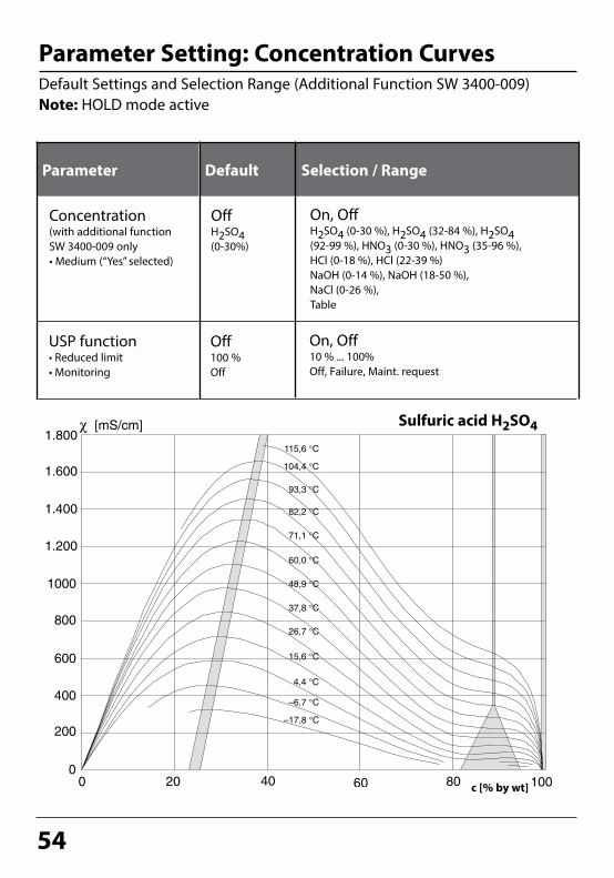
On, OffH2SO4 (0-30 %), H2SO4 (32-84 %), H2SO4 (92-99 %), HNO3 (0-30 %), HNO3 (35-96 %),HCl (0-18 %), HCl (22-39 %) NaOH (0-14 %), NaOH (18-50 %), NaCl (0-26 %),Table
Concentration(with additional function SW 3400-009 only• Medium (“Yes” selected)
OffH2SO4 (0-30%)
Parameter Default Selection / Range
Parameter Setting: Concentration CurvesDefault Settings and Selection Range (Additional Function SW 3400-009)Note: HOLD mode active
Sulfuric acid H2SO4
On, Off10 % ... 100% Off, Failure, Maint. request
USP function• Reduced limit• Monitoring
Off100 %Off
c [% by wt]

55
Nitric acid HNO3
Hydrochloric acid HClc [% by wt]
c [% by wt]

56
Sodium hydroxide solution NaOH
Table salt solution NaCl
c [% by wt]
c [% by wt]

57
Concentration TableSelect menu: Parameter setting/System control/Concentration tableSpecifying a concentration solution for conductivity measurement
Concentration TableTo specify the customer-specific solution, 5 concentration values A-E are entered in a matrix together with 5 temperature values 1-5. To do so, first enter the 5 temperature values, then enter the respective conductivity values for each concentration A-E. These solutions will then be available in addition to the permanently stored standard solutions (select “Table”).
Menu Display Enter concentration table
Enter values• Open parameter setting• System control• Select “Concentration table”
Enter 5 temperature values (right/left arrow keys to select position, up/down arrow keys to edit number, confirm by pressing enter.)
Return
25.6 °C0.020 mS/cm
Point of measurement
Logbook
Factory setting
Release of options
Calculation Blocks
Concentration table
System control (Administrator)
Abort
25.6 °C0.020 mS/cm
Temperature 2Temperature 3
Temperature 1
Concentration table (Administrator)
25.6 °C0.020 mS/cm
Concentration A:
3. Cond at +010.0 °C4. Cond at +015.0 °C
2. Cond at +005.0 °C
5. Cond at +020.0 °C
1. Cond at +000.0 °C
Concentration table (Administrator)
0.000 µS/cm0.000 µS/cm
0.000 µS/cm
0.000 µS/cm0.000 µS/cm
Enter values for concentrations A-E for the respective temperatures. The table values must be continuous. Maxima/minima are not permitted. Incorrect entries are marked with .
The concentration table is selected as follows:Parameter setting / Module COND / Concentration = ON / Medium = Table.
05.00 % by wt
Temperature 4Temperature 5
+005.0 °C+010.0 °C+015.0 °C+020.0 °C
+000.0 °C
OK
Abort OK

58
c (NaOH) [mmol/l]Secondary display only
pH Value CalculationNote: 2 conductivity modules required
pH Value Calculation by Means of Dual Conductivity MeasurementWhen monitoring boiler feed water in power plants, the pH value can be calculated by means of a dual conductivity measurement. For that purpose, the boiler feed water conductance is measured before and after the ion exchanger. This commonly used method of indirect pH value measurement does not require much maintenance and has the following advantage:Normal pH measurement in ultrapure water is very critical. Boiler feed water does not contain many ions. This requires the use of a special electrode, which must be calibrated constantly and the service life of which is generally rather short.
FunctionThe conductivity before and after the ion exchanger is measured using two COND 3400-041 modules. From the two calculated conductivity values, a “Calculation Block” determines the concentration of sodium hydroxide solution and the pH value according to the calculation formulas shown below:
Cation exchanger
COND1 module COND 3400-041
COND2 module COND 3400-041
Calculation Block pH
H2O
COND measuring point 1
COND measuring point 2
c(NaOH) =COND1- 1/3 COND2
243pH = 11+log[c(NaOH)]
Calculating the Concentration of Sodium Hydroxide Solution / pH Value:

59
0 10 20 30 40 50
0
10
20
30
40
50
60
µS/cm
µS/cm
pH = 10.0
pH = 9.5pH = 9.7
pH = 9.3
pH = 10.2
pH = 9.8
Conductivity measured after cation exchanger (COND2)
Cond
ucti
vity
mea
sure
d be
fore
cat
ion
exch
ange
r (CO
ND
2)
Figure:Conditioning the feed water of natural circulation boilers with sodium hydroxide. Relationship between the pH value and the conductivity measured before and after the cation exchanger.Source: Appendix to VGB guideline for boiler feed water, boiler water, and steam of steam generators above 68 bars permissible operating overpressure (VGB-R 450 L, edition 1988)
Recommended pH Ranges: 10 ± 0.2 for < 136 bars operating overpressure or9.5 ± 0.2 for > 136 bars operating overpressure

60
USP FunctionMonitoring of Ultrapure Water in the Pharmaceutical Industry(To configure: Select Parameter setting COND module)
According to the “USP“ directive (U.S.Pharmacopeia), Appendix 5, Section 645 “Water Conductivity“ the conductivity of pharmaceutical waters can be moni-tored online. To do so, the conductivity is measured without temperature compensation and compared with limit values. The water is usable without further test steps when the conductivity is below the USP limit.
Reduced Limit:The USP limit can be reduced down to 10 % (Parameter setting).
USP Function, Define Relay OutputWhen a COND module is installed, one of the floating relay outputs of the BASE module (K1, K2 or K3) can be assigned to the USP function.• Select parameter setting:• Administrator level (HOLD active!)• Module BASE: Define contact “Usage“The USP can be selected as USP% process variable for output (display, current output, limit value, measurement recorder)
Select USP function• Select parameter setting, then:• Administrator level (HOLD active!)• Module COND: USP function
Contact K1 (Administrator)
Abort OK
0.003 mS/cm
Variable
Hysteresis
18.8 °C
Effective direcContact type
NAMUR maintenanceNAMUR HOLDLimit value
Usage
Limit valueRinse contactParameter set B activeUSP output
USP function (Administrator)
Abort OK
0.002 mS/cm
USP function
18.7 °C
Reduced limitMonitoring Off
FailureMaint. request
OffOn100%
Return
USP function25.0 °C
USP limit value
Reduced limit value
25.0 °C1.300 µS/cm
1.040 µS/cm
0.055 µS/cm
USP function: Diagnostics• Select diagnostics:• Module COND• USP function: Display of USP limit, reduced
limit, conductivity
0.055 µS/cm
Conductivity

61
Calculation BlocksSelect menu: Parameter setting/System control/Calculation BlocksCalculation of new variables from measured variables
Calculation BlocksTwo measuring modules with all their measured values serve as input for the calculation block. In addition, the general device status (NAMUR signals) is taken into account. The difference between the existing values is calculated:
Current OutputsAll current outputs can be set to output the new process variables formed by the Calculation Blocks.
Measurement DisplayAll new process variables can be displayed as primary or as secondary value.
ControllerController functions are not supported.
Module I
e.g.:Cond module
Inputs:Sensors, terminals
OutputsMeasured values / Status
Cond
Temp
S/cmΩ*cm°C% by wtg/kg°F
Measuring module
Module I + II
Cond/Cond
Inputs:Outputs of 2 measuring modules
Outputs:Measured values / Status
ModuleI
S/cm diffΩ*cm diff°C diffRatioPassageRejectionDeviation
Calculation Block
ModuleII
Functionality of Measuring Module
Functionality of Calculation Block

62
Parameter setting (Administrator)
Return
25.6 °C40.00 µS/cm
Module FRONT 3400-011
Module COND 3400-041Module COND 3400-041
Module BASE 3400-021
System control
Calc Cond/Cond+
Combination of 2 COND Measuring ModulesWith three measuring modules the following Calculation Block combinations are possible:
Two Calculation Blocks can be activated.
I + II , I + III , II + III
Activating Calculation BlocksSelect menu: Parameter setting/System control/Calculation BlocksCombining 2 COND measuring modules to Calculation Blocks
Menu Display Activating Calculation Blocks
Calculation Blocks• Open parameter setting• System control• Select “Calculation Blocks”
• Depending on the modules installed, the possible combina-tions for Calculation Blocks are offered.
Return
25.6 °C40.00 µS/cm
Point of measurement
Logbook
Factory setting
Release of options
Calculation Blocks
Concentration table
System control (Administrator)
Return
25.6 °C40.00 µS/cm
Block 2Block 1
Calculation Blocks (Administrator)
OffCalc Cond/Cond
During parameter setting the Calculation Blocks are displayed like modules.
63
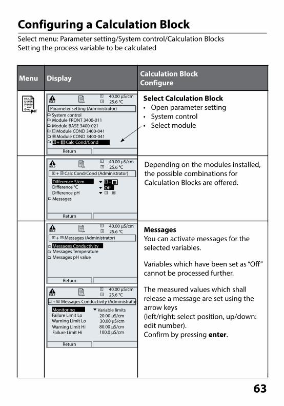
Configuring a Calculation BlockSelect menu: Parameter setting/System control/Calculation BlocksSetting the process variable to be calculated
Parameter setting (Administrator)
Return
25.6 °C40.00 µS/cm
Module FRONT 3400-011
Module COND 3400-041Module COND 3400-041
Module BASE 3400-021
System control
Calc Cond/Cond+
Menu Display Calculation Block Configure
Select Calculation Block• Open parameter setting• System control• Select module
Depending on the modules installed, the possible combinations for Calculation Blocks are offered.
MessagesYou can activate messages for the selected variables.
Variables which have been set as “Off” cannot be processed further.
The measured values which shall release a message are set using the arrow keys(left/right: select position, up/down: edit number). Confirm by pressing enter.
+ Calc Cond/Cond (Administrator)
Return
25.6 °C40.00 µS/cm
Difference °C
MessagesDifference pH
Difference S/cm
+ Messages (Administrator)
Return
25.6 °C40.00 µS/cm
Messages TemperatureMessages pH value
Messages Conductivity
+ Messages Conductivity (Administrator)
Return
25.6 °C40.00 µS/cm
Failure Limit Lo
Warning Limit HiWarning Limit Lo
Monitoring Variable limits
Failure Limit Hi
–Off
80.00 µS/cm100.0 µS/cm
30.00 µS/cm20.00 µS/cm

64
Menu Display Logbook, Factory setting
Logbook, Factory SettingParameter setting/System control/LogbookNote: HOLD mode
Logbook Select which messages are to be logged in the logbook. The last 50 events are recorded with date and time. This permits quality management documentation to ISO 9000 et seq.
The logbook can be called from the diagnostics menu (Fig.).Pressing the right softkey displays the message identifier.
Additional function SW 3400-104: Extended logbook for recording data on SmartMedia card (TAN).
Logbook (Administrator)
Return
Erase logbook
NoLog failure
Log warning
Yes
NoYes
Logbook
Return
04/13/10 09:50 Measurement active
04/12/10 17:52 Measurement active04/12/10 17:44 Parameter setting active
04/13/10 09:36 Parameter setting active
04/12/10 17:04 Measurement active04/12/10 17:40 Wrong passcode
04/12/10 16:53 Diagnostics active
Factory settingAllows resetting the parameters to their factory setting. When this menu is opened, the analyzer displays a warning (Fig.).
Factory setting (Administrator)
Return
The factory setting erasesall your set parameters!
NoYes
Logbook
Factory setting
25.6 °C0.120 mS/cm
25.6 °C0.120 mS/cm
25.6 °C0.120 mS/cm
Logbook
Return
F223 04/13/10 09:50 Diagnostics active
F224 04/12/10 17:52 Measurement activeF222 04/13/10 09:36 Parameter setting active
25.6 °C0.120 mS/cm
Measuring system

65
Parameter SettingMessages: Default Settings and Selection RangeNote: HOLD mode active
Messages
Device Limits• Device limits max. Maximum measuring range of device• Variable limits: Range limits specified
Variable limits
Device limits max.
Off, device limits max., variable limits*Off, device limits max., variable limits*Off, device limits max., variable limits*Off, device limits max., variable limits*Off, device limits max., variable limits*
* With “Variable limits” selected, the following parameters can be edited: • Failure Limit Lo • Warning Limit Lo • Warning Limit Hi • Failure Limit Hi
Messages• Conductivity• Resistivity• Concentration• Temperature• Salinity
Parameter Default Selection / Range
Limits maxOffOffOffOff
0.000 µS/cm
1999 mS/cm

66
Messages
Setting the Message ParametersMessagesNote: HOLD mode active
Menu Display
MessagesAll parameters determined by the measuring module can generate messages.• Device limits max:Messages are generated when the process variable (e.g. conductivity) is outside the measurement range. The “Failure” icon is displayed, the NAMUR failure contact is activated (BASE module, factory setting: contact K4, N/C contact). The current outputs can signal a 22 mA message (user defined).• Variable limits:For the “failure” and “warning” messages you can define upper and lower limits for message generation.
• Message icons:
Messages (Administrator)20.1 °C
Return
0.220 mS/cm
Messages Conductivity (Administrator)20.1 °C
Abort
Monitoring
0.220 mS/cm
Variable limits
OK
Device limits max.Off
Messages Temperature
Messages ResistivityMessage Conductivity
Messages Salinity
Messages Concentration
Messages (Administrator)20.1 °C0.220 mS/cm
Warning Limit Hi
MonitoringFailure Limit Lo
Failure Limit Hi
Warning Limit Lo+1999 mS/cm
Variable limits
+1999 mS/cm
-0.000 μS/cm-0.000 μS/cm
Abort OK
Message list 22.3 °C
Fail Meas. processing
0.220 mS/cm
Fail Temperature range
Abort
Diagnostics menuWhen the “Maintenance” or “Failure” icons are flashing in the display, you should open the Diagnostics menu. The messages are displayed in the “Message list”.
Failure (Failure limit HiHi/LoLo)
Maintenance (Warning limit Hi/Lo)
67
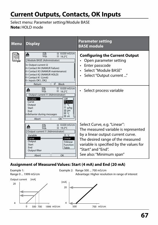
Select Curve, e.g. “Linear”: The measured variable is represented by a linear output current curve. The desired range of the measured variable is specified by the values for “Start” and “End”.See also: “Minimum span”
Current Outputs, Contacts, OK InputsSelect menu: Parameter setting/Module BASENote: HOLD mode
Menu Display Parameter setting BASE module
• Select process variable
Output current
mS/cm
20
419990
Assignment of Measured Values: Start (4 mA) and End (20 mA)
mS/cm
20
4700500
[mA]
Example 1: Range 0 ... 1999 mS/cm
Example 2: Range 500 ... 700 mS/cm Advantage: Higher resolution in range of interest
[mA]
Configuring the Current Output• Open parameter setting• Enter passcode• Select "Module BASE"• Select “Output current ...”
Module BASE (Administrator)19.2°C
Return
Contact K2 (NAMUR HOLD)
Contact K4 (NAMUR Failure)Contact K3 (NAMUR maintenance)
0.020 mS/cm
Output current I2
Contact K1 (Limit)Inputs OK1, OK2
Block
Output current I1 (Administrator)
OK
Variable
Output
Abort
Curve Linear°C
TrilinearFunctionTable
Output current I1 (Administrator)
OK
CurveOutput
Behavior during messages
Start
Abort
Variable
°Cg/kgpH°CrH
OffS/cm
EndStart
End
Output filter
500 700
19.2°C0.020 mS/cm
19.2°C0.020 mS/cm
68
[%]
100
Start End
0
Output currentY
XProcess variable
[%]
100
Start End
0
Output currentY
XProcess variable
2nd vertex Y
1st vertex Y
2nd vertex X
1st vertex X
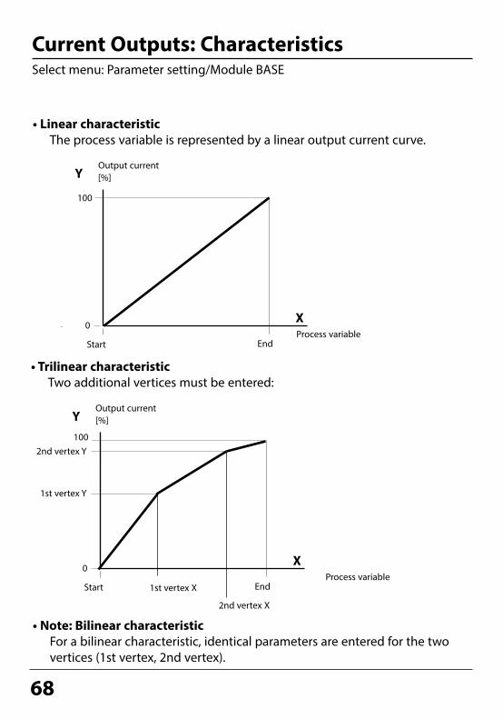
• Linear characteristic The process variable is represented by a linear output current curve.
• Note: Bilinear characteristic For a bilinear characteristic, identical parameters are entered for the two
vertices (1st vertex, 2nd vertex).
• Trilinear characteristic Two additional vertices must be entered:
Current Outputs: CharacteristicsSelect menu: Parameter setting/Module BASE

69
Output current (4 to 20 mA) = 16 mA + 4 mA
[%]
Entry for “50 % point”:e.g.: 10 % of measured value
End
0
Output currentY
XProcess variable
• Function characteristic Nonlinear output current characteristic: allows measurements over several
decades, e.g. measuring very low values with a high resolution and high values with a low resolution. Required: Entering a value for 50 % output current.
100
50
Equation
(1+K)x
1+KxE + S - 2 * X50%
X50% - SK =
M - S
E - Sx =
S: Start value at 4 mAX50%: 50% value at 12 mA (output current range 4 to 20 mA)E: End value at 20 mAM: Measured value
Logarithmic output curve over one decade: S: 10 % of maximum valueX50%: 31.6 % of maximum valueE: Maximum value
Logarithmic output curve over two decades: S: 1 % of maximum valueX50%: 10 % of maximum valueE: Maximum value

70
Output FilterTime interval
Time averaging filterTo smoothen the current output, a low-pass filter with adjustable time interval can be switched on. When there is a jump at the input (100 %), the output level is at 63 % after the time interval has been reached.The time interval can be set from 0 to 120 sec. If the time interval is set to 0 sec, the current output follows the input.
Note:The filter only acts on the current output and the current value of the second-ary display, not on the measurement display, the limit values or the controller!
Time interval 0 ... 120 sec
Process variable 0 (4) - 20 mA

71
NAMUR Signals: Current OutputsBehavior during messages: HOLD, 22mA signal
Behavior during messages
Output current[mA] “fix (22 mA)”
HOLD
22
4
“Last usable value”
HOLD
Depending on the configuration (“Messages”) the current outputs switch to:• Currently measured value• Last measured value (HOLD function)• Fixed value (22 mA)In the case of a fault a 22 mA signal can be generated for the selected process variable (1st primary value).
HOLD
"Current meas."
Behavior during messages
OK
19.0°C83.1 % Air
22mA message
Abort
HOLD
Fixed 22 mA
Current meas.Last usable value
Message when the current range is exceededAs delivered, the “Maintenance request” (Warn) message is generated when the current range is exceeded (< 3.8 mA or > 20.5 mA).This setting can be changed in the Parameter setting menu of the respective measuring module at “Messages”.
To generate a “Failure” message, the limit value monitoring must be set to “Variable limits”:Parameter setting - <measuring module> - Messages - Variable limits - Failure limit ...
Enter the same values for the failure limits as for the current output:Parameter setting - Module BASE - Output current - Variable Start / End.
Current outputs: Behavior during messages

72
NAMUR Signals: Relay ContactsFailure, maintenance request, HOLD (function check)
Failure is active when a value has exceeded (or fallen below, resp.) a preset ”Failure Limit Hi” or ”Failure Limit Lo”, when the measured value is out of range, or in the event of other failure messages. That means that the equipment no longer operates properly or that process parameters have reached a critical value. Failure is disabled during "HOLD" (Function check).
Maintenance request is activewhen a value has exceeded (or fallen below, resp.) a preset "Warning Limit Hi" or "Warning Limit Lo", or when other warning messages have been activated. That means that the equipment is still operating properly but should be ser-viced, or that process parameters have reached a value requiring intervention.Warning is disabled during "HOLD" (function check).
HOLD is active: • during calibration• during maintenance (current source, meas. point maintenance)• during parameter setting at the Operator level and the Administrator level• during an automatic rinsing cycle
As delivered, the floating relay outputs of the BASE module are assigned to the NAMUR signals:Failure Contact K4, normally closed
(signaling current failure)Maintenance request Contact K3, normally open contactHOLD Contact K2, normally open contact
NAMUR signals: Factory setting of contacts• Select parameter setting• Administrator level• Select “Module BASE” (Fig.) You can define a delay time for “Maintenance request”
and “Failure”, resp. If an alarm message is released, the contact will only be activated after expiry of this delay time.
Module BASE (Administrator)Output current I1
Return Block
7.00 pH
Contact K4Output current I2
Contact K3
19.0°C
(NAMUR failure)
Contact K2Contact K1
(NAMUR maintenance)(NAMUR HOLD)(Limit)

73
Relay Contacts: Protective Wiring
1
23
1 2
3
Typical AC applicationswith inductive load
1 Load2 RC combination, e.g. RIFA PMR 209 Typical RC combinations
e.g. capacitor 0.1 µF resistor 100 ohms / 1 W
3 Contact
Caution!Make sure that the maximum ratings of the relay contacts are not exceeded even during switching!
Protective wiring of relay contactsRelay contacts are subject to electrical erosion. Especially with inductive and capacitive loads, the service life of the contacts will be reduced. For suppres-sion of sparks and arcing, components such as RC combinations, nonlinear resistors, series resistors and diodes should be used.
Information concerning relay contactsAs delivered, the relay contacts are suitable for low signal currents (down to approx. 1 mA). If currents above approx. 100 mA are switched, the gold plating is destroyed during the switching process. After that, the contacts will not reliably switch low currents.

74
Relay ContactsParameter setting/Module BASE/Relay contacts
The BASE module provides 4 relay contacts (max. AC/DC rating 30 V / 3 A each).Contact K4 is provided for failure message. The switching behavior (normally open or normally closed), as well as a switch-on or switch-off delay can be defined.
Default settings of the user-definable relay contacts of the BASE module:K3: NAMUR maintenance requestK2: NAMUR HOLD (function check)K1: Limit value
K1-K3 are user definable (“Usage”):• NAMUR maintenance• NAMUR HOLD• Limit value• Rinse contact• Parameter set B active• USP output (COND module only)• KI rec. active• Sensoface• Alarm control
Menu Display Setting the relay contacts
Relay Contacts, Usage• Open parameter setting• Enter passcode• Select “Module BASE”• Select “Contact ...”• “Usage” (Fig.)
Module BASE
K1
K2
K3
Contact K1 (Administrator)19.2°C
Return
Hysteresis
VariableLimit value
7.00pH
Usage
Effective directionContact type
Limit value
NAMUR maintenanceNAMUR HOLD
Rinse contactParameter set B activeUSP output
Contact assignment: See terminal plate of BASE module
Relay contacts

75
Module BASE (Administrator)Output current I1
Return Block
7.00 pH
Contact K4Output current I2
Contact K3
19.0°C
(NAMUR Failure)
Contact K2Contact K1
(NAMUR maintenance)( Sensoface)( Sensoface)
Relay Contacts: Sensoface MessagesParameter setting/Module BASE/Relay contacts/Usage/Sensoface
Set contact parameters• (e.g. "N/O")• Set ON / OFF delay.
Menu Display Parameter setting (Sensoface)
Relay contacts, usage• Open parameter setting• Enter passcode• Select “Module BASE”• Select contact e.g. K1)• Assign Sensoface message of
desired measuring module to selected relay contact
Contact K1 (Administrator)19.2°C
Return
Hysteresis
VariableLimit value
7.00 pH
Usage
Effective directionContact type
Limit value
NAMUR maintenanceNAMUR HOLD
SensofaceParameter set B activeUSP output
Contact K1 (Administrator)19.2°C
Return
OFF delayON delay
7.00pH
UsageContact type
0010 s
SensofaceN/O
0010 s
Assign Sensoface messages to relay contactsWhen more than one measuring module is used, the Sensoface mes-sages of the modules can be assigned to different contacts.
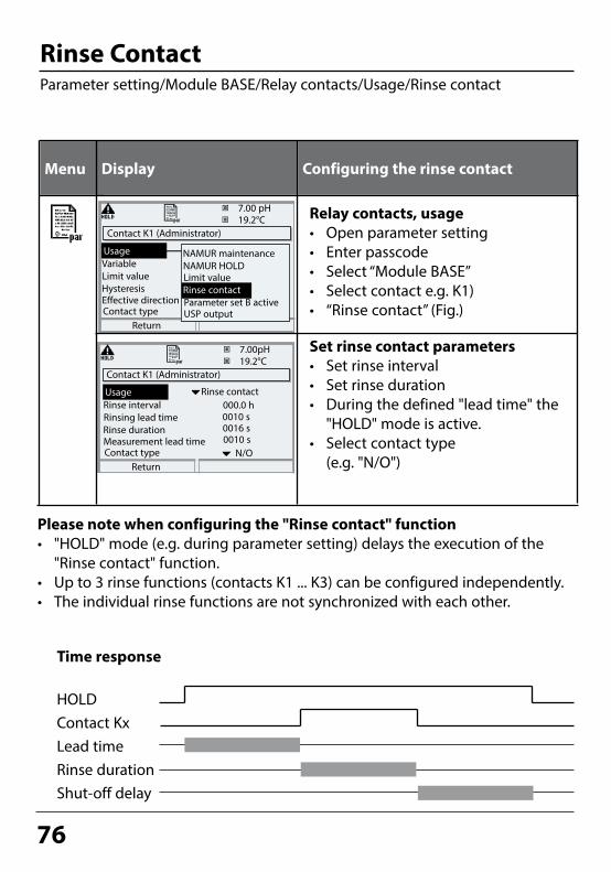
76
Set rinse contact parameters• Set rinse interval• Set rinse duration• During the defined "lead time" the
"HOLD" mode is active.• Select contact type
(e.g. "N/O")
Rinse ContactParameter setting/Module BASE/Relay contacts/Usage/Rinse contact
Menu Display Configuring the rinse contact
Relay contacts, usage• Open parameter setting• Enter passcode• Select “Module BASE”• Select contact e.g. K1)• “Rinse contact” (Fig.)
Contact K1 (Administrator)19.2°C
Return
Hysteresis
VariableLimit value
7.00 pH
Usage
Effective directionContact type
Limit value
NAMUR maintenanceNAMUR HOLD
Rinse contactParameter set B activeUSP output
Rinse contact
Contact K1 (Administrator)19.2°C
Return
Rinse duration
Rinse intervalRinsing lead time
7.00pH
Usage
Measurement lead timeContact type
0010 s
Rinse contact000.0 h
0010 sN/O
0016 s
Please note when configuring the "Rinse contact" function• "HOLD" mode (e.g. during parameter setting) delays the execution of the
"Rinse contact" function.• Up to 3 rinse functions (contacts K1 ... K3) can be configured independently.• The individual rinse functions are not synchronized with each other.
Time response
HOLDContact KxLead timeRinse durationShut-off delay

77
Limit Value, Hysteresis, Contact TypeParameter setting/Module BASE/Relay contacts/Usage
Menu Usage as limit value
Relay output: Limit value• Open parameter setting• Enter passcode• Select “Module BASE”• Select “Contact ...”• “Usage: Limit” (Fig.)
Limit valueEffective direction min
Hysteresis +
Limit value
Contact
0
1
Signal
Limit valueEffective direction max
Hysteresis -
Signal
Limit value
Contact
0
1
Contact typeSpecifies whether the active contact is closed (N/O) or open (N/C).
Contact K1 (Administrator)19.2°C
Return
Hysteresis
VariableLimit value
7.00 pH
Usage
Effective directionContact type
Limit value
NAMUR maintenanceNAMUR HOLD
Rinse contactParameter set B activeUSP output
HysteresisTolerance band around the limit value, within which the contact is not actuated. Serves to obtain appropriate switching behavior at the outputand suppress slight fluctuations of the measured variable (Fig.)
Icons in the Measurement DisplayMeasured value falls below limit:Measured value exceeds limit:
Limit value
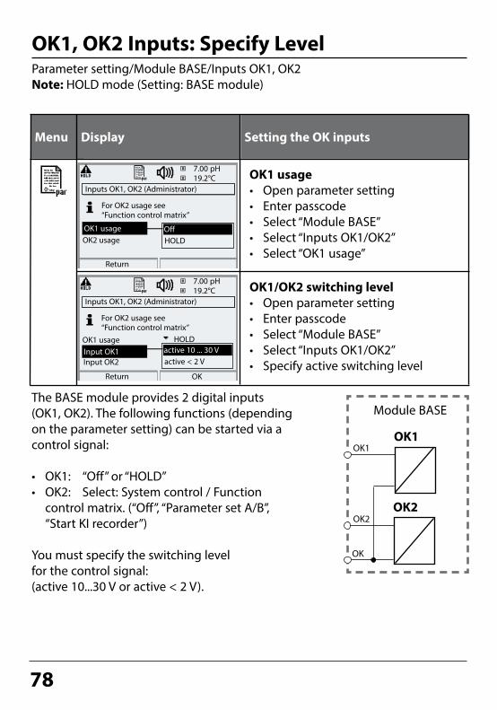
78
OK1, OK2 Inputs: Specify LevelParameter setting/Module BASE/Inputs OK1, OK2Note: HOLD mode (Setting: BASE module)
Menu Display Setting the OK inputs
OK1 usage• Open parameter setting• Enter passcode• Select “Module BASE”• Select “Inputs OK1/OK2”• Select “OK1 usage”
OK1/OK2 switching level• Open parameter setting• Enter passcode• Select “Module BASE”• Select “Inputs OK1/OK2”• Specify active switching level
The BASE module provides 2 digital inputs (OK1, OK2). The following functions (depending on the parameter setting) can be started via a control signal:
• OK1: “Off” or “HOLD”• OK2: Select: System control / Function
control matrix. (“Off”, “Parameter set A/B”, “Start KI recorder”)
You must specify the switching level for the control signal: (active 10...30 V or active < 2 V).
Module BASE
OK1
OK2
OK1
OK2
OK
Inputs OK1, OK2 (Administrator)19.2°C
Return
OK2 usage
7.00 pH
OK1 usage OffHOLD
For OK2 usage see“Function control matrix”
Inputs OK1, OK2 (Administrator)19.2°C
Return
OK1 usage
7.00 pH
Input OK1 active 10 ... 30 Vactive < 2 V
For OK2 usage see“Function control matrix”
HOLD
Input OK2
OK

79
Switching Parameter Sets via OK2Parameter setting / System control / Function control matrixNote: HOLD mode (Setting: BASE module)
Parameter Sets2 complete parameter sets (A, B) can be stored in the analyzer. You can switch between the parameter sets using the OK2 input. The currently activated set can be signaled by a relay contact. An icon in the measurement display shows which parameter set is active: or
Menu Display Parameter sets
Signaling Active Parameter Set via Relay Contact• Open parameter setting• BASE module• Select contact• Usage: “Parameter set ...”.
Select Parameter Set (A, B) via OK2 Input• Open parameter setting• System control• Function control matrix• Select “OK2”• Connect “Parameter set A/B”
Contact K3 (Administrator)
Abort
24.8°C
Contact type
OK
NAMUR maintenance!Usage
ON delayNAMUR HOLDLimit valueRinse contactParameter set B activeUSP output
83.1 % Air
OFF delay
NoteThe selection has no effect when working on SmartMedia card with SW 3400-102.
24.8°C
Left softkey
83.1 % Air
Return Connect
Function control matrix (Administrator)
Input OK2
Right softkeyProfibus DO 2
ParSet KI rec. Fav Unical– –
––––

80
Maintenance
MaintenanceSensor monitor, Temp probe adjustmentNote: HOLD mode active
Menu Display Maintenance
Open MaintenanceFrom the measuring mode:Press menu key to select menu.Select maintenance using arrow keys, confirm by pressing enter.Passcode 2958 (The passcode can be edited by the administrator.)Then select Module COND.
Temp probe adjustmentThis function allows you to compen-sated for the individual temperature probe tolerance and the influence of the lead resistances to increase accuracy of temperature measure-ment. Adjustment may only be carried out after the process temperature has been precisely measured using a calibrated reference thermometer! The measurement error of the refer-ence thermometer should be less than 0.1 °C. Adjustment without precise measurement might result in consider-able deviations of the measured value display!
Sensor monitorDuring maintenance, the sensor mon-itor allows validation of the sensor by immersing it in a known solution, for example, and checking the values measured.
Menu selection
Return to meas
25.6 °C
Select: [enter]
Lingua
Return
25.6 °C0.225 mS/cm
0.225 mS/cm
Adjust temp probeProbe tolerance and lead adjustment
25.6 °C0.225 mS/cm
Enter measured process temp
Installation adjustment
Abort OK
OffProcess temperature
On+025.6°C
Sensor monitor
Resistance (c=1)Conductance (c=1)RTD
9,987 MΩ0.225 mS1100 Ω
Temperature 25.6 °C
Sensor monitorTemp probe adjustment

81
Diagnostics
Menu Display Diagnostics functions
Opening the Diagnostics MenuFrom the measuring mode:Press menu key to select menu.Select diagnostics using arrow keys,confirm by pressing enter.
The “Diagnostics” menu gives an overview of all functions available. Functions which have been set as “Favorite” can be directly accessed from the measuring mode.
Diagnostics FunctionsGeneral status information of the measuring system Select menu: Diagnostics
Point of Meas DescriptionAllows entering a tag number and a note. Select position: left/right arrow key, select character: up/down arrow key. Confirm the entry by pressing enter.
LogbookShows the last 50 events with date and time, e.g. calibrations, warning and failure messages, power failure etc. This permits quality management documentation to ISO 9000. Extended logbook:SmartMedia card (SW 3400-104)
Menu selection
Return to meas
0.002 mS/cm23.7 °C
Select: [enter]
Lingua
Diagnostics
Return
23.7 °C
Set favorite
0.003 mS/cm
LogbookMessage list
Device descriptionModule FRONT
Return
23.7 °C0.003 mS/cm
Module BASE
Logbook23.7 °C0.003 mS/cm
Point of meas description
Point of meas descriptionLogbook
Return
U229 04/13/10 09:50 • Warn Sensor dismou
F224 04/12/10 17:52 Measurement activeF222 04/12/10 17:44 Parameter setting active
F222 04/13/10 09:36 Parameter setting active
U229 04/11/10 06:51 Warn Sensor dismouU229 04/11/10 06:50 • Warn Sensor dismou
Releasing module:• Message activated
Message deactivated
Point of meas description
Note:Tank_2Measurement point:04/03/2007 smith

82
Menu Display Diagnostics functions
Device DescriptionSelect module using arrow keys:Provides information about all modules installed: Function, serial number, hardware and software version and device options.
FRONT ModuleThe module contains the display and keypad control. Test possibilities:• Module diagnostics• Display test• Keypad test
BASE ModuleThe module generates the standard output signals. Test possibilities:• Module diagnostics• Input/output status
Example:Module BASE, input/output status.
Device description
Return
22.7 °C1.225 mS/cm
Input for 2/4-electr. sensors and °CModule COND 3400-041
Hardware: 1, Software: 2.0Serial number 0002283
BASEModule FRONT
Module FRONT
Return
22.7 °C1.225 mS/cm
Display testKeypad test
Module diagnostics
Module BASE
Return
22.7 °C1.225 mS/cm
Input/output status
Set favorite
Module diagnostics
Input/output status
Return
22.7 °C1.225 mS/cm
Current load I1
K1Current load I2 okContact
Input OK1
ok
Input OK2
K3InactiveInactive
K2K4
Diagnostics FunctionsDevice description, FRONT module, BASE module
Device description
Set favorite

83
Menu Display Module diagnostics / Sensor monitor / ServiceScope
Opening the diagnostics menuFrom the measuring mode:Press menu key to select menu.Select diagnostics using arrow keys, confirm by pressing enter.Then select "Module COND".
The Diagnostics menu gives an over-view of all diagnostics functions avail-able. Messages set as “Favorite” can be called up directly from the measuring mode using a softkey. To configure: Parameter setting / System control / Function control matrix.
Module DiagnosticsInternal function test (without Fig.).
Sensor MonitorShows the values currently measured by the sensor. Important function for diagnostics and validation! (cf Maintenance)
Cal RecordData of last calibration, suitable for documentation to ISO 9000 and GLP
Menu selection
Return to meas
22.3 °C
Select: [enter]
Lingua
Module COND 3400-04122.3 °C
Return
Cal recordSensor monitor
1.225 mS/cm
1.225 mS/cm
Set favorite
Module diagnostics
Sensor monitor22.3 °C1.225 mS/cm
Module DiagnosticsModule diagnostics, sensor monitor, cal record
Module diagnostics, Sensor monitor, Cal record
Return
Resistance (c=1)Conductance (c=1)Temperature
0.0 Ohm0.000 µS25.6 °C
Cal record
Return
25.6°C0.245 mS/cm
Active adjustmentSensor modelSerial number
06/09/10 14:06
Cal modeCell constant
0077123Product cal0.029
SE604

84
Setting Diagnostics Messages as FavoriteSelect menu: Parameter setting/System control/Function control matrix
Example:“Favorites” to be selected with “Right softkey”
To select a softkey function:Select desired function using arrow keys,press “Connect” softkey and confirm with enter.
To deselect a function:Press “Disconnect” softkey,confirm with enter.
1
2
25.6 °C
Input OK2
0245 mS/cm
Return Connect
Function control matrix (Administrator)
Left softkeyRight softkeyProfibus DO 2
ParSet KI rec. Fav Unical– –
––––
FavoritesSelected Diagnostics functions can be called directly from the measuring mode using a softkey. The table on the next page explains how to select favorites.
Secondary displays (1)Here, additional values are displayed in the measuring mode according to the factory setting. When the respective softkey (2) is pressed, the process variables measured by the modules plus date or time are displayed.In addition, you can use the softkeys (2) to control functions. To assign a function to a softkey, select
Parameter setting/System control/ Function control matrix
Function which can be controlled by softkeys:• Parameter set selection• KI recorder Start/Stop• Favorites• Unical (fully automated probe controller)
Setting diagnostics mes-sages as favorite

85
Set/delete favorite:“Set favorite” allows activation of the selected diagnostic function directly from the measuring mode via softkey.The menu line is marked with a heart icon.
Pressing the meas key returns to measurement. When the softkey has been assigned to “Favorites”, “Favorites menu” is read in the secondary display (see “Function control matrix”).
Notice:When one of the softkeys has been assigned to the “Favorites menu” function, diagnostic functions which have been set as “Favorite” can be directly called from the measuring mode.
Menu Display Select favorites
Favorites menuDiagnostics functions can be called directly from the measuring mode using a softkey. The “Favorites” are selected in the Diagnostics menu.
Select favoritesPress menu key to select menu.Select diagnostics using arrow keys, confirm with enter. Then select module and confirm with enter.
09.03.10 Favorites menu
°C09.03.10 Favorites menu
Menu selection
Return to meas
0245 mS/cm25.6 °C
Select: [enter]
Lingua
Return
25.6 °C
Set favorite
0245 mS/cm
Sensor monitorCal recordUSP function
Module diagnosticsModule COND 3400-041
°C
0.245 mS/cm
0.245 mS/cm

86
Menu Display Diagnostics functions
Opening the diagnostics menuFrom the measuring mode:Press menu key to select menu.Select diagnostics using arrow keys,confirm by pressing enter.
The “Diagnostics” menu gives an overview of all functions available. Functions which have been set as “Favorite” can be directly accessed from the measuring mode.
Diagnostics FunctionsGeneral status information of the measuring systemSelect menu: Diagnostics - Message list
Message list Shows the currently activated warning or failure messages in plain text.
Menu selection
Return to meas
120 mS/cm25.6°C
Select: [enter]
Lingua
Diagnostics
Return
23.7 °C
Set favorite
120 mS/cm
Logbook
Message list
Device descriptionModule FRONT
Message list
Return
25.6°C120 mS/cm
Warn
Module BASE
8 messg.
Message list
Point of meas description
Warn Temp alarm HI
Saturation %Air Alarm HIFail Wrong ISM sensorWarn Tolerance band
Warn Zero range
D062P018
D013P210
P030
Sensocheck
P092
Number of messagesWhen there are more than 7 messages, a verti-cal scrollbar appears. Scroll with the up/down arrow keys.
Module identifierSpecifies the module that has generated the message.
Message identifierSee message list for description.

87
Messages
COND 3400(X)-041 Module
No. COND messages Message type
C008 Meas. processing (factory settings) FAIL
C009 Module failure (Firmware Flash check sum) FAIL
C010 Conductivity range FAIL
C011 Conductivity Alarm LO_LO FAIL
C012 Conductivity Alarm LO WARN
C013 Conductivity Alarm HI WARN
C014 Conductivity Alarm HI_HI FAIL
C015 Temperature range FAIL
C016 Temperature Alarm LO_LO FAIL
C017 Temperature Alarm LO WARN
C018 Temperature Alarm HI WARN
C019 Temperature Alarm HI_HI FAIL
C020 Resistivity range FAIL
C021 Resistivity Alarm LO_LO FAIL
C022 Resistivity Alarm LO WARN
C023 Resistivity Alarm HI WARN
C024 Resistivity Alarm HI_HI FAIL
C025 Concentration range FAIL
C026 Concentration Alarm LO_LO FAIL
C027 Concentration Alarm LO WARN
C028 Concentration Alarm HI WARN
C029 Concentration Alarm HI_HI FAIL
C035 Cell constant range WARN
C040 Salinity range FAIL
C041 Salinity Alarm LO_LO FAIL
C042 Salinity Alarm LO WARN
C043 Salinity Alarm HI WARN

88
Messages
No. COND messages Message type
C044 Salinity Alarm HI_HI FAIL
C045 Conductance range FAIL
C050 man. Temperature range FAIL
C060 SAD SENSOFACE: Polarization User-defined
C061 SAD SENSOFACE: Cable User-defined
C090 USP limit value User-defined
C120 Wrong ISM sensor FAIL
C121 ISM sensor FAIL
C122 ISM sensor memory WARN
C123 New sensor, adjustment required WARN
C130 SIP cycle counted Text
C131 CIP cycle counted Text
C200 Reference temperature WARN
C201 TC correction WARN
C202 TC range WARN
C203 TC range FAIL
C204 Cal: Sensor unstable Text
C205 Cal: Sensor failure Text
C254 Module reset Text
No. Calculation Block COND/COND messages Message type
E010 Conductivity-Diff Range FAIL
E011 Conductivity-Diff Alarm LO_LO FAIL
E012 Conductivity-Diff Alarm LO WARN
E013 Conductivity-Diff Alarm HI WARN
E014 Conductivity-Diff Alarm HI_HI FAIL
E015 Temperature-Diff Range FAIL
E016 Temperature-Diff Alarm LO_LO FAIL
E017 Temperature-Diff Alarm LO WARN
E018 Temperature-Diff Alarm HI WARN
E019 Temperature-Diff Alarm HI_HI FAIL

89
Messages
No. Calculation Block COND/COND messages Message type
E020 Resistivity-Diff range FAIL
E021 Resistivity-Diff Alarm LO_LO FAIL
E022 Resistivity-Diff Alarm LO WARN
E023 Resistivity-Diff Alarm HI WARN
E024 Resistivity-Diff Alarm HI_HI FAIL
E030 RATIO range FAIL
E031 RATIO Alarm LO_LO FAIL
E032 RATIO Alarm LO WARN
E033 RATIO Alarm HI WARN
E034 RATIO Alarm HI_HI FAIL
E035 PASSAGE range FAIL
E036 PASSAGE Alarm LO_LO FAIL
E037 PASSAGE Alarm LO WARN
E038 PASSAGE Alarm HI WARN
E039 PASSAGE Alarm HI_HI FAIL
E045 REJECTION range FAIL
E046 REJECTION Alarm LO_LO FAIL
E047 REJECTION Alarm LO WARN
E048 REJECTION Alarm HI WARN
E049 REJECTION Alarm HI_HI FAIL
E050 DEVIATION range FAIL
E051 DEVIATION Alarm LO_LO FAIL
E052 DEVIATION Alarm LO WARN
E053 DEVIATION Alarm HI WARN
E054 DEVIATION Alarm HI_HI FAIL
E055 c(NaOH) range FAIL
E060 pH value range FAIL
E061 pH value Alarm LO_LO FAIL
E062 pH value Alarm LO WARN
E063 pH value Alarm HI WARN
E064 pH value Alarm HI_HI FAIL
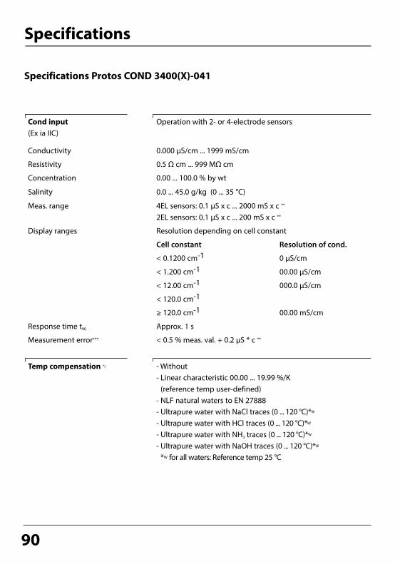
90
Specifications
Specifications Protos COND 3400(X)-041
Cond input(Ex ia IIC)
Operation with 2- or 4-electrode sensors
Conductivity 0.000 µS/cm ... 1999 mS/cm
Resistivity 0.5 Ω cm ... 999 MΩ cm
Concentration 0.00 ... 100.0 % by wt
Salinity 0.0 ... 45.0 g/kg (0 ... 35 °C)
Meas. range 4EL sensors: 0.1 µS x c ... 2000 mS x c **
2EL sensors: 0.1 µS x c ... 200 mS x c **
Display ranges Resolution depending on cell constant
Cell constant Resolution of cond.
< 0.1200 cm-1 0 µS/cm
< 1.200 cm-1 00.00 µS/cm
< 12.00 cm-1 000.0 µS/cm
< 120.0 cm-1
≥ 120.0 cm-1 00.00 mS/cm
Response time t90 Approx. 1 s
Measurement error*** < 0.5 % meas. val. + 0.2 µS * c **
Temp compensation *) - Without- Linear characteristic 00.00 ... 19.99 %/K
(reference temp user-defined)- NLF natural waters to EN 27888- Ultrapure water with NaCl traces (0 ... 120 °C)*W
- Ultrapure water with HCl traces (0 ... 120 °C)*W
- Ultrapure water with NH3 traces (0 ... 120 °C)*W
- Ultrapure water with NaOH traces (0 ... 120 °C)*W
*W for all waters: Reference temp 25 °C

91
Specifications
Temperature input
(Ex ia IIC)
Temperature probe * Pt100 / Pt1000 / NTC 30 kΩ / Ni 1003-wire connection, adjustable
Measurement range (MR) Pt100 / Pt1000: -50 ... +250 °CNTC 30 kΩ: -10 ... +150 °CNi 100: -50 ... +180 °C
Resolution 0.1 °C
Measurement error*** 0.2 % meas.val. + 0.5 K
Concentration determination *
For the substances:
(add. function SW 3400-009) HNO3 0 ... 28 % by wt –20 ... +50 °C
35 ... 96 % by wt –20 ... +50 °C
HCl 0 ... 18 % by wt –20 ... +50 °C
22 ... 39 % by wt –20 ... +50 °C
H2SO4 **** 0 ... 30 % by wt -17.8 ... +110 °C
32 ... 84 % by wt -17.8 ... +115.6 °C
92 ... 99 % by wt -17.8 ... +115.6 °C
NaOH ***** 0 ... 14 % by wt 0 ... +100 °C
18 ... 50 % by wt 0 ... +100 °C
NaCl 0 ... 28 % by wt 0 ... +100 °C
User-defined concentration table (5x5 values)
Sensor monitoring * Sensocheck;Polarization and cable capacitance
Sensoface Provides information on the sensor condition
Sensor standardization * Operating modes
- Automatic calibration with KCl or NaCl solution
- Manual: entry of conductivity
- Product calibration / adjustment to container

92
Specifications
- Entry of cell constant with simultaneous display of conductivity and temperature
Permissible cell constant 0.0050 ... 199.99 cm-1
Calibration record Recording of: Cell constant, calibration method, with date and time
Output curves * Linear
Trilinear
Function (logarithmic)
As desired via table
USP function Water monitoring in the pharmaceutical industry (USP)with possibility to enter a limit value (%)Output via relay contact (K1 ... K3, BASE) possibleThe USP value is available as USP% process variable (selectable for display, current output, limit value, measurement recorder).
* User-defined** c = 0.0050 ... 199.99 cm–1*** To IEC Part 1, at nominal operating conditions, ± 1 count, plus sensor error**** Range limits based on 27 °C***** Range limits based on 25 °C
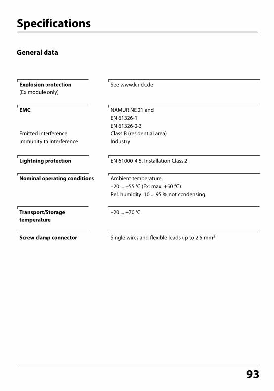
93
Specifications
General data
Explosion protection(Ex module only)
See www.knick.de
EMC
Emitted interferenceImmunity to interference
NAMUR NE 21 andEN 61326-1EN 61326-2-3Class B (residential area)Industry
Lightning protection EN 61000-4-5, Installation Class 2
Nominal operating conditions Ambient temperature:–20 ... +55 °C (Ex: max. +50 °C)Rel. humidity: 10 ... 95 % not condensing
Transport/Storage temperature
–20 ... +70 °C
Screw clamp connector Single wires and flexible leads up to 2.5 mm2

94

95
AppendixMinimum Spans for Current Outputs
The COND 3400(X)-041 module is a measuring module. It does not provide current outputs. Current outputs are provided by the BASE module (basic device) or by communication modules (e.g. OUT module). The corresponding parameters must be set there.
The minimum current span shall prevent that the resolution limit of the measurement technology (± 1 count) is seen in the current.
COND 3400(X)-041 moduleS/cm 20 %, min. 0.2 µS/cm% by wt 1.00°C 10.0g/kg 1.00Ohm*cm 20 %, min. 100.0 ohms*cm°F 10.0
Calculation Block COND/COND
Diff S/cm 20 %, min. 0.2 µS/cmDiff °C 10.0Diff Ohm*cm 20 %, min. 100.0 ohms*cmRATIO 0.10PASSAGE 10.0REJECTION 10.0DEVIATION 10.0pH 1.00

96
Parameter settingActivated from measuring mode: Press menu key to select menu.Select parameter setting using arrow keys, confirm with enter.Administrator levelAccess to all functions, also passcode setting. Releasing or blocking functions for access from the Operator level.Operator levelAccess to all functions which have been released at the Administrator level. Blocked functions are displayed in gray and cannot be edited.Viewing levelOnly display, no editing possible!
Menu selection
Return to meas
Select: [enter]
Lingua
Parameter setting
Return
Viewing level
Administrator level (All Data) adm(Operation Data) opl(All Data) view
Operator level
System control
Parameter sets• Load• Save
Overview of Parameter Setting
2 parameter sets (A,B) are available in the analyzer. The currently active parameter set is read on the display.Parameter sets contain all settings except:Sensor type, Options, System control settingsUp to 5 parameter sets (1, 2, 3, 4, 5) are available when a SmartMedia card (Option) is used.
Memory card (Option)• Record logbook• Register recorder• Decimal separator• Card full• Format
Menu only appears with SmartMedia Card inserted. Make sure that it is a memory card,not an update card.Commercially available SmartMedia cards must be formatted in the analyzer before they can be used as memory card.
Copy configuration The complete configuration of an analyzer can be written on a SmartMedia card. This allows transferring all device settings to other devices with identical equipment (exception: options and passcodes).
Function control matrix• Input OK2• Left softkey• Right softkey
Selecting the control element for the following functions:- Parameter set selection- KI recorder (start/stop)- Favorites menu (selected diagnostics functions)- Unical (fully automated probe controller)
Time/datePoint of meas descriptionRelease of optionsSoftware updateLogbookBuffer tableFactory settingPasscode entry
Selecting the display format, entryCan be called from the diagnostics menu.A TAN is required to release an Option.Software update from SmartMedia card (update card)Selecting events to be recordedEntering own buffer set for automatic calibrationResetting all parameters to factory settingEditing the passcodes
25.6 °C7.00 pH
25.6 °C7.00 pH
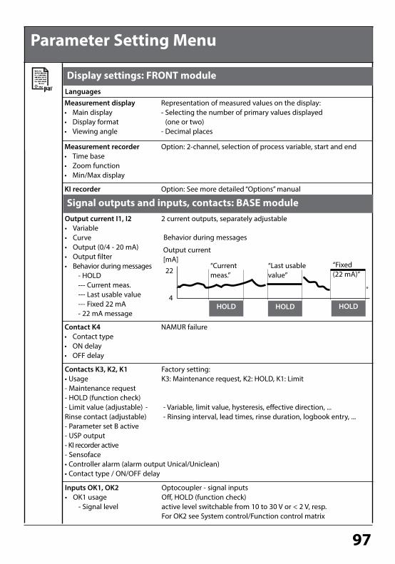
97
Display settings: FRONT module
Measurement recorder• Time base• Zoom function• Min/Max display
Parameter Setting Menu
Option: 2-channel, selection of process variable, start and end
LanguagesMeasurement display• Main display• Display format• Viewing angle
Representation of measured values on the display:- Selecting the number of primary values displayed
(one or two)- Decimal places
Output current I1, I2• Variable• Curve• Output (0/4 - 20 mA)• Output filter• Behavior during messages - HOLD --- Current meas. --- Last usable value --- Fixed 22 mA - 22 mA message
2 current outputs, separately adjustable
KI recorder Option: See more detailed “Options” manual
Signal outputs and inputs, contacts: BASE module
Contact K4• Contact type• ON delay• OFF delay
NAMUR failure
Contacts K3, K2, K1• Usage- Maintenance request- HOLD (function check) - Limit value (adjustable) - Rinse contact (adjustable)- Parameter set B active- USP output- KI recorder active- Sensoface• Controller alarm (alarm output Unical/Uniclean)• Contact type / ON/OFF delay
Factory setting:K3: Maintenance request, K2: HOLD, K1: Limit
- Variable, limit value, hysteresis, effective direction, ... - Rinsing interval, lead times, rinse duration, logbook entry, ...
Inputs OK1, OK2• OK1 usage - Signal level
Optocoupler - signal inputsOff, HOLD (function check) active level switchable from 10 to 30 V or < 2 V, resp.For OK2 see System control/Function control matrix
Output current[mA]
“Fixed (22 mA)”
HOLD
22
4
“Last usable value”
HOLD HOLD
“Current meas.”
Behavior during messages

98
COND 3400(X)-041 Module
Parameter Setting Menu
Input filterSensor data• Sensor type• Nom. cell constant• Temperature detection - Temperature probe - Measuring temp - Calibration temp• Sensocheck
Representation of measured values on the display:- Select
- Selection for Measurement / Calibration
Cal preset values• Cal solution - NaCl 0.01 mol/l - NaCl 0.1 mol/l - NaCl saturated - KCl 0.01 mol/l - KCl 0.1 mol/l - KCl 1 mol/l• Product calibration
TC process medium Select: Off, linear, EN 27888, ultrapure water
Concentration
Messages• Conductivity• Resistivity• Temperature• Salinity
USP function
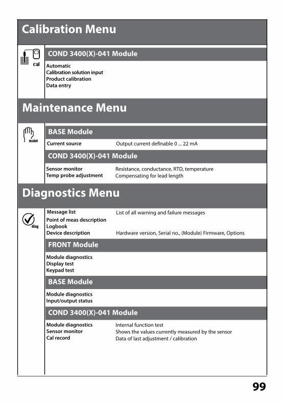
99
COND 3400(X)-041 Module
Calibration Menu
AutomaticCalibration solution inputProduct calibrationData entry
Current source Output current definable 0 ... 22 mA
Message list List of all warning and failure messages
Hardware version, Serial no., (Module) Firmware, Options
BASE Module
COND 3400(X)-041 Module
Sensor monitor Temp probe adjustment
Resistance, conductance, RTD, temperatureCompensating for lead length
FRONT Module
Module diagnosticsDisplay testKeypad test
BASE Module
Module diagnosticsInput/output status
COND 3400(X)-041 Module
Module diagnosticsSensor monitorCal record
Internal function testShows the values currently measured by the sensorData of last adjustment / calibration
Maintenance Menu
Diagnostics Menu
Point of meas descriptionLogbookDevice description

100
AAdjustment ..................................................................................................................................30Administrator level ...................................................................................................................43Application in hazardous locations ...................................................................................... 7Automatic calibration with standard calibration solution .........................................34Automatic temperature compensation ............................................................................31
BBASE module ..............................................................................................................................13Behavior during messages ....................................................................................................71
CCable glands................................................................................................................................10Calculation Blocks .....................................................................................................................61Calibrating the sensors ...........................................................................................................41Calibration ...................................................................................................................................29Cal preset values ........................................................................................................................52Cal record .....................................................................................................................................83Change passcode ......................................................................................................................25Concentration .............................................................................................................................54Concentration curves ..............................................................................................................54Concentration table .................................................................................................................57Configuration with ProgaLog 3000 ....................................................................................48Configurator menu of "ProgaLog 3000" ...........................................................................51Configure measurement display .........................................................................................26Configuring the current output ...........................................................................................67Contact assignments ...............................................................................................................14Contact type................................................................................................................................77Current outputs:Characteristics ...........................................................................................68Current outputs, minimum spans .......................................................................................95
DData entry of premeasured sensors ...................................................................................40Device description, diagnostics menu ..............................................................................82Device limits max. .....................................................................................................................66Device software ........................................................................................................................... 8Diagnostics ..................................................................................................................................81
Index

101
Diagnostics messages .............................................................................................................86Diagnostics messages as favorite........................................................................................84Disposal .......................................................................................................................................... 2Documenting parameter setting .................................................................................46, 47
EEMC ................................................................................................................................................93Explosion protection ................................................................................................................93
FFactory setting ...........................................................................................................................64Failure, signaling ........................................................................................................................72Favorites ........................................................................................................................................84FDA 21 CFR Part 11 ..................................................................................................................... 6FRONT module ...........................................................................................................................12Function check ...........................................................................................................................72
GGraphic display ..........................................................................................................................10
HHardware and software version ............................................................................................. 8HOLD ..............................................................................................................................................72Hydrochloric acid ......................................................................................................................55Hysteresis .....................................................................................................................................77
IIcons ............................................................................................................................................ 107Input filter ....................................................................................................................................52Inserting the module ...............................................................................................................15Intended use ................................................................................................................................. 6
LLED ..................................................................................................................................................10Limit value ...................................................................................................................................77Limit value, icons in the measurement display ..............................................................77Linear characteristic .................................................................................................................68Lock icon.......................................................................................................................................44
Index

102
Locking a function ....................................................................................................................44Logarithmic output curve ......................................................................................................69Logbook, diagnostics menu ..................................................................................................81Logbook, parameter setting .................................................................................................64
MMaintenance ...............................................................................................................................80Manual entry of cal solution .................................................................................................36Manual temperature compensation ..................................................................................31Menu selection ...........................................................................................................................24Menu structure ...........................................................................................................................11Message icons ............................................................................................................................66Message list .................................................................................................................................86Messages ......................................................................................................................................66Messages, response of current outputs ............................................................................71Message when the current range is exceeded ..............................................................71Modular concept ......................................................................................................................... 9Module diagnostics ..................................................................................................................83Module equipment...................................................................................................................13Modules ........................................................................................................................................12Module software ......................................................................................................................... 8
NNAMUR signals:Current outputs ..........................................................................................71NAMUR signals, relay contacts .............................................................................................72Nitric acid .....................................................................................................................................55
OOK1/OK2 inputs .........................................................................................................................78OK1/OK2 switching level ........................................................................................................78OK1 usage ....................................................................................................................................78OK2, selecting parameter set (A, B) ....................................................................................79Operating levels .........................................................................................................................43Operator level .............................................................................................................................43Output filter .................................................................................................................................70Overview ......................................................................................................................................97Overview of parameter setting ............................................................................................96
Index

103
Index
PParameter setting ......................................................................................................................43Parameter setting, documenting ........................................................................................46Parameter setting: TC process medium ............................................................................52Passcode entry ...........................................................................................................................25Passcode lost ...............................................................................................................................25pH value calculation .................................................................................................................58Point of meas description ......................................................................................................81Product calibration ...................................................................................................................38ProgaLog 3000 software .........................................................................................................48Protective wiring .......................................................................................................................73
RReduced limit ..............................................................................................................................60Relay contacts, protective wiring ........................................................................................73Relay contacts, usage ..............................................................................................................74Relay output, limit value .........................................................................................................77Release (softkey function) ......................................................................................................44Replacing the front module ..................................................................................................12Return of products under warranty ..................................................................................... 2Rinse contact ..............................................................................................................................76
SSafety information ...................................................................................................................... 7Salt solution.................................................................................................................................56Screw clamp connector ..........................................................................................................93Sealing ...........................................................................................................................................12Secondary displays ...................................................................................................................26Sensor data ..................................................................................................................................52Sensor monitor, diagnostics menu .....................................................................................83Sensor monitor, maintenance menu .................................................................................80Serial number ............................................................................................................................... 8Settings documentation .........................................................................................................46Shield .............................................................................................................................................15Short description .......................................................................................................................10Signaling active parameter set via relay contact ..........................................................79Slot for SmartMedia card........................................................................................................12

104
Index
SmartMedia card .......................................................................................................................12Sodium hydroxide solution ...................................................................................................56Softkeys .........................................................................................................................................26Software version .......................................................................................................................... 8Specifications ..............................................................................................................................90Sulfuric acid .................................................................................................................................54Switching parameter sets via OK2 ......................................................................................79
TTable of contents ......................................................................................................................... 3TC process medium ..................................................................................................................52Temperature compensation during calibration.............................................................31Temperature probe adjustment ..........................................................................................80Temp probe adjustment .........................................................................................................80Terminal compartment ...........................................................................................................13Trademarks .................................................................................................................................... 2
UUltrapure water ..........................................................................................................................53USP function ...............................................................................................................................60
VVariable limits .............................................................................................................................66Viewing level ...............................................................................................................................43
WWiring examples ........................................................................................................................16

105
Index

106

107
Icon Explanation of Icons Important for this Module
The analyzer is in measuring mode.
The analyzer is in calibration mode. HOLD mode active for the currently calibrated module
The analyzer is in maintenance mode. HOLD mode active.
The analyzer is in parameter setting mode. HOLD mode active.
The analyzer is in diagnostics mode.
HOLD. The NAMUR “HOLD” contact is active (factory setting: Module BASE, Contact K2, N/O contact). Current outputs as configured: • Current meas.: The currently measured value appears at the current output • Last usable value: The last measured value is held at the current output• Fixed 22 mA: The output current is at 22 mA
Calibration is performed
Calibration - Step 1 of product calibration has been executed. The analyzer is waiting for the sample values.
Temperature detection by manual input
In the plaintext display in front of a menu line:Access to next menu level with enter
In the plaintext display in front of a menu line when it has been blocked by the Administrator against access from the Operator level.
Designates the module slot (1, 2 or 3), allowing the clear assignment of measured-value/parameter displays in the case of identical module types.
Indicates the active parameter set . (The analyzer provides two parameter sets A and B. Up to 5 sets can be added using additional functions and SmartMedia card.)
Failure. The NAMUR “failure” contact is active (factory setting: Module BASE, Contact K4, N/C contact). To view error message, call: Diagnostics menu/Message listMaintenance. The NAMUR “maintenance request” contact is active (factory setting: Module BASE, Contact K2, N/O contact). To view error message, call: Diagnostics menu/Message list
NA
MU
R si
gnal
s
Calibration:Temperature compensation for process medium is active (Linear/Ultrapure water/Table)
TC
man
Limit indication: Lower / upper range limit exceeded
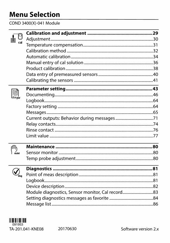
Menu SelectionCOND 3400(X)-041 Module
Calibration and adjustment ...................................................29Adjustment .....................................................................................................30Temperature compensation .....................................................................31Calibration method .....................................................................................32Automatic calibration .................................................................................34Manual entry of cal solution ....................................................................36Product calibration ......................................................................................38Data entry of premeasured sensors ......................................................40Calibrating the sensors ..............................................................................41
TA-201.041-KNE08 Software version 2.x20170630091953
Parameter setting ....................................................................43Documenting .................................................................................................46Logbook ...........................................................................................................64Factory setting ..............................................................................................64Messages .........................................................................................................65Current outputs: Behavior during messages .....................................71Relay contacts ................................................................................................74Rinse contact .................................................................................................76Limit value ......................................................................................................77
Maintenance ............................................................................80Sensor monitor .............................................................................................80Temp probe adjustment ............................................................................80
Diagnostics ..............................................................................81Point of meas description .........................................................................81Logbook ...........................................................................................................81Device description .......................................................................................82Module diagnostics, Sensor monitor, Cal record ..............................83Setting diagnostics messages as favorite ...........................................84Message list ....................................................................................................86