AN877, DeviceNet Group 2 Slave Firmware for PIC18 - Microchip
34
2003 Microchip Technology Inc. DS00877A-page 1 AN877 INTRODUCTION The DeviceNet™ system is an open network standard, built on the Controller Area Network (CAN), designed to reduce the cost and time to install industrial devices while providing compatibility with multiple vendors. The DeviceNet specification is available from the Open DeviceNet Vendor Association, Inc. (ODVA). Example DeviceNet devices might include motor starters, valves, sensors, displays and more. The DeviceNet specification covers multiple layers, from the wiring and protection circuits, up to the software protocol and application definition (see Figure 1); however, this application note only focuses on a specific development of the software known in the specification as the Predefined Master/Slave Connection Set. To be even more accurate, this application note only presents a slave node within the Predefined Connection Set, also referred to as a Group 2 Slave. The Group 2 Slave developed here is designed with the following features: • Supports Polling Messaging • Supports Multicast Polling Messaging • Supports Change of State/Cyclic Messaging • Supports Bit Strobe Messaging • Supports Acknowledged Fragmentation • Supports Unacknowledged Fragmentation This application note, with attached firmware, is pro- vided to accelerate the process to design a Group 2 Slave node but not do all of the work. There are many details to a slave node that require an understanding of the target application; therefore, this implementation is provided in a very general form with numerous config- urable parameters, event handling functions and vari- ables that must be set or developed for the application. Essentially, you cannot develop a DeviceNet applica- tion without some knowledge of the DeviceNet system and its specification. It is a good idea to have the complete specification available for reference while designing a node. The firmware associated with this document may change as new features are added. Throughout this application note, there are references to the specification. All references are to Volume I of the specification unless otherwise noted. FIGURE 1: LAYER PROTOCOL OVERVIEW OF THE FIRMWARE The DeviceNet system is described in the specification as a collection of objects. Figure 2 shows a simplified view of the object model. There are a number of possi- ble objects within the object model but the required objects include: • Connection Object • Message Router Object • Identity Object • DeviceNet Object These are the objects that are developed in this application note. Other objects not listed may become available in future revisions of the firmware. The Connection Object The Connection Object manages all communications between the CAN bus and higher level objects and contains a number of source files. It can contain multiple instances as defined by the Predefined Master/Slave Connection Set (see Chapter 7 of the specification). Table 1 lists the files associated with the Connection Object. Author: Ross Fosler Microchip Technology Inc. DeviceNet™ Protocol CAN Protocol Physical Layer Transmission Media Media Layer Physical Layer Data Link Layer Application Layer DeviceNet™ Group 2 Slave Firmware for PIC18 with CAN
Transcript of AN877, DeviceNet Group 2 Slave Firmware for PIC18 - Microchip
AN877DeviceNet™ Group 2 Slave Firmware for PIC18 with CAN
INTRODUCTION
The DeviceNet™ system is an open network standard,built on the Controller Area Network (CAN), designedto reduce the cost and time to install industrial deviceswhile providing compatibility with multiple vendors. TheDeviceNet specification is available from the OpenDeviceNet Vendor Association, Inc. (ODVA). ExampleDeviceNet devices might include motor starters,valves, sensors, displays and more.
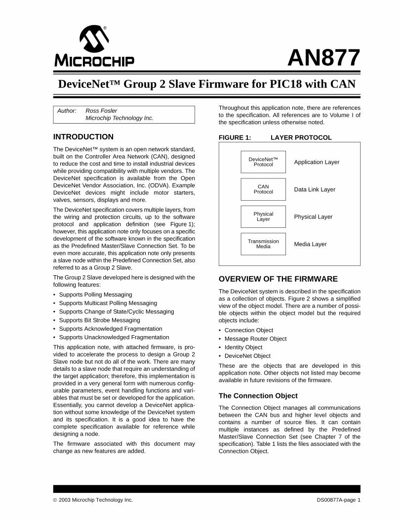
The DeviceNet specification covers multiple layers, fromthe wiring and protection circuits, up to the softwareprotocol and application definition (see Figure 1);however, this application note only focuses on a specificdevelopment of the software known in the specificationas the Predefined Master/Slave Connection Set. To beeven more accurate, this application note only presentsa slave node within the Predefined Connection Set, alsoreferred to as a Group 2 Slave.
The Group 2 Slave developed here is designed with thefollowing features:
• Supports Polling Messaging• Supports Multicast Polling Messaging• Supports Change of State/Cyclic Messaging
• Supports Bit Strobe Messaging• Supports Acknowledged Fragmentation• Supports Unacknowledged Fragmentation
This application note, with attached firmware, is pro-vided to accelerate the process to design a Group 2Slave node but not do all of the work. There are manydetails to a slave node that require an understanding ofthe target application; therefore, this implementation isprovided in a very general form with numerous config-urable parameters, event handling functions and vari-ables that must be set or developed for the application.Essentially, you cannot develop a DeviceNet applica-tion without some knowledge of the DeviceNet systemand its specification. It is a good idea to have thecomplete specification available for reference whiledesigning a node.
The firmware associated with this document maychange as new features are added.
Throughout this application note, there are referencesto the specification. All references are to Volume I ofthe specification unless otherwise noted.
FIGURE 1: LAYER PROTOCOL
OVERVIEW OF THE FIRMWARE
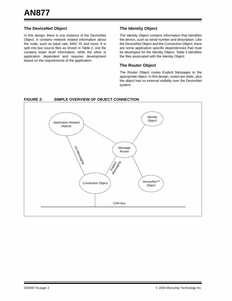
The DeviceNet system is described in the specificationas a collection of objects. Figure 2 shows a simplifiedview of the object model. There are a number of possi-ble objects within the object model but the requiredobjects include:
• Connection Object• Message Router Object• Identity Object
• DeviceNet Object
These are the objects that are developed in thisapplication note. Other objects not listed may becomeavailable in future revisions of the firmware.
The Connection Object
The Connection Object manages all communicationsbetween the CAN bus and higher level objects andcontains a number of source files. It can containmultiple instances as defined by the PredefinedMaster/Slave Connection Set (see Chapter 7 of thespecification). Table 1 lists the files associated with theConnection Object.
Author: Ross FoslerMicrochip Technology Inc.
DeviceNet™Protocol
CANProtocol
PhysicalLayer
TransmissionMedia Media Layer
Physical Layer
Data Link Layer
Application Layer
2003 Microchip Technology Inc. DS00877A-page 1
AN877
The DeviceNet Object
In this design, there is one instance of the DeviceNetObject. It contains network related information aboutthe node, such as baud rate, MAC ID and more. It issplit into two source files as shown in Table 2; one filecontains lower level information, while the other isapplication dependent and requires developmentbased on the requirements of the application.
The Identity Object
The Identity Object contains information that identifiesthe device, such as serial number and description. Likethe DeviceNet Object and the Connection Object, thereare some application specific dependencies that mustbe developed for the Identity Object. Table 3 identifiesthe files associated with the Identity Object.
The Router Object
The Router Object routes Explicit Messages to theappropriate object. In this design, routes are static, plusthe object has no external visibility over the DeviceNetsystem.
FIGURE 2: SIMPLE OVERVIEW OF OBJECT CONNECTION
MessageRouter
Connection Object
IdentityObject
DeviceNet™Object
Application RelatedObjects
CAN bus
I/O M
essaging
Exp
licit
Mes
sagi
ng
DS00877A-page 2 2003 Microchip Technology Inc.

AN877
TABLE 1: CONNECTION OBJECT RELATED FILES
TABLE 2: DeviceNet OBJECT RELATED FILES
TABLE 3: IDENTITY OBJECT RELATED FILES
TABLE 4: ADDITIONAL HELPER FILES
File Name Description
conn.c This file contains several connection managing functions to capture communications events and dispatch them to appropriate instances or other managing functions.
conn1.c This file provides the Predefined Explicit Messaging connection functionality.
conn2.c This file provides the Predefined Polled/Change of State/Cyclic I/O Messaging connection functionality.
conn3.c This file provides the Predefined Bit Strobed I/O Messaging connection functionality.
conn4.c This file provides the Predefined Change of State/Cyclic I/O Messaging connection functionality.
conn5.c This file provides the Predefined Multicast Polled I/O Messaging connection functionality.
conn6.c This file provides the Unconnected Explicit Messaging functionality which looks similar to other regular I/O connections, but does not support all the events and fragmentation.
conn7.c This file provides the Duplicate MAC ID Messaging functionality which looks similar to other regular I/O connections, but does not support all the events and fragmentation.
frag.c This file contains the I/O Fragmentation managing functions.
CAN.C This file contains the abstracted CAN driver routines. The functions are abstract to support the possibility of having a variety of CAN options.
EMM.c This file is referred to as the Explicit Messaging Manager. It contains functions to interface Explicit Messaging to the router. Routing specific information is parsed and placed in the Router Object.
UEMM.c This file is referred to as the Unconnected Explicit Messaging Manager. It contains functions to interface Unconnected Explicit Messaging to the router. However, only the “Allocate” and “Release” commands directed to the DeviceNet Object are allowed; all other messages are ignored.
NASM.c This file contains the Network Access State Machine functions. These functions are bound together with the Identity Object and the Duplicate MAC ID Message.
UsrConn.c Application specific logic for the Connection Object is contained within this file; therefore, this file must be developed for the application.
File Name Description
dnet.c This file contains most of the required logic for the DeviceNet Object. It contains DeviceNet global variables and Explicit Message handling for the commands identified in Section 5-5 of the specification.
UsrDNet.c Logic that depends on the application is contained within this file; therefore, this file must be developed for the application.
File Name Description
ident.c This file contains most of the required logic for the Identity Object. It contains global variables and Explicit Message handling for the commands identified in Volume II, Section 6-2 of the specification.
UsrIdent.c Logic that depends on the application is contained within this file; therefore, this file must be developed for the application.
File Name Description
class.h Defined classes of objects.
errors.h Defined Explicit Messaging errors.
typedefs.h Internal data types.
2003 Microchip Technology Inc. DS00877A-page 3

AN877
THE CONNECTION OBJECT
The Connection Object, as shown in Figure 3, is thelargest and most complex object in the design. Withinthe object, all data and error events must be managedwhich explains the complexity.
All events are received by the managing functionswithin the conn.c file through calls to the CAN driver.The events are decoded and dispatched to the appro-priate instance based on the availability of the connec-tion. Note that an instance of a connection does notexist until it is explicitly created (see Section 5-5 of thespecification). The only two messages that are receivedwithout explicitly instantiating a connection are theUnconnected Explicit Request Message and theDuplicate MAC ID Check Message (see Section 7-2 ofthe specification).
Once instantiated, each instance manages the eventsthat it receives. In general, the events include:
• ConnxCreate – Creates the object• ConnxClose – Closes the object• ConnxTimerEvent – Handles connection
related timers• ConnxRxEvent – Handles received data
• ConnxTxOpenEvent – Handles transmit availability
• ConnxTxEvent – Notification when data has been put on the bus
• ConnxExplicitEvent – Handles Explicit Messaging requests
At the upper level of the Connection Object are addi-tional managers which process the received data forthe instances. This includes Unconnected and Con-nected Explicit Message handling, Network AccessControl (see Chapter 6 of the specification) and theapplication specific I/O.
FIGURE 3: THE CONNECTION OBJECT AND HIGHER MANAGEMENT OBJECTS
Inst. 1(conn1.c)
Inst. 2(conn2.c)
Inst. 3(conn3.c)
Inst. 4(conn4.c)
Inst. 5(conn5.c)
Msg. 6(conn6.c)
Msg. 7(conn7.c)
Tx, Rx, Fragmentation,and Time Managing
Functions(conn.c, frag.c)
UnconnectedExplicit Message
Manager(UEMM.c)
Explicit MessageManager(EMM.c)
Network AccessManager(NASM.c)
Abstract CANDriver Functions
(CAN.C)
User I/OInterface
(UsrConn.c)
DS00877A-page 4 2003 Microchip Technology Inc.
AN877
Internal Connection Object Services
The Connection Object manages I/O connection datamovement to and from the user supplied buffer. It is upto the application to decide how to handle the dataabove the Connection Object.
There are up to four possible predefined instances thatare defined (see Chapter 7 of the specification):
• Polled Messaging• Bit Strobed Messaging• Cyclic/Change of State Messaging• Multicast Polled Messaging
Some basic internal services are provided through theConnection Object for the purpose of managing I/O data.
mConnReadRdy
Query the Connection Object to determine the status of the read buffer of the specified connection number. Returns trueif a message has been received and is waiting in the receive buffer. Valid numbers are 1 through 7; however, onlynumbers 2 through 5 should be used since these are where the I/O connections reside.
Syntax
unsigned char mConnReadRdy (unsigned char hInstance)
Example
if (mConnReadRdy(2)){
// Process application stuffApplicationProcess();// Free the connection to accept more datamConnRead(2);
}
mConnWriteRdy
Query the Connection Object to determine the status of the write buffer of the specified connection number. Returnstrue if the buffer is open to accept new data from transmission. Valid numbers are 1 through 7; however, only numbers2 through 5 should be used since these are where the I/O connections reside.
Syntax
unsigned char mConnWriteRdy (unsigned char hInstance)
Example
if (mConnWriteRdy(2)){
// Process application stuffApplicationProcess();// Release the connection to write the datamConnWrite(2);
}
2003 Microchip Technology Inc. DS00877A-page 5
AN877
mConnRead
Calling this function with the appropriate instance number will indicate to the Connection Object that all data has beenprocessed and the connection should be ready to receive more data.
Syntax
void mConnRead (unsigned char hInstance)
mConnWrite
Calling this function with the appropriate instance number will indicate to the Connection Object that all data has beenloaded into the connection’s buffer for transmitting on the bus.
Syntax
void mConnWrite (unsigned char hInstance)
DS00877A-page 6 2003 Microchip Technology Inc.

AN877
Connection Object EventsThere are events and global registers that cannot bedefined without the application. For this reason, theyare passed up to the UsrConn.c object for applicationspecific processing. Code must be developed in this fileto manage appropriate events.
Upon instantiation, a “Create Event” is generated withthe appropriate instance number passed. This eventmust be handled to set up some application dependentattributes. The attributes that must be set up are:
• Produced path• Consumed path• Produced path length• Consumed path length• Pointer to the consumed data• Pointer to the produced data• Length of the consumed data• Length of the produced data
Like the “Create Event”, there is also a “Close Event”when the connection is closed. This is provided to notifythe application when the connection is no longer available.
Two other events that may or may not necessarily beset up are the “Rx Event” and the “Tx Event”. Theseevents are generated when data has been transmittedor received. These are provided for any applicationspecific event handling; however, they do not neces-sarily need to be handled as an event. Receive andtransmit can be polled through normal ConnectionObject functions.
One other event is the “Set Attribute Event”. This eventmust be handled for any attribute that is not entirelydependent on the Connection Object alone. Theattributes are:
• _ATTRIB_CLASS_TRIGGER
• _ATTRIB_PRODUCED_CONN_PATH
• _ATTRIB_CONSUMED_CONN_PATH
• _ATTRIB_PRODUCED_CONN_SIZE
Not all attributes are required to be settable; however,the event must be handled to generate an error if theevent occurs.
UsrConnCreateEvent
This event function is called when a connection is created by an allocate request. The instance number is passed indi-cating the source of the event. This event is an indication to the application to provide resources necessary for the con-nection to function. Other than application specific resources, buffer space and path information must be provided. Ifresources are not available, then the application should return ‘0’ to this event; otherwise, the application should returnany other value to allow the creation of the connection.
Syntaxunsigned char UsrConnCreateEvent (unsigned char hInstance)
Exampleunsigned char UsrConnCreateEvent(unsigned char hInstance){
switch (hInstance){
case 2:// Set path information according to Appendix I // of the DeviceNet specification// Set the connection sizesuConn2.attrib.consumed_con_size.word = 13;uConn2.attrib.produced_con_size.word = 20;
// Set the pointers to the buffersuConn2.rx.pMsg = uConn2RxBuffer;uConn2.tx.pMsg = uConn2TxBuffer;
return(1);case 3:
// Set path and connection informationreturn(1);
case 4:// Set path and connection informationreturn(1);
case 5:// Set path and connection informationreturn(1);
}}
2003 Microchip Technology Inc. DS00877A-page 7

AN877
UsrConnCloseEvent
This event function is called when a connection is closed by a time-out or release request. The instance number ispassed indicating the source of the event. This event is an indication to the application to release any allocatedresources.
Syntax
void UsrConnCloseEvent (unsigned char hInstance)
UsrConnRxDataEvent
This event function is called when a connection has received data. The instance number is passed indicating the sourceof the event.
Syntax
void UsrConnRxDataEvent (unsigned char hInstance)
UsrConnTxDataEvent
This event function is called when a connection has transmitted its data. The instance number is passed indicating thesource of the event.
Syntax
void UsrConnTxDataEvent (unsigned char hInstance)
UsrConnSetAttribEvent
This event is generated when an attribute that is defined by the application has been requested to be changed by anExplicit Message. The application must decode the attribute and generate an appropriate response to the request. Referto the Router Object for details on internal services to handle Explicit Message responses.
Syntax
void UserConnSet AttribEvent (unsigned char hInstance)
Example
switch (mRouteGetAttributeID()){
case _ATTRIB_CLASS_TRIGGER:// Process request to set this attributebreak;
case _ATTRIB_PRODUCED_CONN_PATH:// Process request to set this attributebreak;
case _ATTRIB_CONSUMED_CONN_PATH:// Process request to set this attributebreak;
case _ATTRIB_PRODUCED_CONN_SIZE:// Process request to set this attributebreak;
}
DS00877A-page 8 2003 Microchip Technology Inc.
AN877
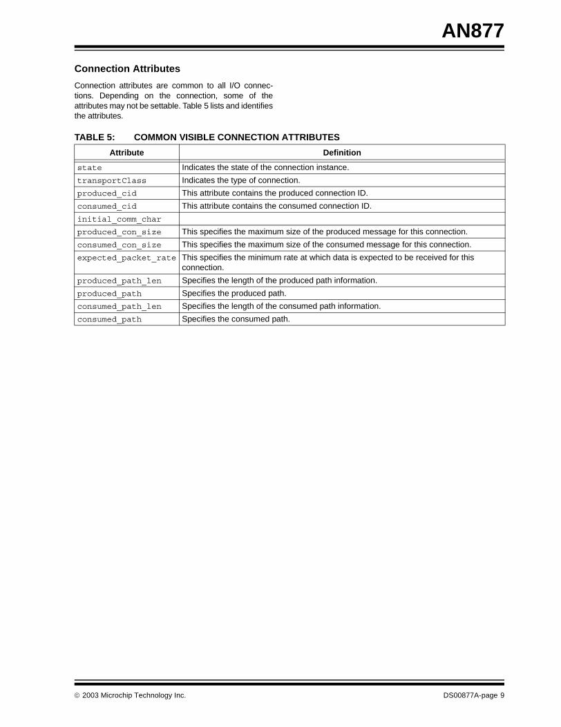
Connection Attributes
Connection attributes are common to all I/O connec-tions. Depending on the connection, some of theattributes may not be settable. Table 5 lists and identifiesthe attributes.
TABLE 5: COMMON VISIBLE CONNECTION ATTRIBUTES
Attribute Definition
state Indicates the state of the connection instance.
transportClass Indicates the type of connection.
produced_cid This attribute contains the produced connection ID.
consumed_cid This attribute contains the consumed connection ID.
initial_comm_char
produced_con_size This specifies the maximum size of the produced message for this connection.
consumed_con_size This specifies the maximum size of the consumed message for this connection.
expected_packet_rate This specifies the minimum rate at which data is expected to be received for this connection.
produced_path_len Specifies the length of the produced path information.
produced_path Specifies the produced path.
consumed_path_len Specifies the length of the consumed path information.
consumed_path Specifies the consumed path.
2003 Microchip Technology Inc. DS00877A-page 9
AN877
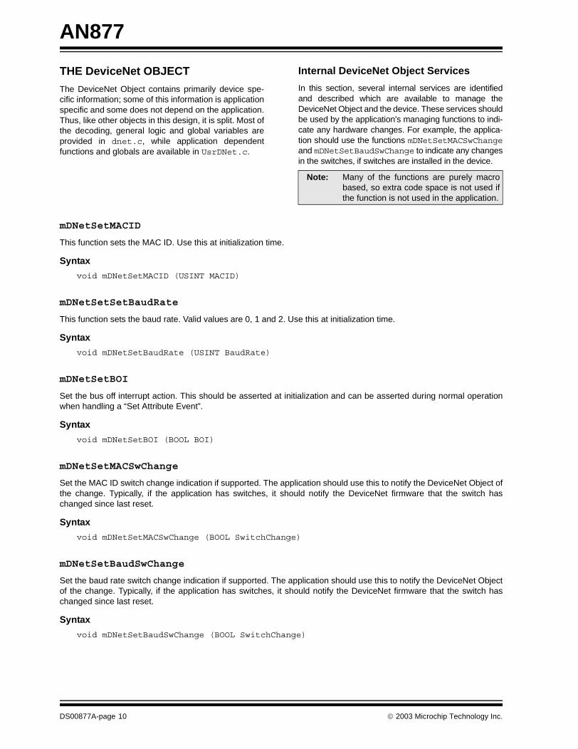
THE DeviceNet OBJECT
The DeviceNet Object contains primarily device spe-cific information; some of this information is applicationspecific and some does not depend on the application.Thus, like other objects in this design, it is split. Most ofthe decoding, general logic and global variables areprovided in dnet.c, while application dependentfunctions and globals are available in UsrDNet.c.
Internal DeviceNet Object Services
In this section, several internal services are identifiedand described which are available to manage theDeviceNet Object and the device. These services shouldbe used by the application’s managing functions to indi-cate any hardware changes. For example, the applica-tion should use the functions mDNetSetMACSwChangeand mDNetSetBaudSwChange to indicate any changesin the switches, if switches are installed in the device.
mDNetSetMACID
This function sets the MAC ID. Use this at initialization time.
Syntax
void mDNetSetMACID (USINT MACID)
mDNetSetSetBaudRate
This function sets the baud rate. Valid values are 0, 1 and 2. Use this at initialization time.
Syntax
void mDNetSetBaudRate (USINT BaudRate)
mDNetSetBOI
Set the bus off interrupt action. This should be asserted at initialization and can be asserted during normal operationwhen handling a “Set Attribute Event”.
Syntax
void mDNetSetBOI (BOOL BOI)
mDNetSetMACSwChange
Set the MAC ID switch change indication if supported. The application should use this to notify the DeviceNet Object ofthe change. Typically, if the application has switches, it should notify the DeviceNet firmware that the switch haschanged since last reset.
Syntax
void mDNetSetMACSwChange (BOOL SwitchChange)
mDNetSetBaudSwChange
Set the baud rate switch change indication if supported. The application should use this to notify the DeviceNet Objectof the change. Typically, if the application has switches, it should notify the DeviceNet firmware that the switch haschanged since last reset.
Syntax
void mDNetSetBaudSwChange (BOOL SwitchChange)
Note: Many of the functions are purely macrobased, so extra code space is not used ifthe function is not used in the application.
DS00877A-page 10 2003 Microchip Technology Inc.

AN877
mDNetSetMACSwValue
Set the MAC ID switch value if supported. The application should use this to notify the DeviceNet Object of the switchvalue.
Syntax
void mDNetSetMACSwValue (USINT SwitchValue)
mDNetSetBaudSwValue
Set the baud rate switch value if supported. The application should use this to notify the DeviceNet Object of the switchvalue.
Syntax
void mDNetSetBaudSwValue (USINT SwitchValue)
mDNetGetMACID
Get the current MAC ID value stored in the DeviceNet Object.
Syntax
USINT mDNetGetMACID ()
mDNetGetBaudRate
Get the current baud rate value stored in the DeviceNet Object.
Syntax
USINT mDNetGetBaudRate()
mDNetGetBOI
Get the current bus off interrupt value stored in the DeviceNet Object.
Syntax
BOOL mDNetGetBOI ()
mDNetGetBusOffCount
Get the current bus off count value stored in the DeviceNet Object. This value is updated by the Connection Object ErrorManagement function.
Syntax
USINT mDNetGetBusOffCount ()
mDNetGetAllocChoice
Get the current allocation choice byte. This value is changed based on the requests from the server and the internalwatchdog timers. This could be used internally to get an indication of what connection has been allocated.
Syntax
USINT mDNetGetAllocChoice ()
2003 Microchip Technology Inc. DS00877A-page 11
AN877
mDNetGetMasterMACID
Get the current allocated Master MAC ID. Valid values are 0 to 63 and 255. A value of 255 indicates that no client hasallocated this node.
Syntax
USINT mDNetGetMasterMACID ()
mDNetMACSwChange
Get the stored MAC ID switch change value.
Syntax
void mDNetSetBOI (unsigned char MACID)
mDNetBaudSwChange
Get the stored baud rate switch change value.
Syntax
void mDNetSetBOI (unsigned char MACID)
mDNetGetMACSwValue
Get the stored MAC ID switch value.
Syntax
USINT mDNetGetMACSwValue ()
mDNetGetBaudSwValue
Get the stored baud rate switch value.
Syntax
USINT mDNetGetBaudSwValue ()
DS00877A-page 12 2003 Microchip Technology Inc.

AN877
DeviceNet Object Events
There are two events that must be handled by the appli-cation that occur in the DeviceNet Object, which arelisted below.
Within the UsrDNetInitEvent function, severalattributes specific to the DeviceNet Object must be set.For example, the MAC ID and the baud rate can be
switch values, or internal values stored in memory,depending on the application design. Thus, these initial-izations are left to the application designer. The samesituation applies to the UsrDNetSetAttribEventfunction. Refer to Section 5-5 of the specification forinformation on the DeviceNet Object. The specificationidentifies the settable attributes and the conditions thatenable the settable attributes.
UsrDNetInitEvent
This event occurs when the DeviceNet Object is initialized. A number of attributes must be set up.
Syntax
void UsrDNetInitEvent (void)
Example
void UsrDNetInitEvent(void){
mDNetSetMACID(12);mDNetSetBaudRate(0);mDNetSetBOI(0);mDNetSetMACSwChange(0);mDNetSetBaudSwChange(0);mDNetSetMACSwValue(0);mDNetSetBaudSwValue(0);
}
UsrDNetSetAttribEvent
The “Set Attribute Event” occurs when the setting of an attribute cannot be handled internally because of someapplication dependency.
Syntax
void UsrDNetSetAttribEvent (void)
Example
void UsrDNetSetAttribEvent(void){
switch (mRouteGetAttributeID()){
case _ATTRIB_MAC_ID:// Application code to handle setting MAC IDbreak;
case _ATTRIB_BAUD_RATE:// Application code to handle setting baud ratebreak;
case _ATTRIB_BOI:// Application code to handle setting BOIbreak;
}}
2003 Microchip Technology Inc. DS00877A-page 13
AN877
THE IDENTITY OBJECT
The Identity Object contains device identification infor-mation; some of this information is application specificand some does not depend on the application. Thus,like other objects in this design, it is split. Most of thedecoding, general logic and global variables areprovided in ident.c, while application dependentfunctions and globals are available in UsrIdent.c.
Identity Object Events
UsrIdentityCommunicationFaultEvent
This event is generated when communications has faulted (i.e., the bus off count has exceeded 255). Refer to Chapter 6of the DeviceNet specification.
Syntax
void UsrIdentityCommunicationFaultEvent(void)
UsrIdentityFaultEvent
This event occurs when the Network Access State Machine has been corrupted. If this ever occurs, a Reset is probablynecessary.
Syntax
void UsrIdentityFaultEvent(void)
UsrIdentityReset
This function is called when a Reset has been requested. This occurs through an Explicit Messaging request.
Syntax
void UsrIdentityReset(void)
Example
void UsrIdentityReset(void){
USINT resetData;
// Ignore the first byte (it is actually the attribute ID) mRouteGetByte();
// Verify that one byte has been receivedif (mRouteTestValidInputDataLen(1)){
// Get the data (6-2.3.1)resetData = mRouteGetByte();
if (resetData == 0){
// Perform a soft reset}else if (resetData == 1){
// Perform an ‘out of the box’ reset}
}}
DS00877A-page 14 2003 Microchip Technology Inc.

AN877
UsrIdentityInitEvent
This is the initialization event. The identity globals must be set up in this event.
Syntax
void UsrIdentityInitEvent(void)
Example
ROM unsigned char cProductName[] = {"Microchip Device"};
void UsrIdentityInitEvent(void){
mIdentitySetVendorID(12345);mIdentitySetDeviceType(2);mIdentitySetProductCode(3);mIdentitySetMajorRevision(1);mIdentitySetMinorRevision(0);mIdentitySetStatus(0);mIdentitySetSerial(28933892);mIdentitySetNameP(cProductName);mIdentitySetNameLen(sizeof(cProductName));
}
2003 Microchip Technology Inc. DS00877A-page 15

AN877
Internal Identity Object Services
The following identifies and describes several internalservices that are available to manage the IdentityObject and the device. These services should be usedby the application’s managing functions to indicate anychanges related to the Identity Object, most notably thestatus of the device. For example, the applicationshould use the function, mIdentitySetStatus, toindicate any application level Fault conditions. See thefunctions below.
mIdentitySetVendorID
Use this to set the vendor ID of the node. This number is assigned by ODVA.
Syntax
void mIdentitySetVendorID (UINT VendorID)void mIdentitySetVendorIDL (USINT VendorID)void mIdentitySetVendorIDH (USINT VendorID)
mIdentityGetVendorID
Use this to get the stored vendor ID.
Syntax
UINT mIdentityGetVendorID (void)USINT mIdentityGetVendorIDL (void)USINT mIdentityGetVendorIDH (void)
mIdentitySetDeviceType
Use this to set the device type.
Syntax
void mIdentitySetDeviceType (UINT DeviceType)void mIdentitySetDeviceTypeL (USINT DeviceType)void mIdentitySetDeviceTypeH (USINT DeviceType)
mIdentityGetDeviceType
Use this to get the device type.
Syntax
UINT mIdentityGetDeviceType (void)USINT mIdentityGetDeviceTypeL (void)USINT mIdentityGetDeviceTypeH (void)
mIdentitySetProductCode
Set the product code.
Syntax
void mIdentitySetProductCode (UINT ProductCode)void mIdentitySetProductCodeL (USINT ProductCode)void mIdentitySetProductCodeH (USINT ProductCode)
DS00877A-page 16 2003 Microchip Technology Inc.
AN877
mIdentityGetProductCode
Get the product code.
Syntax
UINT mIdentityGetProductCode (void)USINT mIdentityGetProductCodeL (void)USINT mIdentityGetProductCodeH (void)
mIdentitySetMajorRevision
Set the major revision.
Syntax
void mIdentitySetMajorRevision (USINT MajorRev)
mIdentityGetMajorRevision
Get the major revision.
Syntax
USINT mIdentityGetMajorRevision (void)
mIdentitySetMinorRevision
Set the minor revision.
Syntax
void mIdentitySetMinorRevision (USINT MinorRev)
mIdentityGetMinorRevision
Get the minor revision.
Syntax
USINT mIdentityGetMinorRevision (void)
mIdentitySetSerial
Set the serial number.
Syntax
void mIdentitySetSerial (UDINT SerialNo)void mIdentitySetSerialL (USINT SerialNo)void mIdentitySetSerialH (USINT SerialNo)void mIdentitySetSerialUL (USINT SerialNo)void mIdentitySetSerialUH (USINT SerialNo)
2003 Microchip Technology Inc. DS00877A-page 17
AN877
mIdentityGetSerial
Get the serial number.
Syntax
UDINT mIdentityGetSerial (void)USINT mIdentityGetSerialL (void)USINT mIdentityGetSerialH (void)USINT mIdentityGetSerialUL (void)USINT mIdentityGetSerialUH (void)
mIdentitySetStatus
Set the status of the device. This must be set by the application to indicate the current status of the device (seeSection 6-2.2 of the specification).
Syntax
void mIdentitySetStatus (WORD DevStat)void mIdentitySetStatusL (unsigned char DevStat)void mIdentitySetStatusH (unsigned char DevStat)
mIdentityGetStatus
Get the status of the device.
Syntax
WORD mIdentityGetStatus (void)unsigned char mIdentityGetStatusL (void)unsigned char mIdentityGetStatusH (void)
mIdentitySetNameP
Set a ROM pointer to the name of the device.
Syntax
void mIdentitySetNameP (ROM unsigned char pName)
mIdentitySetNameLen
Set the length of the name.
Syntax
void mIdentitySetNameLen (unsigned char NameLen)
DS00877A-page 18 2003 Microchip Technology Inc.

AN877
THE ROUTER OBJECT
Although the Router Object has no external visibilitythrough Explicit Messaging, it has many internalfunctions for routing Explicit Message data. Thesefunctions are listed and described in the “InternalRouting Services” section.
Handling Explicit Messaging
Every application object that has attributes and ser-vices has an Explicit Message handling function thatdecodes the path information. The router automaticallyparses the appropriate information and makes it avail-able to the application. Plus, there are a number offunctions that are also available. All of the possiblefunctions are listed in the “Internal Routing Services”section. Following are some of the more importantinternal functions:
• mRoutePutByte – Put a byte into the response buffer and automatically adjust some internal pointers to the next byte in the buffer.
• mRouteGetByte – Read a byte from the receive buffer and automatically adjust to the next byte in the buffer.
• mRouteTestValidInputDataLen – Test the length of the attribute data against the expected data length.
• mRoutePutError – Set the appropriate error response.
• mRouteGetServiceID – Get the service ID.• mRouteGetInstanceID – Get the instance ID.• mRouteGetAttributeID – Get the attribute ID.
• mRouteGetInBufferPtr – Get the pointer to the buffer.
• mRouteGetInBufferDataLength – Get the amount of data in the input buffer.
• mRouteGetOutBufferPtr – Get a pointer to the output buffer.
• mRouteGetOutBufferLength – Get the maximum length of the output buffer.
Refer to the source code for examples on handlingExplicit Messaging events.
Internal Routing Services
mRoutePutByte
Put a byte into the buffer to be transmitted by the Explicit Messaging connection. Internal pointers are maintainedautomatically. Thus, multiple writes will write bytes sequentially in the buffer.
Syntax
void mRoutePutByte (USINT dataByte)
mRouteGetByte
Get a byte from the received Explicit Messaging connection buffer. Internal pointers are maintained automatically. Thus,multiple reads will read bytes sequentially from the buffer.
Syntax
USINT mRouteGetByte (void)
mRouteTestValidInputDataLen
Verify the length of the input data. An error response is automatically generated if the boundary conditions are not met.
Syntax
unsigned char mRouteTestValidInputDataLen (unsigned char len)
2003 Microchip Technology Inc. DS00877A-page 19
AN877
mRouteTestNonValidInputDataLen
Verify the length of the input data. An error response is automatically generated if the boundary conditions are not met.
Syntax
unsigned char mRouteTestNonValidInputDataLen (unsigned char len)
mRoutePutError
Put an error response in the buffer. Refer to errors.h and the specification for a list of known errors.
Syntax
void mRoutePutError (USINT errorCode)
mRouteRxLen
Get the receive data length.
Syntax
USINT mRouteRxLen (void)
mRouteTxLen
Get the transmit data length.
Syntax
USINT mRouteTxLen (void)
mRouteGetHeader
Get the header of the received Explicit Message.
Syntax
USINT mRouteGetHeader (void)
mRouteGetServiceID
Get the service ID of the received Explicit Message.
Syntax
USINT mRouteGetServiceID (void)
mRouteGetClassID
Get the class ID of the received Explicit Message.
Syntax
USINT mRouteGetClassID (void)UINT mRouteGetClassID (void)
DS00877A-page 20 2003 Microchip Technology Inc.
AN877
mRouteGetInstanceID
Get the instance ID of the received Explicit Message.
Syntax
USINT mRouteGetInstanceID (void)UINT mRouteGetInstanceID (void)
mRouteGetAttributeID
Get the attribute ID of the received Explicit Message.
Syntax
USINT mRouteGetAttributeID (void)
mRouteGetInBufferPtr
Get the pointer to the input buffer.
Syntax
USINT * mRouteGetInBufferPtr (void)
mRouteGetOutBufferPtr
Get the pointer to the output buffer.
Syntax
USINT * mRouteGetOutBufferPtr (void)
mRouteGetInBufferLength
Get the length of the input buffer.
Syntax
USINT mRouteGetInBufferLength (void)
mRouteGetInBufferDataLength
Get the length of data in the input buffer.
Syntax
USINT mRouteGetInBufferDataLength (void)
mRouteGetOutBufferLength
Get the length of the output buffer.
Syntax
USINT mRouteGetOutBufferLength (void)
mRouteGetOutBufferDataLength
Get the length of the data in the output buffer.
Syntax
USINT mRouteGetOutBufferDataLength (void)
2003 Microchip Technology Inc. DS00877A-page 21

AN877
mRoutePutServiceID
Set the service ID. Typically this is used only when changing the Explicit Message response to an error response.
Syntax
void mRoutePutServiceID (USINT ServiceID)
mRoutePutInBufferPtr
Set the input buffer pointer.
Syntax
void mRoutePutInBufferPtr (USINT * pInBuf)
mRoutePutOutBufferPtr
Set the output buffer pointer.
Syntax
void mRoutePutOutBufferPtr (USINT * pOutBuf)
mRoutePutInBufferLength
Set the input buffer length.
Syntax
void mRoutePutInBufferLength (USINT length)
mRoutePutInBufferDataLength
Set the length of the data in the input buffer.
Syntax
void mRoutePutInBufferDataLength (USINT length)
mRoutePutOutBufferLength
Set the output buffer length.
Syntax
void mRoutePutOutBufferLength (USINT length)
mRoutePutOutBufferDataLength
Set the length of data in the output buffer.
Syntax
void mRoutePutOutBufferDataLength (USINT length)
DS00877A-page 22 2003 Microchip Technology Inc.
AN877
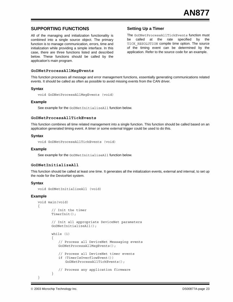
SUPPORTING FUNCTIONSAll of the managing and initialization functionality iscombined into a single source object. The primaryfunction is to manage communication, errors, time andinitialization while providing a simple interface. In thiscase, there are three functions listed and describedbelow. These functions should be called by theapplication’s main program.
Setting Up a Timer
The GoDNetProcessAllTickEvents function mustbe called at the rate specified by theTICK_RESOLUTION compile time option. The sourceof the timing event can be determined by theapplication. Refer to the source code for an example.
GoDNetProcessAllMsgEvents
This function processes all message and error management functions, essentially generating communications relatedevents. It should be called as often as possible to avoid missing events from the CAN driver.
Syntax
void GoDNetProcessAllMsgEvents (void)
Example
See example for the GoDNetInitializeAll function below.
GoDNetProcessAllTickEvents
This function combines all time related management into a single function. This function should be called based on anapplication generated timing event. A timer or some external trigger could be used to do this.
Syntax
void GoDNetProcessAllTickEvents (void)
Example
See example for the GoDNetInitializeAll function below.
GoDNetInitializeAll
This function should be called at least one time. It generates all the initialization events, external and internal, to set upthe node for the DeviceNet system.
Syntaxvoid GoDNetInitializeAll (void)
Example
void main(void){
// Init the timerTimerInit();
// Init all appropriate DeviceNet parametersGoDNetInitializeAll();
while (1){
// Process all DeviceNet Messaging eventsGoDNetProcessAllMsgEvents();
// Process all DeviceNet timer eventsif (TimerIsOverflowEvent())
GoDNetProcessAllTickEvents();
// Process any application firmware}
}
2003 Microchip Technology Inc. DS00877A-page 23

AN877
COMPILE TIME SETUP
There are several compile time options that must be setto configure the DeviceNet firmware. They are listedand described in Table 6.
TABLE 6: COMPILE TIME OPTIONS
Option Definition
B125k_BRG1_SJW
Set the BRG values to achieve 125k for the desired clock frequency. Refer to the PIC18FXX8 device data sheet (DS41159) for information on the CAN module.
B125k_BRG1_PRESCALE
B125k_BRG2_SEG2PHTS
B125k_BRG3_WAKFIL
B125k_BRG2_SEG1PH
B125k_BRG3_SEG2PH
B125k_BRG2_PRSEG
B125k_BRG2_SAM
B250k_BRG1_SJW
Set the BRG values to achieve 250k for the desired clock frequency. Refer to the PIC18FXX8 device data sheet (DS41159) for information on the CAN module.
B250k_BRG1_PRESCALE
B250k_BRG2_SEG2PHTS
B250k_BRG3_WAKFIL
B250k_BRG2_SEG1PH
B250k_BRG3_SEG2PH
B250k_BRG2_PRSEG
B250k_BRG2_SAM
B500k_BRG1_SJW
Set the BRG values to achieve 500k for the desired clock frequency. Refer to the PIC18FXX8 device data sheet (DS41159) for information on the CAN module.
B500k_BRG1_PRESCALE
B500k_BRG2_SEG2PHTS
B500k_BRG3_WAKFIL
B500k_BRG2_SEG1PH
B500k_BRG3_SEG2PH
B500k_BRG2_PRSEG
B500k_BRG2_SAM
CLASS_WIDTH_16BIT If this parameter is true, then the Router Object will assume 16-bit class ID for all connected Explicit Messages; otherwise, 8-bit is default.
INSTANCE_WIDTH_16BIT If this parameter is true, then the Router Object will assume 16-bit instance ID for all connected Explicit Messages; otherwise, 8-bit is default.
TICK_RESOLUTION Set the tick resolution that will be supplied to the firmware. The resolution must be 1, 2, 4, 8, 16 or 32 ms.
SUPPORT_POLLED Enable support for Polled I/O Messaging.
SUPPORT_BIT_STROBED Enable support for Bit Strobed I/O Messaging.
SUPPORT_MULTICAST_POLL Enable support for Multicast Polled I/O Messaging.
SUPPORT_COS Enable support for COS I/O Messaging.
SUPPORT_CYCLIC Enable support for Cyclic I/O Messaging.
SUPPORT_COS_BOTH_DIR Enable support for COS/Cyclic I/O Messaging for both directions.
FRAGMENTATION_UNACK Enable fragmentation support for I/O Messages.
FRAGMENTATION_ACK Enable fragmentation support for Explicit Messages.
EXPLICIT_ACK_TIMER Acknowledge time-out for fragmented transmission.
CONN_EXPLICIT_RX_SIZE Set the receive buffer size for Explicit Messages.
DS00877A-page 24 2003 Microchip Technology Inc.

AN877
CONN_EXPLICIT_TX_SIZE Set the transmit buffer size for Explicit Messages.
CONN_POLLED_RX_FRAG Allow fragmentation for Receive Polled Messages.
CONN_POLLED_TX_FRAG Allow fragmentation for Transmit Polled Messages.
CONN_MULTICAST_RX_FRAG Allow fragmentation for Receive Multicast Polled Messages.
CONN_MULTICAST_TX_FRAG Allow fragmentation for Transmit Multicast Polled Messages.
CONN_COS_CYCLIC_RX_FRAG Allow fragmentation for Receive COS/Cyclic Messages.
CONN_COS_CYCLIC_TX_FRAG Allow fragmentation for Transmit COS/Cyclic Messages.
ALLOW_MAC_ID
Enable visibility of these parameters within the DeviceNet Object.
ALLOW_BAUD_RATE
ALLOW_BOI
ALLOW_BUS_OFF_COUNT
ALLOW_ATTRIB_ALLOC_INFO
ALLOW_MAC_ID_SW_CH
ALLOW_BAUD_RATE_SW_CH
ALLOW_MAC_ID_SW_VAL
ALLOW_BAUD_RATE_SW_VAL
SETTABLE_BUS_OFF_COUNT
Enable settability of these parameters within the DeviceNet Object.SETTABLE_BOI
SETTABLE_BAUD_RATE
SETTABLE_MAC_ID
CLASS_USER_DEFINED_1
These options set the application specific Explicit Messaging information for the Router Object. The first parameter is the class ID and the second is the name of the Explicit Message handling function. A class ID of ‘0’ is considered non-existent.
CLASS_USER_DEFINED_1_NAME
CLASS_USER_DEFINED_2
CLASS_USER_DEFINED_2_NAME
CLASS_USER_DEFINED_3
CLASS_USER_DEFINED_3_NAME
CLASS_USER_DEFINED_4
CLASS_USER_DEFINED_4_NAME
CLASS_USER_DEFINED_5
CLASS_USER_DEFINED_5_NAME
CLASS_USER_DEFINED_6
CLASS_USER_DEFINED_6_NAME
CLASS_USER_DEFINED_7
CLASS_USER_DEFINED_7_NAME
CLASS_USER_DEFINED_8
CLASS_USER_DEFINED_8_NAME
TABLE 6: COMPILE TIME OPTIONS (CONTINUED)
Option Definition
2003 Microchip Technology Inc. DS00877A-page 25

AN877
ABOUT THE CAN DRIVER
The Connection Object makes calls to the CAN driverto set up communications and to capture the necessaryevents, such as receive, transmit, and bus off. Thedriver provided is only a very simple form of driver. Thefunctionality is heavily hardware dependent. A muchmore complex driver is possible if the latency and pro-cessing requirements become more stringent in theapplication. The following is a list of driver functionscalled by the Connection Object:
CANOpen
Open communications over CAN.
Syntax
NEAR unsigned char CANOpen(void)
CANClose
Close communications over CAN.
Syntax
NEAR unsigned char CANClose(void)
CANIsOpen
Query to determine if communications are open.
Syntax
NEAR unsigned char CANNIsOpen(void)
CANSetFilter
Set a filter. This is a request, thus the driver may not always be able to completely filter an entire CAN ID.
Syntax
NEAR unsigned char CANSetFilter(NEAR unsigned int filterID)
CANClrFilter
Clear a filter. This is a request, thus the driver may not always be able to completely remove filtering of an entire CAN ID.
Syntax
NEAR unsigned char CANClrFilter(NEAR unsigned int filterID)
CANSetBitRate
Set the bit rate for communications. The format for this follows:
DeviceNet: 0 = 125 kbps, 1 = 250 kbps, 2 = 500 kbps
This function will only work if communication is off-line.
Syntax
NEAR unsigned char CANSetBitRate(NEAR unsigned char bitrate)
DS00877A-page 26 2003 Microchip Technology Inc.

AN877
CANIsBusError
Check for a bus off error.
Syntax
NEAR unsigned char CANIsBusError(void)
CANIsRxRdy
Check to see if data is available.
Syntax
NEAR unsigned char CANIsRxRdy(void)
CANRead
Indicate to the driver that all data has been read. This should allow the driver to use the released resources to receivemore data.
Syntax
void CANRead(void)
CANIsTxRdy
Check to see if a buffer is available.
Syntax
NEAR unsigned char CANIsTxRdy(void)
CANIsMsgSent
Return the tag of the message that was placed on the bus.
Syntax
NEAR unsigned char CANIsMsgSent(void)
CANSend
Indicate to the driver that data has been loaded and is ready to send.
Syntax
void CANSend(NEAR unsigned char txTag)
CANGetRxCID
Get the received CAN ID.
Syntax
NEAR unsigned int CANGetRxCID(void)
CANGetRxCnt
Get the received count.
Syntax
NEAR unsigned char CANGetRxCnt(void)
2003 Microchip Technology Inc. DS00877A-page 27
AN877
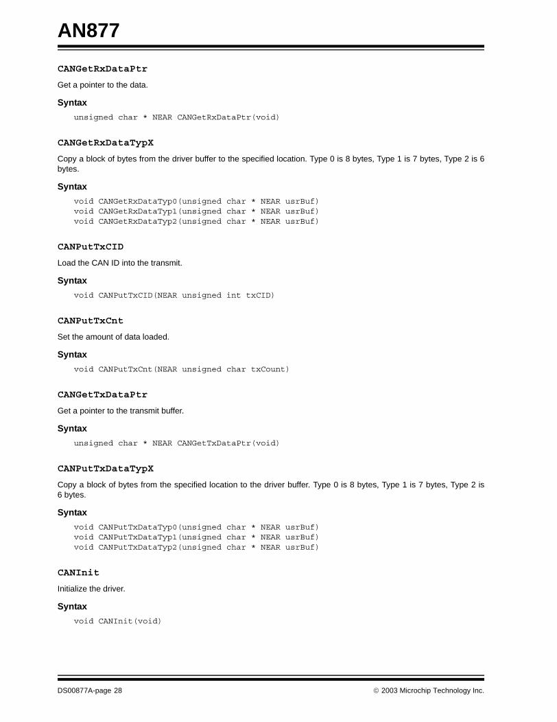
CANGetRxDataPtr
Get a pointer to the data.
Syntax
unsigned char * NEAR CANGetRxDataPtr(void)
CANGetRxDataTypX
Copy a block of bytes from the driver buffer to the specified location. Type 0 is 8 bytes, Type 1 is 7 bytes, Type 2 is 6bytes.
Syntax
void CANGetRxDataTyp0(unsigned char * NEAR usrBuf)void CANGetRxDataTyp1(unsigned char * NEAR usrBuf)void CANGetRxDataTyp2(unsigned char * NEAR usrBuf)
CANPutTxCID
Load the CAN ID into the transmit.
Syntax
void CANPutTxCID(NEAR unsigned int txCID)
CANPutTxCnt
Set the amount of data loaded.
Syntax
void CANPutTxCnt(NEAR unsigned char txCount)
CANGetTxDataPtr
Get a pointer to the transmit buffer.
Syntax
unsigned char * NEAR CANGetTxDataPtr(void)
CANPutTxDataTypX
Copy a block of bytes from the specified location to the driver buffer. Type 0 is 8 bytes, Type 1 is 7 bytes, Type 2 is6 bytes.
Syntax
void CANPutTxDataTyp0(unsigned char * NEAR usrBuf)void CANPutTxDataTyp1(unsigned char * NEAR usrBuf)void CANPutTxDataTyp2(unsigned char * NEAR usrBuf)
CANInit
Initialize the driver.
Syntax
void CANInit(void)
DS00877A-page 28 2003 Microchip Technology Inc.
AN877
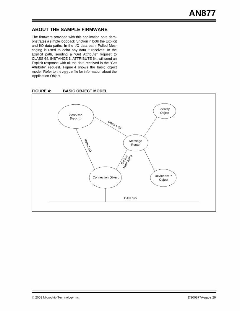
ABOUT THE SAMPLE FIRMWARE
The firmware provided with this application note dem-onstrates a simple loopback function in both the Explicitand I/O data paths. In the I/O data path, Polled Mes-saging is used to echo any data it receives. In theExplicit path, sending a “Get Attribute” request toCLASS 64, INSTANCE 1, ATTRIBUTE 64, will send anExplicit response with all the data received in the “GetAttribute” request. Figure 4 shows the basic objectmodel. Refer to the App.c file for information about theApplication Object.
FIGURE 4: BASIC OBJECT MODEL
MessageRouter
Connection Object
IdentityObject
DeviceNet™Object
Loopback(App.c)
CAN bus
Polled I/O
Exp
licit
Mes
sagi
ng
Class = 64
2003 Microchip Technology Inc. DS00877A-page 29
AN877
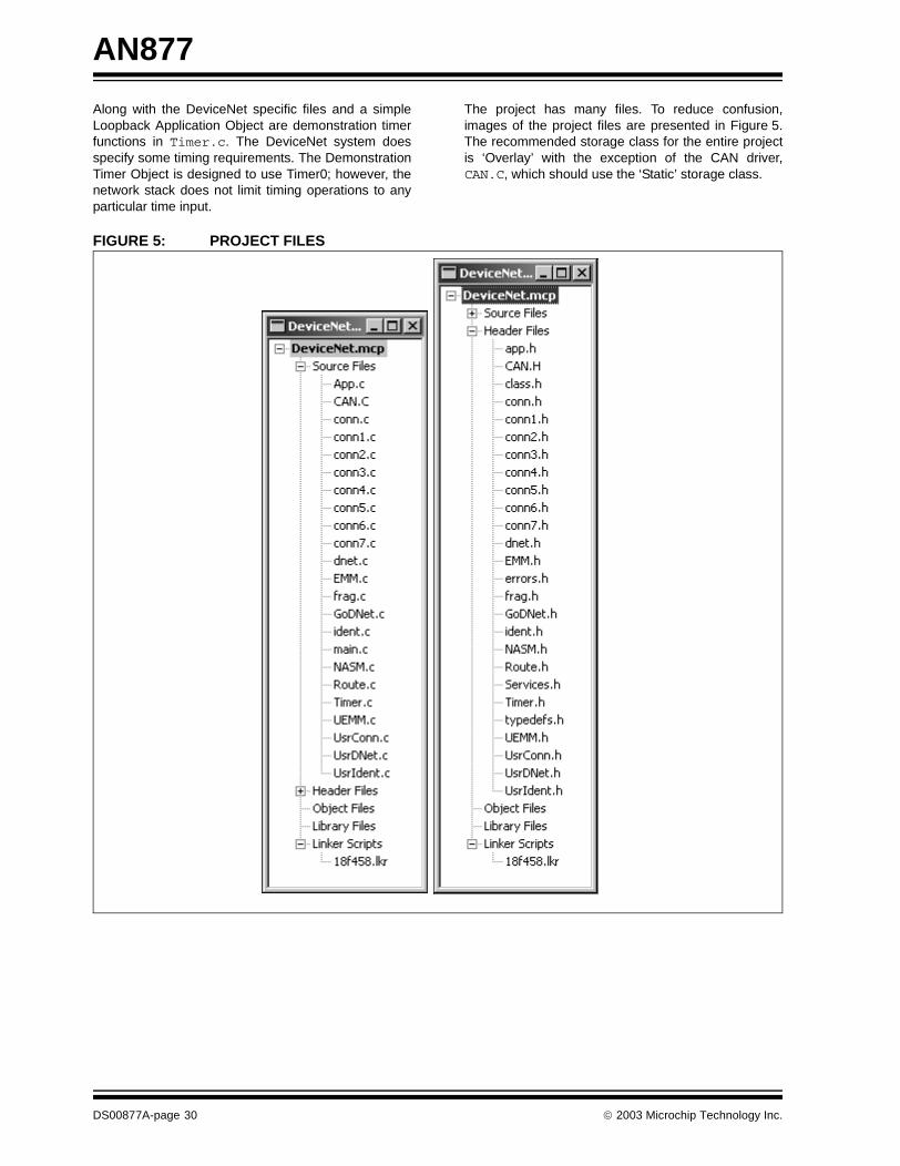
Along with the DeviceNet specific files and a simpleLoopback Application Object are demonstration timerfunctions in Timer.c. The DeviceNet system doesspecify some timing requirements. The DemonstrationTimer Object is designed to use Timer0; however, thenetwork stack does not limit timing operations to anyparticular time input.
The project has many files. To reduce confusion,images of the project files are presented in Figure 5.The recommended storage class for the entire projectis ‘Overlay’ with the exception of the CAN driver,CAN.C, which should use the ‘Static’ storage class.
FIGURE 5: PROJECT FILES
DS00877A-page 30 2003 Microchip Technology Inc.

AN877
FUTURE OBJECTS
There are two objects that may become available infuture revisions of the associated source code that arenot currently available. They are the Assembly Objectand the Parameter Object. These objects are notrequired by the specification; however, manyapplications may require them.
MEMORY USAGE
Memory usage varies considerably based on the opti-mizations and compile time options. Typical minimumbuild is about 8k, while the maximum is about 12.5k.
SUMMARY
There are many parts of the firmware to work with todesign a DeviceNet node. Again, here are the keyitems to remember:
• Compile Time –There are several compile time options listed in Table 6 that should be set.
• Initialization Code – The Connection, Identity, and DeviceNet Objects all have initialization parameters that must be set prior to normal operation.
• Explicit Messaging Events – All the objects, except for the Router, have some Explicit Messaging events that are not handled internally because they rely on some specific application level information. Thus, they must be handled by the application.
• Network and Other Events – There are several other events, such as initialization, that must be handled appropriately. These must be developed by the application designer.
• Application Objects – The Application Object or Objects must, of course, be defined and developed. Each object must handle Explicit Messaging as well as some I/O Messaging.
• Set Up Timing – A time source is required to maintain connection based timers. This must be provided by the application designer.
• The Main Managing Functions – The main managing functions must be called appropriately to capture all events.
APPENDIX A: SOURCE CODE
The complete source code, including any demo appli-cations and necessary support files, is available fordownload as a single archive file from the Microchipcorporate web site, at:
www.microchip.com
2003 Microchip Technology Inc. DS00877A-page 31

AN877
NOTES:
DS00877A-page 32 2003 Microchip Technology Inc.

Note the following details of the code protection feature on Microchip devices:
• Microchip products meet the specification contained in their particular Microchip Data Sheet.
• Microchip believes that its family of products is one of the most secure families of its kind on the market today, when used in the intended manner and under normal conditions.
• There are dishonest and possibly illegal methods used to breach the code protection feature. All of these methods, to our knowledge, require using the Microchip products in a manner outside the operating specifications contained in Microchip's Data Sheets. Most likely, the person doing so is engaged in theft of intellectual property.
• Microchip is willing to work with the customer who is concerned about the integrity of their code.
• Neither Microchip nor any other semiconductor manufacturer can guarantee the security of their code. Code protection does not mean that we are guaranteeing the product as “unbreakable.”
Code protection is constantly evolving. We at Microchip are committed to continuously improving the code protection features of ourproducts. Attempts to break microchip’s code protection feature may be a violation of the Digital Millennium Copyright Act. If such actsallow unauthorized access to your software or other copyrighted work, you may have a right to sue for relief under that Act.
Information contained in this publication regarding deviceapplications and the like is intended through suggestion onlyand may be superseded by updates. It is your responsibility toensure that your application meets with your specifications.No representation or warranty is given and no liability isassumed by Microchip Technology Incorporated with respectto the accuracy or use of such information, or infringement ofpatents or other intellectual property rights arising from suchuse or otherwise. Use of Microchip’s products as critical com-ponents in life support systems is not authorized except withexpress written approval by Microchip. No licenses are con-veyed, implicitly or otherwise, under any intellectual propertyrights.
DS00877A-page 33
Trademarks
The Microchip name and logo, the Microchip logo, Accuron,dsPIC, KEELOQ, MPLAB, PIC, PICmicro, PICSTART, PRO MATE and PowerSmart are registered trademarks ofMicrochip Technology Incorporated in the U.S.A. and othercountries.
AmpLab, FilterLab, microID, MXDEV, MXLAB, PICMASTER,SEEVAL and The Embedded Control Solutions Company areregistered trademarks of Microchip Technology Incorporatedin the U.S.A.
Application Maestro, dsPICDEM, dsPICDEM.net, ECAN,ECONOMONITOR, FanSense, FlexROM, fuzzyLAB, In-Circuit Serial Programming, ICSP, ICEPIC, microPort,Migratable Memory, MPASM, MPLIB, MPLINK, MPSIM,PICkit, PICDEM, PICDEM.net, PowerCal, PowerInfo,PowerMate, PowerTool, rfLAB, rfPIC, Select Mode,SmartSensor, SmartShunt, SmartTel and Total Endurance aretrademarks of Microchip Technology Incorporated in theU.S.A. and other countries.
Serialized Quick Turn Programming (SQTP) is a service markof Microchip Technology Incorporated in the U.S.A.
All other trademarks mentioned herein are property of theirrespective companies.
© 2003, Microchip Technology Incorporated, Printed in theU.S.A., All Rights Reserved.
Printed on recycled paper.
2003 Microchip Technology Inc.
Microchip received QS-9000 quality system certification for its worldwide headquarters, design and wafer fabrication facilities in Chandler and Tempe, Arizona in July 1999 and Mountain View, California in March 2002. The Company’s quality system processes and procedures are QS-9000 compliant for its PICmicro® 8-bit MCUs, KEELOQ® code hopping devices, Serial EEPROMs, microperipherals, non-volatile memory and analog products. In addition, Microchip’s quality system for the design and manufacture of development systems is ISO 9001 certified.

DS00877A-page 34 2003 Microchip Technology Inc.
AMERICASCorporate Office2355 West Chandler Blvd.Chandler, AZ 85224-6199Tel: 480-792-7200 Fax: 480-792-7277Technical Support: 480-792-7627Web Address: http://www.microchip.com
Atlanta3780 Mansell Road, Suite 130Alpharetta, GA 30022Tel: 770-640-0034 Fax: 770-640-0307
Boston2 Lan Drive, Suite 120Westford, MA 01886Tel: 978-692-3848 Fax: 978-692-3821
Chicago333 Pierce Road, Suite 180Itasca, IL 60143Tel: 630-285-0071 Fax: 630-285-0075
Dallas4570 Westgrove Drive, Suite 160Addison, TX 75001Tel: 972-818-7423 Fax: 972-818-2924
DetroitTri-Atria Office Building 32255 Northwestern Highway, Suite 190Farmington Hills, MI 48334Tel: 248-538-2250Fax: 248-538-2260
Kokomo2767 S. Albright Road Kokomo, IN 46902Tel: 765-864-8360Fax: 765-864-8387
Los Angeles18201 Von Karman, Suite 1090Irvine, CA 92612Tel: 949-263-1888 Fax: 949-263-1338
Phoenix2355 West Chandler Blvd.Chandler, AZ 85224-6199Tel: 480-792-7966 Fax: 480-792-4338
San Jose2107 North First Street, Suite 590San Jose, CA 95131Tel: 408-436-7950 Fax: 408-436-7955
Toronto6285 Northam Drive, Suite 108Mississauga, Ontario L4V 1X5, CanadaTel: 905-673-0699 Fax: 905-673-6509
ASIA/PACIFICAustraliaSuite 22, 41 Rawson StreetEpping 2121, NSWAustraliaTel: 61-2-9868-6733 Fax: 61-2-9868-6755China - BeijingUnit 915Bei Hai Wan Tai Bldg.No. 6 Chaoyangmen Beidajie Beijing, 100027, No. ChinaTel: 86-10-85282100 Fax: 86-10-85282104China - ChengduRm. 2401-2402, 24th Floor, Ming Xing Financial TowerNo. 88 TIDU StreetChengdu 610016, ChinaTel: 86-28-86766200 Fax: 86-28-86766599China - FuzhouUnit 28F, World Trade PlazaNo. 71 Wusi RoadFuzhou 350001, ChinaTel: 86-591-7503506 Fax: 86-591-7503521China - Hong Kong SARUnit 901-6, Tower 2, Metroplaza223 Hing Fong RoadKwai Fong, N.T., Hong KongTel: 852-2401-1200 Fax: 852-2401-3431China - ShanghaiRoom 701, Bldg. BFar East International PlazaNo. 317 Xian Xia RoadShanghai, 200051Tel: 86-21-6275-5700 Fax: 86-21-6275-5060China - ShenzhenRm. 1812, 18/F, Building A, United PlazaNo. 5022 Binhe Road, Futian DistrictShenzhen 518033, ChinaTel: 86-755-82901380 Fax: 86-755-8295-1393China - ShundeRoom 401, Hongjian BuildingNo. 2 Fengxiangnan Road, Ronggui TownShunde City, Guangdong 528303, ChinaTel: 86-765-8395507 Fax: 86-765-8395571China - QingdaoRm. B505A, Fullhope Plaza,No. 12 Hong Kong Central Rd.Qingdao 266071, ChinaTel: 86-532-5027355 Fax: 86-532-5027205IndiaDivyasree Chambers1 Floor, Wing A (A3/A4)No. 11, O’Shaugnessey RoadBangalore, 560 025, IndiaTel: 91-80-2290061 Fax: 91-80-2290062JapanBenex S-1 6F3-18-20, ShinyokohamaKohoku-Ku, Yokohama-shiKanagawa, 222-0033, JapanTel: 81-45-471- 6166 Fax: 81-45-471-6122
Korea168-1, Youngbo Bldg. 3 FloorSamsung-Dong, Kangnam-KuSeoul, Korea 135-882Tel: 82-2-554-7200 Fax: 82-2-558-5932 or 82-2-558-5934Singapore200 Middle Road#07-02 Prime CentreSingapore, 188980Tel: 65-6334-8870 Fax: 65-6334-8850TaiwanKaohsiung Branch30F - 1 No. 8Min Chuan 2nd RoadKaohsiung 806, TaiwanTel: 886-7-536-4818Fax: 886-7-536-4803TaiwanTaiwan Branch11F-3, No. 207Tung Hua North RoadTaipei, 105, TaiwanTel: 886-2-2717-7175 Fax: 886-2-2545-0139
EUROPEAustriaDurisolstrasse 2A-4600 WelsAustriaTel: 43-7242-2244-399Fax: 43-7242-2244-393DenmarkRegus Business CentreLautrup hoj 1-3Ballerup DK-2750 DenmarkTel: 45-4420-9895 Fax: 45-4420-9910FranceParc d’Activite du Moulin de Massy43 Rue du Saule TrapuBatiment A - ler Etage91300 Massy, FranceTel: 33-1-69-53-63-20 Fax: 33-1-69-30-90-79GermanySteinheilstrasse 10D-85737 Ismaning, GermanyTel: 49-89-627-144-0 Fax: 49-89-627-144-44ItalyVia Quasimodo, 1220025 Legnano (MI)Milan, Italy Tel: 39-0331-742611 Fax: 39-0331-466781NetherlandsP. A. De Biesbosch 14NL-5152 SC Drunen, NetherlandsTel: 31-416-690399 Fax: 31-416-690340United Kingdom505 Eskdale RoadWinnersh TriangleWokingham Berkshire, England RG41 5TUTel: 44-118-921-5869Fax: 44-118-921-5820
07/28/03
WORLDWIDE SALES AND SERVICE