AN2687/D: BLDC Fan Control using the...
48
© Motorola, Inc., 2004 AN2687/D Rev. 0, 3/2004 BLDC Fan Control using the MC68HC908QT2 Application Note By T.C. Lun Applications Engineering Microcontroller Division Hong Kong This application note describes the use of the MC68HC908QT2 microcontroller to control a brushless DC (BLDC) fan, like the ones used in a personal computer (PC) case. The text is divided into the following parts: • PART 1: Introduction • PART 2: Hardware design • PART 3: Software design • PART 4: Further development • APPENDIX A: Schematics and PCB layouts • APPENDIX B: Code Listings For detailed specification on the MC68HC908QT2 device, please refer to the data sheet; Motorola order number: MC68HC908QY4/D. PART1: INTRODUCTION In the past few years, many types of data processing equipment have become compact, with higher processing power and higher speed. Due to these performance enhancements there is the need for an increase in cooling capability by the cooling fan. These include: variable speed control to reduce acoustic noise and save energy, thermal management, mechanical wear, and fault protection. This application note describes a thermal speed control solution for the BLDC fan. The suggested solution uses a simple speed control algorithm to control the speed of the fan in typical applications where acoustic noise, energy- saving, thermal management, and fault protection are of concern. Freescale Semiconductor, I Freescale Semiconductor, Inc. For More Information On This Product, Go to: www.freescale.com nc...
Transcript of AN2687/D: BLDC Fan Control using the...

© Motorola, Inc., 2004
AN2687/DRev. 0, 3/2004
BLDC Fan Control using the MC68HC908QT2
Application Note
By T.C. LunApplications EngineeringMicrocontroller DivisionHong Kong
This application note describes the use of the MC68HC908QT2 microcontroller to control a brushless DC (BLDC) fan, like the ones used in a personal computer (PC) case.
The text is divided into the following parts:
• PART 1: Introduction
• PART 2: Hardware design
• PART 3: Software design
• PART 4: Further development
• APPENDIX A: Schematics and PCB layouts
• APPENDIX B: Code Listings
For detailed specification on the MC68HC908QT2 device, please refer to the data sheet; Motorola order number: MC68HC908QY4/D.
PART1: INTRODUCTION
In the past few years, many types of data processing equipment have become compact, with higher processing power and higher speed. Due to these performance enhancements there is the need for an increase in cooling capability by the cooling fan. These include: variable speed control to reduce acoustic noise and save energy, thermal management, mechanical wear, and fault protection.
This application note describes a thermal speed control solution for the BLDC fan. The suggested solution uses a simple speed control algorithm to control the speed of the fan in typical applications where acoustic noise, energy-saving, thermal management, and fault protection are of concern.
Fre
esc
ale
Se
mic
on
du
cto
r, I
Freescale Semiconductor, Inc.
For More Information On This Product, Go to: www.freescale.com
nc
...
rxzb30
fslcopyrightline
rxzb30
freescalecolorjpeg

AN2687/D
2 BLDC Fan Control using the MC68HC908QT2
BLDC Fan Basics Let us review the basics of the BLDC fan. In Figure 1, the BLDC fan consists of many parts such as the fan hub, axle, center bearing, stator coils, fan frame, permanent magnets, and Hall effect sensor.
Figure 1. The Structure of BLDC Fan
In Figure 2, The Hall effect sensor provides the digital output that indicates the switch-on with positive magnetic field and switch-off with negative magnetic field. It provides the commutation signal to drive the stator coils and let the motor rotate.
Figure 2. Commutation of the BLDC Fan
Compared with a brush DC (BDC) fan, the BLDC fan does not have a rotating brush assembly, hence the BLDC motor is more reliable. In addition, the relatively compact size of the BLDC is due to its superior structural integrity and thermal dissipation. Therefore, the BLDC fan is preferred in more thermal complex applications.
Fan Hub
PermanentMagnets
Axle
Hall EffectSensor Stator
Coil
Control IC
Hall Effect Sensor
To MCU
Stator Coil
Fre
esc
ale
Se
mic
on
du
cto
r, I
Freescale Semiconductor, Inc.
For More Information On This Product, Go to: www.freescale.com
nc
...

AN2687/DPART 2: HARDWARE DESIGN
BLDC Fan Control using the MC68HC908QT2 3
Speed Control Methods
The speed of a BLDC fan can be controlled by:
• adjusting the off time at phase switching, or
• closed-loop pulse width modulation (PWM).
Control by adjusting off time at phase switching
The rotation speed can be adjusted by the length of the off time. The off time is inversely proportional to the energy provided to the fan. That is, the longer the off time, the lesser the energy is supplied to the stator coils, which results in a lower speed of the fan. But one condition should be satisfied is that it needs to be synchronized to the feedback signal from Hall effect sensor (i.e. the commutation).
Control by closed-loop pulse width modulation (PWM)
The rotation speed can be adjusted by the duty cycle of the PWM. The principle is the same as the off time adjustment method but the PWM frequency is much higher than the commutation frequency and therefore it does not need to synchronized to the feedback signal from the Hall effect sensor.
The advantages of using the PWM method are more accurate rotation speed control and audio frequencies are avoided because of the higher frequency of the PWM. The drawbacks are higher losses in the power element (switching element) and the higher system cost.
PART 2: HARDWARE DESIGN
Introduction In this application note, we will use the off time adjustment method to control the fan speed. The advantages of the off time adjustment method are:
• Circuit is relatively simple.
• Very small losses in power element.
• High reliability.
• Additional circuit can be added to prevent the audio sound.
The following sections describe how to use MC68HC908QT2 MCU for variable speed BLDC fan control. This BLDC fan reference design consists of two demos:
• The evaluation demo consists of the trim-pot (VR1) and in-circuit programming (ICP) feature for user evaluation and development purposes.
• The reference demo removes the ICP feature and uses the PWM to drive the surface mount transducer instead of the buzzer in the evaluation demo. The PCB is also designed to fit into the fan assembly.
Fre
esc
ale
Se
mic
on
du
cto
r, I
Freescale Semiconductor, Inc.
For More Information On This Product, Go to: www.freescale.com
nc
...

AN2687/D
4 BLDC Fan Control using the MC68HC908QT2
Figure 3. BLDC Fan Evaluation Demo
Figure 4. BLDC Fan Reference Demo
Overview of the MC68HC908QT2
The Motorola MC68HC908QT2 is a member of the HC08 Nitron family of microcontrollers (MCUs). The features of the Nitron family include a 4-channel analog-to-digital converter (ADC), IRQ, and a timer module that can be configured for PWM signal generation. Available in various memory sizes, 8-pin and 16-pin packages, the Nitron family is particularly suited for applications such as BLDC fan control.
The MC68HC908QT2 is an 8-pin device, with on-chip in-application programmability, 1,536 bytes of user FLASH memory (with internal program/erase voltage generation), 128 bytes RAM, 4-channel 8-bit ADC. The trimmable internal oscillator with a ±5% accuracy helps to reduce system cost by eliminating the external crystal oscillation circuit. The 2-channel, 16-bit timer
Fre
esc
ale
Se
mic
on
du
cto
r, I
Freescale Semiconductor, Inc.
For More Information On This Product, Go to: www.freescale.com
nc
...

AN2687/DPART 2: HARDWARE DESIGN
BLDC Fan Control using the MC68HC908QT2 5
module can be configured to generate PWM signals. Apart from the VDD and VSS pins, the remaining six pins are multiplexed with the modules for I/O use.
The BLDC fan control circuits use this 8-pin MC68HC908QT2 to provide the following control features:
• Auto-thermal speed adjustment
• Motor-lock protection
• Over-temperature and motor-lock alarms
• In-circuit programming for firmware upgrade (on evaluation demo)
• Manual speed adjustment (on evaluation demo)
Hardware Description
Figure 5 shows the block diagram of the BLDC fan control hardware. It consists of the BLDC fan, Hall effect sensor, MC68HC908QT2 MCU, regulator, transistors, thermal sensor, and buzzer.
Figure 5. BLDC Fan Block Diagram
ADC
Thermal-SpeedTable
Motor Locking Protection
Commutation
Speed Control
Position
Monitor Code
Over-Temperatureand Motor Locking
Alarm
MC68HC908QT2
Regulator
Transistors M
MON08Interface
5V
ThermalSensor
Hall Sensor
12V
GND
Fre
esc
ale
Se
mic
on
du
cto
r, I
Freescale Semiconductor, Inc.
For More Information On This Product, Go to: www.freescale.com
nc
...

AN2687/D
6 BLDC Fan Control using the MC68HC908QT2
The basic operation is that the MCU will drive the transistors to let the BLDC fan start and the Hall effect sensor will change the logic level according to the position of the BLDC fan. Based on the signal from Hall effect sensor the MCU controls the drive to the fan accordingly (commutation). The speed is dependent on the input signal from the external thermal sensor. The MCU will change the off-time period based on the input from this thermal sensor.
The detailed function of each block is described in the following paragraphs. For component references, please refer to the schematic diagrams in appendix A, at the back of this application note.
Power supply to the MCU
The power input to the BLDC fan is a regulated 12V, 1A supply to P1.
The Z1 is used in this reference design to act as a voltage regulator with 5% accuracy to provide power to the MCU. The regulator is formed by R1, Z1, and C1. The ratings and values of the components are dependent on the input voltage, output voltage, output current, and output ripple requirements.
Commutation and Speed Control
The commutation is achieved by using two MCU I/O pins. Pin-5 is configured as the IRQ pin to sense the falling edge of the Hall signal. Pin-7 is configured as the timer input capture to sense the rising edge of the Hall signal. Using the IRQ interrupt provides faster response and smaller code size. The speed control is based on the off-time period adjustment in both Q1 and Q2.
Figure 6 shows the relationship between the commutation and speed control in the BLDC fan. L1 (Q1, pin3) needs to synchronize with the falling edge of the Hall signal, while L2 (Q2 pin3) needs to synchronize with the rising edge of the Hall signal to ensure correct commutation. The fan speed is dependent on the off-time period. For full speed of the BLDC fan, the off-time period equals to zero. For lower speeds, the off-time period will increase and the on-time period will decrease.
Thermal Speed Control
The speed of the fan is dependent on the temperature of the thermal sensor that is connected to the MCU pin-6 in the evaluation demo or pin-2 in the reference demo. Both pins are configured for ADC inputs to get the value from the thermal sensor. The speed control algorithm adjusts the off-time period in both Q1 and Q2 according to the thermal sensor reading. Since BLDC fan and thermal sensor characteristics vary amongst different manufacturers, the thermal speed profile needs to be tailored for different designs. A look-up table for temperature-speed mapping provides an easy way to achieve this. Figure 7 shows the actual temperature and speed relationship in this demo.
Fre
esc
ale
Se
mic
on
du
cto
r, I
Freescale Semiconductor, Inc.
For More Information On This Product, Go to: www.freescale.com
nc
...

AN2687/DPART 2: HARDWARE DESIGN
BLDC Fan Control using the MC68HC908QT2 7
Figure 6. Commutation and Speed Control Signals
Figure 7. Actual Temperature and Speed Result in the Demos
L1 (Q1, pin3)Full Speed
L2 (Q2, pin3)Full Speed
L2 (Q2, pin3)Speed dependson off-time
L1 (Q1, pin3)Speed dependson off-time
IRQ IRQICAP ICAP
Hall Signal
on-timeoff-time
on-timeoff-time
L1 synchronized with falling edge of Hall signal
L2 synchronized with rising edge of Hall signal
Fre
esc
ale
Se
mic
on
du
cto
r, I
Freescale Semiconductor, Inc.
For More Information On This Product, Go to: www.freescale.com
nc
...

AN2687/D
8 BLDC Fan Control using the MC68HC908QT2
Alarm Circuit In the evaluation demo, a piezoelectric buzzer is connected to the MCU pin-2. In the reference demo, a surface-mount transducer is used (a PWM signal is required to produce the audio tone). Since the operating voltage of the transducer is 2.5V to 4.5V, a circuit is used to create the tones under a 12V input supply. In the reference demo, difference tones are used to indicate motor-lock and over-temperature alarms.
For the motor-lock alarm, a 350Hz, 15% duty cycle tone is used. This lets the SMT transducer to turn on for around 15% of the time, and the current is under 5.3mA. We need to consider the rating in both the transducer and the SMT transistor.
For the over-temperature alarm, a 770Hz, 13% duty cycle tone is used. This lets the SMT transducer turn on for around 13% of the time, and the current is under 2.6mA.
Motor-Lock Protection If the motor spindle is jammed, there will be no signal from the Hall effect sensor. When the software detects a no Hall signal state for more than 100ms, it assumes that the motor is jammed or locked. The MCU stops the motor immediately to avoid over-current. The motor-lock alarm is then sounded.
In-Circuit-Programming
An in-circuit programming feature is designed into the evaluation demo board. The board provides two ICP interfaces: a standard 16-pin MON08 interface on P5 and a 5-pin ICP interface.
For the standard 16-pin MON08 interface, it can be connected to a programmer which provides the standard MON08 interface such as Cyclone, Multilink, or In-Circuit Simulator (ICS).
Figure 8. BLDC Fan Evaluation Demo Board, ICP Connection with Cyclone (MON08 Interface)
Fre
esc
ale
Se
mic
on
du
cto
r, I
Freescale Semiconductor, Inc.
For More Information On This Product, Go to: www.freescale.com
nc
...

AN2687/DPART 2: HARDWARE DESIGN
BLDC Fan Control using the MC68HC908QT2 9
For the 5-pin ICP interface, an adapter is used to connect the required signals from the MON08 interface. For connection to the ESPGMR08, a cable is provided for the connection.
Figure 9. BLDC Fan Evaluation Demo Board, ICP Connection with ESPGMR Serial Programmer
To achieve a jumper-free configuration when connecting for ICP, the following components were added: R4, R5, D2, D3, and R3. Resistors R4 and R5 provide the logic high or low to meet the monitor mode entry conditions. D2, D3 and R3 are used for the separation between PTA0 and IRQ pins and to avoid the high voltage feeding into the target IRQ pin.
The programming software is the PROG08SZ.exe from P&E. For the 5-pin ICP interface, select Class I. For the 16-pin standard MON08 interface, select Class V for Cyclone or Class VII for Multilink. The ICP supports erase, program, and verify of the FLASH memory in the MCU.
Overshoot and Undershoot Filtering
In both the evaluation and reference demos, additional capacitors and diodes are added to filter any higher voltage spikes. On the evaluation demo board, C3, C4, D3, and D4 filter out the overshoot and undershoot of the coil of the BLDC motor. In the reference demo board, C3, C4, D2, and D3 do the same filtering function.
Fre
esc
ale
Se
mic
on
du
cto
r, I
Freescale Semiconductor, Inc.
For More Information On This Product, Go to: www.freescale.com
nc
...

AN2687/D
10 BLDC Fan Control using the MC68HC908QT2
PART 3: SOFTWARE DESIGN
The flow of the program is illustrated by the state diagram in Figure 11. Details of the control blocks are explained in the following paragraphs.
Commutation and Position Detection
The positional information comes from the Hall effect sensor that is mounted on the BLDC motor. The signal from the Hall sensor provides the commutation information that is required for driving the BLDC motor by Q1 and Q2. The firmware uses the external interrupt (IRQ) to sense the falling edge of the Hall sensor and uses the input capture interrupt to sense the rising edge of the Hall sensor. The use of the interrupt sensing, as opposed to I/O port polling, provides faster response time and better accuracy.
Motor Start-Up Phase
During the motor start-up period, a higher power is needed to start motor rotation and to avoid motor lock-up. This is achieved by applying full-power (i.e. off-time = 0) to the motor. Following this, the firmware needs to check for the end of the start-up period and then jump into the running phase to adjust the speed according to the input from the thermal sensor.
Motor Running Phase
After the motor start-up period, the end of start-up flag will be set and then the firmware will jump into the running mode. In the running mode the speed is set according to the input of the thermal sensor.
Temperature-Speed Mapping
Temperature vs. speed mapping is implemented to take into consideration of variations in the following:
• Application cooling requirements
• Thermal sensor characteristics
• Motor characteristics
The firmware provides 256 steps thermal speed profile mapping. The profile can easily be modified to suit user requirements. Figure 10 shows the relationship between the temperature and the speed (256 steps). The characteristic can be modified by changing the value in the table at $FFD0 in the firmware.
Fre
esc
ale
Se
mic
on
du
cto
r, I
Freescale Semiconductor, Inc.
For More Information On This Product, Go to: www.freescale.com
nc
...

AN2687/DPART 3: SOFTWARE DESIGN
BLDC Fan Control using the MC68HC908QT2 11
Figure 10. Temperature and Speed Mapping (Thermal Speed Profile)
Over-Temperature and Motor-Lock Alarms(Evaluation Demo)
If there are no interrupts for more than 100ms, the firmware will assume that the motor spindle has locked. When this occurs, the firmware will stop the motor by turning off Q1 and Q2. Further interrupts are masked to avoid mis-triggering from external noise. Q3 is turned on to alarm the buzzer. The firmware then jumps into an idle loop until the system is reset by a power off and on sequence (power-on reset).
The over-temperature value is set to around 60°C in the firmware. The alarm will sound when this temperature is reached, but the motor keeps running, with the speed defined by the mapping table. The over-temperature value can be changed by the Thermal_Limit variable in the firmware.
Over-Temperature and Motor-Lock Alarms(Reference Demo)
On the reference demo, a surface-mount transducer (SMT) is used for sounding the alarms. The SMT needs special tone generation method to let the transducer sound and under the operating specification in both Q3 and BUZ1. The tone generation is done by the output compare and overflow features in timer module. It generates two different tones to indicate the over-temperature and motor-lock alarms. The tone frequencies can be changed by PWM_Period_H:L. Because of the SMT rating, the driving PWM duty cycle must be less than 15%.
Fre
esc
ale
Se
mic
on
du
cto
r, I
Freescale Semiconductor, Inc.
For More Information On This Product, Go to: www.freescale.com
nc
...

AN2687/D
12 BLDC Fan Control using the MC68HC908QT2
State Diagram
Figure 11. BLDC Fan State Diagram
Fre
esc
ale
Se
mic
on
du
cto
r, I
Freescale Semiconductor, Inc.
For More Information On This Product, Go to: www.freescale.com
nc
...

AN2687/DPART 4: FURTHER DEVELOPMENT
BLDC Fan Control using the MC68HC908QT2 13
PART 4: FURTHER DEVELOPMENT
The following lists some possible enhancements for the BLDC fan.
• Serial interface between fans in cooling fan arrays.
• Use of 16-pin 908QY2 or 908QY4 to implement PWM speed control and other features.
• Use closed loop control for higher dynamic load applications (fans with lower dynamic load characteristics do not need to use of closed loop control due to the load is invariably small and constant).
• Serial communication between fan and other systems (e.g. PC).
• Use of serial interface to determine important information about the fan, such as serial number, production lot number, manufacturer, etc.
• Use of serial interface to control fan speed in any way including complex speed control and monitor fan speed and other fan status information.
APPENDIX A: SCHEMATICS AND PCB LAYOUTS
Figure 12 to Figure 15 show the schematics and printed circuit board layouts for the two BLDC fan demos.
Fre
esc
ale
Se
mic
on
du
cto
r, I
Freescale Semiconductor, Inc.
For More Information On This Product, Go to: www.freescale.com
nc
...

AN2687/D
14 BLDC Fan Control using the MC68HC908QT2
Figure 12. Evaluation Demo Schematics
��
�
�
������
��
� ��
��
�
�
����
��
� �
���
��
�����
���
� �
��
��
� �
�������
��
� �
����������
� �
������
��
��
��������
� �
��
��
� �
�� � � � � �
�� � � � �
������
��� �
�
�� �
��
��
���
������
��
� �
�
��� �
������
������
��� �
�
��� �
������
�� �
����
�
�
�
��
��
��
��
����������
� �
������
��
�
�
�������
��������
��������
���
���
��������
��������
������� ��
�����
�
� � � �����
��
��
��
��
��
����
����
����
��
! ��
� �
�� �
��
��
��
���
� �
��
��
��
����������
� �
��
��
��
��
��
��
��
��
��
���
���
��� ��
�
���
���
���
���
���
���
���
���
���
���
���
���
���
� ��
� ��
���
���
���
���
����
����
����
"� ��""
"�
����
����
����
����
���#��
���$%&��������
�$��������%&������&!"��&���&$��" �����&!����
'(&��
�$�%&�
��
��
��
��
��
��
!!
��
��
��$$�
���
���#�
���
����
��""
���
"�"���)
��&������"
��$�)�"&������"
��$�)�"&�$���
�&����$����
)����&��&����$����
���#�$"
���
!"��&���&����$����
��&����$����
���
���
��
Fre
esc
ale
Se
mic
on
du
cto
r, I
Freescale Semiconductor, Inc.
For More Information On This Product, Go to: www.freescale.com
nc
...

AN2687/DAPPENDIX A: SCHEMATICS AND PCB LAYOUTS
BLDC Fan Control using the MC68HC908QT2 15
Figure 13. Evaluation Demo PCB Layout
��
��
��
���
��
� � � �
�
�
�
�
��
� ��
��
�
��
�
� �
�
�
� ��
�
�
��
��
��
��
�
��
��
���
��
��
��
�
�
�
� ��
� ��
��
��
���
�
�
���
���
����
����
���
�
����
����
����
������������������ ��������������
!���"��#��� !� �
���� ��" �����������!�������������"���#���� !�
$��%
$��&��%���� �����
���
���� ����
���
���
���
���
��
� ����� ���� �� �!�"�� �!�"
Fre
esc
ale
Se
mic
on
du
cto
r, I
Freescale Semiconductor, Inc.
For More Information On This Product, Go to: www.freescale.com
nc
...

AN2687/D
16 BLDC Fan Control using the MC68HC908QT2
Figure 14. Reference Demo Schematic
R2
1 210
K
220
R1
1
2
C2
1 22u
2F/2
5V
C3
1 22u
2F/2
5V
R8
12
1K5
MM
BT4
401Q
31
23
PTA
2/IR
QP
TA1/
TCH
1P
TA0/
TCH
0V
SS
VD
DP
TA5/
OS
C1
PTA
4/O
SC
2P
TA3/
RS
T 908Q
T2C
DW
U1
1 2 3 46 578
MM
BT4
401
Q1
1
23R
71
2
1K5
MM
BT4
401
Q2
1
23R
61
2
1K5
C4
1 22u
2F/2
5V
LL4148
D31 2
R9
1 27.
5K/1
%
LL4148
D21 2
P1
1 2
BU
Z11 2
0.1u
FDC
1
1 2
ZMM
5231
BZ1
1 2
10K
NTC
1
1 2
C6
1 21u
F/10
V
P3
1 2 3 4 5
LL41
48
D1
12
5V
5V
5V
5V
5V
12V
12V
12V 12
V
GN
D
GN
D
GN
D
GN
D
GN
D
GN
D
GN
D
GN
D
GN
D
OU
T1O
UT2
L2
HA
LL
HA
LL
HA
LL
L1
12V
_IN
DE
SC
RIP
TIO
N: 9
08Q
T2 B
LDC
FA
N D
EM
O B
OA
RD
DA
TE: 1
0/12
/03 of 0
1R
EV
: O
55
44
33
22
11
AA
BB
CC
DD
SH
EE
T
HA
LLG
ND
L2L1CO
M
THE
RM
AL
SE
NS
OR
BLD
C F
AN
CO
NN
EC
TOR
GN
D12
V
01
Fre
esc
ale
Se
mic
on
du
cto
r, I
Freescale Semiconductor, Inc.
For More Information On This Product, Go to: www.freescale.com
nc
...

AN2687/DAPPENDIX B: CODE LISTINGS
BLDC Fan Control using the MC68HC908QT2 17
Figure 15. Reference Demo PCB Layout
APPENDIX B: CODE LISTINGS
Firmware Files Firmware is compiled under CASM08Z.EXE ver 3.16 from P&E Microcomputer System, Inc.
The following are the register equates and code listings.
Register Equates
;****************************************************************************************
;* Title: HC908QY4.equ Copyright (c) Motorola 2002
;****************************************************************************************
;* Author: Kazue Kikuchi
;* Description: Register and bit name definitions for MC68HC908QY4 and MC68HC908QT4
;* Documentation: MC68HC908QT4/D Advance Information
;* Include Files: none
;* Assembler: P&E Microcomputer Systems - CASM08Z (v3.16)
;* Revision History:
;* Rev # Date Who Comments;* ------ ----------- ------ -----------------------------------------------------;* ES 1.0 29-Apr-02 KK Initial release
;* ES 1.1 07-Jun-02 KK Fixed OSCTRIM address and typos
;* ES 1.2 05-Aug-02 JS Fixed typo in pullup register
;****************************************************************************************;****************************************************************************************;*
��
��
��
��
��
���
�
�
��
�� ��
�
��
��
��
�� ��
��
��
��
��
��
��
��
��
���
�
Fre
esc
ale
Se
mic
on
du
cto
r, I
Freescale Semiconductor, Inc.
For More Information On This Product, Go to: www.freescale.com
nc
...

AN2687/D
18 BLDC Fan Control using the MC68HC908QT2
;* Motorola reserves the right to make changes without further notice to any product;* herein to improve reliability, function, or design. Motorola does not assume any;* liability arising out of the application or use of any product, circuit, or software;* described herein; neither does it convey any license under its patent rights nor the;* rights of others. Motorola products are not designed, intended, or authorized for;* use as components in systems intended for surgical implant into the body, or other;* applications intended to support life, or for any other application in which the;* failure of the Motorola product could create a situation where personal injury or;* death may occur. Should Buyer purchase or use Motorola products for any such;* intended or unauthorized application, Buyer shall indemnify and hold Motorola and;* its officers, employees, subsidiaries, affiliates, and distributors harmless against;* all claims, costs, damages, and expenses, and reasonable attorney fees arising out;* of, directly or indirectly, any claim of personal injury or death associated with;* such unintended or unauthorized use, even if such claim alleges that Motorola was;* negligent regarding the design or manufacture of the part.;*;* Motorola and the Motorola logo are registered trademarks of Motorola, Inc.
;****************************************************************************************;**** Memory Map and Interrupt Vectors ************************************************;*
RamStart: equ $0080 ;Start of RAM
RamLast: equ $00FF ;Last RAM location
;FlashStart: equ $EE00 ;Start of Flash for QT4 and QY4FlashStart: equ $F800 ;Start of Flash for QT1/2 and QY1/2
FlashLast: equ $FDFF ;Last Flash location;
Vadc: equ $FFDE ;ADC vectorVkbd: equ $FFE0 ;Keyboard vectorVtimov: equ $FFF2 ;Timer overflow vectorVtimch1: equ $FFF4 ;Timer channel 1 vectorVtimch0: equ $FFF6 ;Timer channel 0 vectorVirq: equ $FFFA ;IRQ vectorVswi: equ $FFFC ;SWI vectorVreset: equ $FFFE ;Reset vector
;**** Input/Output (I/O) Ports *******************************************************
;*
PTA: equ $00 ;Port A data register
; bit numbers for use in BLCR, BSET, BRCLR, and BRSET
AWUL equ 6 ;Auto wake-up latch data
PTA5: equ 5 ;Port A data bit 5PTA4: equ 4 ;Port A data bit 4PTA3: equ 3 ;Port A data bit 3PTA2: equ 2 ;Port A data bit 2PTA1: equ 1 ;Port A data bit 1PTA0: equ 0 ;Port A data bit 0; bit position masks
Fre
esc
ale
Se
mic
on
du
cto
r, I
Freescale Semiconductor, Inc.
For More Information On This Product, Go to: www.freescale.com
nc
...

AN2687/DAPPENDIX B: CODE LISTINGS
BLDC Fan Control using the MC68HC908QT2 19
mAWUL: equ %01000000 ;Auto wake-up latch datamPTA5: equ %00100000 ;Port A data bit 5mPTA4: equ %00010000 ;Port A data bit 4mPTA3: equ %00001000 ;Port A data bit 3mPTA2: equ %00000100 ;Port A data bit 2mPTA1: equ %00000010 ;Port A data bit 1mPTA0: equ %00000001 ;Port A data bit 0
PTB: equ $01 ;Port B data register
; bit numbers for use in BLCR, BSET, BRCLR, and BRSET
PTB7: equ 7 ;Port B data bit 7PTB6: equ 6 ;Port B data bit 6PTB5: equ 5 ;Port B data bit 5PTB4: equ 4 ;Port B data bit 4PTB3: equ 3 ;Port B data bit 3PTB2: equ 2 ;Port B data bit 2PTB1: equ 1 ;Port B data bit 1PTB0: equ 0 ;Port B data bit 0
; bit position masks
mPTB7: equ %10000000 ;Port B data bit 7mPTB6: equ %01000000 ;Port B data bit 6mPTB5: equ %00100000 ;Port B data bit 5mPTB4: equ %00010000 ;Port B data bit 4mPTB3: equ %00001000 ;Port B data bit 3mPTB2: equ %00000100 ;Port B data bit 2mPTB1: equ %00000010 ;Port B data bit 1mPTB0: equ %00000001 ;Port B data bit 0
DDRA: equ $04 ;Port A data direction register
; bit numbers for use in BLCR, BSET, BRCLR, and BRSET
DDRA5: equ 5 ;Port A data direction bit 5DDRA4: equ 4 ;Port A data direction bit 4DDRA3: equ 3 ;Port A data direction bit 3DDRA1: equ 1 ;Port A data direction bit 1DDRA0: equ 0 ;Port A data direction bit 0
; bit position masks
mDDRA5: equ %00100000 ;Port A data direction bit 5mDDRA4: equ %00010000 ;Port A data direction bit 4mDDRA3: equ %00001000 ;Port A data direction bit 3mDDRA1: equ %00000010 ;Port A data direction bit 1mDDRA0: equ %00000001 ;Port A data direction bit 0
DDRB: equ $05 ;Port B data direction register
; bit numbers for use in BLCR, BSET, BRCLR, and BRSET
DDRB7: equ 7 ;Port B data direction bit 7DDRB6: equ 6 ;Port B data direction bit 6DDRB5: equ 5 ;Port B data direction bit 5DDRB4: equ 4 ;Port B data direction bit 4DDRB3: equ 3 ;Port B data direction bit 3
Fre
esc
ale
Se
mic
on
du
cto
r, I
Freescale Semiconductor, Inc.
For More Information On This Product, Go to: www.freescale.com
nc
...

AN2687/D
20 BLDC Fan Control using the MC68HC908QT2
DDRB2: equ 2 ;Port B data direction bit 2DDRB1: equ 1 ;Port B data direction bit 1DDRB0: equ 0 ;Port B data direction bit 0
; bit position masks
mDDRB7: equ %10000000 ;Port B data direction bit 7mDDRB6: equ %01000000 ;Port B data direction bit 6mDDRB5: equ %00100000 ;Port B data direction bit 5mDDRB4: equ %00010000 ;Port B data direction bit 4mDDRB3: equ %00001000 ;Port B data direction bit 3mDDRB2: equ %00000100 ;Port B data direction bit 2mDDRB1: equ %00000010 ;Port B data direction bit 1mDDRB0: equ %00000001 ;Port B data direction bit 0
PTAPUE: equ $0B ;Port A input pullup enable register
; bit numbers for use in BLCR, BSET, BRCLR, and BRSET
OSC2EN: equ 7 ;OSC2 pin enable
PTAPUE5: equ 5 ;Port A input pull up enable bit 5PTAPUE4: equ 4 ;Port A input pull up enable bit 4PTAPUE3: equ 3 ;Port A input pull up enable bit 3PTAPUE2: equ 2 ;Port A input pull up enable bit 2PTAPUE1: equ 1 ;Port A input pull up enable bit 1PTAPUE0: equ 0 ;Port A input pull up enable bit 0
; bit position masks
mOSC2EN: equ %10000000 ;OSC2 pin enable
mPTAPUE5: equ %00100000 ;Port A input pull up enable bit 5mPTAPUE4: equ %00010000 ;Port A input pull up enable bit 4mPTAPUE3: equ %00001000 ;Port A input pull up enable bit 3mPTAPUE2: equ %00000100 ;Port A input pull up enable bit 2mPTAPUE1: equ %00000010 ;Port A input pull up enable bit 1mPTAPUE0: equ %00000001 ;Port A input pull up enable bit 0
PTBPUE: equ $0C ;Port B input pullup enable register
; bit numbers for use in BLCR, BSET, BRCLR, and BRSET
PTBPUE7: equ 7 ;Port B input pull up enable bit 7PTBPUE6: equ 6 ;Port B input pull up enable bit 6PTBPUE5: equ 5 ;Port B input pull up enable bit 5PTBPUE4: equ 4 ;Port B input pull up enable bit 4PTBPUE3: equ 3 ;Port B input pull up enable bit 3PTBPUE2: equ 2 ;Port B input pull up enable bit 2PTBPUE1: equ 1 ;Port B input pull up enable bit 1PTBPUE0: equ 0 ;Port B input pull up enable bit 0
; bit position masks
mPTBPUE7: equ %10000000 ;Port B input pull up enable bit 7mPTBPUE6: equ %01000000 ;Port B input pull up enable bit 6mPTBPUE5: equ %00100000 ;Port B input pull up enable bit 5mPTBPUE4: equ %00010000 ;Port B input pull up enable bit 4mPTBPUE3: equ %00001000 ;Port B input pull up enable bit 3
Fre
esc
ale
Se
mic
on
du
cto
r, I
Freescale Semiconductor, Inc.
For More Information On This Product, Go to: www.freescale.com
nc
...

AN2687/DAPPENDIX B: CODE LISTINGS
BLDC Fan Control using the MC68HC908QT2 21
mPTBPUE2: equ %00000100 ;Port B input pull up enable bit 2mPTBPUE1: equ %00000010 ;Port B input pull up enable bit 1mPTBPUE0: equ %00000001 ;Port B input pull up enable bit 0
;**** Keyboard Interrupt Module (KBI) *************************************************;*
KBSCR: equ $1A ;Keyboard status and control register
; bit numbers for use in BCLR, BSET, BRCLR, and BRSET
KEYF: equ 3 ;Keyboard flagACKK: equ 2 ;Keyboard acknowledgeIMASKK: equ 1 ;Keyboard interrupt maskMODEK: equ 0 ;Keyboard triggering sesitivity
; bit position masks
mKEYF: equ %00001000 ;Keyboard flagmACKK: equ %00000100 ;Keyboard acknowledgemIMASKK: equ %00000010 ;Keyboard interrupt maskmMODEK: equ %00000001 ;Keyboard triggering sesitivity
KBIER: equ $1B ;Keyboard interrupt enable register
; bit numbers for use in BCLR, BSET, BRCLR, and BRSET
AWUIE: equ 6 ;Auto wake-up interrupt enableKBIE5: equ 5 ;Port A keyboard interrupt enable bit 5KBIE4: equ 4 ;Port A keyboard interrupt enable bit 4KBIE3: equ 3 ;Port A keyboard interrupt enable bit 3KBIE2: equ 2 ;Port A keyboard interrupt enable bit 2KBIE1: equ 1 ;Port A keyboard interrupt enable bit 1KBIE0: equ 0 ;Port A keyboard interrupt enable bit 0
; bit position masks
mAWUIE equ %01000000 ;Auto wake-up interrupt enablemKBIE5: equ %00100000 ;Port A keyboard interrupt enable bit mKBIE4: equ %00010000 ;Port A keyboard interrupt enable bit 4
mKBIE3: equ %00001000 ;Port A keyboard interrupt enable bit 3mKBIE2: equ %00000100 ;Port A keyboard interrupt enable bit 2mKBIE1: equ %00000010 ;Port A keyboard interrupt enable bit 1mKBIE0: equ %00000001 ;Port A keyboard interrupt enable bit 0
;**** External Interrupt (IRQ) ********************************************************
;*
INTSCR: equ $1D ;IRQ status and control register
; bit numbers for use in BCLR, BSET, BRCLR, and BRSET
IRQF1: equ 3 ;IRQ flagACK1: equ 2 ;IRQ interrupt request acknowledgeIMASK1: equ 1 ;IRQ interrupt maskMODE1: equ 0 ;IRQ edge/level select
Fre
esc
ale
Se
mic
on
du
cto
r, I
Freescale Semiconductor, Inc.
For More Information On This Product, Go to: www.freescale.com
nc
...

AN2687/D
22 BLDC Fan Control using the MC68HC908QT2
; bit position masks
mIRQF1: equ %00001000 ;IRQ flagmACK1: equ %00000100 ;IRQ interrupt request acknowledgemIMASK1: equ %00000010 ;IRQ interrupt maskmMODE1: equ %00000001 ;IRQ edge/level select
;**** Configuration Registers (CONFIG) *************************************************
;*
CONFIG2: equ $1E ;Configuration register 2
; bit numbers for use in BCLR, BSET, BRCLR, and BRSET
IRQPUD: equ 7 ;IRQ pin pullup controlIRQEN: equ 6 ;IRQ pin function selectionOSCOPT1: equ 4 ;Selection bit 1 for oscillator optionOSCOPT0: equ 3 ;Selection bit 0 for oscillator optionRSTEN: equ 0 ;RST pin function selection
; bit position masks
mIRQPUD: equ %10000000 ;IRQ pin pullup controlmIRQEN: equ %01000000 ;IRQ pin function selectionmOSCOPT1: equ %00010000 ;Selection bit 1 for oscillator optionmOSCOPT0: equ %00001000 ;Selection bit 0 for oscillator optionmRSTEN: equ %00000001 ;RST pin function selection
CONFIG1: equ $1F ;Configuration register 1
; bit numbers for use in BCLR, BSET, BRCLR, and BRSET
COPRS: equ 7 ;COP reset period selectionLVISTOP: equ 6 ;LVI enable in stop modeLVIRSTD: equ 5 ;LVI reset disableLVIPWRD: equ 4 ;LVI power disableLVI5OR3: equ 3 ;LVI 5V or 3V operating modeSSREC: equ 2 ;Short stop recoverySTOP: equ 1 ;STOP instruction enableCOPD: equ 0 ;COP disable
; bit position masks
mCOPRS: equ %10000000 ;COP reset period selection
mLVISTOP: equ %01000000 ;LVI enable in stop modemLVIRSTD: equ %00100000 ;LVI reset disablemLVIPWRD: equ %00010000 ;LVI power disablemLVI5OR3: equ %00001000 ;LVI 5V or 3V operating modemSSREC: equ %00000100 ;Short stop recoverymSTOP: equ %00000010 ;STOP instruction enablemCOPD: equ %00000001 ;COP disable
;**** Timer Interface module (TIM) ****************************************************;*
TSC: equ $20 ;Timer status and control register
Fre
esc
ale
Se
mic
on
du
cto
r, I
Freescale Semiconductor, Inc.
For More Information On This Product, Go to: www.freescale.com
nc
...

AN2687/DAPPENDIX B: CODE LISTINGS
BLDC Fan Control using the MC68HC908QT2 23
; bit numbers for use in BCLR, BSET, BRCLR, and BRSET
TOF: equ 7 ;TIM overflow flagTOIE: equ 6 ;TIM overflow interrupt enableTSTOP: equ 5 ;TIM Stop bitTRST: equ 4 ;TIM Reset bitPS2: equ 2 ;Prescaler select bit 2PS1: equ 1 ;Prescaler select bit 1PS0: equ 0 ;Prescaler select bit 0
; bit position masks
mTOF: equ %10000000 ;TIM overflow flagmTOIE: equ %01000000 ;TIM overflow interrupt enablemTSTOP: equ %00100000 ;TIM Stop bitmTRST: equ %00010000 ;TIM Reset bitmPS2: equ %00000100 ;Prescaler select bit 2mPS1: equ %00000010 ;Prescaler select bit 1mPS0: equ %00000001 ;Prescaler select bit 0
TSC0: equ $25 ;Timer channel 0 status and control register
; bit numbers for use in BCLR, BSET, BRCLR, and BRSET
CH0F: equ 7 ;Channel 0 flagCH0IE: equ 6 ;Channel 0 interrupt enableMS0B: equ 5 ;Mode select bit BMS0A: equ 4 ;Mode select bit AELS0B: equ 3 ;Edge/level select bit BELS0A: equ 2 ;Edge/level select bit ATOV0 equ 1 ;Toggle on overflowCH0MAX equ 0 ;Channel 0 maximum duty cycle
; bit position masks
mCH0F: equ %10000000 ;Channel 0 flagmCH0IE: equ %01000000 ;Channel 0 interrupt enablemMS0B: equ %00100000 ;Mode select bit BmMS0A: equ %00010000 ;Mode select bit AmELS0B: equ %00001000 ;Edge/level select bit BmELS0A: equ %00000100 ;Edge/level select bit AmTOV0 equ %00000010 ;Toggle on overflowmCH0MAX equ %00000001 ;Channel 0 maximum duty cycle
TSC1: equ $28 ;Timer channel 1 status and control register
; bit numbers for use in BCLR, BSET, BRCLR, and BRSET
CH1F: equ 7 ;Channel 1 flagCH1IE: equ 6 ;Channel 1 interrupt enableMS1B: equ 5 ;Mode select bit BMS1A: equ 4 ;Mode select bit AELS1B: equ 3 ;Edge/level select bit BELS1A: equ 2 ;Edge/level select bit ATOV1 equ 1 ;Toggle on overflowCH1MAX equ 0 ;Channel 1 maximum duty cycle
Fre
esc
ale
Se
mic
on
du
cto
r, I
Freescale Semiconductor, Inc.
For More Information On This Product, Go to: www.freescale.com
nc
...

AN2687/D
24 BLDC Fan Control using the MC68HC908QT2
; bit position masks
mCH1F: equ %10000000 ;Channel 1 flagmCH1IE: equ %01000000 ;Channel 1 interrupt enablemMS1B: equ %00100000 ;Mode select bit BmMS1A: equ %00010000 ;Mode select bit AmELS1B: equ %00001000 ;Edge/level select bit BmELS1A: equ %00000100 ;Edge/level select bit AmTOV1 equ %00000010 ;Toggle on overflowmCH1MAX equ %00000001 ;Channel 1 maximum duty cycle
TCNTH: equ $21 ;Timer counter register highTCNTL: equ $22 ;Timer counter register LowTMODH: equ $23 ;Timer counter modulo register highTMODL: equ $24 ;Timer counter modulo register lowTCH0H: equ $26 ;Timer channel 0 register highTCH0L: equ $27 ;Timer channel 0 register lowTCH1H: equ $29 ;Timer channel 1 register highTCH1L: equ $2A ;Timer channel 1 register low
;**** Oscillator Module (OSC) ***************************************************;*
OSCSTAT: equ $36 ;Oscillator status register
; bit numbers for use in BCLR, BSET, BRCLR, and BRSET
ECGON: equ 1 ;External clock generator onECGST: equ 0 ;External clock status
; bit position masks
mECGON: equ %00000010 ;External clock generator onmECGST: equ %00000001 ;External clock status
OSCTRIM: equ $38 ;Oscillator trim register
; bit numbers for use in BCLR, BSET, BRCLR, and BRSET
TRIM7: equ 7 ;Internal oscillator trim factor bit 7TRIM6: equ 6 ;Internal oscillator trim factor bit 6TRIM5: equ 5 ;Internal oscillator trim factor bit 5TRIM4: equ 4 ;Internal oscillator trim factor bit 4TRIM3: equ 3 ;Internal oscillator trim factor bit 3TRIM2: equ 2 ;Internal oscillator trim factor bit 2TRIM1: equ 1 ;Internal oscillator trim factor bit 1TRIM0: equ 0 ;Internal oscillator trim factor bit 0
; bit position masks
mTRIM7: equ %10000000 ;Internal oscillator trim factor bit 7mTRIM6: equ %01000000 ;Internal oscillator trim factor bit 6mTRIM5: equ %00100000 ;Internal oscillator trim factor bit 5mTRIM4: equ %00010000 ;Internal oscillator trim factor bit 4mTRIM3: equ %00001000 ;Internal oscillator trim factor bit 3mTRIM2: equ %00000100 ;Internal oscillator trim factor bit 2mTRIM1: equ %00000010 ;Internal oscillator trim factor bit 1mTRIM0: equ %00000001 ;Internal oscillator trim factor bit 0
Fre
esc
ale
Se
mic
on
du
cto
r, I
Freescale Semiconductor, Inc.
For More Information On This Product, Go to: www.freescale.com
nc
...

AN2687/DAPPENDIX B: CODE LISTINGS
BLDC Fan Control using the MC68HC908QT2 25
TRIMLOC: equ $FFC0 ;Internal oscillator trim value
;**** Analog-to-Digital Converter (ADC) ***********************************************
;*ADSCR: equ $3C ;ADC status and control register
; bit numbers for use in BCLR, BSET, BRCLR, and BRSET
COCO: equ 7 ;Conversions completeAIEN: equ 6 ;ADC interrupt enable bitADCO: equ 5 ;ADC continuous conversionCH4: equ 4 ;ADC channel select bit 4CH3: equ 3 ;ADC channel select bit 3CH2: equ 2 ;ADC channel select bit 2CH1: equ 1 ;ADC channel select bit 1CH0: equ 0 ;ADC channel select bit 0
; bit position masks
mCOCO: equ %10000000 ;Conversions completemAIEN: equ %01000000 ;ADC interrupt enable bitmADCO: equ %00100000 ;ADC continuous conversionmCH4: equ %00010000 ;ADC channel select bit 4mCH3: equ %00001000 ;ADC channel select bit 3mCH2: equ %00000100 ;ADC channel select bit 2mCH1: equ %00000010 ;ADC channel select bit 1mCH0: equ %00000001 ;ADC channel select bit 0
ADR: equ $3E ;ADC data register
ADICLK: equ $3F ;ADC input clock register
; bit numbers for use in BCLR, BSET, BRCLR, and BRSET
ADIV2: equ 7 ;ADC clock prescaler bit 2ADIV1: equ 6 ;ADC clock prescaler bit 1ADIV0: equ 5 ;ADC clock prescaler bit 0
; bit position masks
mADIV2: equ %10000000 ;ADC clock prescaler bit 2mADIV1: equ %01000000 ;ADC clock prescaler bit 1mADIV0: equ %00100000 ;ADC clock prescaler bit 0
;**** System Integration Module (SIM) *************************************************
;*
BSR: equ $FE00 ;SIM break status register
; bit numbers for use in BCLR, BSET, BRCLR, and BRSET
SBSW equ 1 ;SIM break stop/wait
; bit position masks
mSBSW: equ %00000010 ;SIM break stop/wait
Fre
esc
ale
Se
mic
on
du
cto
r, I
Freescale Semiconductor, Inc.
For More Information On This Product, Go to: www.freescale.com
nc
...

AN2687/D
26 BLDC Fan Control using the MC68HC908QT2
SRSR: equ $FE01 ;SIM reset status register
; bit numbers for use in BCLR, BSET, BRCLR, and BRSET
POR: equ 7 ;Power-on resetPIN: equ 6 ;External resetCOP: equ 5 ;COP resetILOP: equ 4 ;Illegal opcode resetILAD: equ 3 ;Illegal address resetMODRST: equ 2 ;Monitor mode entry module resetLVI: equ 1 ;LVI reset
; bit position masks
mPOR: equ %10000000 ;Power-on resetmPIN: equ %01000000 ;External resetmCOP: equ %00100000 ;COP resetmILOP: equ %00010000 ;Illegal opcode resetmILAD: equ %00001000 ;Illegal address resetmMODRST: equ %00000100 ;Monitor mode entry module resetmLVI: equ %00000010 ;LVI reset
BRKAR: equ $FE02 ;Break auxiliary register
; bit numbers for use in BCLR, BSET, BRCLR, and BRSET
BDCOP: equ 0 ;Break disable COP
; bit position masks
mBDCOP: equ %00000001 ;Break disable COP
BFCR: equ $FE03 ;Break flag control register
; bit numbers for use in BCLR, BSET, BRCLR, and BRSET
BCFE: equ 7 ;Break clear flag enable
; bit position masks
mBCFE: equ %10000000 ;Break clear flag enable
INT1: equ $FE04 ;Interrupt status register 1
; bit numbers for use in BCLR, BSET, BRCLR, and BRSET
IF5: equ 6 ;Interrupt flag 5
IF4: equ 5 ;Interrupt flag 4IF3: equ 4 ;Interrupt flag 3IF1: equ 2 ;Interrupt flag 1
INT2: equ $FE05 ;Interrupt status register 2
; bit numbers for use in BCLR, BSET, BRCLR, and BRSET
Fre
esc
ale
Se
mic
on
du
cto
r, I
Freescale Semiconductor, Inc.
For More Information On This Product, Go to: www.freescale.com
nc
...

AN2687/DAPPENDIX B: CODE LISTINGS
BLDC Fan Control using the MC68HC908QT2 27
IF14: equ 7 ;Interrupt flag 14
INT3: equ $FE06 ;Interrupt status register 3
; bit numbers for use in BCLR, BSET, BRCLR, and BRSET
IF15: equ 0 ;Interrupt flag 15
;**** Flash Memory ********************************************************************
;*
FLCR: equ $FE08 ;Flash control register
; bit numbers for use in BCLR, BSET, BRCLR, and BRSET
HVEN: equ 3 ;High-voltage enable bit maskMASS: equ 2 ;Mass erase control bit maskERASE: equ 1 ;Erase control bit maskPGM: equ 0 ;Program control bit mask
; bit position masks
mHVEN: equ %00001000 ;High-voltage enable bit maskmMASS: equ %00000100 ;Mass erase control bit maskmERASE: equ %00000010 ;Erase control bit maskmPGM: equ %00000001 ;Program control bit mask
FLBPR: equ $FFBE ;Flash block protect register
;**** Breakpoint Module (BRK) *********************************************************
;*
BRKH: equ $FE09 ;Break address register highBRKL: equ $FE0A ;Break address register low
BRKSCR: equ $FE0B ;Break status and control register
; bit numbers for use in BCLR, BSET, BRCLR, and BRSET
BRKE: equ 7 ;Break enableBRKA: equ 6 ;Break active
; bit position masks
mBRKE: equ %10000000 ;Break enable
mBRKA: equ %01000000 ;Break active
;**** Low-Voltage Inhibit (LVI) *******************************************************
;*
Fre
esc
ale
Se
mic
on
du
cto
r, I
Freescale Semiconductor, Inc.
For More Information On This Product, Go to: www.freescale.com
nc
...
AN2687/D
28 BLDC Fan Control using the MC68HC908QT2
LVISR: equ $FE0C ;LVI status register
; bit numbers for use in BCLR, BSET, BRCLR, and BRSET
LVIOUT: equ 7 ;LVI output bit
; bit position masks
mLVIOUT: equ %10000000 ;LVI output bit
;**** Computer Operating Properly (COP) ***********************************************
;*
COPCTL: equ $FFFF ;COP control register
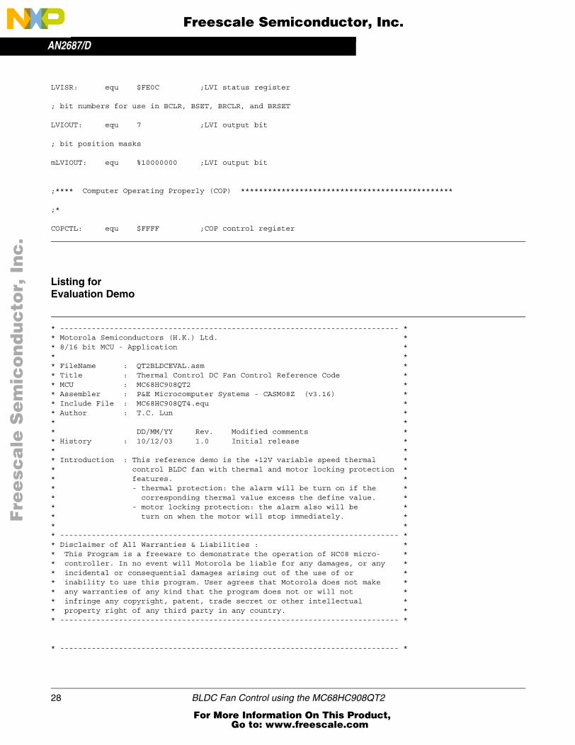
Listing for Evaluation Demo
* --------------------------------------------------------------------------- ** Motorola Semiconductors (H.K.) Ltd. ** 8/16 bit MCU - Application ** ** FileName : QT2BLDCEVAL.asm ** Title : Thermal Control DC Fan Control Reference Code ** MCU : MC68HC908QT2 ** Assembler : P&E Microcomputer Systems - CASM08Z (v3.16) ** Include File : MC68HC908QT4.equ ** Author : T.C. Lun ** ** DD/MM/YY Rev. Modified comments ** History : 10/12/03 1.0 Initial release ** ** Introduction : This reference demo is the +12V variable speed thermal ** control BLDC fan with thermal and motor locking protection ** features. ** - thermal protection: the alarm will be turn on if the ** corresponding thermal value excess the define value. ** - motor locking protection: the alarm also will be ** turn on when the motor will stop immediately. ** ** --------------------------------------------------------------------------- ** Disclaimer of All Warranties & Liabilities : ** This Program is a freeware to demonstrate the operation of HC08 micro- ** controller. In no event will Motorola be liable for any damages, or any ** incidental or consequential damages arising out of the use of or ** inability to use this program. User agrees that Motorola does not make ** any warranties of any kind that the program does not or will not ** infringe any copyright, patent, trade secret or other intellectual ** property right of any third party in any country. ** --------------------------------------------------------------------------- *
* --------------------------------------------------------------------------- *
Fre
esc
ale
Se
mic
on
du
cto
r, I
Freescale Semiconductor, Inc.
For More Information On This Product, Go to: www.freescale.com
nc
...

AN2687/DAPPENDIX B: CODE LISTINGS
BLDC Fan Control using the MC68HC908QT2 29
* Features and Pin Assigments MC68HC908QT2 ** --------------------------------------------------------------------------- ** Features:* . HC08 CPU core* . 3.2MHz Internal Bus Operation (using ICG, trimmed)* . $F800 ~ $FDFF ---- 1.5K bytes FLASH* . $0080 ~ $00FF ---- 128 bytes RAM* . 4-channel ADC* . 16-bit 2 channels Timer Interface Module(TIM)** 908QT2 Pin Assignment (8-PDIP package):* Pin Pin Name | Pin Pin Name* --- -------------------- | --- ----------------* 1 Vdd | 8 Vss* 2 AD3/PA5 - alarm(o/p) | 7 TCH0/PA0 - Hall(icap)* 3 AD2/PA4 - Out1(o/p) | 6 AD1/PA1 - Vset(adc)* 4 RST/PA3 - Out2(o/p) | 5 IRQ/PA2 - Hall(irq)* --- ------------------------------------------** Note:* - /VPP & RST# pins equipped with internal pullup R & Schmitt trig. i/p*
* --------------------------------------------------------------------------- ** Register and bit name definitions for MC68HC908QY4 and MC68HC908QT4 ** --------------------------------------------------------------------------- *$include "MC68HC908QT4.equ"
* --------------------------------------------------------------------------- ** Ram Allocation ** --------------------------------------------------------------------------- * ORG RamStart ; $0080
TMP ds 1 ; for delay routineTMP1 ds 1 ; for delay routine
Port_CTRL equ PTA ; Control PortDDR_CTRL equ DDRA ;
alarm equ 5 ; PTA5 drive alarmout1 equ 3 ; PTA3 drive L1out2 equ 4 ; PTA4 drive L2
Flag ds 1 ; motor control flagirq_Flag equ 0icap_Flag equ 1start_Flag equ 2alarm_Flag equ 3
Thermal_Limit equ $15 ; Thermal limit value (Refer to the table)PWM_Period_H equ $0F ; Define the PWM periodPWM_Period_L equ $FFDuty_Cycle_H equ $0E ; Define the duty cycle (i.e. need less thanDuty_Cycle_L equ $FF ; 15% turn on time to aviod damage of ; transducer
org FlashStart ; F800 for QT1/2 or QY1/2 $EE00 for QT4/QY4
Fre
esc
ale
Se
mic
on
du
cto
r, I
Freescale Semiconductor, Inc.
For More Information On This Product, Go to: www.freescale.com
nc
...

AN2687/D
30 BLDC Fan Control using the MC68HC908QT2
* --------------------------------------------------------------------------- ** Subroutine <Initialization : Configure Registers and Bus Clock> ** In : <nil> ** Out : <nil> ** Call : enable_int_clk ** --------------------------------------------------------------------------- *
START: SEI ldhx #$FF+1 ; initialize txs ; the stack pointer mov #%00111001,CONFIG1 ; disable COP,LVI disable, disable STOP, long COP rate mov #%01000000,CONFIG2 ; RST pin function disable, select int. oscillator, ; IRQ enable at PTA2 with internal pull-up BSET 2,INTSCR ; CLEAR IRQF jsr enable_int_clk ; enable ICG for device only
* --------------------------------------------------------------------------- ** Subroutine <Initialization : RAM> ** In : RamStart ** Out : <nil> ** Call : <nil> ** --------------------------------------------------------------------------- *
ClrRAM sta $ffff ; CLEAR COP ldhx #RamStart ; point to start of RAMClearRAM: clr ,x ; clear RAM location aix #1 ; advance pointer cphx #RamLast+1 ; done ? bne ClearRAM ; loop back if not
* --------------------------------------------------------------------------- ** Subroutine <Initialization : I/O, Timer, ADC> ** In : <nil> ** Out : <nil> ** Call : Init_TIM_ICAP ** --------------------------------------------------------------------------- *
* Init the I/Os clr PTA mov #%00111000,DDRA ; PTA3,PTA4,PTA5 as output ; PTA2 = input only pin* Initialize the Timer module JSR Init_TIM_ICAP ; timer init. with TCH0 as input capture ; rising edge trigger
* Initialize the ADC module MOV #$40,ADICLK ; ADC CLOCK = BUSCLOCK / 4 = 0.8MHz with ; 12.8MHz ICG MOV #$21,ADSCR ; Interrupt disable, Continous conversion, ; PTA1 = ADC1
* --------------------------------------------------------------------------- ** Subroutine <Main + Startup Phase> ** In : irq_Flag, icap_Flag ** Out : Start_Flag ** Call : Delay_100ms ** --------------------------------------------------------------------------- *
Fre
esc
ale
Se
mic
on
du
cto
r, I
Freescale Semiconductor, Inc.
For More Information On This Product, Go to: www.freescale.com
nc
...

AN2687/DAPPENDIX B: CODE LISTINGS
BLDC Fan Control using the MC68HC908QT2 31
Main CLR Flag ; Clear the flag NOP clraStartup bset start_Flag,Flag cli BSET out2,PTA ; on out2 (L2 off first) BCLR out1,PTA ; off out1Wait_icap brset icap_Flag,Flag,End_Start ; Check hall signal
jsr Delay_100ms ; Delay 100ms
brset icap_Flag,Flag,End_Start ; Check hall signal again clr PTA ; Motor should be halt, then stop motor sei ; mask interrupt to stop motorDead_Loop_1 bset Alarm,PTA ; Turn on alarm mov #10,TMP1 ; 1 second turn on timeTurn_On_Again_1 jsr Delay_100ms dec TMP1 lda TMP1 bne Turn_On_Again_1
bclr alarm,PTA ; Turn off alarm mov #10,TMP1 ; 1 second turn on timeTurn_On_Again_2 jsr Delay_100ms dec TMP1 lda TMP1 bne Turn_On_Again_2
bra Dead_Loop_1 ; Dead loop, need to re-start by POR
End_Start ; End of the motor start cycle
brset irq_Flag,Flag,No_Error ; Check Error brset icap_Flag,Flag,No_Error ; Check Error nop nop clr PTA ; Error occur, stop motor sei ; mask interrupt to stop motorDead_Loop_2 bset Alarm,PTA ; Turn on alarm mov #3,TMP1 ; 0.3 second turn on timeTurn_On_Again_3 jsr Delay_100ms dec TMP1 lda TMP1 bne Turn_On_Again_3
bclr Alarm,PTA ; Turn off alarm mov #3,TMP1 ; 0.3 second turn on time
Turn_On_Again_4
Fre
esc
ale
Se
mic
on
du
cto
r, I
Freescale Semiconductor, Inc.
For More Information On This Product, Go to: www.freescale.com
nc
...

AN2687/D
32 BLDC Fan Control using the MC68HC908QT2
jsr Delay_100ms dec TMP1 lda TMP1 bne Turn_On_Again_4
bra Dead_Loop_2 ; Dead loop, need to re-start by POR
No_Error bclr irq_FLag,Flag bclr icap_Flag,Flag bclr start_Flag,Flag
jsr Delay_100ms ; Delay 100ms
bra End_Start bra * ; For Checking only
* --------------------------------------------------------------------------- ** Subroutine <Enable external clock. For EM board> ** ICG Clock = 12.8MHz, Bus Clock = 12.8MHz/4 = 3.2MHz, 1 Cycle = 0.3125us ** In : <nil> ** Out : <nil> ** Call : <nil> ** --------------------------------------------------------------------------- *enable_ext_clock:
mov #18,$1E ; enable external crystal (external = $08)Delay1 deca ; Delay 4096 cycles bne Delay1 bset 1,$36 ; set ECGON bit nop brclr 0,$36,* ; check ECGST bit bset 4,$36 ; set this unknow bit rts
* --------------------------------------------------------------------------- ** Subroutine <Enable internal 3.2MHz clock. For EM board> ** ICG Clock = 12.8MHz, Bus Clock = 12.8MHz/4 = 3.2MHz, 1 Cycle = 0.3125us ** In : <nil> ** Out : <nil> ** Call : <nil> ** --------------------------------------------------------------------------- *en_int_3M2_clk:
mov #$20,$37 ; turn the ICG to generated 3.2MHz bus mov #$2E,$38 rts
* --------------------------------------------------------------------------- ** Subroutine <Initialize the Oscillator for internal clock> ** ICG Clock = 12.8MHz, Bus Clock = 12.8MHz/4 = 3.2MHz, 1 Cycle = 0.3125us ** In : <nil> ** Out : <nil> ** Call : <nil> ** --------------------------------------------------------------------------- *Enable_int_Clk:
mov #$00,OSCSTAT ; use internal clock only lda $FFC0 sta OSCTRIM ; use current trim value rts
Fre
esc
ale
Se
mic
on
du
cto
r, I
Freescale Semiconductor, Inc.
For More Information On This Product, Go to: www.freescale.com
nc
...

AN2687/DAPPENDIX B: CODE LISTINGS
BLDC Fan Control using the MC68HC908QT2 33
* --------------------------------------------------------------------------- ** Subroutine <100ms Delay> ** ICG Clock = 12.8MHz, Bus Clock = 12.8MHz/4 = 3.2MHz, 1 Cycle = 0.3125us ** ((2560+2+3)*128+2+3)*0.3125us = 102.6ms ** In : <nil> ** Out : <nil> ** Call : <nil> ** --------------------------------------------------------------------------- *Delay_100ms:
LDX #$7C ; [2] ; 20ms: X=#$19 or (#25) ; 100ms: X=#$7C or (#128) ; 200ms: X=#$FA or (#250)Delay_100ms_X
LDA #$FF ; [2]
Delay_100ms_A
sta $FFFF ; [4] clear COP nop ; [1] nop ; [1] nop ; [1] dbnza Delay_100ms_A ; [3] ;10*256=256 dbnzx Delay_100ms_X ; [3] rts ; [3]
* --------------------------------------------------------------------------- ** Subroutine <Configure TIMER module as Input Capture for channel 0 (PTA0)> ** In : <nil> ** Out : <nil> ** Call : <nil> ** --------------------------------------------------------------------------- *Init_TIM_ICAP: MOV #$30,TSC ; stop and reset the TIM counter, disable ; TOF interrupt, internal bus clock/1 mov #%01000100,TSC0 ; ch0 interrupt enable, TCH0 use as input ; capture rising edge trigger MOV #$00,TCH0H ; output low at TCH0 MOV #$00,TCH0L BCLR 5,TSC ; clear TSTOP, enable timer counter LDA TSC0 ; read TCH0 status and control register to ; clear CH0F flag bclr CH0F,TSC0 ; clear CH0F flag lda TSC ; clear TOF flag bclr TOF,TSC rts
* --------------------------------------------------------------------------- ** DMY_ISR - dummy Interrupt Service Routine (with no operation) ** In : <nil> ** Out : <nil> ** Call : <nil> ** --------------------------------------------------------------------------- *DMY_ISR: nop rti
Fre
esc
ale
Se
mic
on
du
cto
r, I
Freescale Semiconductor, Inc.
For More Information On This Product, Go to: www.freescale.com
nc
...

AN2687/D
34 BLDC Fan Control using the MC68HC908QT2
* --------------------------------------------------------------------------- ** TIM0_ISR - Timer Interrupt Service Routine ** In : Start_Flag ** Out : icap_Flag ** Call : Table Look up ** --------------------------------------------------------------------------- *TIM0_ISR: LDA TSC0 ; read TCH0 status and control register to bclr CH0F,TSC0 ; clear CH0F flag
brset start_Flag,Flag,Skip_icap ; Check motor in start up phase ? BCLR out2,PTA ; off out2 lda ADR ; read ADC value ldhx #$FD00 ; point to table page tax ; point to corresponding speed lda ,x ; Read the speed value to Acc
cmp #$15 ; Check corresponding thermal excess limit? bhi No_Icap_alarm ; Alarm if excess bset alarm,PTA ; Turn on alarm bra Icap_alarm
No_Icap_alarm
bclr alarm,PTA ; Turn off alarm if below thermal limit
Icap_alarm
cbeqa #0,No_IcapDelay ; if A=0, No dalayICAP_Delay mov #10,TMPICAP_Delay1 NOP NOP DBNZ TMP,ICAP_Delay1 DBNZA ICAP_DelayNo_IcapDelay
BSET out1,PTA ; on out1Skip_icap bclr start_Flag,Flag bset icap_Flag,Flag ; For checking rti
* --------------------------------------------------------------------- ** IRQ_ISR - IRQ Interrupt Service Routine ** In : Start_Flag ** Out : icap_Flag ** Call : Table Look up ** --------------------------------------------------------------------- *IRQ_ISR: NOP BSET 2,INTSCR ; CLEAR IRQF
brset start_Flag,Flag,Skip_irq ; Check motor in start up phase ? BCLR out1,PTA ; off out1 lda ADR ; read ADC value ldhx #$FD00 ; point to table page
Fre
esc
ale
Se
mic
on
du
cto
r, I
Freescale Semiconductor, Inc.
For More Information On This Product, Go to: www.freescale.com
nc
...

AN2687/DAPPENDIX B: CODE LISTINGS
BLDC Fan Control using the MC68HC908QT2 35
tax ; point to corresponding speed lda ,x ; Read the speed value to Acc
cmp #$15 ; Check corresponding thermal excess limit? bhi No_Irq_alarm ; alarm if excess bset alarm,PTA ; Turn on alarm bra Irq_alarm
No_Irq_alarm
bclr alarm,PTA ; Turn off alarm if below thermal limit
Irq_alarm
cbeqa #0,No_IrqDelay ; if A=0, No dalayIRQ_Delay mov #10,TMPIRQ_Delay1 NOP NOP DBNZ TMP,IRQ_Delay1 DBNZA IRQ_DelayNo_IrqDelay
BSET out2,PTA ; on out2Skip_irq bclr start_Flag,Flag bset irq_Flag,Flag ; For checking RTI
* --------------------------------------------------------------------------- ** Look Up Table - Map requirement speed to value of thermal sensor ** In : <nil> ** Out : <nil> ** Call : <nil> ** --------------------------------------------------------------------------- *; org $FD00 ; Table 1 (U sharp for test); This table is also used for QT2 BLDC Fan test only
; FCB $F0,$F1,$F2,$F3,$F4,$F5,$F6,$F7,$F8,$F9,$FA,$FB,$FC,$FD,$FE,$FF; FCB $E0,$E1,$E2,$E3,$E4,$E5,$E6,$E7,$E8,$E9,$EA,$EB,$EC,$ED,$EE,$EF; FCB $D0,$D1,$D2,$D3,$D4,$D5,$D6,$D7,$D8,$D9,$DA,$DB,$DC,$DD,$DE,$DF; FCB $C0,$C1,$C2,$C3,$C4,$C5,$C6,$C7,$C8,$C9,$CA,$CB,$CC,$CD,$CE,$CF; FCB $B0,$B1,$B2,$B3,$B4,$B5,$B6,$B7,$B8,$B9,$BA,$BB,$BC,$BD,$BE,$BF; FCB $A0,$A1,$A2,$A3,$A4,$A5,$A6,$A7,$A8,$A9,$AA,$AB,$AC,$AD,$AE,$AF; FCB $90,$91,$92,$93,$94,$95,$96,$97,$98,$99,$9A,$9B,$9C,$9D,$9E,$9F; FCB $80,$81,$82,$83,$84,$85,$86,$87,$88,$89,$8A,$8B,$8C,$8D,$8E,$8F; FCB $80,$81,$82,$83,$84,$85,$86,$87,$88,$89,$8A,$8B,$8C,$8D,$8E,$8F; FCB $90,$91,$92,$93,$94,$95,$96,$97,$98,$99,$9A,$9B,$9C,$9D,$9E,$9F; FCB $A0,$A1,$A2,$A3,$A4,$A5,$A6,$A7,$A8,$A9,$AA,$AB,$AC,$AD,$AE,$AF; FCB $B0,$B1,$B2,$B3,$B4,$B5,$B6,$B7,$B8,$B9,$BA,$BB,$BC,$BD,$BE,$BF; FCB $C0,$C1,$C2,$C3,$C4,$C5,$C6,$C7,$C8,$C9,$CA,$CB,$CC,$CD,$CE,$CF; FCB $D0,$D1,$D2,$D3,$D4,$D5,$D6,$D7,$D8,$D9,$DA,$DB,$DC,$DD,$DE,$DF; FCB $E0,$E1,$E2,$E3,$E4,$E5,$E6,$E7,$E8,$E9,$EA,$EB,$EC,$ED,$EE,$EF; FCB $F0,$F1,$F2,$F3,$F4,$F5,$F6,$F7,$F8,$F9,$FA,$FB,$FC,$FD,$FE,$FF
; org $FD00 ; Table 2 (Linear for VR); This table is also used for QT2 BLDC Fan evaluation type board with P6=VR control
; FCB $00,$01,$02,$03,$04,$05,$06,$07,$08,$09,$0A,$0B,$0C,$0D,$0E,$0F; FCB $10,$11,$12,$13,$14,$15,$16,$17,$18,$19,$1A,$1B,$1C,$1D,$1E,$1F
Fre
esc
ale
Se
mic
on
du
cto
r, I
Freescale Semiconductor, Inc.
For More Information On This Product, Go to: www.freescale.com
nc
...

AN2687/D
36 BLDC Fan Control using the MC68HC908QT2
; FCB $20,$21,$22,$23,$24,$25,$26,$27,$28,$29,$2A,$2B,$2C,$2D,$2E,$2F; FCB $30,$31,$32,$33,$34,$35,$36,$37,$38,$39,$3A,$3B,$3C,$3D,$3E,$3F; FCB $40,$41,$42,$43,$44,$45,$46,$47,$48,$49,$4A,$4B,$4C,$4D,$4E,$4F; FCB $50,$51,$52,$53,$54,$55,$56,$57,$58,$59,$5A,$5B,$5C,$5D,$5E,$5F; FCB $60,$61,$62,$63,$64,$65,$66,$67,$68,$69,$6A,$6B,$6C,$6D,$6E,$6F; FCB $70,$71,$72,$73,$74,$75,$76,$77,$78,$79,$7A,$7B,$7C,$7D,$7E,$7F; FCB $80,$81,$82,$83,$84,$85,$86,$87,$88,$89,$8A,$8B,$8C,$8D,$8E,$8F; FCB $90,$91,$92,$93,$94,$95,$96,$97,$98,$99,$9A,$9B,$9C,$9D,$9E,$9F; FCB $A0,$A1,$A2,$A3,$A4,$A5,$A6,$A7,$A8,$A9,$AA,$AB,$AC,$AD,$AE,$AF; FCB $B0,$B1,$B2,$B3,$B4,$B5,$B6,$B7,$B8,$B9,$BA,$BB,$BC,$BD,$BE,$BF; FCB $C0,$C1,$C2,$C3,$C4,$C5,$C6,$C7,$C8,$C9,$CA,$CB,$CC,$CD,$CE,$CF; FCB $D0,$D1,$D2,$D3,$D4,$D5,$D6,$D7,$D8,$D9,$DA,$DB,$DC,$DD,$DE,$DF; FCB $E0,$E1,$E2,$E3,$E4,$E5,$E6,$E7,$E8,$E9,$EA,$EB,$EC,$ED,$EE,$EF; FCB $F0,$F1,$F2,$F3,$F4,$F5,$F6,$F7,$F8,$F9,$FA,$FB,$FC,$FD,$FE,$FF
; org $FD00 ; Table 3 (20K@25 degree C NTC Thermal sensor); need to change the value of the pull up resistor R9
; FCB $00,$00,$00,$00,$00,$00,$00,$00,$00,$00,$00,$00,$00,$00,$00,$00; FCB $00,$00,$00,$00,$00,$00,$00,$00,$00,$00,$00,$00,$00,$00,$00,$00; FCB $00,$00,$00,$00,$00,$00,$00,$00,$00,$00,$00,$00,$00,$00,$00,$00; FCB $00,$00,$00,$00,$00,$00,$00,$03,$06,$09,$0C,$0F,$12,$15,$17,$19; FCB $1B,$1E,$21,$24,$27,$2A,$2C,$2E,$30,$32,$34,$36,$39,$3C,$3F,$42; FCB $44,$46,$48,$4A,$4C,$4E,$50,$52,$54,$56,$58,$5A,$5C,$5E,$61,$63; FCB $65,$67,$69,$6B,$6D,$6F,$71,$73,$75,$77,$79,$7B,$7D,$7E,$80,$81; FCB $83,$84,$86,$87,$89,$8A,$8C,$8E,$91,$93,$95,$97,$99,$9B,$9D,$9F; FCB $A1,$A3,$A5,$A7,$A9,$AB,$AC,$AE,$AF,$B1,$B2,$B4,$B5,$B7,$B8,$BA; FCB $BB,$BD,$BF,$C1,$C3,$C5,$C6,$C7,$C8,$C9,$CA,$CB,$CC,$CD,$CE,$CF; FCB $D0,$D1,$D2,$D3,$D4,$D5,$D6,$D7,$D8,$D9,$DA,$DB,$DC,$DD,$DE,$DF; FCB $E0,$E1,$E2,$E3,$E4,$E5,$E6,$E7,$E8,$E9,$EA,$EB,$EC,$ED,$EE,$EF; FCB $F0,$F1,$F3,$F5,$F7,$F8,$F9,$FA,$FB,$FC,$FD,$FE,$FF,$FF,$FF,$FF; FCB $FF,$FF,$FF,$FF,$FF,$FF,$FF,$FF,$FF,$FF,$FF,$FF,$FF,$FF,$FF,$FF; FCB $FF,$FF,$FF,$FF,$FF,$FF,$FF,$FF,$FF,$FF,$FF,$FF,$FF,$FF,$FF,$FF; FCB $FF,$FF,$FF,$FF,$FF,$FF,$FF,$FF,$FF,$FF,$FF,$FF,$FF,$FF,$FF,$FF
org $FD00 ; Table 4 (10K@25 degree C NTC Thermal sensor); This table is used for the QT2 BLDC Fan demo type board and R9=7.5K; This table is also used for QT2 BLDC Fan evaluation type board with P6=thermal control
FCB $00,$00,$00,$00,$00,$00,$00,$00,$00,$00,$00,$00,$00,$00,$00,$00 FCB $00,$00,$00,$00,$00,$00,$00,$00,$00,$00,$00,$00,$00,$00,$00,$00 FCB $00,$00,$00,$00,$00,$00,$00,$00,$00,$00,$00,$00,$00,$00,$00,$00 FCB $00,$00,$00,$00,$00,$00,$00,$01,$02,$03,$04,$05,$06,$07,$0A,$0D FCB $10,$13,$16,$19,$1C,$1F,$21,$23,$26,$29,$2C,$2F,$32,$35,$38,$3A FCB $3D,$3F,$42,$44,$47,$49,$4C,$4E,$51,$54,$56,$59,$5B,$5E,$60,$63 FCB $65,$68,$6A,$6C,$6E,$70,$72,$74,$76,$78,$7A,$7D,$80,$82,$84,$86 FCB $88,$8B,$8E,$90,$92,$94,$96,$98,$9A,$9C,$9E,$A0,$A2,$A4,$A6,$A8 FCB $AA,$AC,$AE,$B1,$B3,$B5,$B7,$B9,$BB,$BD,$BF,$C1,$C3,$C5,$C7,$C9 FCB $CB,$CD,$CE,$D0,$D2,$D4,$D6,$D8,$D9,$DA,$DB,$DC,$DD,$DE,$DF,$E0 FCB $E1,$E2,$E2,$E3,$E3,$E4,$E4,$E5,$E5,$E6,$E6,$E7,$E7,$E8,$E8,$E9 FCB $E9,$EA,$EA,$EB,$EB,$EC,$EC,$ED,$EE,$EF,$F0,$F1,$F2,$F3,$F4,$F5 FCB $F6,$F6,$F7,$F8,$F9,$FA,$FB,$FC,$FD,$FE,$FF,$FF,$FF,$FF,$FF,$FF FCB $FF,$FF,$FF,$FF,$FF,$FF,$FF,$FF,$FF,$FF,$FF,$FF,$FF,$FF,$FF,$FF FCB $FF,$FF,$FF,$FF,$FF,$FF,$FF,$FF,$FF,$FF,$FF,$FF,$FF,$FF,$FF,$FF FCB $FF,$FF,$FF,$FF,$FF,$FF,$FF,$FF,$FF,$FF,$FF,$FF,$FF,$FF,$FF,$FF
* --------------------------------------------------------------------------- ** User Vectors - Location of User Vectors ** In : <nil> ** Out : <nil> ** Call : <nil> *
Fre
esc
ale
Se
mic
on
du
cto
r, I
Freescale Semiconductor, Inc.
For More Information On This Product, Go to: www.freescale.com
nc
...

AN2687/DAPPENDIX B: CODE LISTINGS
BLDC Fan Control using the MC68HC908QT2 37
* --------------------------------------------------------------------------- * org $FFE0ADCIRQ DW DMY_ISR
org $FFDEKBIRQ DW DMY_ISR
org $FFF2TOFIRQ DW DMY_ISRTIMCH1IRQ DW DMY_ISRTIMCH0IRQ DW TIM0_ISR
org $FFFAEXT_IRQ DW IRQ_ISRSWI_IRQ DW DMY_ISRRESET DW START
Listing for Reference Demo
* --------------------------------------------------------------------------- ** Motorola Semiconductors (H.K.) Ltd. ** 8/16 bit MCU - Application ** ** FileName : QT2BLDCDEMO.asm ** Title : Thermal Control DC Fan Control Reference Code ** MCU : MC68HC908QT2 ** Assembler : P&E Microcomputer Systems - CASM08Z (v3.16) ** Include File : MC68HC908QT4.equ ** Author : T.C. Lun ** ** DD/MM/YY Rev. Modified comments ** History : 10/12/03 1.0 Initial release ** ** Introduction : This reference demo is the +12V variable speed thermal ** control BLDC fan with thermal and motor locking protection ** features. ** - thermal protection: the alarm will be turn on if the ** corresponding thermal value excess the define value. ** - motor locking protection: the alarm also will be ** turn on when the motor will stop immediately. ** ** --------------------------------------------------------------------------- ** Disclaimer of All Warranties & Liabilities : ** This Program is a freeware to demonstrate the operation of HC08 micro- ** controller. In no event will Motorola be liable for any damages, or any ** incidental or consequential damages arising out of the use of or ** inability to use this program. User agrees that Motorola does not make ** any warranties of any kind that the program does not or will not ** infringe any copyright, patent, trade secret or other intellectual ** property right of any third party in any country. ** --------------------------------------------------------------------------- *
* --------------------------------------------------------------------------- *
Fre
esc
ale
Se
mic
on
du
cto
r, I
Freescale Semiconductor, Inc.
For More Information On This Product, Go to: www.freescale.com
nc
...

AN2687/D
38 BLDC Fan Control using the MC68HC908QT2
* Features and Pin Assigments MC68HC908QT2 ** --------------------------------------------------------------------------- ** Features:* . HC08 CPU core* . 3.2MHz Internal Bus Operation (using ICG, trimmed)* . $F800 ~ $FDFF ---- 1.5K bytes FLASH* . $0080 ~ $00FF ---- 128 bytes RAM* . 4-channel ADC* . 16-bit 2 channels Timer Interface Module(TIM)** 908QT2 Pin Assignment (8-PDIP package):* Pin Pin Name | Pin Pin Name* --- -------------------- | --- ----------------* 1 Vdd | 8 Vss* 2 AD3/PA5 - Vset(adc) | 7 TCH0/PA0 - Hall(icap)* 3 AD2/PA4 - Out2(o/p) | 6 AD1/PA1 - alarm(o/p)* 4 RST/PA3 - Out1(o/p) | 5 IRQ/PA2 - Hall(irq)* --- ------------------------------------------** Note:* - /VPP & RST# pins equipped with internal pullup R & Schmitt trig. i/p*
* --------------------------------------------------------------------------- ** Register and bit name definitions for MC68HC908QY4 and MC68HC908QT4 ** --------------------------------------------------------------------------- *$include "MC68HC908QT4.equ"
* --------------------------------------------------------------------------- ** Ram Allocation ** --------------------------------------------------------------------------- * ORG RamStart ; $0080
TMP ds 1 ; for delay routineTMP1 ds 1 ; for delay routine
Port_CTRL equ PTA ; Control PortDDR_CTRL equ DDRA ;
alarm equ 1 ; PTA1 drive alarmout1 equ 3 ; PTA3 drive L1out2 equ 4 ; PTA4 drive L2
Flag ds 1 ; motor control flagirq_Flag equ 0icap_Flag equ 1start_Flag equ 2alarm_Flag equ 3
Thermal_Limit equ $15 ; Thermal limit value (Refer to the table)PWM_Period_H equ $0F ; Define the PWM periodPWM_Period_L equ $FFDuty_Cycle_H equ $0E ; Define the duty cycle (i.e. need less thanDuty_Cycle_L equ $FF ; 15% turn on time to aviod damage of ; transducer
org FlashStart ; F800 for QT1/2 or QY1/2 $EE00 for QT4/QY4
* --------------------------------------------------------------------------- *
Fre
esc
ale
Se
mic
on
du
cto
r, I
Freescale Semiconductor, Inc.
For More Information On This Product, Go to: www.freescale.com
nc
...

AN2687/DAPPENDIX B: CODE LISTINGS
BLDC Fan Control using the MC68HC908QT2 39
* Subroutine <Initialization : Configure Registers and Bus Clock> ** In : <nil> ** Out : <nil> ** Call : enable_int_clk ** --------------------------------------------------------------------------- *
START: SEI ldhx #$FF+1 ; initialize txs ; the stack pointer mov #%00111001,CONFIG1 ; disable COP,LVI disable, disable STOP, long COP rate mov #%01000000,CONFIG2 ; RST pin function disable, select int. oscillator, ; IRQ enable at PTA2 with internal pull-up BSET 2,INTSCR ; CLEAR IRQF jsr enable_int_clk ; enable ICG for device only
* --------------------------------------------------------------------------- ** Subroutine <Initialization : RAM> ** In : RamStart ** Out : <nil> ** Call : <nil> ** --------------------------------------------------------------------------- *
ClrRAM sta $ffff ; CLEAR COP ldhx #RamStart ; point to start of RAMClearRAM: clr ,x ; clear RAM location aix #1 ; advance pointer cphx #RamLast+1 ; done ? bne ClearRAM ; loop back if not
* --------------------------------------------------------------------------- ** Subroutine <Initialization : I/O, Timer, ADC> ** In : <nil> ** Out : <nil> ** Call : Init_TIM_ICAP ** --------------------------------------------------------------------------- *
* Init the I/Os clr PTA mov #%00011010,DDRA ; PTA1,PTA3,PTA4 as output ; PTA2 = input only pin* Initialize the Timer module JSR Init_TIM_ICAP ; timer init. with TCH0 as input capture ; rising edge trigger
* Initialize the ADC module MOV #$40,ADICLK ; ADC CLOCK = BUSCLOCK / 4 = 0.8MHz with ; 12.8MHz ICG MOV #$23,ADSCR ; Interrupt disable, Continous conversion, ; PTA5 = ADC3
* --------------------------------------------------------------------------- ** Subroutine <Main + Startup Phase> ** In : irq_Flag, icap_Flag ** Out : Start_Flag ** Call : Delay_100ms, Delay_Xms ** --------------------------------------------------------------------------- *
Main
Fre
esc
ale
Se
mic
on
du
cto
r, I
Freescale Semiconductor, Inc.
For More Information On This Product, Go to: www.freescale.com
nc
...

AN2687/D
40 BLDC Fan Control using the MC68HC908QT2
CLR Flag ; Clear the flag NOP clraStartup bset start_Flag,Flag cli BSET out2,PTA ; on out2 (L2 off first) BCLR out1,PTA ; off out1Wait_icap brset icap_Flag,Flag,End_Start ; Check hall signal
jsr Delay_100ms ; Delay 100ms
brset icap_Flag,Flag,End_Start ; Check hall signal again clr PTA ; Motor should be halt, then stop motor sei ; mask interrupt to stop motorDead_Loop_1 bset alarm,PTA ; Turn on alarm
jsr Delay_Xms bclr alarm,PTA ;
jsr Delay_Yms bra Dead_Loop_1 ; Dead loop, need to re-start by POR
End_Start ; End of the motor start cycle
brset irq_Flag,Flag,No_Error ; Check Error brset icap_Flag,Flag,No_Error ; Check Error nop nop clr PTA ; Error occur, stop motor sei ; mask interrupt to stop motorDead_Loop_2 bset alarm,PTA ; Turn on alarm
jsr Delay_Xms bclr alarm,PTA ;
jsr Delay_Yms bra Dead_Loop_2 ; Dead loop, need to re-start by POR
No_Error bclr irq_FLag,Flag bclr icap_Flag,Flag bclr start_Flag,Flag
brclr alarm_Flag,Flag,alarm_Off mov #%01011110,TSC1 ; ch1 interrupt enable, TCH1 use as output ; compare set output on compare ; alarm On bra No_Offalarm_Off clr TSC1 ; alarm OffNo_Off
jsr Delay_100ms ; Delay 100ms
Fre
esc
ale
Se
mic
on
du
cto
r, I
Freescale Semiconductor, Inc.
For More Information On This Product, Go to: www.freescale.com
nc
...

AN2687/DAPPENDIX B: CODE LISTINGS
BLDC Fan Control using the MC68HC908QT2 41
bra End_Start bra * ; For Checking only
* --------------------------------------------------------------------------- ** Subroutine <Enable external clock. For EM board> ** ICG Clock = 12.8MHz, Bus Clock = 12.8MHz/4 = 3.2MHz, 1 Cycle = 0.3125us ** In : <nil> ** Out : <nil> ** Call : <nil> ** --------------------------------------------------------------------------- *enable_ext_clock:
mov #18,$1E ; enable external crystal (external = $08)Delay1 deca ; Delay 4096 cycles bne Delay1 bset 1,$36 ; set ECGON bit nop brclr 0,$36,* ; check ECGST bit bset 4,$36 ; set this unknow bit rts
* --------------------------------------------------------------------------- ** Subroutine <Enable internal 3.2MHz clock. For EM board> ** ICG Clock = 12.8MHz, Bus Clock = 12.8MHz/4 = 3.2MHz, 1 Cycle = 0.3125us ** In : <nil> ** Out : <nil> ** Call : <nil> ** --------------------------------------------------------------------------- *en_int_3M2_clk:
mov #$20,$37 ; turn the ICG to generated 3.2MHz bus mov #$2E,$38 rts
* --------------------------------------------------------------------------- ** Subroutine <Initialize the Oscillator for internal clock> ** ICG Clock = 12.8MHz, Bus Clock = 12.8MHz/4 = 3.2MHz, 1 Cycle = 0.3125us ** In : <nil> ** Out : <nil> ** Call : <nil> ** --------------------------------------------------------------------------- *Enable_int_Clk:
mov #$00,OSCSTAT ; use internal clock only lda $FFC0 sta OSCTRIM ; use current trim value rts
* --------------------------------------------------------------------------- ** Subroutine <Yms Delay> ** ICG Clock = 12.8MHz, Bus Clock = 12.8MHz/4 = 3.2MHz, 1 Cycle = 0.3125us ** (((2560/2)+2+3)*6+2+3))*0.3125us = 2.41ms ** In : <nil> ** Out : <nil> ** Call : <nil> ** --------------------------------------------------------------------------- *Delay_Yms:
LDX #$06 ; [2]
Fre
esc
ale
Se
mic
on
du
cto
r, I
Freescale Semiconductor, Inc.
For More Information On This Product, Go to: www.freescale.com
nc
...

AN2687/D
42 BLDC Fan Control using the MC68HC908QT2
Delay_Yms_X
LDA #$80 ; [2]
Delay_Yms_A
sta $FFFF ; [4] clear COP nop ; [1] nop ; [1] nop ; [1] dbnza Delay_Yms_A ; [3] ;10*256=256 dbnzx Delay_Yms_X ; [3] rts ; [3]
* --------------------------------------------------------------------------- ** Subroutine <Xms Delay> ** ICG Clock = 12.8MHz, Bus Clock = 12.8MHz/4 = 3.2MHz, 1 Cycle = 0.3125us ** (((2560/2)+2+3))*1+2+3))*0.3125us = 0.4ms ** In : <nil> ** Out : <nil> ** Call : <nil> ** --------------------------------------------------------------------------- *Delay_Xms:
LDX #$01 ; [2]
Delay_Xms_X
LDA #$80 ; [2]
Delay_Xms_A
sta $FFFF ; [4] clear COP nop ; [1] nop ; [1] nop ; [1] dbnza Delay_Xms_A ; [3] ;10*256=256 dbnzx Delay_Xms_X ; [3] rts ; [3]
* --------------------------------------------------------------------------- ** Subroutine <100ms Delay> ** ICG Clock = 12.8MHz, Bus Clock = 12.8MHz/4 = 3.2MHz, 1 Cycle = 0.3125us ** ((2560+2+3)*128+2+3)*0.3125us = 102.6ms ** In : <nil> ** Out : <nil> ** Call : <nil> ** --------------------------------------------------------------------------- *Delay_100ms:
LDX #$7C ; [2] ; 20ms: X=#$19 or (#25) ; 100ms: X=#$7C or (#128) ; 200ms: X=#$FA or (#250)
Delay_100ms_X
LDA #$FF ; [2]
Fre
esc
ale
Se
mic
on
du
cto
r, I
Freescale Semiconductor, Inc.
For More Information On This Product, Go to: www.freescale.com
nc
...

AN2687/DAPPENDIX B: CODE LISTINGS
BLDC Fan Control using the MC68HC908QT2 43
Delay_100ms_A
sta $FFFF ; [4] clear COP nop ; [1] nop ; [1] nop ; [1] dbnza Delay_100ms_A ; [3] ;10*256=256 dbnzx Delay_100ms_X ; [3] rts ; [3]
* --------------------------------------------------------------------------- ** Subroutine <Configure TIMER module as Input Capture for channel 0 (PTA0)> ** In : <nil> ** Out : <nil> ** Call : <nil> ** --------------------------------------------------------------------------- *Init_TIM_ICAP: MOV #$70,TSC ; stop and reset the TIM counter, enable ; TOF interrupt, internal bus clock/1 mov #%01000100,TSC0 ; ch0 interrupt enable, TCH0 use as input ; capture rising edge trigger ; TOF interrupt, internal bus clock/1
MOV #PWM_Period_H,TMODH; write overflow value to modulo registers MOV #PWM_Period_L,TMODL MOV #Duty_Cycle_H,TCH1H; write output compare value MOV #Duty_Cycle_L,TCH1L MOV #$00,TCH0H ; TCH0 MOV #$00,TCH0L BCLR 5,TSC ; clear TSTOP, enable timer counter LDA TSC0 ; read TCH0 status and control register to ; clear CH0F flag bclr CH0F,TSC0 ; clear CH0F flag LDA TSC1 ; read TCH1 status and control register to ; clear CH1F flag bclr CH1F,TSC0 ; clear CH1F flag lda TSC ; clear TOF flag bclr TOF,TSC rts* --------------------------------------------------------------------------- ** DMY_ISR - dummy Interrupt Service Routine (with no operation) ** In : <nil> ** Out : <nil> ** Call : <nil> ** --------------------------------------------------------------------------- *DMY_ISR: nop rti
* --------------------------------------------------------------------------- ** TOF_ISR - Timer Overflow Interrupt Service Routine ** In : <nil> ** Out : <nil> ** Call : <nil> ** --------------------------------------------------------------------------- *TOF_ISR: lda TSC ; clear TOF flag bclr TOF,TSC
rti
Fre
esc
ale
Se
mic
on
du
cto
r, I
Freescale Semiconductor, Inc.
For More Information On This Product, Go to: www.freescale.com
nc
...

AN2687/D
44 BLDC Fan Control using the MC68HC908QT2
* --------------------------------------------------------------------------- ** TIM1_ISR - Timer1 Interrupt Service Routine (Output compare) ** In : <nil> ** Out : <nil> ** Call : <nil> ** --------------------------------------------------------------------------- *TIM1_ISR:
LDA TSC1 ; read TCH1 status and control register to bclr CH1F,TSC1 ; clear CH1F flag
rti
* --------------------------------------------------------------------------- ** TIM0_ISR - Timer0 Interrupt Service Routine (Input capture) ** In : Start_Flag ** Out : icap_Flag ** Call : Table Look up ** --------------------------------------------------------------------------- *TIM0_ISR: LDA TSC0 ; read TCH0 status and control register to bclr CH0F,TSC0 ; clear CH0F flag
brset start_Flag,Flag,Skip_icap ; Check motor in start up phase ? BCLR out2,PTA ; off out2 lda ADR ; read ADC value ldhx #$FD00 ; point to table page tax ; point to corresponding speed lda ,x ; Read the speed value to Acc
cmp #Thermal_Limit ; Check corresponding thermal excess limit? bhi No_Icap_alarm ; alarm if excess
bset alarm_Flag,Flag
bra Icap_alarm
No_Icap_alarm
bclr alarm_Flag,Flag
Icap_alarm
cbeqa #0,No_IcapDelay ; if A=0, No dalayICAP_Delay mov #10,TMPICAP_Delay1 NOP NOP DBNZ TMP,ICAP_Delay1 DBNZA ICAP_DelayNo_IcapDelay
BSET out1,PTA ; on out1Skip_icap bclr start_Flag,Flag bset icap_Flag,Flag ; For checking rti
Fre
esc
ale
Se
mic
on
du
cto
r, I
Freescale Semiconductor, Inc.
For More Information On This Product, Go to: www.freescale.com
nc
...

AN2687/DAPPENDIX B: CODE LISTINGS
BLDC Fan Control using the MC68HC908QT2 45
* --------------------------------------------------------------------- ** IRQ_ISR - IRQ Interrupt Service Routine ** In : Start_Flag ** Out : icap_Flag ** Call : Table Look up ** --------------------------------------------------------------------- *IRQ_ISR: NOP BSET 2,INTSCR ; CLEAR IRQF
brset start_Flag,Flag,Skip_irq ; Check motor in start up phase ? BCLR out1,PTA ; off out1 lda ADR ; read ADC value ldhx #$FD00 ; point to table page tax ; point to corresponding speed lda ,x ; Read the speed value to Acc
cmp #Thermal_Limit ; Check corresponding thermal excess limit? bhi No_Irq_alarm ; alarm if excess bset alarm_Flag,Flag
bra Irq_alarm
No_Irq_alarm
bclr alarm_Flag,Flag ; clear alarm flag
Irq_alarm
cbeqa #0,No_IrqDelay ; if A=0, No dalayIRQ_Delay mov #10,TMPIRQ_Delay1 NOP NOP DBNZ TMP,IRQ_Delay1 DBNZA IRQ_DelayNo_IrqDelay
BSET out2,PTA ; on out2Skip_irq bclr start_Flag,Flag bset irq_Flag,Flag ; For checking RTI
* --------------------------------------------------------------------------- ** Look Up Table - Map requirement speed to value of thermal sensor ** In : <nil> ** Out : <nil> ** Call : <nil> ** --------------------------------------------------------------------------- *; org $FD00 ; Table 1 (U sharp for test); This table is also used for QT2 BLDC Fan test only
; FCB $F0,$F1,$F2,$F3,$F4,$F5,$F6,$F7,$F8,$F9,$FA,$FB,$FC,$FD,$FE,$FF; FCB $E0,$E1,$E2,$E3,$E4,$E5,$E6,$E7,$E8,$E9,$EA,$EB,$EC,$ED,$EE,$EF; FCB $D0,$D1,$D2,$D3,$D4,$D5,$D6,$D7,$D8,$D9,$DA,$DB,$DC,$DD,$DE,$DF; FCB $C0,$C1,$C2,$C3,$C4,$C5,$C6,$C7,$C8,$C9,$CA,$CB,$CC,$CD,$CE,$CF; FCB $B0,$B1,$B2,$B3,$B4,$B5,$B6,$B7,$B8,$B9,$BA,$BB,$BC,$BD,$BE,$BF; FCB $A0,$A1,$A2,$A3,$A4,$A5,$A6,$A7,$A8,$A9,$AA,$AB,$AC,$AD,$AE,$AF
Fre
esc
ale
Se
mic
on
du
cto
r, I
Freescale Semiconductor, Inc.
For More Information On This Product, Go to: www.freescale.com
nc
...

AN2687/D
46 BLDC Fan Control using the MC68HC908QT2
; FCB $90,$91,$92,$93,$94,$95,$96,$97,$98,$99,$9A,$9B,$9C,$9D,$9E,$9F; FCB $80,$81,$82,$83,$84,$85,$86,$87,$88,$89,$8A,$8B,$8C,$8D,$8E,$8F; FCB $80,$81,$82,$83,$84,$85,$86,$87,$88,$89,$8A,$8B,$8C,$8D,$8E,$8F; FCB $90,$91,$92,$93,$94,$95,$96,$97,$98,$99,$9A,$9B,$9C,$9D,$9E,$9F; FCB $A0,$A1,$A2,$A3,$A4,$A5,$A6,$A7,$A8,$A9,$AA,$AB,$AC,$AD,$AE,$AF; FCB $B0,$B1,$B2,$B3,$B4,$B5,$B6,$B7,$B8,$B9,$BA,$BB,$BC,$BD,$BE,$BF; FCB $C0,$C1,$C2,$C3,$C4,$C5,$C6,$C7,$C8,$C9,$CA,$CB,$CC,$CD,$CE,$CF; FCB $D0,$D1,$D2,$D3,$D4,$D5,$D6,$D7,$D8,$D9,$DA,$DB,$DC,$DD,$DE,$DF; FCB $E0,$E1,$E2,$E3,$E4,$E5,$E6,$E7,$E8,$E9,$EA,$EB,$EC,$ED,$EE,$EF; FCB $F0,$F1,$F2,$F3,$F4,$F5,$F6,$F7,$F8,$F9,$FA,$FB,$FC,$FD,$FE,$FF
; org $FD00 ; Table 2 (Linear for VR); This table is also used for QT2 BLDC Fan evaluation type board with P6=VR control
; FCB $00,$01,$02,$03,$04,$05,$06,$07,$08,$09,$0A,$0B,$0C,$0D,$0E,$0F; FCB $10,$11,$12,$13,$14,$15,$16,$17,$18,$19,$1A,$1B,$1C,$1D,$1E,$1F; FCB $20,$21,$22,$23,$24,$25,$26,$27,$28,$29,$2A,$2B,$2C,$2D,$2E,$2F; FCB $30,$31,$32,$33,$34,$35,$36,$37,$38,$39,$3A,$3B,$3C,$3D,$3E,$3F; FCB $40,$41,$42,$43,$44,$45,$46,$47,$48,$49,$4A,$4B,$4C,$4D,$4E,$4F; FCB $50,$51,$52,$53,$54,$55,$56,$57,$58,$59,$5A,$5B,$5C,$5D,$5E,$5F; FCB $60,$61,$62,$63,$64,$65,$66,$67,$68,$69,$6A,$6B,$6C,$6D,$6E,$6F; FCB $70,$71,$72,$73,$74,$75,$76,$77,$78,$79,$7A,$7B,$7C,$7D,$7E,$7F; FCB $80,$81,$82,$83,$84,$85,$86,$87,$88,$89,$8A,$8B,$8C,$8D,$8E,$8F; FCB $90,$91,$92,$93,$94,$95,$96,$97,$98,$99,$9A,$9B,$9C,$9D,$9E,$9F; FCB $A0,$A1,$A2,$A3,$A4,$A5,$A6,$A7,$A8,$A9,$AA,$AB,$AC,$AD,$AE,$AF; FCB $B0,$B1,$B2,$B3,$B4,$B5,$B6,$B7,$B8,$B9,$BA,$BB,$BC,$BD,$BE,$BF; FCB $C0,$C1,$C2,$C3,$C4,$C5,$C6,$C7,$C8,$C9,$CA,$CB,$CC,$CD,$CE,$CF; FCB $D0,$D1,$D2,$D3,$D4,$D5,$D6,$D7,$D8,$D9,$DA,$DB,$DC,$DD,$DE,$DF; FCB $E0,$E1,$E2,$E3,$E4,$E5,$E6,$E7,$E8,$E9,$EA,$EB,$EC,$ED,$EE,$EF; FCB $F0,$F1,$F2,$F3,$F4,$F5,$F6,$F7,$F8,$F9,$FA,$FB,$FC,$FD,$FE,$FF
; org $FD00 ; Table 3 (20K@25 degree C NTC Thermal sensor); need to change the value of the pull up resistor R9
; FCB $00,$00,$00,$00,$00,$00,$00,$00,$00,$00,$00,$00,$00,$00,$00,$00; FCB $00,$00,$00,$00,$00,$00,$00,$00,$00,$00,$00,$00,$00,$00,$00,$00; FCB $00,$00,$00,$00,$00,$00,$00,$00,$00,$00,$00,$00,$00,$00,$00,$00; FCB $00,$00,$00,$00,$00,$00,$00,$03,$06,$09,$0C,$0F,$12,$15,$17,$19; FCB $1B,$1E,$21,$24,$27,$2A,$2C,$2E,$30,$32,$34,$36,$39,$3C,$3F,$42; FCB $44,$46,$48,$4A,$4C,$4E,$50,$52,$54,$56,$58,$5A,$5C,$5E,$61,$63; FCB $65,$67,$69,$6B,$6D,$6F,$71,$73,$75,$77,$79,$7B,$7D,$7E,$80,$81; FCB $83,$84,$86,$87,$89,$8A,$8C,$8E,$91,$93,$95,$97,$99,$9B,$9D,$9F; FCB $A1,$A3,$A5,$A7,$A9,$AB,$AC,$AE,$AF,$B1,$B2,$B4,$B5,$B7,$B8,$BA; FCB $BB,$BD,$BF,$C1,$C3,$C5,$C6,$C7,$C8,$C9,$CA,$CB,$CC,$CD,$CE,$CF; FCB $D0,$D1,$D2,$D3,$D4,$D5,$D6,$D7,$D8,$D9,$DA,$DB,$DC,$DD,$DE,$DF; FCB $E0,$E1,$E2,$E3,$E4,$E5,$E6,$E7,$E8,$E9,$EA,$EB,$EC,$ED,$EE,$EF; FCB $F0,$F1,$F3,$F5,$F7,$F8,$F9,$FA,$FB,$FC,$FD,$FE,$FF,$FF,$FF,$FF; FCB $FF,$FF,$FF,$FF,$FF,$FF,$FF,$FF,$FF,$FF,$FF,$FF,$FF,$FF,$FF,$FF; FCB $FF,$FF,$FF,$FF,$FF,$FF,$FF,$FF,$FF,$FF,$FF,$FF,$FF,$FF,$FF,$FF; FCB $FF,$FF,$FF,$FF,$FF,$FF,$FF,$FF,$FF,$FF,$FF,$FF,$FF,$FF,$FF,$FF
org $FD00 ; Table 4 (10K@25 degree C NTC Thermal sensor); This table is used for the QT2 BLDC Fan demo type board and R9=7.5K; This table is also used for QT2 BLDC Fan evaluation type board with P6=thermal control
FCB $00,$00,$00,$00,$00,$00,$00,$00,$00,$00,$00,$00,$00,$00,$00,$00 FCB $00,$00,$00,$00,$00,$00,$00,$00,$00,$00,$00,$00,$00,$00,$00,$00 FCB $00,$00,$00,$00,$00,$00,$00,$00,$00,$00,$00,$00,$00,$00,$00,$00 FCB $00,$00,$00,$00,$00,$00,$00,$01,$02,$03,$04,$05,$06,$07,$0A,$0D FCB $10,$13,$16,$19,$1C,$1F,$21,$23,$26,$29,$2C,$2F,$32,$35,$38,$3A
Fre
esc
ale
Se
mic
on
du
cto
r, I
Freescale Semiconductor, Inc.
For More Information On This Product, Go to: www.freescale.com
nc
...

AN2687/DAPPENDIX B: CODE LISTINGS
BLDC Fan Control using the MC68HC908QT2 47
FCB $3D,$3F,$42,$44,$47,$49,$4C,$4E,$51,$54,$56,$59,$5B,$5E,$60,$63 FCB $65,$68,$6A,$6C,$6E,$70,$72,$74,$76,$78,$7A,$7D,$80,$82,$84,$86 FCB $88,$8B,$8E,$90,$92,$94,$96,$98,$9A,$9C,$9E,$A0,$A2,$A4,$A6,$A8 FCB $AA,$AC,$AE,$B1,$B3,$B5,$B7,$B9,$BB,$BD,$BF,$C1,$C3,$C5,$C7,$C9 FCB $CB,$CD,$CE,$D0,$D2,$D4,$D6,$D8,$D9,$DA,$DB,$DC,$DD,$DE,$DF,$E0 FCB $E1,$E2,$E2,$E3,$E3,$E4,$E4,$E5,$E5,$E6,$E6,$E7,$E7,$E8,$E8,$E9 FCB $E9,$EA,$EA,$EB,$EB,$EC,$EC,$ED,$EE,$EF,$F0,$F1,$F2,$F3,$F4,$F5 FCB $F6,$F6,$F7,$F8,$F9,$FA,$FB,$FC,$FD,$FE,$FF,$FF,$FF,$FF,$FF,$FF FCB $FF,$FF,$FF,$FF,$FF,$FF,$FF,$FF,$FF,$FF,$FF,$FF,$FF,$FF,$FF,$FF FCB $FF,$FF,$FF,$FF,$FF,$FF,$FF,$FF,$FF,$FF,$FF,$FF,$FF,$FF,$FF,$FF FCB $FF,$FF,$FF,$FF,$FF,$FF,$FF,$FF,$FF,$FF,$FF,$FF,$FF,$FF,$FF,$FF
* --------------------------------------------------------------------------- ** User Vectors - Location of User Vectors ** In : <nil> ** Out : <nil> ** Call : <nil> ** --------------------------------------------------------------------------- * org $FFE0ADCIRQ DW DMY_ISR
org $FFDEKBIRQ DW DMY_ISR
org $FFF2TOFIRQ DW TOF_ISRTIMCH1IRQ DW TIM1_ISRTIMCH0IRQ DW TIM0_ISR
org $FFFAEXT_IRQ DW IRQ_ISRSWI_IRQ DW DMY_ISRRESET DW START
Fre
esc
ale
Se
mic
on
du
cto
r, I
Freescale Semiconductor, Inc.
For More Information On This Product, Go to: www.freescale.com
nc
...

AN2687/DRev. 03/2004
Fre
esc
ale
Se
mic
on
du
cto
r, I
Freescale Semiconductor, Inc.
For More Information On This Product, Go to: www.freescale.com
nc
...
rxzb30
disclaimer
rxzb30
hibbertleft
rxzb30
freescalecolorjpeg