An Updated Nuclear Criticality Slide Rule - NCSPNUREG/CR-6504, Vol. 2 ORNL/TM-13322/V2 An Updated...
54
NUREG/CR-6504, Vol. 2 ORNL/TM-13322/V2 An Updated Nuclear Criticality Slide Rule Functional Slide Rule Prepared by C. M. Hopper, B. L. Broadhead Oak Ridge National Laboratory Prepared for U.S. Nuclear Regulatory Commission
Transcript of An Updated Nuclear Criticality Slide Rule - NCSPNUREG/CR-6504, Vol. 2 ORNL/TM-13322/V2 An Updated...

NUREG/CR-6504, Vol. 2ORNL/TM-13322/V2
An Updated Nuclear CriticalitySlide Rule
Functional Slide Rule
Prepared byC. M. Hopper, B. L. Broadhead
Oak Ridge National Laboratory
Prepared forU.S. Nuclear Regulatory Commission

AVAILABILITY OF REFERENCE MATERIALS IN NRC PUBLICATIONS
NRC Reference Material
As of November 1999, you may electronically accessNUREG-series publications and other NRC records at NRC’s Public Electronic Reading Room at www.nrc.gov.NRC/ADAMS/index.html.Publicly released records include, to name a few,NUREG-series publications; Federal Register notices;applicant, licensee, and vendor documents andcorrespondence; NRC correspondence and internalmemoranda; bulletins and information notices;inspection and investigative reports; licensee eventreports; and Commission papers and theirattachments.
NRC publications in the NUREG series, NRCregulations, and Title 10, Energy, of the Code ofFederal Regulations, may also be purchased fromone of these two sources:1. The Superintendent of Documents
U.S. Government Printing OfficeP.O. Box 37082Washington, DC 20402–9328www.access.gpo.gov/su_docs202–512–1800
2. The National Technical Information ServiceSpringfield, VA 22161–0002www.ntis.gov1–800–553–6847 or, locally, 703–605–6000
A single copy of each NRC draft report for commentis available free, to the extent of supply, upon writtenrequest as follows:Address: Office of the Chief Information Officer,
Reproduction and Distribution Services Section
U.S. Nuclear Regulatory CommissionWashington, DC 20555–0001
E-mail: [email protected]: 301–415–2289
Some publications in the NUREG series that areposted at NRC’s Web site addresswww.nrc.gov/NRC/NUREGS/indexnum.html areupdated regularly and may differ from the last printedversion.
Non-NRC Reference Material
Documents available from public and specialtechnical libraries include all open literature items,such as books, journal articles, and transactions,Federal Register notices, Federal and Statelegislation, and congressional reports. Suchdocuments as theses, dissertations, foreign reportsand translations, and non-NRC conferenceproceedings may be purchased from theirsponsoring organization.
Copies of industry codes and standards used in asubstantive manner in the NRC regulatory processare maintained at—
The NRC Technical LibraryTwo White Flint North11545 Rockville PikeRockville, MD 20852–2738
These standards are available in the library forreference use by the public. Codes and standardsare usually copyrighted and may be purchased fromthe originating organization or, if they are AmericanNational Standards, from—
American National Standards Institute11 West 42nd StreetNew York, NY 10036–8002 www.ansi.org212–642–4900
DISCLAIMER: This report was prepared as an account of work sponsored by an agency of the U.S. Government.Neither the U.S. Government nor any agency thereof, nor any employee, makes any warranty, expressed or implied, orassumes any legal liability or responsibility for any third party’s use, or the results of such use, of any information,apparatus, product, or process disclosed in this publication, or represents that its use by such third party would notinfringe privately owned rights.
The NUREG series comprises (1) technical andadministrative reports and books prepared bythe staff (NUREG/XXXX) or agency contractors(NUREG/CR-XXXX), (2) proceedings ofconferences (NUREG/CP-XXXX), (3) reportsresulting from international agreements(NUREG/IA-XXXX), (4) brochures (NUREG/BR-XXXX), and (5) compilations of legal decisionsand orders of the Commission and Atomic andSafety Licensing Boards and of Directors'decisions under Section 2.206 of NRC'sregulations (NUREG-0750).
NUREG/CR-6504, Vol. 2ORNL/TM-13322/V2
An Updated Nuclear CriticalitySlide Rule
Functional Slide Rule
Manuscript Completed: February 1997Date Published: April 1998
Prepared byC. M. Hopper, B. L. Broadhead
Oak Ridge National LaboratoryManaged by Lockheed Martin Energy Research CorporationOak Ridge, TN 37831-6370
M. L. Thomas, NRC Project Manager
Prepared forDivision of Regulatory ApplicationsOffice of Nuclear Regulatory ResearchU.S. Nuclear Regulatory CommissionWashington, DC 20555-0001NRC Job Code W6303

ii

NUREG/CR-6504,Vol. 2iii
ABSTRACT
This Volume 2 contains the functional version of the updated nuclear criticality slide rule (more accurately,sliding graphs) that is referenced in An Updated Nuclear Criticality Slide Rule: Technical Basis, NUREG/CR-6504, Vol. 1 (ORNL/TM-13322/V1). This functional slide rule provides a readily usable "in-hand" method forestimating pertinent nuclear criticality accident information from sliding graphs, thereby permitting (1) the rapidestimation of pertinent criticality accident information without laborious or sophisticated calculations in anuclear criticality emergency situation, (2) the appraisal of potential fission yields and external personnelradiation exposures for facility safety analyses, and (3) a technical basis for emergency preparedness and trainingprograms at nonreactor nuclear facilities. The slide rule permits the estimation of neutron and gamma dose ratesand integrated doses based upon estimated fission yields, distance from the fission source, and time-aftercriticality accidents for five different critical systems. Another sliding graph permits the estimation of criticalsolution fission yields based upon fissile material concentration, critical vessel geometry, and solution additionrate. Another graph provides neutron and gamma dose-reduction factors for water, steel, and concrete. Graphsfrom historic documents are provided as references for estimating critical parameters of various fissile materialsystems. Conversion factors for various English and metric units are provided for quick reference.

iv

NUREG/CR-6504,Vol. 2v
CONTENTS
Page
ABSTRACT . . . . . . . . . . . . . . . . . . . . . . . . . . . . . . . . . . . . . . . . . . . . . . . . . . . . . . . . . . . . . . . . . . . . . . . . . iii
LIST OF FIGURES . . . . . . . . . . . . . . . . . . . . . . . . . . . . . . . . . . . . . . . . . . . . . . . . . . . . . . . . . . . . . . . . . . . . vi
ACKNOWLEDGMENTS . . . . . . . . . . . . . . . . . . . . . . . . . . . . . . . . . . . . . . . . . . . . . . . . . . . . . . . . . . . . . . . vii
1 INTRODUCTION . . . . . . . . . . . . . . . . . . . . . . . . . . . . . . . . . . . . . . . . . . . . . . . . . . . . . . . . . . . . . . . . . . . 1
2 EXPLANATION OF SLIDE RULE . . . . . . . . . . . . . . . . . . . . . . . . . . . . . . . . . . . . . . . . . . . . . . . . . . . . . . 32.1 SLIDES 1�5 . . . . . . . . . . . . . . . . . . . . . . . . . . . . . . . . . . . . . . . . . . . . . . . . . . . . . . . . . . . . . . . . . . . 32.2 SLIDE 6 . . . . . . . . . . . . . . . . . . . . . . . . . . . . . . . . . . . . . . . . . . . . . . . . . . . . . . . . . . . . . . . . . . . . . . 42.3 CONVERSION FACTORS AND EQUALITIES . . . . . . . . . . . . . . . . . . . . . . . . . . . . . . . . . . . . . . . 52.4 REFERENCE FIGURES . . . . . . . . . . . . . . . . . . . . . . . . . . . . . . . . . . . . . . . . . . . . . . . . . . . . . . . . . 5
3 SUMMARY/CONCLUSIONS . . . . . . . . . . . . . . . . . . . . . . . . . . . . . . . . . . . . . . . . . . . . . . . . . . . . . . . . . 21
4 REFERENCES . . . . . . . . . . . . . . . . . . . . . . . . . . . . . . . . . . . . . . . . . . . . . . . . . . . . . . . . . . . . . . . . . . . . . 23
5 APPENDIX . . . . . . . . . . . . . . . . . . . . . . . . . . . . . . . . . . . . . . . . . . . . . . . . . . . . . . . . . . . . . . . . . . . . . . . . 25

NUREG/CR-6504,Vol. 2 vi
LIST OF FIGURES
Figure Page
1 Dose reduction factors for various shield thicknesses . . . . . . . . . . . . . . . . . . . . . . . . . . . . . . . . . . . . . . . . 6
2 LEU UO2�H2O critical sphere volume (L) vs uranium mass (kg) . . . . . . . . . . . . . . . . . . . . . . . . . . . . . . . . 7
3 LEU UO2�H2O critical sphere diameter (in.) vs uranium density (g/L) . . . . . . . . . . . . . . . . . . . . . . . . . . . 8
4 LEU UO2�H2O critical sphere uranium mass (kg) vs uranium density (g/L) . . . . . . . . . . . . . . . . . . . . . . . 9
5 LEU UO2�H2O critical infinite cylinder uranium linear density (kg/ft) vs diameter (in.) . . . . . . . . . . . . . . 10
6 LEU UO2�H2O critical infinite cylinder diameter (in.) vs uranium density (g/L) . . . . . . . . . . . . . . . . . . . 11
7 LEU UO2�H2O critical infinite slab uranium areal density (kg/ft2 ) vs thickness (in.) . . . . . . . . . . . . . . . . 12
8 LEU UO2�H2O critical infinite slab thickness (in.) vs uranium density (g/L) . . . . . . . . . . . . . . . . . . . . . . 13
9 HEU UO2(NO3)2�H2O critical sphere volume (L) vs uranium mass (kg) . . . . . . . . . . . . . . . . . . . . . . . . . 14
10 HEU UO2(NO3)2�H2O critical sphere uranium mass (kg) vs uranium density (g/cm3 ) . . . . . . . . . . . . . . . 15
11 HEU UO2(NO3)2�H2O critical sphere diameter (in.) vs uranium density (g/cm3 ) . . . . . . . . . . . . . . . . . . . 16
12 HEU UO2(NO3)2�H2O critical infinite cylinder diameter (in.) vs uranium density (g/cm3 ) . . . . . . . . . . . . 17
13 HEU UO2(NO3)2�H2O critical cylinder uranium linear density (kg/ft) vs diameter (in.) . . . . . . . . . . . . . . 18
14 HEU UO2(NO3)2�H2O critical slab uranium areal density (kg/ft2 ) vs thickness (in.) . . . . . . . . . . . . . . . . 19
15 HEU UO2(NO3)2�H2O critical slab thickness (in.) vs uranium density (g/cm3 ) . . . . . . . . . . . . . . . . . . . . 20

NUREG/CR-6504,Vol. 2vii
ACKNOWLEDGMENTS
The authors acknowledge the support and encouragement given by M. L. Thomas, NRC Project Manager of theOffice of Nuclear Regulatory Research, Division of Regulatory Applications. The contributions of thereviewers, D. R. Damon, C. W. Nilsen, and M. L. Thomas of the U.S. Nuclear Regulatory Commission,H. L. Dodds of the University of Tennessee, T. P. McLaughlin of Los Alamos National Laboratory, andK. S. Gant, J. V. Pace III, C. V. Parks, and R. M. Westfall of Oak Ridge National Laboratory are appreciated. The guidance of M. D. DeHart and the work of P. B. Fox in the generation of the very detailed slide-rule plotsare gratefully acknowledged. Finally, the authors express their thanks to Lindy Norris and Willena Carter whoprepared the draft, final manuscript, and electronic version of the document.

viii

NUREG/CR-6504,Vol. 21
1 INTRODUCTION
To perform safety analyses and to develop and maintain a program of emergency preparedness and response fornonreactor nuclear facilities that process fissile materials, it is necessary to hypothesize credible magnitudes ofnuclear criticality accidents, potential personnel hazards, and safe corrective actions in the event of a nuclearcriticality accident. In an effort to provide general technical information that relates to these requirements, thisfunctional updated nuclear criticality slide rule (more accurately, sliding graphs) extends the capabilities of theoriginal slide rule design1 to include five different unreflected fissile material systems. Systems were selectedfor their potential relevance to U.S. Nuclear Regulatory Commission (NRC) licensed nuclear fuel cycle facilitiesfissile materials; that is,
1. Solution of U(93.2)O2(NO3)2 @ H/235U = 5002. U(93.2) metal3. Damp U(93.2)3O8 @ H/ 235U = 104. Damp U(4.95)O2F2 @ H/ 235U = 4105. Damp U(5)O2 @ H/ 235U = 200
The purpose of the "slide rule" is to provide variably interrelated nuclear criticality accident information aboutthe following:
� fission yield magnitude estimation (based upon personnel or field radiation measurements or variouscritical system parameter inputs);
� direct and indirect ("skyshine") prompt neutron- and gamma-radiation dose estimates at variable distancesfrom the accident;
� time-integrated radiation dose estimates at variable distances from and time after the fission yield; � fission-product, decay-gamma dose rates at variable distances from and time after the fission yield; � 1-min fission-product, decay-gamma radiation dose integrals at variable distances from and time after the
fission yield; and � dose-reduction factors for variable thicknesses of steel, concrete, and water.
Reference graphs of shielding dose-reduction factors (Figure 1) and various critical systems (Figures 2�15) areprovided. The functional slide rule is included in the Appendix to this Vol. 2 as six pages of sliding graphs(Slides 1�6), followed by some conversion factors and equalities. This information is provided within this briefdocument that is easily "hand-held" for (1) the rapid estimation of pertinent criticality accident informationwithout laborious or sophisticated calculations in a nuclear criticality emergency situation, (2) the appraisal ofpotential fission yields and external personnel radiation exposures for facility safety analyses, and (3) thedevelopment of emergency preparedness and training programs at nonreactor nuclear facilities.

Introduction Section 1
NUREG/CR-6504,Vol. 2 2

NUREG/CR-6504,Vol. 23
2 EXPLANATION OF SLIDE RULE
This revised slide rule includes 6 sliding graphs, Slides 1�6; 15 nonsliding graphs, Figures 1�15; and a list ofconversion factors and equalities. Five sliding graphs, Slides 1�5, provide interrelated data for five differenttypes of critical systems. One sliding graph, Slide 6, permits the estimation of first-pulse fission yields for high-enriched uranium [(HEU); i.e., 93 wt % 235U in uranium] solutions and for low-enriched uranium [(LEU); i.e.,5 wt % 235U in uranium] solutions and damp oxides. The list of conversion factors and equalities, as well as thenonsliding Figures 1�15, are provided for reference. Figure 1 provides neutron and gamma dose-reductionfactors for various thicknesses of water, steel, and concrete shielding. Figures 2�15 provide low- and high-enriched uranium and water-critical parameters (i.e., mass, volume, uranium densities, sphere and infinitely longcylinder diameters, and infinite slab thicknesses, etc.) from an historic reference.2
As described in Vol. 1, Slides 1�5 were developed for bare critical systems having neutron- and gamma-leakagecharacteristics of the specified materials in the slide titles. Each of the two-dimensional (2-D) radiation-transportcalculations were performed with the radiation sources located 1 m above the air-over-ground plane interface. The resulting doses and dose rates were calculated at various distances from the radiation source but also 1 mabove the same air-over-ground plane interface. The intent of modeling the calculations in this manner was tosimulate a criticality accident in an unshielded process environment that could be used to estimate the dose (rate)values to people at various distances from an accident.
As readily noticed, there is an abundance of mixed English and metric units used throughout the slide rule toaccommodate historic and typical use in the U.S. industry. Historically, nonreactor nuclear facilities were builtto English unit specifications (e.g., 50,000-gal tank, 16-in.-diam pipes/tubes, 2-gal/min pump capacity, etc.),whereas operating process specifications have evolved to metric units (e.g., grams of U or grams 235U per liter ofsolution, kg U, grams of U per cubic centimeter, etc.). The unit of typical use is presented in the text, which isthen followed by an alternative unit in parentheses. The intent of providing mixed units is to ease dataconversion and manipulation during a potentially stressful period of emergency response when data exchange isprovided in mixed units.
2.1 SLIDES 1�5
Though each of the Slides 1�5 is for a different system of fissile materials, the type of information presented isidentical in each of the five slides. Each slide consists of five graphs. The bottom-right, vertical-logarithmicscale has an arrow pointer labeled "Fissions." The bottom-right graph is labeled "Estimated Fission Yield Basedon Distant Gamma Dose Rate and Elapsed Time." The bottom-left graph is labeled "Estimated Prompt DosesBased on Total Fission Yield and Distance From Incident." The top-left graph is labeled "Integrated Total Dose(rads) Based on Estimated Fission Yield, Distance From Incident and Time." The top-right graph is labeled"Accumulated One-Minute Dose (rads) Based on Estimated Fission Yield, Distance from Incident and Time ofEntry After Incident." The estimation of dose, dose rate, and fission yield can be related in a "forward" or "backward" manner. That isto say in a forward manner, given a fission yield of some magnitude (e.g., 1017 fissions), as positioned on the bottom-right, vertical-logarithmic scale, using the bottom-left graph one can determine an unshielded distantprompt total neutron/gamma free-air rad dose at a given distance (e.g., 100 ft) to be about 3.5 rads (based onSlide 1). Likewise, for an indicated 1017 fissions an integrated 1-min fission-product-gamma radiation exposureto a rescue team arriving within 20 ft of the subcritical system, 15 min after the criticality occurred, can beestimated to be about 0.15 rads from the top-right graph. The estimated fission-product-gamma radiation doserate at 100 ft from the position of the criticality, 20 min after the 1017 fissions, is estimated to be about 0.32 rad/h. In a backward manner using the bottom-right graph, given an unshielded 4 rad/h fission-product-gamma

Explanation of Slide Rule Section 2
NUREG/CR-6504,Vol. 2 4
radiation dose rate field measurement at 100 ft from the accident site, 20 min after the criticality accidentoccurred, the slide rule can be positioned to estimate the criticality yield to be about 1.2 × 10¹⁸ fissions. Likewise, positioning the top-left graph for an unshielded total integrated neutron/gamma free-in-air dosemeasurement of 200 rad at 50 ft for 100 min after the criticality permits an estimated criticality accident yield ofabout 1.6 × 10¹⁸ fissions. During the evolution of an emergency response (e.g., collection of radiation exposuredata and field radiation dose-rate data) estimates of fission yields and radiation exposures may be improved.
As presented in the top-left graph for integrated total dose, the delayed gamma dose contributions are includedbeginning 1 s after the event. The prompt neutron and gamma contributions correspond to less than 1 µs after theevent. No delayed neutron contribution nor contributions from delayed gammas between 1 µs and 1 s wereincluded in the dose curves.
The skyshine values from the bottom-left graph provide the skyshine component of the "total," "gamma," and"neutron" radiation doses due to the atmospheric backscattering of an upwardly directed, 90� cone of radiationfrom the criticality accident. This information could be useful for criticality accidents that are laterally shielded(e.g., a criticality accident in a drum surrounded by equipment or other drums of nonfissioning material, thin-roofed�thick-walled facility, etc.). Additionally, the ratio of the "� skyshine" values to total "gamma (�)" valuescan provide an estimate of totally shielded radiation doses and dose rates provided on the remaining graphs.
It can be observed from the bottom-left graph that at less than 1000-ft distances from the criticality, the "tskyshine," the "n skyshine," and the "� skyshine" components of the unshielded "total (t)," "gamma (�)," and"neutron (n)" doses are between a factor of about 1/3000th at 1 ft to 1/15th at 1000 ft from the criticality event. Therefore, the predominant radiation exposure comes from the forward-penetrating radiation at the air-over-ground interface. Depending upon the location of exposed people and the effectiveness of intervening dose-reduction shielding, skyshine may or may not be a significant portion of a person’s radiation exposure. Likewise, other estimates from the slide rule would need to be tempered with an understanding of potentialinfluences of intervening shielding and skyshine.
2.2 SLIDE 6
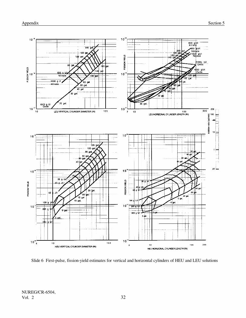
Slide 6 provides the "First Pulse Fission Yield Estimates for Vertical and Horizontal Cylinders of HEU and LEU Solutions" and oxides. Slide 6 also consists of five interrelated graphs. The mid-right, vertical-logarithmic scalehas an arrow pointer labeled "Addition rate (gal/min)." The top-left graph provides the "Fission Yield" for a"LEU Vertical Cylinder Diameter (in.)" based upon the uranyl nitrate solution or uranium oxide uranium density(g U/L) and the solution or oxide addition rate. The top-right graph provides identical information for a "LEUHorizontal Cylinder Length (in.)." The bottom-left, 2-D graph provides the fission yield for a "HEU VerticalCylinder Diameter (in.)" based upon a uranium solution density (g U/L) and the solution addition rate. Thebottom-right graph provides identical information for a "HEU Horizontal Cylinder Length (in.)."
Slide 6 may also be used in a forward or backward manner: That is, based upon a solution addition rate, solutionuranium density, cylinder dimension (diameter or length) and cylinder orientation (vertical or horizontal), afission yield may be estimated. For example, given a 30-g HEU/L addition rate of 0.4 gal/min into a 26-in.-diamvertical cylinder provides a first-pulse fission yield of about 9 × 10¹⁶ fissions at a volume of approximately 23 galof solution. Assuming that the given configuration will become subcritical at less than 23 gal of solution, if thereis a 5-gal (i.e., 18.94-L) excess of solution, then, from the "Conversion Factors and Equalities" it will requireapproximately an additional (18.94 L)·(1017 fissions/L) or 1.9 × 10¹⁸ fissions to evaporate enough water to cause

Section 2 Explanation of Slide Rule
NUREG/CR-6504,Vol. 25
the system to be subcritical. Alternatively, Slide 6 may be used in a backward manner by selecting a fissionyield and examining the parameters resulting in that fission yield.
2.3 CONVERSION FACTORS AND EQUALITIES
The listing of conversion factors and equalities are provided for handy reference in the interpretation of field dataor translation of the slide rule to field applications. Some guidance is provided, such as the number of fissionsrequired to evaporate 1 L of room-temperature water and the number of fissions produced over a time period fora given volume of solution. Such rules-of-thumb are inherently approximate and may be influenced by complexmechanisms. However, the application of these rules-of-thumb should be accurate within about a factor of 2.
2.4 REFERENCE FIGURES
Figures 1 through 15 are provided as comparative references to potential systems of interest for emergencyplanning, preparedness, training, and response. They may be used for approximating the radiation dose reductiondue to concrete, steel, and water (Figure 1) or for approximating the critical parameters of idealized water-reflected critical systems (Figures 2 through 15). The figures are not included for the purpose of preciselyevaluating shielding and subcritical or critical systems. Precise nuclear criticality safety evaluations for normaland credible abnormal fissile material conditions should be performed by experienced nuclear criticality safetyspecialists who are familiar with computational evaluations and analyses of the normal and abnormal fissilematerial processes that will influence the approach to the critical state.
Figure 1a provides the effective prompt fission neutron- and gamma-radiation, dose-reduction factors formultiple layers of a specified shielding material located at 24-ft intervals from the criticality accident out to adistance of 240 ft. The thicknesses of the thin shielding materials considered were 1-in. (2.54-cm)-thick layers ofsteel, or 3-in. (7.62-cm)-thick layers of concrete, or 3-in. (7.62-cm)-thick layers of water. The purpose ofevaluating multiple thin layers of shielding materials was to simulate the effects of walls and equipment that maybe intervening between operating areas of a facility. Because the dose-reduction factors are based upon coupledneutron-gamma calculations the influence of neutron-capture gammas is included in the gamma-radiation, dose-reduction factor.
Figure 1b provides extrapolated prompt fission neutron and delayed fission-product gamma radiation dosereduction factors for thin single shields of material (i.e., steel, concrete, or water) located approximately 10 ftfrom the criticality accident. The shielding effectiveness differences from Figure 1a are due to the higher energyof the nearly first-collision neutrons on the shield and the lower-energy, delayed fission-product-gammaradiation not having a neutron-capture-gamma component.
Figures 2 through 15 provide approximate critical parameters for various fully water-reflected geometries (i.e.,spheres, infinitely long cylinders, and slabs having infinite lateral dimensions) for water-moderated systems oflow-enriched uranium (LEU � 2.5, 3, 4, 5, and 6 wt % 235U in uranium) and high-enriched uranium (HEU �93 wt % 235U in uranium).

Explanation of Slide Rule Section 2
NUREG/CR-6504,Vol. 2 6
������������� ���
Figure 1 Dose reduction factors for various shield thicknesses
������������� ���
(a) prompt radiation dose-reduction factors for multiple thin shields
(b) prompt neutron and delayed gamma dose-reduction factors for single shields

Section 2 Explanation of Slide Rule
NUREG/CR-6504,Vol. 27
Figure 2 LEU UO2�H2O critical sphere volume (L) vs uranium mass (kg)

Explanation of Slide Rule Section 2
NUREG/CR-6504,Vol. 2 8
Figure 3 LEU UO2�H2O critical sphere diameter (in.) vs uranium density (g/L)

Section 2 Explanation of Slide Rule
NUREG/CR-6504,Vol. 29
Figure 4 LEU UO2�H2O critical sphere uranium mass (kg) vs uranium density (g/L)

Explanation of Slide Rule Section 2
NUREG/CR-6504,Vol. 2 10
Figure 5 LEU UO2�H2O critical infinite cylinder uranium linear density (kg/ft) vs diameter (in.)

Section 2 Explanation of Slide Rule
NUREG/CR-6504,Vol. 211
Figure 6 LEU UO2�H2O critical infinite cylinder diameter (in.) vs uranium density (g/L)

Explanation of Slide Rule Section 2
NUREG/CR-6504,Vol. 2 12
Figure 7 LEU UO2�H2O critical infinite slab uranium areal density (kg/ft2 ) vs thickness (in.)

Section 2 Explanation of Slide Rule
NUREG/CR-6504,Vol. 213
Figure 8 LEU UO2�H2O critical infinite slab thickness (in.) vs uranium density (g/L)

Explanation of Slide Rule Section 2
NUREG/CR-6504,Vol. 2 14
Figure 9 HEU UO2(NO3)2�H2O critical sphere volume (L) vs uranium mass (kg)

Section 2 Explanation of Slide Rule
NUREG/CR-6504,Vol. 215
Figure 10 HEU UO2(NO3)2�H2O critical sphere uranium mass (kg) vs uranium density (g/cm3 )

Explanation of Slide Rule Section 2
NUREG/CR-6504,Vol. 2 16
Fig
ure
11 H
EU
UO
2(N
O3)
2�
H2O
cri
tica
l sph
ere
diam
eter
(in
.) v
s ur
aniu
m d
ensi
ty (
g/cm
3 )

Section 2 Explanation of Slide Rule
NUREG/CR-6504,Vol. 217
Fig
ure
12 H
EU
UO
2(N
O3)
2�
H2O
cri
tica
l inf
init
e cy
lind
er d
iam
eter
(in
.) v
s ur
aniu
m d
ensi
ty (
g/cm
3 )

Explanation of Slide Rule Section 2
NUREG/CR-6504,Vol. 2 18
Figure 13 HEU UO2(NO3)2�H2O critical cylinder uranium linear density (kg/ft) vs diameter (in.)

Section 2 Explanation of Slide Rule
NUREG/CR-6504,Vol. 219
Figure 14 HEU UO2(NO3)2�H2O critical slab uranium areal density (kg/ft2 ) vs thickness (in.)

Explanation of Slide Rule Section 2
NUREG/CR-6504,Vol. 2 20
Fig
ure
15 H
EU
UO
2(N
O3)
2�
H2O
cri
tica
l sla
b th
ickn
ess
(in.
) vs
ura
nium
den
sity
(g/
cm3 )

NUREG/CR-6504,Vol. 221
3 SUMMARY/CONCLUSIONS
This slide rule is a functional update to the original slide rule published in limited form in the early 1970s. Thegeneral format and features of the original slide rule are retained, in that the various curves include a prompt-dose-vs-distance relationship, a fission-product, gamma-dose-rate-vs-distance-and-time relationship, a total-dose-vs-time-and-distance relationship, and a 1-min total-dose-vs-time-and-distance relationship. The originalslide rule consisted of only two system types � highly enriched uranium solutions and metal � and contained anumber�of approximations, namely an assumed inverse-square relationship of neutron and gamma-ray doses withdistance. The newly updated slide rule contains information for the following five systems:
1. unreflected sphere of 4.95 wt % enriched aqueous uranyl fluoride, U(4.95)O2F2�H2O, solution having ahydrogen-to-235U ratio of 410 (solution density = 2.16 g/cm3),
2. unreflected sphere of damp 5 wt % enriched uranium dioxide, U(5)O2 having a hydrogen-to-235U ratio of 200,
3. unreflected sphere of 93.2 wt % enriched uranyl nitrate, U(93.2)O2(NO3)2�6H2O, solution having a hydrogen-to-235U atom ratio of 500 (solution density = 1.075 g/cm3),
4. unreflected sphere of 93.2 wt % enriched uranium metal sphere (metal density = 18.85 g/cm3), and
5. unreflected sphere of damp 93.2 wt % enriched uranium oxide, U3O8 plus water, having a hydrogen-to-235Uatom ratio of 10 (uranium oxide density = 4.15 g/cm3).
This update also includes not only the air/ground interface effects near the assumed accident, but out to 4000 ft(1219.2 m) as well. The possibility of a shielded criticality accident in which skyshine radiation can beimportant is also treated, with the inclusion of a separate skyshine contribution as a function of distance from theaccident. Also, results of first-pulse, fission-yield estimate evaluations are presented as functions of vertical orhorizontal cylindrical critical volumes (based upon the degree of fissile material moderation expressed in termsof uranium density and cylinder dimension) and material addition rates. The first-pulse, fission-yield estimatesmay then be used for determining appropriate mitigating measures for protection of personnel as an uncontrolledsystem approaches criticality.
Though the presentation of dose and dose-rate information for less than 1 min (i.e., 1 to 60 s elapsed time)following the initial or prompt fission yield has no use for an emergency response, the information is useful foremergency preparedness in the training of personnel to respond quickly to a criticality accident alarm or in theestimation of radiation fields at the time of the accident, or very shortly thereafter.

NUREG/CR-6504,Vol. 2 22

NUREG/CR-6504,Vol. 223
4 REFERENCES
1. C. M. Hopper, Slide Rule for Estimating Nuclear Criticality Information, Y-DD-145,Union Carbide Corp., Nucl. Div., Oak Ridge Natl. Lab., 1974.
2. R. D. Carter, G. R. Kiel, and K. R. Ridgway, Criticality Handbook, ARH-600, Vol. II,Atlantic Richfield Hanford Co., Richland, Wash., May 23, 1969.
3. F. Barbry, "Model to Estimate the Maximum Fission Yield in Accidental Solution Excursions,"Trans. Am. Nucl. Soc. 55, 412-414 (1987).

NUREG/CR-6504,Vol. 2 24

NUREG/CR-6504,Vol. 225
5 APPENDIX
CONTENTS
Slide 1 Solution of U(93.2)O2(NO3)2 @ H/235U = 500
Slide 2 U(93.2) metal
Slide 3 Damp U(93.2)3O8 @ H/ 235U = 10
Slide 4 Damp U(4.95)O2F2 @ H/ 235U = 410
Slide 5 Damp U(5)O2 @ H/ 235U = 200
Slide 6 First-pulse, fission-yield estimates for vertical and horizontal cylinders of HEU and LEU solutions
CONVERSION FACTORS AND EQUALITIES

Appendix Section 5
NUREG/CR-6504,Vol. 2 26

Section 5 Appendix
NUREG/CR-6504,Vol. 227
Slide 1 Solution of U(93.2)O2(NO3)2 @ H/235U = 500

Appendix Section 5
NUREG/CR-6504,Vol. 2 28
Slide 2 U(93.2) metal

Section 5 Appendix
NUREG/CR-6504,Vol. 229
Slide 3 Damp U(93.2)3O8 @ H/ 235U = 10

Appendix Section 5
NUREG/CR-6504,Vol. 2 30
Slide 4 Damp U(4.95)O2F2 @ H/ 235U = 410

Section 5 Appendix
NUREG/CR-6504,Vol. 231
Slide 5 Damp U(5)O2 @ H/ 235U = 200
Appendix Section 5
NUREG/CR-6504,Vol. 2 32
Slide 6 First-pulse, fission-yield estimates for vertical and horizontal cylinders of HEU and LEU solutions
NUREG/CR-6504,Vol. 233
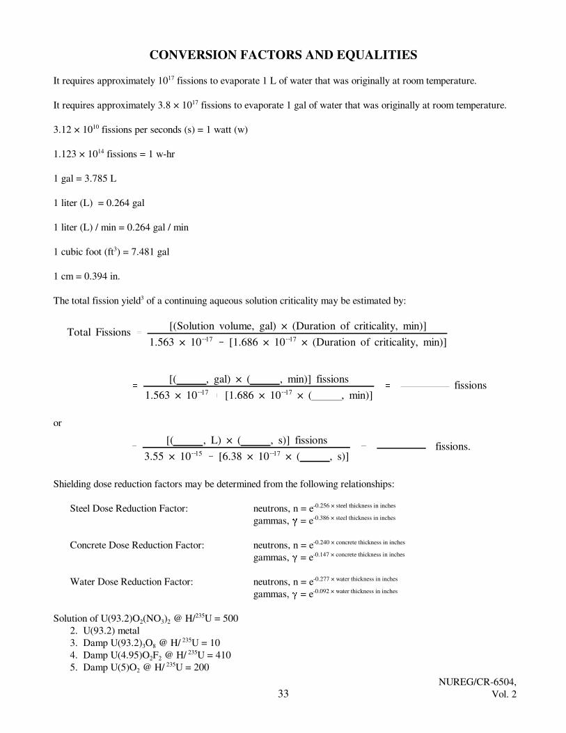
Total Fissions �
[(Solution volume, gal) × (Duration of criticality, min)]
1.563 × 10�17� [1.686 × 10�17 × (Duration of criticality, min)]
�
[( , gal) × ( , min)] fissions
1.563 × 10�17� [1.686 × 10�17 × ( , min)]
� fissions
�
[( , L) × ( , s)] fissions
3.55 × 10�15� [6.38 × 10�17 × ( , s)]
� fissions.
CONVERSION FACTORS AND EQUALITIES
It requires approximately 1017 fissions to evaporate 1 L of water that was originally at room temperature.
It requires approximately 3.8 × 10¹⁷ fissions to evaporate 1 gal of water that was originally at room temperature.
3.12 × 10¹⁰ fissions per seconds (s) = 1 watt (w)
1.123 × 10¹⁴ fissions = 1 w-hr
1 gal = 3.785 L
1 liter (L) = 0.264 gal
1 liter (L) / min = 0.264 gal / min
1 cubic foot (ft3) = 7.481 gal
1 cm = 0.394 in.
The total fission yield3 of a continuing aqueous solution criticality may be estimated by:
or
Shielding dose reduction factors may be determined from the following relationships:
Steel Dose Reduction Factor: neutrons, n = e-0.256 × steel thickness in inches
gammas, � = e-0.386 × steel thickness in inches
Concrete Dose Reduction Factor: neutrons, n = e-0.240 × concrete thickness in inches
gammas, � = e-0.147 × concrete thickness in inches
Water Dose Reduction Factor: neutrons, n = e-0.277 × water thickness in inches
gammas, � = e-0.092 × water thickness in inches
Solution of U(93.2)O2(NO3)2 @ H/235U = 5002. U(93.2) metal3. Damp U(93.2)3O8 @ H/ 235U = 104. Damp U(4.95)O2F2 @ H/ 235U = 4105. Damp U(5)O2 @ H/ 235U = 200

NUREG/CR-6504,Vol. 2 34

NUREG/CR-6504,Vol. 235
NUREG/CR-6504, Vol. 2ORNL/TM-13322/V2
INTERNAL DISTRIBUTION
1.2.3.4.5.6.
7-15.16.17.18.19.20.
21-25.26.27.28.29.30.
J. F. AlexanderE. G. BailiffJ. S. BakerL. J. BowieS. M. BowmanB. L. BroadheadW. C. Carter (9)R. L. ChildsG. D. EllisM. B. EmmettG. R. HandleyO. W. HermannC. M. Hopper (5)M. A. KuliashaK. D. LewisM. S. MacherR. C. MarbleJ. F. Mincey
31.32.33.34.35.36.37.38.39.40.
41-43.44.45.
46.47-48.
49.50.
J. V. PaceC. V. ParksL. M. PetrieC. E. PughJ.-P. RenierR. C. RobinsonJ. E. RushtonC. H. ShappertJ. A. SmithJ. S. TangR. G. Taylor (3)R. M. WestfallCentral Research Library, Document Reference SectionORNL-Y-12 Technical LibraryORNL Laboratory Records (2)ORNL Laboratory Records, RCORNL Patent Section
EXTERNAL DISTRIBUTION
51-60. F. M. Alcorn (10), Babcock and Wilcox, NNFD, 212 Windsor Rd., Lynchburg,VA 24502
61. P. Alesso, Lawrence Livermore National Laboratory, Nuclear Engineering Section,Mail Stop L-196, P.O. Box 808, Livermore CA 94550
62. H. N. Amirmokri, U.S. DOE GTN/NE-40, Office of Facilities, 19901 GermantownRoad, Germantown, MD 20874-1290
63. R. E. Anderson, Los Alamos National Laboratory, TA-18 Bldg. 0030, Room 109,NIS-6, MS J562, Los Alamos, NM 87545
64. M. G. Bailey, U.S. Nuclear Regulatory Commission, MS O-6 G22, Washington,DC 20555-0001

NUREG/CR-6504,Vol. 2 36
65. W. D. Baltimore, Lockheed Martin Utility Services, Paducah Gaseous DiffusionPlant, C-102-T-06, P.O. Box 1410, Paducah, KY 42002
66. G. L. Bennett, 5000 Butte Road, Emmett, ID 8361767. K. E. Bhanot (ANSI/ANS-8.23 WG), BNFL Fuel Division, Springfields, Salwick,
Preston, Lancashire PR4 OXJ, United Kingdom68. S. K. Bhatnagar, U.S. DOE GTN/EH-32, Office of Facility Safety Analyses,
19901 Germantown Road, Germantown, MD 20874-129069. W. A. Blykert (ANSI/ANS-8.23 WG), Mohr & Associates, 1820 Howell Avenue,
Richland, WA 9935270. S. P. Burris (ANSI/ANS-8.23 WG), American Management Services, Inc.,
421 Gay Street, Erwin, TN 3765071. R. Busch, Chemical & Nuclear Engr., Dept. FEC 209, University of New Mexico,
Albuquerque, NM 87131-134172. D. E. Cabrilla, U.S. DOE EM-66, Nuclear Material Stabilization, 19901
Germantown Road, Germantown, MD 20874-129073. G. Campbell, Senior Emergency Planner, Fluor Daniel Fernald, P.O. Box 398704,
Cincinnati, OH 45239-870474. D. E. Carlson, U.S. Nuclear Regulatory Commission, NMSS Spent Fuel Project
Office, MS O-6 G22, Washington, DC 20555-000175. R. W. Carson (ANSI/ANS-8.23 WG), Babcock and Wilcox, NNFD,
P.O. Box 785, Lynchburg, VA 2450576. M. H. Chew, M. H. Chew & Associates, Inc., 1424 Concannon Blvd., Livermore,
CA 94550-600677. J.-S. Choi (ANSI/ANS-8.23 WG), Lawrence Livermore National Laboratory,
P.O. Box 808, MS L-634, Livermore, CA 9455178. J. Conant, Combustion Engineering, Inc., 2000 Day Hill Road, Windsor, CT 0609579. G. F. Couture (ANSI/ANS-8.23 WG), Westinghouse Savannah River Company,
Bldg. 707-C, Room 332, Aiken, SC 2980280. E. C. Crume, Jr., 115 Orkney Road, Oak Ridge, TN 3783081. D. Damon, U.S. Nuclear Regulatory Commission, MS T-8D14, Washington, DC
20555-000182. D. M. D’Aquila (ANSI/ANS-8.23 WG), Lockheed Martin Utility Services, Inc.,
P.O. Box 628, MS 1110A, Piketon, OH 4566183. J. C. Dean, Science Applications International Corp., 301 Laboratory Road,
Oak Ridge, TN 3783084. H. L. Dodds, University of Tennessee, Nuclear Engr. Dept., 315 Pasqua Bldg.,
Knoxville, TN 37996-230085. A. L. Doherty, Engineering and Analytical Science Department, Battelle Pacific
Northwest National Laboratory, Mail Stop K8-34, P.O. Box 999, Richland, WA99352

NUREG/CR-6504,Vol. 237
86. P. Felsher, Rocky Flats Environment Technology Site, Bldg. T886B,P.O. Box 464, Golden, CO 80402-0464
87. I. E. Fergus, Jr., U.S. DOE GTN/EH-22, Office of Environmental Safety & HealthEvaluation, 19901 Germantown Road, Germantown, MD 20874-1290
88. R. W. Fliszar, Department of the Army, Development and Engineering Center,Picatinny Arsenal, Dover, NJ 07806
89. L. E. Gordon-Hagerty, U.S. DOE GTN/DP-23, Office of Emergency Response,19901 Germantown Road, Germantown, MD 20874-1290
90. L. Graber, Licensing Engineer, NUS Information Services, Licensing InformationService, 2650 McCormick Drive, Suite 300, Clearwater, FL 33759
91. C. F. Guenther, M. H. Chew & Associates, Inc., 1424 Concannon Blvd.,Livermore, CA 94550-6006
92. J. Gustafsson, Senior Specialist Radiology, ABB Atom AB, Safeguards and Safety,S 721 63 Vasteras/ Sweden
93. K. Hardin, U.S. Nuclear Regulatory Commission, MS T-8 D14, Washington, DC20555-0001
94. D. K. Hayes, DNFSB, 625 Indiana Ave. NW, Suite 700, Washington, DC 2000495-106. B. E. Hey (12), Fluor Daniel Northwest, Mail Stop A3-34, P.O. Box 1050,
Richland, WA 99352-1050107. J. Hicks, Rocky Flats Environment Technology Site, Bldg. T886B, P.O. Box 464,
Golden, CO 80402-0464108. A. G. Hodgson, East Tennessee Technology Park, Building K-1650, MS 7305,
Oak Ridge, TN 37831-7305109. R. Hogan, U.S. Nuclear Regulatory Commission, MS T-4 A43, Washington, DC
20555-0001110. C. Hrabal, U.S. Nuclear Regulatory Commission, MS T-8 D14, Washington, DC
20555-0001111. S. Huang, Lawrence Livermore National Laboratory, MC L128, 7000 East Ave.,
P.O. Box 808, Livermore, CA 94550112. J. C. Ingram, III, East Tennessee Technology Park, Building K-1001, Rm-B111,
Oak Ridge, TN 37831-7130113. Y. Kim, Halliburton NUS Corp., 910 Clopper Road, Gaithersburg, MD 20877114. K. D. Kimball, NISYS Corporation, 6055 Atlantic Blvd, Suite G-2, Norcross, GA
30071115. R. Koopman, Lawrence Livermore National Laboratory, P.O. Box 808, L-467,
Livermore, CA 94551116. M. D. Kosmider, Allied Signal, Inc., P.O. Box 430, Metropolis, IL 62960117. S. L. Larson, Engineering and Analytical Science Department, Battelle Pacific
Northwest National Laboratory, Mail Stop K8-34, P.O. Box 999, Richland, WA99352

NUREG/CR-6504,Vol. 2 38
118. D. J. Lindenschmidt (ANSI/ANS-8.23 WG), Parallax, 6626 Station Road,West Chester, OH 45069
119. C. D. Manning, Siemens Power Corporation, Nuclear Division, Engineering andManufacturing Facility, 2101 Horn Rapids Road, P.O. Box 130, Richland, WA99352-0130
120. C. W. Ma, M. H. Chew & Associates, Inc., 1424 Concannon Blvd., Livermore,CA 94550-6006
121. L. J. Maas, Siemens Power Corp., 2101 Horn Rapids Road, Richland, WA 99352122. R. C. McBroom, U.S. DOE Oak Ridge Operations, Corporate Support Team
SE-32, P.O. Box 2001, Oak Ridge, TN 37831-8732123. J. N. McKamy, U.S. DOE GTN/EH-34, Office of Eng Asssistance & Site Interf,
19901 Germantown Road, Germantown, MD 20874-1290124. T. McKenna, U.S. Nuclear Regulatory Commission, MS T-4A43, Washington, DC
20555-0001125-130. T. P. McLaughlin (6), Los Alamos National Laboratory, Criticality Safety, ES-6,
Bldg. SM-43, Rm A 108, M/S F691, Los Alamos, NM 87545131. R. D. Montgomery, Nuclear Fuel Services, Inc., 1205 Banner Hill Road, Erwin,
TN 37650132. N. A. Moon, U.S. DOE Rocky Flats Office, Highway 93rd & Cactus Street,
Golden, CO 80402133. J. A. Morman, Argonne National Laboratory, RE 208 C237B, 9700 South Cass
Ave., Argonne, IL 60439134. D. R. Nelson, U.S. DOE GTN/ER-8, Office of Envir, Safety & Health Tech,
19901 Germantown Road, Germantown, MD 20874-1290135. C. W. Nilsen, Office of Nuclear Regulatory Research, U.S. Nuclear Regulatory
Commission, MS T-9 F31, Washington, DC 20555-0001136. S. Parra, U.S. Nuclear Regulatory Commission, MS T-8 A33, Washington, DC
20555-0001137. L. E. Paulson, Manager, Nuclear Safety, GE Nuclear Energy, P.O. Box 780,
Castle Hayne Road, Wilmington, NC 28402138. S. S. Payne, U.S. DOE AL, Building 381-3, Pennsylvania & H Street, Kirtland Air
Force Base, Albuquerque, NM 87116139. J. K. Paynter, M. H. Chew & Associates, Inc., 1424 Concannon Blvd., Livermore,
CA 94550-6006140. R. E. Pevey, University of Tennessee, Nuclear Engr. Dept., 315 Pasqua Bldg.,
Knoxville, TN 37996-2300141. J. S. Philbin, Sandia National Laboratories, New Mexico, P.O. Box 5800,
Albuquerque, NM 87185-1143142. A. W. Prichard, Engineering and Analytical Science Department, Battelle Pacific
Northwest National Laboratory, Mail Stop K8-34, P.O. Box 999, Richland, WA99352

NUREG/CR-6504,Vol. 239
143. N. L. Pruvost, Galaxy Computer Services, Inc., 551 W. Cordova Road, Suite 202,Santa Fe, NM 87501-4143
144. V. L. Putman (ANSI/ANS-8.23 WG), Lockheed Martin Idaho TechnologiesCompany, P.O. Box 1625, Idaho Falls, ID 83415-3458
145. M. Ragheb, University of Illinois, Department of Nuclear Engineering,103 S. Goodwin Avenue, 223 NEL, Urbana, IL 61801
146. R. L. Reed (ANSI/ANS-8.23 WG), Westinghouse Savannah River Co.,Bldg. 730-B, Room 3444, Savannah River Site, Aiken, SC 29802
147-156. T. A. Reilly (10), Westinghouse Savannah River Company, Building 707-F, Aiken,SC 29808
157-162. C. Rogers (6), Lockheed Martin Hanford Corp., MSIN R1-56, P.O. Box 1500,Richland, WA 99352-1500
163. C. T. Rombough, CTR Technical Services, Inc., 950 Sugarloaf Road, ManitouSprings, CO 80829
164. G. G. Rosenberger, Nuclear Fuel Services, Inc., 1205 Banner Hill Road, Erwin,TN 37650
165. B. M. Rothleder, U.S. DOE GTN/EH-31, Office of Nuclear Safety Policy & Stnds,19901 Germantown Road, Germantown, MD 20874-1290
166-168. B. Rumble (3), Lockheed Martin Utility Services, Inc., MS-5023, P.O. Box 628,Piketon, OH 45661
169. S. R. Salaymeh (ANSI/ANS-8.23 WG), Westinghouse Savannah River Co.,Bldg. 773, Room 41A, Savannah River Site, Aiken, SC 29802
170. R. Shackelford, Nuclear Safety Manager, Fluor Daniel Fernald, P.O. Box 398704,Cincinnati, OH 45239-8704
171. J. S. Schaefer (ANSI/ANS-8.23 WG), AECL, Chalk River Laboratories,Chalk River, Ontario, Canada KOJ 1JO
172. R. W. Sharkey, Combustion Engineering, Inc., 3300 State Road P, Hematite, MO63047
173. R. V. Stachowiak, Rocky Flats Environmental Technology Site, Box 464, Golden,CO 80402-0464
174. G. L. Stimmell, Manager, General Electric Co., Vallecitos Nuclear Center,P.O. Box 460, Vallecitos Road, Pleasanton, CA 94566
175. R. Tayloe (ANSI/ANS-8.23 WG), Battelle, Room 11-10-070, 505 King Avenue,Columbus, OH 43201
176. J. T. Taylor, Principle Engineer - CSE, GE Nuclear Energy, P.O. Box 780,Castle Hayne Road, Wilmington, NC 28402
177. J. T. Taylor, Idaho National Engineering & Environmental Lab, ICPP,P.O. Box 1625, Idaho Falls, ID 83415-3458
178-182. M. L. Thomas, U.S. Nuclear Regulatory Commission, MS T-9 C24, Washington,DC 20555-0001
183. J. W. Thompson (ANSI/ANS-8.23 WG), Atlantic Nuclear Services, Ltd.,P.O. Box 1268, Station A, Fredericton, New Brunswick, Canada, E3B 5C8
NUREG/CR-6504,Vol. 2 40
184. P. R. Thorne (ANSI/ANS-8.23 WG), BNFL, R101, Rutherford House, Risley,Warington, Cheshire, WA3 6AS, UK
185. H. Toffer, Rocky Flats Environment Technology Site, P.O. Box 464,Bldg. T886C, Golden, CO 80402-0464
186. E. G. Wallace, Tennessee Valley Authority, 5N 1578 Lookout Place, Chattanooga,TN 37401
187. H. W. Webb (ANSI/ANS-8.23 WG), Nuclear Fuel Services, Inc., 1205 Banner HillRoad, Erwin, TN 37650-9718
188. P. S. Webb, M. H. Chew & Associates, Inc., 1424 Concannon Blvd., Livermore,CA 94550-6006
189. D. W. Williams, Westinghouse Electric Corporation, 5801 Bluff Rd MS#15,Columbia, SC 29209
190. R. E. Wilson, Rocky Flats Environment Technology Site, Bldg. T886B,P.O. Box 464, Golden, CO 80402-0464
191. C. J. Withee, U.S. Nuclear Regulatory Commission, MS O-6 G22, Washington,DC 20555-0001
192. P. J. Vescovi, Senior Engineer - CSE, GE Nuclear Energy, P.O. Box 780,Castle Hayne Road, Wilmington, NC 28402
193. Fuel Facility Resident Inspector, U.S. NRC-Reg I, 475 Allendale Road,King of Prussia, PA 19406
194-195. Fuel Facility Resident Inspector (2), U.S. NRC-Reg II, 101 Marietta Street, NW,Suite 2900, Atlanta, GA 30323
196-197. Fuel Facility Resident Inspector (2), U.S. NRC-Reg III, 801 Warrenville Road,Lisle, IL 60532
198. Fuel Facility Resident Inspector, U.S. NRC-Reg IV, 611 Ryan Plaza Drive,Suite 400, Arlington, TX 76011
199. U.S. NRC-NMSS, Division of Fuel Cycle Safety and Safeguards, Branch Chief,Enrichment Branch, MS T-8 A33, Washington, DC 20555-0001
200. U.S. NRC-NMSS, Division of Industrial and Medical Nuclear Safety,Deputy Director, MS T-8 F5, Washington, DC 20555-0001
201. U.S. NRC-NMSS, Division of Industrial and Medical Nuclear Safety, Director,MS T-8 F5, Washington, DC 20555-0001
202. U.S. NRC-NMSS, Office Director, MS T-8A23, Washington, DC 20555-0001203. U.S. NRC-NMSS, Spent Fuel Project Office, Director, MS O-6 F18, Washington,
DC 20555-0001204. U.S. NRC-RES, Division of Regulatory Applications, Director, MS T-9 F33,
Washington, DC 20555-0001205. U.S. NRC-RES, Division of Regulatory Applications, Radiation Protection and
Health, Effects Branch Branch Chief, MS T-9 F24, Washington, DC 20555-0001206. U.S. NRC-Reg I, Regional Administrator, 475 Allendale Road, King of Prussia,
PA 19406

NUREG/CR-6504,Vol. 241
207. U.S. NRC-Reg II, Regional Administrator, 101 Marietta Street, NW, Suite 2900,Atlanta, GA 30323
208. U.S. NRC-Reg III, Regional Administrator, 801 Warrenville Road, Lisle, IL 60532209. U.S. NRC-Reg IV, Regional Administrator, 611 Ryan Plaza Drive, Suite 400,
Arlington, TX 76011

42

43
NRC FORM 335 U.S. NUCLEAR REGULATORY COMMISSION(2-89)NRCM 1102 BIBLIOGRAPHIC DATA SHEET3201, 3202 (See instructions on the reverse)
1. REPORT NUMBER(Assigned by NRC, Add Vol., Supp.,Rev., and Addendum Numbers,
if any.)
NUREG/CR-6504, Vol. 2ORNL/TM-13322/V22. TITLE AND SUBTITLE
An Updated Nuclear Criticality Slide Rule
Functional Slide Rule3. DATE REPORT PUBLISHED
MONTH
AprilYEAR
1998
4. FIN OR GRANT NUMBER
W6303
5. AUTHOR(S)
C. M. Hopper, B. L. Broadhead
6. TYPE OF REPORT
Technical
7. PERIOD COVERED (Inclusive Dates)
8. PERFORMING ORGANIZATION — NAME AND ADDRESS (If NRC, provide Division, Office or Region, U.S. Nuclear Regulatory Commission, and mailingaddress; if contractor, provide name and mailing address.)
Oak Ridge National LaboratoryPost Office Box 2008Oak Ridge, Tennessee 37831-6370
9. SPONSORING ORGANIZATION — NAME AND ADDRESS (If NRC, type “Same as above”; if contractor, provide NRC Division, Office or Region, U.S. RegulatoryCommission, and mailing address.)
Division of Regulatory ApplicationsOffice of Nuclear Regulatory ResearchU.S. Nuclear Regulatory CommissionWashington, DC 20555-0001
10. SUPPLEMENTARY NOTES
M. L. Thomas, NRC Project Manager
11. ABSTRACT (200 words or less)
This Volume 2 contains the functional version of the updated nuclear criticality slide rule (more accurately, slidinggraphs) that is referenced in An Updated Nuclear Criticality Slide Rule: Technical Basis, NUREG/CR-6504, Vol. 1(ORNL/TM-13322/V1). This functional slide rule provides a readily usable “in-hand” method for estimating pertinentnuclear criticality accident information from sliding graphs, thereby permitting (1) the rapid estimation of pertinentcriticality accident information without laborious or sophisticated calculations in a nuclear criticality emergencysituation, (2) the appraisal of potential fission yields and external personnel radiation exposures for facility safetyanalyses, and (3) a technical basis for emergency preparedness and training programs at nonreactor nuclear facilities. The slide rule permits the estimation of neutron and gamma dose rates and integrated doses based upon estimatedfission yields, distance from the fission source, and time-after criticality accidents for five different critical systems. Another sliding graph permits the estimation of critical solution fission yields based upon fissile materialconcentration, critical vessel geometry, and solution addition rate. Another graph provides neutron and gamma dose-reduction factors for water, steel, and concrete. Graphs from historic documents are provided as references forestimating critical parameters of various fissile material systems. Conversion factors for various English and metricunits are provided for quick reference.
12. KEY WORDS/DESCRIPTORS (List words or phrases that will assist researchers in locating the report.)
emergency planning, emergency response, nuclear criticality accident, slide rule,fission yields, shielding, radiation protection
13. AVAILABILITY STATEMENT
unlimited
14. SECURITY CLASSIFICATION
(This Page) unclassified
(This Report) unclassified
15. NUMBER OF PAGES
16. PRICE
���������������������� ��

44


![[ON TIME-CRITICALITY] TIME-CRITICALITY … · ["ON TIME-CRITICALITY"] TIME-CRITICALITY Time-critical signal processing in humans and machines ... - ancient Greek prosody based on](https://static.fdocuments.net/doc/165x107/5b914fb509d3f215288b5a2b/on-time-criticality-time-criticality-on-time-criticality-time-criticality.jpg)