An Underactuated Propeller for Attitude Control in Micro ...
6
An Underactuated Propeller for Attitude Control in Micro Air Vehicles James Paulos and Mark Yim Abstract— Traditional coaxial helicopter micro air vehicles use a large propeller motor in conjunction with two small servomotors to control thrust, pitch, and roll forces and mo- ments. Quadrotors similarly generate these necessary forces and moments through the coordinated control of multiple actuators. We present a novel propeller architecture which allows a single motor and rotor to express such control by modulating the torque applied to one passively hinged, underactuated propeller. Flight tests of a two-motor coaxial helicopter demonstrate that such a system can provide active stability and control in a real flight system. I. I NTRODUCTION Large scale unmanned air vehicles (UAV) have provided an eye in the sky to support a variety of applications. Imagining future roles for UAVs in cluttered urban settings or indoor environments has driven efforts towards palm-sized micro air vehicles (MAV). The small size of MAVs can permit them to be uniquely agile [1]. In addition to being able to physically access confined spaces, their low inertia further allows the possibility of safe, recoverable collisions with structures and people [2]. Hover-capable MAVs are of particular interest for indoor applications, with examples including quadrotors [3], coaxial helicopters [4], [5], and ornithopers [6], [7]. The present miniaturization of MAVs owes primarily to advances in improved battery power densities, better use of light composite materials, shrinking electrical components and MEMS sensors. A principle difficulty lies in the fact that as these flight systems have grown smaller, their complex- ity has remained largely unchanged. A one hundred gram quadrotor or coaxial helicopter is nearly a component-for- component replica of its one kilogram or even ten kilo- gram cousin, at a smaller scale. This direct miniaturization has proven easier for some architectures, with the simple motor and fixed pitch propeller of quadrotors being more cooperative than the servo-driven swashplate mechanisms of common coaxial helicopters. Most contemporary MAVs capable of hover and vertical flight employ similar lifting rotors for thrust but differentiate themselves through the way in which attitude control mo- ments are achieved. Traditional helicopter design has been informed by the assumption that large thrust actuators have slow characteristic response, necessitating separate actuators and a complex linkage system for high bandwidth attitude control. In contrast, four-rotor “quadrotor” flight systems have shown that this strict dichotomy need not hold, and these devices instead coordinate multiple identical rotors to achieve both thrust and moment objectives. Finally, some efforts have been made to achieve both thrust and moment response from a single actuator using indirect drive through The authors are with the Dept. of Mech. Eng. & Appl. Mechanics and GRASP Lab at the University of Pennsylvania, Philadelphia, PA. [email protected], [email protected] a linkage [8]. This paper presents a new concept a MAV propulsion system capable of using a minimum number of actuators in dual rolls. This simplifies and lowers the cost of MAVs. Removing complex swash plates and reducing the number of actuators reduces the number of parts, thus increases reliability (fewer parts to fail), reduces maintenance costs, reduces vehicle mass, and reduces manufacturing costs. Experimental results for the actuator response are presented along with a demonstration of a full flight vehicle using this system for both active stability and maneuvering. II. CONTROL CONCEPT Traditional small scale helicopters and coaxial helicopters already use a single rotor to generate both thrust force and attitude moments. Broadly speaking, thrust comes from the average speed and angle of attack of the propeller blade, and attitude moments are derived from an added cyclic oscillation in the angle of attack through each revolution. This cyclic pitching blade motion is ordinarily proscribed by a swashplate linkage driven by two or three additional servomotors and is sometimes augmented by the dynamics of a stabilizing flybar [9]. In contrast, we can attain this motion directly from a passive dynamic response of the propeller itself. For such a propeller the mean applied torque sets the rotational speed and thrust, and an applied oscillatory torque induces the desired cyclic oscillation in blade pitch. A simple realization for such an underactuated propeller consists of a rigid hub linked to two semi-rigid airfoil blades, as illustrated in Figs. 1-2. The vertical motor shaft is fixed to the central hub and transmits torque to the rotor hub. Propeller blades are attached to this hub on either side through simple hinges. The axes of the two hinges lie in the same plane as the vertical propeller axis of rotation, but they are not parallel to the axis of rotation as would be found in typical helicopter rotors. The blade denoted the ‘positive’ blade has the top of its hinge inclined towards the central shaft. Conceptually, this ‘positive’ rotor responds to an impulsive torque on the hub by flexing backwards and exposing increased blade pitch as shown in Fig. 3. Similarly, a retrograde torque causes the ‘positive’ rotor to flex forwards on its hinge and decrease its pitch. The opposing ’negative’ blade has the top of its hinge axis inclined away from the central shaft, and the complementary geometry creates an opposite response to torques. By superimposing a sinusoidal torque at the rotor frequency on top of the steady torque needed to balance rotor drag, a cyclic oscillation in blade pitch is induced that is phase locked with the rotor position. The motion is functionally similar to that proscribed by a swashplate mechanism, but it is now produced through actuation of only the single main motor. This motor can now generate attitude moments by, for example, selectively elevating blade pitch in the northern sector and decreasing it in the southern sector through each revolution. By changing 2013 IEEE/RSJ International Conference on Intelligent Robots and Systems (IROS) November 3-7, 2013. Tokyo, Japan 978-1-4673-6357-0/13/$31.00 ©2013 IEEE 1374
Transcript of An Underactuated Propeller for Attitude Control in Micro ...

An Underactuated Propeller for Attitude Control in Micro Air Vehicles
James Paulos and Mark Yim
Abstract— Traditional coaxial helicopter micro air vehiclesuse a large propeller motor in conjunction with two smallservomotors to control thrust, pitch, and roll forces and mo-ments. Quadrotors similarly generate these necessary forces andmoments through the coordinated control of multiple actuators.We present a novel propeller architecture which allows a singlemotor and rotor to express such control by modulating thetorque applied to one passively hinged, underactuated propeller.Flight tests of a two-motor coaxial helicopter demonstrate thatsuch a system can provide active stability and control in a realflight system.
I. INTRODUCTION
Large scale unmanned air vehicles (UAV) have providedan eye in the sky to support a variety of applications.Imagining future roles for UAVs in cluttered urban settingsor indoor environments has driven efforts towards palm-sizedmicro air vehicles (MAV). The small size of MAVs canpermit them to be uniquely agile [1]. In addition to beingable to physically access confined spaces, their low inertiafurther allows the possibility of safe, recoverable collisionswith structures and people [2]. Hover-capable MAVs areof particular interest for indoor applications, with examplesincluding quadrotors [3], coaxial helicopters [4], [5], andornithopers [6], [7].
The present miniaturization of MAVs owes primarily toadvances in improved battery power densities, better use oflight composite materials, shrinking electrical componentsand MEMS sensors. A principle difficulty lies in the fact thatas these flight systems have grown smaller, their complex-ity has remained largely unchanged. A one hundred gramquadrotor or coaxial helicopter is nearly a component-for-component replica of its one kilogram or even ten kilo-gram cousin, at a smaller scale. This direct miniaturizationhas proven easier for some architectures, with the simplemotor and fixed pitch propeller of quadrotors being morecooperative than the servo-driven swashplate mechanisms ofcommon coaxial helicopters.
Most contemporary MAVs capable of hover and verticalflight employ similar lifting rotors for thrust but differentiatethemselves through the way in which attitude control mo-ments are achieved. Traditional helicopter design has beeninformed by the assumption that large thrust actuators haveslow characteristic response, necessitating separate actuatorsand a complex linkage system for high bandwidth attitudecontrol. In contrast, four-rotor “quadrotor” flight systemshave shown that this strict dichotomy need not hold, andthese devices instead coordinate multiple identical rotors toachieve both thrust and moment objectives. Finally, someefforts have been made to achieve both thrust and momentresponse from a single actuator using indirect drive through
The authors are with the Dept. of Mech. Eng. & Appl. Mechanicsand GRASP Lab at the University of Pennsylvania, Philadelphia, [email protected], [email protected]
a linkage [8]. This paper presents a new concept a MAVpropulsion system capable of using a minimum number ofactuators in dual rolls. This simplifies and lowers the costof MAVs. Removing complex swash plates and reducingthe number of actuators reduces the number of parts, thusincreases reliability (fewer parts to fail), reduces maintenancecosts, reduces vehicle mass, and reduces manufacturingcosts. Experimental results for the actuator response arepresented along with a demonstration of a full flight vehicleusing this system for both active stability and maneuvering.
II. CONTROL CONCEPT
Traditional small scale helicopters and coaxial helicoptersalready use a single rotor to generate both thrust force andattitude moments. Broadly speaking, thrust comes from theaverage speed and angle of attack of the propeller blade,and attitude moments are derived from an added cyclicoscillation in the angle of attack through each revolution.This cyclic pitching blade motion is ordinarily proscribedby a swashplate linkage driven by two or three additionalservomotors and is sometimes augmented by the dynamics ofa stabilizing flybar [9]. In contrast, we can attain this motiondirectly from a passive dynamic response of the propelleritself. For such a propeller the mean applied torque sets therotational speed and thrust, and an applied oscillatory torqueinduces the desired cyclic oscillation in blade pitch.
A simple realization for such an underactuated propellerconsists of a rigid hub linked to two semi-rigid airfoil blades,as illustrated in Figs. 1-2. The vertical motor shaft is fixedto the central hub and transmits torque to the rotor hub.Propeller blades are attached to this hub on either sidethrough simple hinges. The axes of the two hinges lie inthe same plane as the vertical propeller axis of rotation,but they are not parallel to the axis of rotation as wouldbe found in typical helicopter rotors. The blade denoted the‘positive’ blade has the top of its hinge inclined towardsthe central shaft. Conceptually, this ‘positive’ rotor respondsto an impulsive torque on the hub by flexing backwards andexposing increased blade pitch as shown in Fig. 3. Similarly,a retrograde torque causes the ‘positive’ rotor to flex forwardson its hinge and decrease its pitch. The opposing ’negative’blade has the top of its hinge axis inclined away from thecentral shaft, and the complementary geometry creates anopposite response to torques. By superimposing a sinusoidaltorque at the rotor frequency on top of the steady torqueneeded to balance rotor drag, a cyclic oscillation in bladepitch is induced that is phase locked with the rotor position.
The motion is functionally similar to that proscribed bya swashplate mechanism, but it is now produced throughactuation of only the single main motor. This motor cannow generate attitude moments by, for example, selectivelyelevating blade pitch in the northern sector and decreasing itin the southern sector through each revolution. By changing
2013 IEEE/RSJ International Conference onIntelligent Robots and Systems (IROS)November 3-7, 2013. Tokyo, Japan
978-1-4673-6357-0/13/$31.00 ©2013 IEEE 1374
positive blade:lag backwards increases pitch
negative blade:lag backwards decreases pitch
parallel hinge lines
Fig. 1. Two passive hinges allow a cyclic applied torque to drive a cyclicpitch oscillation.
α
Fig. 2. Hinge lines are in the plane of the rotor shaft, but inclined fromvertical by an angle α.
the magnitude of the driving sinusoidal modulation the mag-nitude of the control moment is adjusted, and by changing thephase of the signal relative to the airframe the direction of thecontrol moment in the pitch and roll plane is affected. Thislinkage can be a simple modification to a propeller bladeby manufacturing a flexure joint into an injection moldedplastic blade. Forming the blade from a low cost materiallike polypropylene with good fatigue properties would allowit to withstand many repeated cycles of small angle bending.
A complete vehicle may gain authority over yaw bypairing this novel rotor with a traditional helicopter tail rotoror by adopting a coaxial rotor configuration. In either case,the resulting two actuator system achieves the same degree ofcontrol freedom as either a traditional four actuator helicopteror four motor quadrotor. The comparative philosophy of thisapproach is that the complexity and cost is removed fromthe physical device and shifted to the control. We can thenexploit the advances in computational power, reduced size,power consumption, and cost for these electronic systems.
III. IMPLEMENTATION
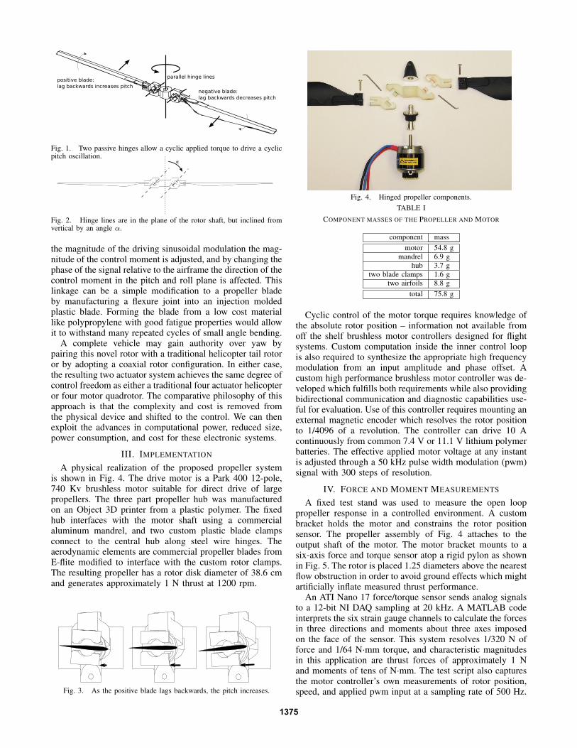
A physical realization of the proposed propeller systemis shown in Fig. 4. The drive motor is a Park 400 12-pole,740 Kv brushless motor suitable for direct drive of largepropellers. The three part propeller hub was manufacturedon an Object 3D printer from a plastic polymer. The fixedhub interfaces with the motor shaft using a commercialaluminum mandrel, and two custom plastic blade clampsconnect to the central hub along steel wire hinges. Theaerodynamic elements are commercial propeller blades fromE-flite modified to interface with the custom rotor clamps.The resulting propeller has a rotor disk diameter of 38.6 cmand generates approximately 1 N thrust at 1200 rpm.
Fig. 3. As the positive blade lags backwards, the pitch increases.
Fig. 4. Hinged propeller components.TABLE I
COMPONENT MASSES OF THE PROPELLER AND MOTOR
component massmotor 54.8 g
mandrel 6.9 ghub 3.7 g
two blade clamps 1.6 gtwo airfoils 8.8 g
total 75.8 g
Cyclic control of the motor torque requires knowledge ofthe absolute rotor position – information not available fromoff the shelf brushless motor controllers designed for flightsystems. Custom computation inside the inner control loopis also required to synthesize the appropriate high frequencymodulation from an input amplitude and phase offset. Acustom high performance brushless motor controller was de-veloped which fulfills both requirements while also providingbidirectional communication and diagnostic capabilities use-ful for evaluation. Use of this controller requires mounting anexternal magnetic encoder which resolves the rotor positionto 1/4096 of a revolution. The controller can drive 10 Acontinuously from common 7.4 V or 11.1 V lithium polymerbatteries. The effective applied motor voltage at any instantis adjusted through a 50 kHz pulse width modulation (pwm)signal with 300 steps of resolution.
IV. FORCE AND MOMENT MEASUREMENTS
A fixed test stand was used to measure the open looppropeller response in a controlled environment. A custombracket holds the motor and constrains the rotor positionsensor. The propeller assembly of Fig. 4 attaches to theoutput shaft of the motor. The motor bracket mounts to asix-axis force and torque sensor atop a rigid pylon as shownin Fig. 5. The rotor is placed 1.25 diameters above the nearestflow obstruction in order to avoid ground effects which mightartificially inflate measured thrust performance.
An ATI Nano 17 force/torque sensor sends analog signalsto a 12-bit NI DAQ sampling at 20 kHz. A MATLAB codeinterprets the six strain gauge channels to calculate the forcesin three directions and moments about three axes imposedon the face of the sensor. This system resolves 1/320 N offorce and 1/64 N·mm torque, and characteristic magnitudesin this application are thrust forces of approximately 1 Nand moments of tens of N·mm. The test script also capturesthe motor controller’s own measurements of rotor position,speed, and applied pwm input at a sampling rate of 500 Hz.
1375
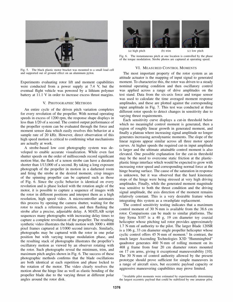
Fig. 5. The black plastic motor bracket was mounted to a small load celland supported out of ground effect on an aluminum pylon.
Experiments evaluating rotor lift and moment capabilitieswere conducted from a power supply at 7.4 V, but theeventual flight vehicle was powered by a lithium polymerbattery at 11.1 V in order to increase excess thrust margins.
V. PHOTOGRAPHIC METHODS
An entire cycle of the driven pitch variation completesfor every revolution of the propeller. With normal operatingspeeds in excess of 1200 rpm, the response shape displays inless than 1/20 of a second. The control output performance ofthe propeller system can be evaluated through the force andmoment sensor data which easily resolves this behavior at asample rate of 20 kHz. However, direct observation of thishigh speed motion is critical to confirming what mechanismsare actually at work.
A strobe-based low cost photography system was de-veloped to enable accurate visualization. While even fastshutter speeds on the order of milliseconds record significantmotion blur, the flash of a xenon strobe can have a durationshorter than 1/13,000 of a second. By taking a long exposurephotograph of the propeller in motion in a darkened roomand firing the strobe at the desired moment, crisp imagesof the spinning propeller can be captured such as thoseof Fig. 6. Since the cyclic behavior is identical on everyrevolution and is phase locked with the rotation angle of themotor, it is possible to capture a sequence of images withthe rotor in different positions and interpret them as a highresolution, high speed video. A microcontroller automatesthis process by opening the camera shutter, waiting for therotor to reach a reference position, and then flashing thestrobe after a precise, adjustable delay. A MATLAB scriptsequences many photographs with increasing delay times tocapture a complete revolution of the propeller. The resultingsynthetic video illustrates the blade motion with 3000 x 4000pixel frames captured at 1/1000 second intervals. Similarly,photographs may be captured with the rotor in one polarposition but with varying torque modulation phase, andthe resulting stack of photographs illustrates the propeller’soscillatory motion as viewed by an observer rotating withthe rotor. Such photographs reveal the minimum, trim, andmaximum pitch angles shown in Fig. 6. The success of thesephotographic methods confirms that the blade oscillationsare both identical at each repetition and phase locked tothe rotation of the motor. The video clearly resolves themotion about the hinge line as well as elastic bending of thepropeller blade due to the varying thrust at different polarangles around the rotor disk.
(a) high pitch (b) trim (c) low pitch
Fig. 6. The instantaneous pitch at one location is controlled by the phaseof the torque modulation. Strobe photos are captured at operating speed.
VI. MEASURED CONTROL MOMENTS
The most important property of the rotor system as anattitude actuator is the mapping of input signal to generatedmoment. To characterize this, the rotor was driven to a steadynominal operating condition and then oscillatory controlwas applied across a range of drive amplitudes on thetest stand. Data from the six-axis force and torque sensorwas used to calculate the time averaged moment responseamplitudes, and these are plotted against the correspondinginput amplitude in Fig. 7. This test was conducted at threedifferent rotor speeds to detect changes in sensitivity due tovarying thrust requirements.
Each sensitivity curve displays a cut-in threshold belowwhich no meaningful control moment is generated, then aregion of roughly linear growth in generated moment, andfinally a plateau where increasing signal amplitude no longergenerates increasing aerodynamic moments. The slope of thelinear regions appear similar across all three motor speedcurves. At higher speeds the required cut-in input amplitudeis larger and the ultimate attainable control moment is alsoelevated. One possible explanation for the cut-in thresholdmay be the need to overcome static friction at the plastic-plastic hinge interface which would be expected to grow withincreasing rotor speed and corresponding normal force at thehinge bearing surface. The cause of the saturation in responseis unknown, but it was observed that the hard kinematicstops of the hinge were being stressed at very high drivingamplitudes. Finally, while the generated moment magnitudewas sensitive to both the thrust condition and the drivingsignal amplitude, the axis direction of the moment remainsrelatively constant. This is a very desirable feature whenintegrating this system as a swashplate replacement.
The control sensitivity testing indicates that a maximumcontrol moment of 30 N·mm is available from the 38.6 cmrotor. Comparisons can be made to similar platforms. Thetiny Syma S107 is a 40 g, 19 cm diameter toy coaxialhelicopter whose pitching tail rotor provides approximately1.7 N·mm of authority to the pilot. The larger Blade 120SRis a 106 g, 33 cm diameter single propeller helicopter whosecyclic control offers 45 N·mm of moment.1 In contrast, themuch larger Ascending Technologies X3D “Hummingbird”quadrotor generates 460 N·mm of rolling moment on its468 g frame from four 20 cm diameter rotors mountedon 17 cm arms, giving it exceptional maneuverability [10].The 30 N·mm of control authority allowed by the presentprototype should prove sufficient for simple maneuvers ina range of aircraft sizes, but eccentric payload capacity oraggressive maneuvering capabilities may prove limited.
1Available pilot moments were estimated by experimentally determiningthe largest eccentric payload that could be stabilized by one amateur pilot.
1376

0 0.05 0.1 0.15 0.2 0.250
5
10
15
20
25
30
35
40Moment Magnitude Mean Response
pulse pwm duty
Mo
me
nt
Ma
gn
itu
de
, N
mm
0.35 pwm duty, avg. 975 rpm
0.40 pwm duty, avg. 1050 rpm
0.45 pwm duty, avg. 1160 rpm
Fig. 7. The net control moment response magnitude increases withincreasing amplitude of excitation.
0 200 400 600 800 1000 1200 14000
0.2
0.4
0.6
0.8
1
1.2
1.4Thrust to RPM
RPM
Th
rust,
N
solid rotor
hinged rotor
Fig. 8. Thrust curve for similar rigid and hinged propellers.
VII. STEADY AERODYNAMIC EFFICIENCY
Achieving useful flight duration is a challenge in MAVsdue to their high power requirements and low capacity for onboard energy storage. Flight efficiency for lifting rotor craft ispredominately dependent on the lift and drag characteristicsof the main rotor. To test whether the new hinged architecturesacrifices thrust efficiency, its performance was comparedto a geometrically similar rigid propeller by measuring liftand drag across a range of rotor speeds as in Fig. 8-9. Oneissue of the new hinged rotor is that in steady state the dragforces bend both blades backwards slightly at their hinges,increasing the angle of attack on one side and decreasingon the other. It is possible to anticipate this degree ofdeflection due to the small range of operating speeds for ahelicopter blade. The rotor blade clamp geometry attempts tocompensate for this effect in for optimal angle of attack in thehover condition, however the lift and drag curve comparisonsshow that rotor performance is distinctly affected.
An important performance metric for lifting rotors is the
0 200 400 600 800 1000 1200 14000
10
20
30
40
50Drag to RPM
RPM
Dra
g,
Nm
m
solid rotor
hinged rotor
Fig. 9. Drag curve for similar rigid and hinged propellers.
0 200 400 600 800 1000 1200 14000
0.2
0.4
0.6
0.8
1
Figure of Merit, Pid
/Pmeas
RPM
Me
rit
solid rotor
hinged rotor
Fig. 10. Figure of merit for geometrically similar hinged and rigid hubpropellers.
figure of merit, FM , defined as the ideal power divided bythe actuator power for a given thrust and incident flow ve-locity. The actuator mechanical shaft power on the test standPmeas is given by the product of the applied torque M andthe rotor shaft speed w. The ideal power Pid is derived frommomentum theory by solving for the momentum balance in acontrol volume around the idealized actuator disk. The idealpower at hover is dependent on the thrust T , air density ρ,and rotor radius r, and this value is used to calculate FMaccording to equations 1-3 [11].
Pmeas =M ∗ w (1)
Pid =T
32√
2ρπr2(2)
FM =Pid
Pmeas(3)
FM for both the hinged propeller system and the ge-ometrically similar fixed hub propeller are compared inFig. 10. The hover efficiency of the hinged blade sampleis slightly worse than its fixed hub counterpart over most ofthe operational envelope. This performance analysis suggeststhat the amount of blade trim adjustment due to drag has beenincorrectly estimated in this iteration, and the angle of attackin steady state does not reach its optimum configuration.Future iterations of the zero-deflection angle pitch for theblade clamps will be informed by these results.
VIII. STEADY CYCLIC RESPONSE
The time history of moment response over each rotorrevolution was measured in response to a driving oscillatoryinput voltage amplitude of 0.10 pwm about a mean valueof 0.35 pwm duty factor, corresponding to a rotor speedof 931 rpm on a 7.4 V power supply. Fig. 11 shows themeasured vertical axial torque applied to the rotor in black,the moment about the horizontal axis of maximum meanresponse in blue, and the moment about the horizontaltransverse axis in red. In a flight system, a roll responsewould be directed by aligning the axis of maximum meanresponse with the roll axis of the airframe. Dotted trendlines show the long term average moment about the excitedaxis is 14.6 N·mm, and the average moment about thetransverse axis is nearly zero. During these tests a steadyonce per revolution oscillation in moment was also observeddue to dynamic and aerodynamic imbalance in the rotor.This component did not contribute to the mean values of
1377

1000 1020 1040 1060 1080 1100 1120 1140 1160 1180 1200−100
−50
0
50
100Pitch and Roll Moments
time, ms
mo
me
nt,
Nm
m
drive torque
excited axis
transverse axis
Fig. 11. Cyclic torque and response moment at 1192 rpm with 0.09 pwmduty excitation amplitude. Bars highlight the period of revolution.
1000 1020 1040 1060 1080 1100 1120 1140 1160 1180 1200−100
−50
0
50
100
Pitch and Roll MomentsLow Pass Filtered
time, ms
mo
me
nt,
Nm
m
drive torque
excited axis
transverse axis
Fig. 12. Low-pass filtered cyclic torque and response moment at 1192 rpmwith 0.09 pwm excitation amplitude. Bars highlight the period of revolution.
the control response and was subtracted out to highlight thecharacteristic twice-per-revolution behavior in these figures.The motor’s cogging torque ripple is also represented in boththe axial driving torque and the response moments. In Fig. 12the signals have been post processed with a bidirectional firstorder Butterworth low pass filter. The filter corner frequencywas placed at 12 times the rotor speed in order to attenuatethe lowest frequency cogging ripples by -3 db.
The low pass filtered results highlight the expected fre-quency doubling property of the propeller system, with peaksin the excitation moment corresponding to the passing ofeach of the two rotor blades. Major and minor peaks indicatethat the two propeller blades are not contributing equallyto the long term output moment, which suggests the blademotions are not equally sensitive to changing applied torques.Adjusting the hinge-neutral blade pitch on each side maypartially alleviate this asymmetry in future iterations.
IX. TRANSIENT RESPONSE TO STEP INPUTS
A practical implementation of the hinged propeller systemin a free flight craft requires rapid changes in commandedorienting moment magnitudes and directions. As a result,the transient response to fluctuating torque inputs is just asimportant as the steady state response sensitivities previouslysummarized in Fig. 7. The response to step inputs are a goodindication of this type of performance. Figs. 13-14 showthe raw moment measurements associated with a series ofsteps in control input at a propeller velocity of 1192 rpm.When active, the driving torque traces a sinusoidal historyand the orthogonal x and y axes reveal twice per revolutionoscillations as each blade passes. The background once perrevolution oscillation observed even when the modulation isnot active is due to an undesirable imbalance in the rotor.
The initial commanded moment is zero with zero inputoscillation, at t = 1 s the input oscillation amplitude steps
0.5 1 1.5 2 2.5−100
−50
0
50
100Pitch and Roll Moments
time, s
mom
ent, N
mm
drive torque
x axis moment
y axis moment
Fig. 13. Three switching events in magnitude and phase.
850 900 950 1000 1050 1100 1150−100
−50
0
50
100Pitch and Roll Moments
time, ms
mo
me
nt,
Nm
m
drive torque
x axis moment
y axis moment
Fig. 14. Highlight of step in modulation amplitude.
to 0.10 pwm duty to command a moment about one axis,at t = 1.5 s the phase of input oscillation steps by 180o tocommand a reversal in orienting moment direction, and att = 2 s the commanded moment returns to zero. At eachstage the output response waveform settled into the newdriven limit cycle within one revolution of the propeller,consistent with a step input rise time of less than 50 ms.This level of performance is comparable to cyclic controlhelicopter craft which generate body moments through pitchreorientation in a very similar way to the proposed hingedpropeller system. Quadrotor systems, on the other hand, mustgenerate variations in body moment by changing the thrust ofeach propeller. This ramp in thrust has been characterized forthe popular Ascending Technologies X3D “Hummingbird”quadrotor as a first order linear process with a rise timeof 44 ms for rising and 88 ms for falling inputs [10].Others have attempted to improve on this benchmark byaugmenting the quadrotor with collective pitch actuators andhave achieved similar rise and fall times of 40 ms [3]. In thislight, the capacity for arbitrary moment modifications withina single propeller revolution makes the hinged rotor conceptcompetitive with widely adopted MAV technologies.
X. FLIGHT SYSTEM DESIGN AND TESTING
A complete MAV system was developed to demonstratehow this novel rotor can be successfully incorporated intoan airframe, shown in Fig. 15. The MAV adopts a coaxialrotor configuration with a standard fixed pitch propelleron the bottom and the underactuated hinged rotor on top.The vehicle has no passive stability due to the lack of thetraditional flybar mechanism. No servo-driven swashplate,auxiliary pusher propellers, or thrust vectoring techniques areemployed – the stability and controllability of the vehicle aredue exclusively to the dynamic response of the top propellerto the electronic modulation of the main rotor torque. Thefinal aircraft supports a 30 cm diameter bottom rotor and a
1378
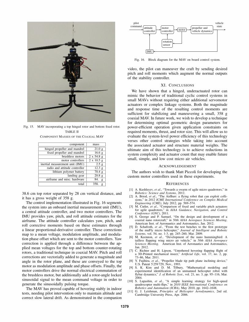
Fig. 15. MAV incorporating a top hinged rotor and bottom fixed rotor.
TABLE IICOMPONENT MASSES OF THE COAXIAL MAV
component masshinged propeller and mandrel 21.0 g
fixed propeller and mandrel 16.6 gbrushless motors 2 x 54.8 gmotor controllers 2 x 10.5 g
inertial measurement unit (IMU) 2.5 gradio and attitude controller 12.3 g
lithium polymer battery 70.4 glanding gear 20.8 g
airframe and misc. hardware 84. gtotal 358. g
38.6 cm top rotor separated by 28 cm vertical distance, andit has a gross weight of 358 g.
The control implementation illustrated in Fig. 16 segmentsthe system into an onboard inertial measurement unit (IMU),a central attitude controller, and two motor controllers. TheIMU provides yaw, pitch, and roll attitude estimates for theairframe. The attitude controller calculates yaw, pitch, androll corrective moments based on these estimates througha linear proportional-derivative controller. These correctionsmap to a mean voltage, modulation amplitude, and modula-tion phase offset which are sent to the motor controllers. Yawcorrection is applied through a difference between the ap-plied mean voltages for the top and bottom counter-rotatingrotors, a traditional technique in coaxial MAV. Pitch and rollcorrections are vectorially added to generate a magnitude andangle in the rotor plane, and these are conveyed to the topmotor as modulation amplitude and phase offsets. Finally, themotor controllers drive the normal electrical commutation ofthe brushless motor, but additionally add a rotor-angle lockedsinusoidal signal to the mean command voltage in order togenerate the sinusoidally pulsing torque.
The MAV has proved capable of hovering stably in indoortests, needing pilot intervention only to maintain altitude andcorrect slow lateral drift. As demonstrated in the companion
attitudecontroller
motorcontroller
motorpropeller andvehicle dynamics
rotationsensor
IMU
pilotcommand
vehiclestate
Fig. 16. Block diagram for the MAV on board control system.
video, the pilot can maneuver the craft by sending desiredpitch and roll moments which augment the normal outputsof the stability controller.
XI. CONCLUSIONS
We have shown that a hinged, underactuated rotor canmimic the behavior of traditional cyclic control systems insmall MAVs without requiring either additional servomotoractuators or complex linkage systems. Both the magnitudeand response time of the resulting control moments aresufficient for stabilizing and maneuvering a small, 358 gcoaxial MAV. In future work, we wish to develop a techniquefor determining optimal geometric design parameters forpower-efficient operation given application constraints onrequired moments, thrust, and rotor size. This will allow us toevaluate the system-level power efficiency of this technologyverses other control strategies while taking into accountthe associated actuator and structure material weights. Theultimate aim of this technology is to achieve reductions insystem complexity and actuator count that may enable futuresmall, simple, and low cost micro air vehicles.
ACKNOWLEDGEMENT
The authors wish to thank Matt Piccoli for developing thecustom motor controllers used in these experiments.
REFERENCES
[1] A. Kushleyev, et al., “Towards a swarm of agile micro quadrotors,” inRobotics: Science and Systems, 2012.
[2] A. Briod, et al., “The AirBurr: a flying robot that can exploit colli-sions,” in 2012 ICME International Conference on Complex MedicalEngineering (CME), July 2012, pp. 569–574.
[3] M. Cutler, et al., “Comparison of fixed and variable pitch actuatorsfor agile quadrotors,” in AIAA Guidance, Navigation, and ControlConference (GNC), 2011.
[4] S. George and P. Samuel, “On the design and development of acoaxial nano rotorcraft,” in 50th AIAA Aerospace Sciences Meeting.American Inst. of Aeronautics and Astronautics, Jan. 2012.
[5] D. Schafroth, et al., “From the test benches to the first prototypeof the muFly micro helicopter,” Journal of Intelligent and RoboticSystems, vol. 54, no. 1-3, pp. 245–260, Mar. 2009.
[6] M. Keennon, et al., “Development of the nano hummingbird: Atailless flapping wing micro air vehicle,” in 50th AIAA AerospaceSciences Meeting. American Inst. of Aeronautics and Astronautics,Jan. 2012.
[7] C. Richter and H. Lipson, “Untethered hovering flapping flight ofa 3D-Printed mechanical insect,” Artificial Life, vol. 17, no. 2, pp.73–86, Mar. 2011.
[8] Y. Fujihira, et al., “Propeller blade tip path plane inclining device,”U.S. Patent 5 259 729, Nov., 1993.
[9] S. K. Kim and D. M. Tilbury, “Mathematical modeling andexperimental identification of an unmanned helicopter robot withflybar dynamics,” J. of Robotic Syst., vol. 21, no. 3, pp. 95–116, Mar.2004.
[10] S. Lupashin, et al., “A simple learning strategy for high-speedquadrocopter multi-flips,” in 2010 IEEE International Conference onRobotics and Automation (ICRA), May 2010, pp. 1642–1648.
[11] G. J. Leishman, Principles of Helicopter Aerodynamics, 2nd ed.Cambridge University Press, Apr. 2006.
1379