AN ULTIMATE STRENGTH DESIGN PROCEDURE FOR … · AN ULTIMATE STRENGTH DESIGN PROCEDURE FOR CIAY...
12
AN ULTIMATE STRENGTH DESIGN PROCEDURE FOR CIAY BRICK MASORRY SBEAR 1fALLS Trevo r E Kelly l, Dr Ronald L Mayes 1 , Dr Masoud Moghtaderi-Zadeh 2 lComputech Engineering Services, Inc. Berkeley, California, USA. 2Intevep, S.A., Apartado 76343, Caracas-1070A, Venezuela ABSTRACT This paper presents the basis for an ultimate strength design procedure for clay brick masonry walls. The procedure is rationally based on ultimate strength design considerations and provides a basis for both shear and flexural designo The problem is formulated in probabilistic terms and accounts for uncertainties in factors such as workmanship, test results , mathematical modelling, structural properties (damping and ductility), earthquake intensity and wind forces. Best currently available estimates of wall strength and wind and earthquake induced for ce s are incorporated into the method. Modifications to the procedure can easily be accomplished as these best estimates change as a result of future research. An example of the incorporation of strength formulas into future codes is presented. 1 IRTROI>1JCl'ION Current design procedures for masonry in the United States are based on working stress procec.lures, e. g. Uni form Building Code (UBC) [1]. In this respect reinforced masonry lags behind reinforced concrete where the ultimate strength theory for design was adopted in 1956. In large part this reflects the more limited available experimen tal data for masonry than for co ncrete. However in the pa st decade maso nry research activity has increased substantially especially in the field of lateral load resistance of masonry shear walls. Sufficient data has been collected to enable the development of an ultimate stre ngth design pr oc edure for use in the design processo The use of an ultimate streng th procedure all ows the rational selection of load factors to provide the requi r ed degree of reliahility. Also, in seismic regions the specified loads for eat"thquakes are con siderably less than the elastic load which the wall is likely to experience in its lifetime . The co de load coefficients assume a ductile response. The use of ultimate strength procedures allows this ductility to be quantified and the load f actors adjusted depending on the ductility available. This paper describes the development of appropriate load factors and strength co mplltatj on s for both shear and flexure in masonry walls. Lateral loads arising from earthquakes and from wind have been considered. Modern probabilistic methods and structuraJ reliahility concepts have been utilized in order to account for the uncertainties in the design and construction of masonry shear walls, the loads to which they are subjected and the available test results. A detailed discussion of the con cepts and procedures is given in References 2 and 3. The main points of the pr o cedure are briefly discussed here. 2 DEVELOPMEN"I" OF TBE S'l'REJ.IfGTH DESIGR PROCEDURE The ultimate strength design procedure must be developed in such a way that the uncertainties in alI variables which affect the performance of the wall during its useful lifetime are taken into account. Therefore the determination of the ultimate strength equation must be formulated in a probabilistic sense. A 1185
Transcript of AN ULTIMATE STRENGTH DESIGN PROCEDURE FOR … · AN ULTIMATE STRENGTH DESIGN PROCEDURE FOR CIAY...

AN ULTIMATE STRENGTH DESIGN PROCEDURE FOR
CIAY BRICK MASORRY SBEAR 1fALLS
Trevor E Kelly l, Dr Ronald L Mayes 1 , Dr Masoud Moghtaderi-Zadeh 2
lComputech Engineering Services, Inc. Berkeley, California, USA. 2Intevep, S.A., Apartado 76343, Caracas-1070A, Venezuela
ABSTRACT This paper presents the basis for an ultimate strength design procedure for clay brick masonry walls. The procedure is rationally based on ultimate strength design considerations and provides a basis for both shear and flexural designo The problem is formulated in probabilistic terms and accounts for uncertainties in factors such as workmanship, test results , mathematical modelling, structural properties (damping and ductility), earthquake intensity and wind forces. Best currently available estimates of wall strength and wind and earthquake induced forces are incorporated into the method. Modifications to the procedure can easily be accomplished as these best estimates change as a result of future research. An example of the incorporation of strength formulas into future codes is presented.
1 IRTROI>1JCl'ION
Current design procedures for masonry in the United States are based on working stress procec.lures, e. g. Uni form Building Code (UBC) [1]. In this respect reinforced masonry lags behind reinforced concrete where the ultimate strength theory for design was adopted in 1956. In large part this reflects the more limited available experimental data for masonry than for concrete.
However in the past decade masonry research activity has increased substantially especially in the field of lateral load resistance of masonry shear walls. Sufficient data has been collected to enable the development of an ultimate strength design procedure for use in the design processo The use of an ultimate strength procedure allows the rational selection of load factors to provide the requi r ed degree of reliahility. Also, in seismic regions the specified loads for eat"thquakes are considerably less than the elastic load which the wall is likely to experience in its lifetime . The code load coefficients assume a ductile response. The use o f ultimate strength procedures allows this ductility to be quantified and the load f actors adjusted depending on the ductility available.
This paper describes the development of appropriate load factors and strength c omplltatj ons for both shear and flexure in masonry walls. Lateral loads arising from earthquakes and from wind have been considered. Modern probabilistic methods and structuraJ reliahility concepts have been utilized in order to account for the uncertainties in the design and construction of masonry shear walls, the loads to which they are subjected and the available test results. A detailed discussion o f the concepts and procedures is given in References 2 and 3 . The main points of the pro cedure are briefly discussed here.
2 DEVELOPMEN"I" OF TBE S'l'REJ.IfGTH DESIGR PROCEDURE
The ultimate strength design procedure must be developed in such a way that the uncertainties in alI variables which affect the performance of the wall during its useful lifetime are taken into account. Therefore the determination of the ultimate strength equation must be formulated in a probabilistic sense. A
1185

schematic flow chart of the methodology to develop the design strength equation is shown in Figure 1.
The methodology involves the following steps:
1. Selection of an appropriate formula and load factors to be used for the calculation of the design earthquake force.
2. Selection of an appropriate equation to be used for the calculation of the ultimate strength of the shear wall.
3. Prediction of the maximum expected earthquake force in a probabilistic sense.
4. Prediction of the uI timate strength of a shear wall in a probabilistic sense.
5. Calculation of a proper reliability measure. 6. Comparison of the calculated reliabili ty measure vs. society' s
acceptable leveI of safety.
step 5 involves the definition of a proper reliability measure. Following modern probabilistic methods and structural reliability concepts, the safety of the wall in each failure mode may be expressed in terms of a performance function:
Z = R - S . . . ( 1 )
where R is the ultimate shear or flexural strength and S is the maximum expected earthquake load. The random variables R and Sare functions of other basic random variables. Failure will occur when {Z<O}i i.e., when the applied load is greater than corresponding ultimate strength of the wall. The reliability index of Z, denoted e, is defined as [4,5,6,7]:
. . . . . ( 2 )
where Z and o are the mean and standard deviation of random variable Z,
respectively. ~e probability of failure is closely related to this reliability indexo Using the mean-value first-order second-moment (MVFOSM) method of reliability analysis, closed form solutions may be obtained for load and resistance factors for given values of e. In order to avoid inconsistencies in the determination of the reliability index, The Hasofer-Lind algorithm [6] is used. Values for the reliability index consistent with current practice are 1.75 for seismic design and 2.5 for wind design (5).
3 DETERMIRATION OF LOADS ARO STRERG'l'BS
The development of the ultimate strength procedure requires determination of the des i gn strength and load (deterministic ) and the maximum expected strength and load (probabilistic ). The means used to obtai n these values are described fully in References 2 and 3 and brie fly in t he f Ollowing sections .
3 . 1 Design Loads 3 . 1.1 Earthguake
The 1982 UBC [1] specifies the earthquake loads as the following:
v = Co (ZICSK) Wd
. . ( 3 )
where Z is a zone factor, I and importance factor, S a soil type factor and K the structural type factor. C is the basic design coefficient and is a function of the period of the structure. The coefficient C is generally 1.0 but is used
o
1186
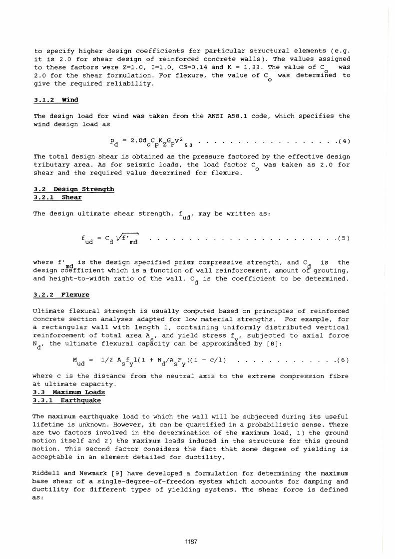
to specify higher design coefficients for particular structural e1ements (e.g. it is 2.0 for shear design of reinforced concrete walls). The values assigned to these factors were Z=1.0, I=1.0, CS=0 . 14 and K = 1.33. The value of C was 2. O for the shear formulation. For f1exure, the value of C was determiged to
o give the required reliability.
3.1.2 Wind
The design load for wind was taken from the ANSI A58.1 code, which specifies the wind design load as
Pd = 2.0doCpKZGpV250 .................. (4)
The total design shear is obtained as the pressure factored by the effective design tributary area. As for seismic loads, the load factor C was taken as 2.0 for
o shear and the required value determined for flexure.
3.2 Design Strength 3.2.1 Shear
The design ultimate shear strength, fUd' may be written as:
. ( 5 )
where f' d is the design specified prism compressive strength, and C is the design c~efficient which is a function of wall reinforcement, amount of grouting, and height-to-width ratio of the wall. C
d is the coefficient to be determined.
3.2.2 Flexure
Ultimate flexural strength is usually computed based on principIes of reinforced c oncrete section analyses adapted for low material strengths. For examp1e, for a rectangular wall with 1ength 1 , containing uniformly distributed vertical re in f o rcement of t otal area A , and y ie1d stress f , subjected to axial force N
d, the u ltimate flexural cap~city c an be approximáted by [8] :
M = ud
1/2 A f 1 ( 1 + Nd/A F )(1 - c/I ) s Y s Y
. . . . . . . . ( 6 )
where c i s t he distance f r om t he neut ral axi s t o the extreme c ompression fibre at ultimate capacity . 3.3 Maximum Loads 3.3.1 Earthquake
The maximum earthquake 10ad to which the wal1 will be subjected during its useful 1ifetime is unknown. However, it can be quantified in a probabi1istic sense. There are two factors involved in the determination of the maximum load, 1) the ground motion itself and 2) the maximum loads induced in the structure for this ground motion . This second factor considers the fact that some degree of yielding is acceptable in an element detailed for ductility.
Riddell and Newmark [9] have deve10ped a formu1ation for determining the maximum base shear of a single-degree-of-freedom system which accounts for damping and ductility for different types of yielding systems. The shear force is defined as:
1187
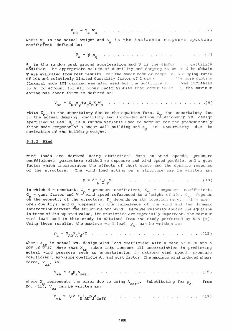
v = S W '. / ) sa a a
where W is the actual weight and S is th e ine lasti c r es pon >-e sp e ctrum coeffic~ent, defined as: a
S a
A is the random peak ground acc elerat i o n and 7/f is t he damI' ir -m2difier. The appropriate values o f d uct i l i ty and damping t o bR
. ( 8 )
ulI.ct i l ity r: ·/1 to obtain
'VI' are evaluated from test results . For the shear mode of .resr" e o" I." ,o.,pi ng ratio of 10% and relatively limited duct i lity factor of 2 war> I ' • " e lüúre ductl '_ .~
flexural mode 10% damping was a l s o used but the ~uct _~ .J. Ly L
to 4. To account for alI other unc e r t aint i es that occur i l, i: 1 earthquake shear force is defined as :
v = X X 'l'A X. X W sa MS 'VI' 9 b D d
was i ncreased " the max imum
. ( 9 )
where XMS
is the uncertainty due t o the e quation f o rm, X the unc e r tai nty due to the actual damping, ductility and fo rce-deflection rtla tionship vs . des i g n specified values. ~ is a random variable used to account for the predominantly first mode response of a shear wal l building and X is uncertaint y due to estimation of the building we i ght. D
3.3.2 Wind
Wind loads are derived using statistical data o n wind s p eeds, pressure coefficients, parameters related to exposure and wind speed profile, and a gust factor which incorporates the effects of short gust s and the dynar-.~oc response of the structure . The wind load act ing on a structure may be ,,·ritten as:
p de K G v2 P Z P
. ( 10)
in which d = constant, e pressur e c oefficient, K exposure c uefficie nt, G = gust factor and V =Pwind speed r eferenced to aZheigh t o f 10 . .'1 . c: c' epend8 o~ the geometry of the struct ure , K depends on its location (e. g ., l ',b;' n are. open country), and G depends on t~e t urbulence o f f:he wind and the dynamic interaction between the structure a nd wi nd . Because veloci ty enters the e q uat ion in terms of its squared value , i t s stat i s t ics are especially important. The maximum wind load used in this study i s obtained Erom the study performed b y NBS [5]. Using these results, the maximum wind l oad , Pa' can b e written a s:
p = X X Pd/2 a AO A · ( 11 )
where X is actual vs. design wind load coefficient with a me a n of 0 .78 and a eov of ~37. Note that X takes into account alI uncer t aint ies i n predicting actual wind pressure su~ as uncertai nties i n extreme wi nd spee d, pres sure coefficient, exposure coefficient, and gust fac to r . The maxi mum wi nd induced s hear force, V , is:
wa
where X represents the error due to using Adeff
. Substituting fo r Pa Eq. (11~, V can be written as:
wa
v wa
1188
· ( 12 )
from
· ( 13 )

3.4 Maxiaum Strength 3.4.1 Shear
The actual ultimate shear capacity of masonry shear walls, V " must include the uncertainties due to (a) workmanship, (b) actual vs~aspecified prism compressive strength (c) shear strength observed in tests and (d) appropriateness of formula for predicting the shear strength .
The actual ultimate shear capacity of the wall as constructed is obtained as:
v ' V = X A C X f' ua A dXJCMR T f md · ( 14)
in which X is uncertainty due to the actual size vs. the design size of the wa1l, X tfte uncertainty due to workmanship, and ~ uncertainty due to model error, !. e ., defining shear strength as a function of ~ . C is a random
m T variable defining the shear strength coefficient whose variation is obtained from the test results, based on the performance criteria that the wall may be cracked but must be capable of retaining its vertical load carrying capacity. X
f is
the uncertainty due to the actual vs. design value of f' . m
3.4.2 P'lexure
From limited number of tests available, the actual ultimate flexural capacity of a wall, Mua' is related to its design value, MUd' according to:
M ua X M d T u
· (14)
where X is a random variable with known mean and COV obtained from tests with controlIed workmanship and known axial load. Hence the actual ultimate flexural capacity may be different due to a better or worse workmanship vs . that of the tests or due to actual axial load, N , vs. design specified N
d, or due to
actual size of the wall. Therefore, A may be now rewritten as: ua
M ua · ( 15 )
where ~, X , and X are included to account for uncertainties in workmanship, axial load ~nd sizeAof the wall. The random variable X representing the uncertainty in axial load is composed of two parts: un~ertainty in dead load, and uncertainty in structural analysis leading to its computation. Therefore X
N may be written as:
· (16)
where Xo and XN1
represent uncertainties in dead load and structural analysis, respectlvely. For cantilever walls, the random variable X
N1 has a mean 1.0
and COV of 0.0.
4 COIIPOTATIOR OF RELIABILI'l"Y nmEX
Following the concepts of structural reliability, the safety of a structure in its i-th failure mode is expressed in terms of a performance function:
z . 1
. X ) n · (17)
were c . ' sare deterministic parameters and X . ' sare basic random variables which affect
1the performance of the structure in its J.i-th mode. This function is usually
1189
formulated such that {Z. < O} implies failure and {Z. > O} implies survival of the structure in its i-€h mode of failure. 1
In the following derivation the shear mode of failure under seismic loading is considered as an example of the procedure. One way to formulate g(.) for this problem is:
Z = V - V ua sa
. . . . (18)
That is, failure {Z < O} will occur when the earthquake shear force exceeds the actual shear force capacity of the wall, or
Z = [~ XAVMRCT Vxf - XMSX.,'1'Ag~XO)Wd . . . . . . . . . . . . (19) d
or dividing both sides by Wd
and redefine Z by:
~ XAVMRCT~ - ~X .... '1'A ~XO d ~ 9
Z = . • • . (20)
Note that Z is also a random variable. The probability of failure of the wall in the shear mode of failure is related to the mean and standard deviation of this random variable. The reliability index of Z (denoted /3 as defined in Eqn. 2) is often viewed as the probabilistic counterpart of the conventional term "factor of safety."
AlI terms in Eq. (19) are defined except C which can be obtained so that the shear wall will have a specified reliabili~y leveI. A closed form solution was obtained for Cd in terms of /3 and the means and coefficients of variation of the other individual random variables. This was performed using the mean-value firstorder second-moment (MVFOSM) method of reliability analysis. To overcome a problem of "lack of invariance" in the MVFOSM method, Hasofer and Lind (6) proposed a new definition of reliability index, /3HL' A computer program based on the Hasofer-Lind method was developed to determine C
d for a given value of the
reliability indexo
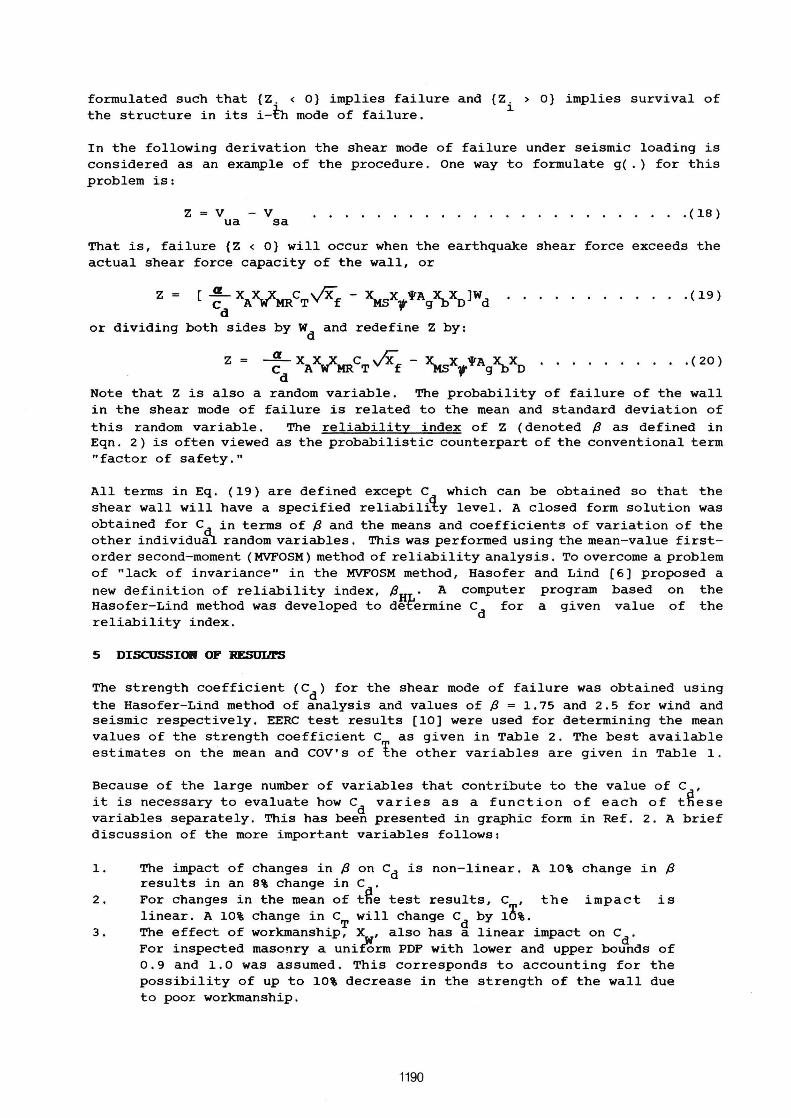
5 DISCUSSICXII OF RE5UIl1'S
The strength coefficient (Cd
) for the shear mode of failure was obtained using the Hasofer-Lind method of analysis and values of /3 = 1.75 and 2.5 for wind and seismic respectively. EERC test results [10) were used for determining the mean values of the strength coefficient C as given in Table 2. The best available estimates on the mean and COV's of ~he other variables are given in Table 1.
Because of the large number of variables that contribute to the value of Cd
' it is necessary to evaluate how C
d varies as a function of each of tfiese
variables separately. This has been presented in graphic form in Ref. 2 . A brief discussion of the more important variables follows:
1.
2.
3.
The impact of changes in /3 on Cd is non-linear. A 10% change in /3 results in an 8% change in C . For changes in the mean of tRe test results, C, the impact is linear. A 10% change in C will change C
d by 10%.
The effect of workmanShiP; X , also has a linear impact on cd
. For inspected masonry a uni~rm POF with lower and upper bounds of 0.9 and 1.0 was assumed. This corresponds to accounting for the possibility of up to 10% decrease in the strength of the wall due to poor workmanship.
1190

4.
5.
The uncertainty in f' is represented by Xf
with a mean of 1.25 and a COV of 0.20. The im~act of X on C
d is less pronounced than other
variables due to Xf
being in ~quare root form in the performance function. C has a highly non-linear variation with the mean of A . Hgwever, care must be exercised since as A decreases gfor lower seismic areas, the zone factor, Z, of thegUBC also decreases. For the analysis, a Z-factor of 1 and an A of 0.24g was selected to be representative of the Los Angeles are a?
For the variables given in Table 1, the corresponding values of C are given in Table 3 . The benefit of the procedure is that the impact of c%anges in any of the variables can easily be evaluated. One of the major decision are as is the utilization of the ultimate strength design procedure is the load factor, C . A value of C of 2.0 was used herein, however, the ANSr AS8.1 1982 foad provisions rgcommend a value of 1.5. rf this ·were adopted, the appropriate values of C d would be 0.75 times the values given in Table 3. rf a «1> factor were incorporated in the procedure, the values given in Table 3 would be increased by 1/«1> since C
d has been calculated such that alI the uncertainties have been
accounted for.
The load factor, C , for the flexural mode of failure was also obtained using o
the Hasofer-Lind method and P values of 1.75 and 2.5. Values of other variables are given in Table 1. A value of X = 1.0 with a COV of O was used, implying that a cantilever wall was assumed~lAs with shear, the impact of variations in alI the variables was evaluated and presented in graphic form in Ref. 2. For the values given in Table 1, a load factor, C , of 1.45 was obtained for seismic and 1.52 for wind. Thus, if a load factor of 1~5 as recommended by ANsr A58.1, 1982, is used, walls designed for flexure will perform adequately provided a shear failure is prevented.
6 EXAIIPLE DF CODE APPLIeM."IOII
The Structural Engineers' Association of California (SEAOC) is currently revising their seismic design provisions, which form part of the UBC code. As part of this revision a draft masonry design section has been prepared which includes both working stress and ultimate strength methods of designo
The specification of the design load in the SEAOC revision will differ from that of the UBC in that a maximum credible earthquake coefficient will be specified rather than a reduced value as in the current code. This maximum load will be reduced by a response modification factor (R) which is a function of structural type and material.
The maximum seismic coefficient for the proposed revision is 1.0 which is then reduced by the R factor. From the procedures presented here, the re1iabi1ity index appropriate for seismic loads may be achieved using a load factor of 1.45 on the current UBC load, i.e. 1.45 (ZrCSK) (Eqn. 3). Using the values of these variables listed in Section 3.1.1 this provides for a flexural coefficient of 1 . 45xO.186=0.27. As the ultimate strength procedure provides for a «1> facto r of 0.85, this corresponds to a specified coefficient of (0.27xO.85) = 0.23. An appropriate R factor would then be 1/0.23=4.4. For consistency with other structural types and materiaIs a basic R factor of 5 was used. This applies only to high cantilever walls without significant openings. For other wall configurations a wall type coefficient is used to increase the design load so that the effective R value ranges from 5 to 1.25.
1191

For shear design, the draft code requires an increase over the design force used for flexure by use of capacity design procedures and a lower ct> factor . The maximum R factor for shear is (5xO. 85/1. 3 )=3.3. This is then used with a ct> factor of 0.65 to give an effective design coefficient in terms of this procedure of 1.0/(3.3xO.65)=0.47. Therefore, the C
d values given in Table 3 can be
factored by (0.47/0.372)=1.265 to obtain design coefficients in terms of the loading specified in the design code. A comparison of the factored values and the draft code values is as follows:
Ultimate Strength procedures (Table 3 )
Factored by 1.265
Draft Code Values
7 CORCLDSIORS
LIGHT REINFORCING M/VdÕ!!l. O M/Vd~O. 25
2.7 3.9
3.4 4.9
2.5 4.5
HEAVY REINFORCING M/VdÕ!!l.O M/Vd~0.25
3.1 5.0
3.9 6.3
3.5 6.0
A formulation to provide a basis for the ultimate strength design procedure for clay brick masonry shear wall buildings has been presented. This procedure has been developed using probabilistic concepts considering both the shear and flexural modes of failure. The benefit of the method developed is that changes in any of the variables incorporated in the formulation can easily be evaluated. This will permit a continuing evaluation of the procedure as updated research data comes to hand.
This study was funded by the Western States Clay products Association and their financiaI and technical support throughout the duration of the project is gratefully acknowledged.
9 REf'ERElilCES
1. "Uniform Building Code," 60th Anniversary Edition, International Conference of Building Officials, Whittier, Calif., 1982.
2. Moghtaderi-Zadeh M., and Mayes, R.L., "Development of Ultimate Strength seismic and Wind Design Procedures for Clay Brick Masonry Shear Walls, " Report to CES, Computech Engineering Services, Inc., Berkeley, CA., December 1982.
3. Moghtaderi-Zadeh, M., Mayes, R.L., and Sveinsson, B.r., "Ultimate Strength Design procedure of Masonry Walls for Lateral Forces", Proceedings, 8th World Conference for Earthquake Engineering, San Francisco, 1984.
4. E1lingwood, B. R., and Ang, A. H-S., "Risk-Based Evaluation of Design Criteria," Journal of the Structural Division, ASCE, Vol. 100, No. ST9, Proc. Paper 10778, Sept., 1974, pp. 1771-1788.
1192

5. Ellingwood, B . R., Galambos, T. V., MacGregor, J. G., and Cornell, C .A. , "Development of a Probabilty Based Load Criterion for Arnerican National Standard A58," NBS Special Publication 577, U. S. Department of CommercejNational Bureau of Standards, Washington, D.C., June, 1980.
6. Hasofer, A . M. , Code Format," ASCE, VoI. 100,
and Lind, N.C ., "Exact and Invariant Second-Moment Journal of the Enqineerinq Mechanics Division, No. EMl, Proc . Paper 10376, Feb., 1974, pp. 111-121 .
7. Kitagawa, M., and Der Kiureghian, A., "Safety Index by First-Order Second-Moment Reliability Method," Report No. UCB/SESM-80109, Division of Structural Engineering and structural Mechanics, Department of Civil Engineering, University of California, Berkeley, Calif., Dec., 1980.
8 . Cardenas, A.E., Hanson, J.H., Corley, W.G., and Hognestad, E., "Design Provisions for Shear Walls," Journal of the Arnerican Concrete Institute, Proceedings.
9 . Riddell, R., and Newmark, N .M., "Statistical Analysis of the Response of Nonlinear systems Subjected to Earthquakes," Report No. UILU 79-2016, Department of Civil Engineering, University of Illinois, Urbana, 111 . , August, 1979.
10 . Sveinsson, B., Mayes, R.L., and McNiven,H . D., "Evaluation of Seismic Design Provisions for Masonry in the United States," Report No. UCB/EERC-81/10, Earthquake Engineering Research Center, University of California, Berkeley, Calif . , August, 1981.
1193
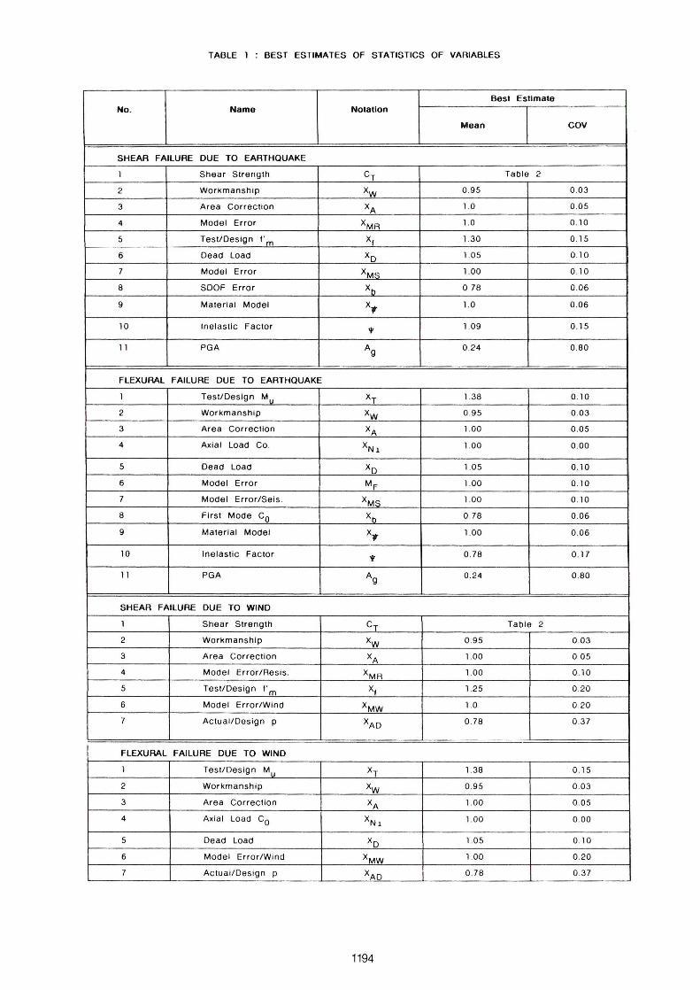
TABLE 1 BEST ESTIMATES OF STATISTICS OF VARIABLES
SesI Eslimale No. Name NOlallon
Mean COV
SHEAR FAILURE DUE TO EARTHQUAKE
1 Shear Strength CT Table 2
2 Workmanship Xw 0.95 0.03
3 Area Correction XA 1.0 0 .05
4 Model Error XMA 1.0 0 .10
5 TestlDesign f" m Xf 1.30 0 .15
6 Oead Load Xo 1.05 0. 10
7 Model Error XMS 1.00 0 .10
8 SDOF Error Xb
0.78 0.06
9 Material Model X., 1.0 0.06
10 Inelastlc Factor
'" 1.09 0.15
11 PGA Ag 0.24 0 .80
FLEXURAL FAILURE DUE TO EARTHQUAKE
1 TestlOeslgn Mu XT 1.38 0. 10
2 Workmansh ip Xw 0.95 0 .03
3 Area Correctlon XA 1.00 0 .05
4 Axial Load Co . XN1 1.00 0.00
5 Dead Load XD 1.05 0.10
6 Model Error MF 1.00 0 .10
7 Model Error/Seis . XMS 1.00 0 .10
8 First Mode Co Xb 0.78 0.06
9 Material MOdel X., 1.00 0 .06
10 Inelastic Factor
'" 0 .78 0 .17
11 PGA Ag 0.24 0 .80
SHEAR FAILURE DUE TO WIND
1 Shear Strength CT Table 2
2 Workmanship Xw 0 .95 0.03
3 Area Correction XA 1.00 0 .05
4 Model Error/Aesis . XMA 1.00 0.10
5 TestlDes ign f' m XI 1.25 0.20
6 Model Error/Wind XMW 1.0 0 .20
7 Actual/Oesign p XAO 0.78 0 .37
FLEXURAL FAILURE DUE TO WIND
1 TestlDesign M XT 1.38 0 .15
2 Workmanshlp Xw 0 .95 0 .03
3 Area Correction XA 1.00 0.05
4 Ax ial Load Co XN1 1.00 0 .00
5 Dead Load XD 1.05 0 .10
6 Model Error/Wind XMW 1.00 0 .20
7 Actual/Oesign p XAO 0.78 0 .37
1194

TABLE 2 CT (FROM TESTS)
Mean and COV 01 Ratio 01
Average Ultlmate Shear Stress I" to v-r: Llght Relnlorcement Heavy Reinlorcement
( <.002) ( >.002)
Material MNO
Ratlo Mean COV Mean COV
Hollow Clay 1.0 4 . 15 0 . 10 4 .68 0 . 10
Brick 0 .5 4 .38 0 .10 5 .75 0 .10
(Grouted) 0 .2 5 5 .97 0 .10 7.61 0 .10
Core Clay 1.0 4 .50 0 .10 4 .50 0 .10
Brick 0 .5 4 .50 0 .10 4 .50 0 .10
(Groutedl 0 .25 4 .50 0 . 10 4 .50 0 .10
Hollow Clay 1.0 3 .56 0 .15 - -Brick 05 4 .61 0 .15 - -(Partially 0 .25 - - - -Grouted)
TABLE 3 COMPUTE O COEFFICIENT Co
Computed CoeHlcient
Cd v'"fm MNO Llght Relnlorcement Heavy Reinlorcement
Material Ratlo <.002 >.002
SEISMIC LOAOING
Hollow Clay 1.0 2.71 3 .05
Bri c k 0 .5 2 .86 3.75
<Groutedl 0 .25 3 .89 4 .96
0 .0 - -
Core Clay 1.0 2 .93 2 .93
Brick 0 .5 2 .93 2 .93
Oouble Wythe 0 .25 2 .93 2 .93
Groutedl 0 .0 - -
Hollow Clay 1.0 1.04 -Brick 0 .5 1.35 -
(Partially 0 .25 - -Groutedl 0 .0 - -
WINO LOAOING
Hollow Clay 1.0 3 .28 3.70
Brick 0 .5 3 .46 4 .55
(Groutedl 0 .25 4.72 6.02
0 .0 - -
Core Clay 1.0 3 .56 3 .56
Br ic k 05 3 .56 3 .56
Double Wythe 0 .25 3 .56 3 .56
Groutedl 0 .0 - -
Hollow Clay 1.0 2 .65 -Brick 0 .5 3.44 -
(Pa rtlally 0.25 - -Groutedl 0 .0 - -
1195

Start
, :/ I I
Design lateral Oesign Ultlmate
Load Strength
(OeterministiC> COeterminlstiC>
I J
,~
Design of
Wall
,u I I
Actual Maximum Actual Ultlmate 11\
load Strength (Probabillstic) (Probabillstic)
I J
, II
Compute The
Reliablllty levei
\V Is
(Flexural Design No Reliability levei No (Shear Design)
'------------ Acceptable?
Yes \~
End
Figure 1
Schematlc Flow Chart of Procedure Used to
Develop Strength Coefflclent or load Factors
1196
I-
J~