AN OSCILLATOR CONFIG URATION OF AN X-RAY …epaper.kek.jp/ERL2011/papers/proceed1.pdfAN OSCILLATOR...
27
AN OSCILLATOR CONFIGURATION OF AN X-RAY FREE-ELECTRON LASER FOR EXCEPTIONAL SPECTRAL PURITY AND STABILITY* K.-J. Kim, Argonne National Laboratory, Argonne, IL 60439, USA Abstract A hard x-ray free-electron laser in oscillator configuration—an FEL oscillator (XFELO)—will produce highly stable x-ray beams of ultra-high spectral purity and high average brightness, offering unique scientific opportunities. An XFELO is well suited for an energy recovery linac (ERL) facility. If combined with a high-gain amplifier, possibly with harmonic generation, an XFELO would constitute an ultimate x-ray machine. XFELO—AN X-RAY FEL IN AN OSCILLATOR CONFIGURATION The recently successful LCLS [1] is the first x-ray free- electron laser operating in a self-amplified spontaneous emission (SASE) mode, in which the initial spontaneous emission is amplified to intense, quasi-coherent radiation in a single pass. High-gain XFELs are currently under vigorous development; several additional facilities are being constructed, the self-seeding scheme is being developed to improve the temporal coherence of a hard x- ray SASE [2], and seeded high-gain devices for soft x- rays have also been proposed [3]. An x-ray FEL oscillator (XFELO) is a qualitatively different device that will further enrich the era of x-ray FELs. In an XFELO, x-ray pulses are trapped in a high-Q optical cavity for repeated low-gain amplification, giving rise to highly stable, ultra-high spectral purity x-ray pulses. Oscillators were the first FELs built: they have been operated for many years for UV and lower photon energy regions where both low-loss, normal-incidence reflectors and accelerators producing the required beam qualities were readily available [4]. The concept for an XFELO that uses crystals as low-loss reflectors was first proposed in 1983 [5], at the same time that the x-ray SASE was proposed [6]. However, the concept did not receive its due attention until a recent, detailed study showed that an XFELO would be feasible with low- intensity, ultra-low-emittance electron bunches [7]. In the basic configuration shown in Fig. 1, an x-ray pulse is stored in an optical cavity consisting of two crystal reflectors and a grazing-incidence, curved mirror. Each time a pulse arrives at the undulator entrance it meets an electron bunch, and the pulse intensity becomes amplified as they travel together through the undulator. If the gain per pass is higher than the total loss, the pulse intensity increases steadily and the spectral shape narrows from pass to pass. Eventually, the gain decreases due to nonlinear effects, and the FEL reaches a steady state when the gain balances the loss. One of the crystals is made thin so that a fraction of the intra-cavity power is coupled out for users. Figure 1: A basic scheme for optical cavities for XFELO which is not tuneable. The tuning range of the basic scheme is severely limited because the curved mirror (necessary to control the transverse mode profile) efficiently reflects x-rays only when the grazing angle of incidence is less than a few mrad. Tuning can be achieved with the four-crystal scheme shown in Fig. 2 [8]. For this, the four crystals’ Bragg angles are changed in unison while keeping a constant round-trip path length by a coordinated translation of the crystals. The four-crystal scheme also allows the use of one crystal material for all spectral regions of interest—an important advantage since we can then choose diamond, taking advantage of its excellent thermo-mechanical properties, as will be explained later. Figure 2: A tuneable cavity configuration in terms of four crystals. The major parameters of an example XFELO are listed in Table 1. The electron beam parameters considered here are relatively conservative, as discussed below. XFELO parameters with higher beam qualities, lower bunch charge, and lower electron beam energy may also be feasible [9]. UNIQUE CHARACTERISTICS The distinguishing properties of an XFELO output are the exceptionally narrow bandwidth and the high pulse- to-pulse stability of the output. The narrow bandwidth is due to the repeated gain narrowing by the crystal reflectors. An XFELO is inherently stable since the pulse- to-pulse fluctuation is averaged out. Although the output number of photons per pulse is three orders of magnitude less than the LCLS, the peak spectral brightness is similar due to the narrow bandwidth. Most importantly, the average brightness is higher due to the high repetition rate. ___________________________________________ *Work supported by U.S. Department of Energy, Office of Science, Office of Basic Energy Sciences, under Contract No. DE-AC02- 06CH11357. Proceedings of ERL2011, Tsukuba, Japan PLT005 Other ISBN 978-3-95450-145-8 1 Copyright c ○ 2013 CC-BY-3.0 and by the respective authors
Transcript of AN OSCILLATOR CONFIG URATION OF AN X-RAY …epaper.kek.jp/ERL2011/papers/proceed1.pdfAN OSCILLATOR...

AN OSCILLATOR CONFIGURATION OF AN X-RAY FREE-ELECTRON LASER FOR EXCEPTIONAL SPECTRAL PURITY AND STABILITY*
K.-J. Kim, Argonne National Laboratory, Argonne, IL 60439, USA
Abstract A hard x-ray free-electron laser in oscillator
configuration—an FEL oscillator (XFELO)—will produce highly stable x-ray beams of ultra-high spectral purity and high average brightness, offering unique scientific opportunities. An XFELO is well suited for an energy recovery linac (ERL) facility. If combined with a high-gain amplifier, possibly with harmonic generation, an XFELO would constitute an ultimate x-ray machine.
XFELO—AN X-RAY FEL IN AN OSCILLATOR CONFIGURATION
The recently successful LCLS [1] is the first x-ray free-electron laser operating in a self-amplified spontaneous emission (SASE) mode, in which the initial spontaneous emission is amplified to intense, quasi-coherent radiation in a single pass. High-gain XFELs are currently under vigorous development; several additional facilities are being constructed, the self-seeding scheme is being developed to improve the temporal coherence of a hard x-ray SASE [2], and seeded high-gain devices for soft x-rays have also been proposed [3].
An x-ray FEL oscillator (XFELO) is a qualitatively different device that will further enrich the era of x-ray FELs. In an XFELO, x-ray pulses are trapped in a high-Q optical cavity for repeated low-gain amplification, giving rise to highly stable, ultra-high spectral purity x-ray pulses. Oscillators were the first FELs built: they have been operated for many years for UV and lower photon energy regions where both low-loss, normal-incidence reflectors and accelerators producing the required beam qualities were readily available [4]. The concept for an XFELO that uses crystals as low-loss reflectors was first proposed in 1983 [5], at the same time that the x-ray SASE was proposed [6]. However, the concept did not receive its due attention until a recent, detailed study showed that an XFELO would be feasible with low-intensity, ultra-low-emittance electron bunches [7].
In the basic configuration shown in Fig. 1, an x-ray pulse is stored in an optical cavity consisting of two crystal reflectors and a grazing-incidence, curved mirror. Each time a pulse arrives at the undulator entrance it meets an electron bunch, and the pulse intensity becomes amplified as they travel together through the undulator. If the gain per pass is higher than the total loss, the pulse intensity increases steadily and the spectral shape narrows from pass to pass. Eventually, the gain decreases due to nonlinear effects, and the FEL reaches a steady state when the gain balances the loss. One of the crystals is made thin so that a fraction of the intra-cavity power is coupled out for users.
Figure 1: A basic scheme for optical cavities for XFELO which is not tuneable.
The tuning range of the basic scheme is severely limited because the curved mirror (necessary to control the transverse mode profile) efficiently reflects x-rays only when the grazing angle of incidence is less than a few mrad. Tuning can be achieved with the four-crystal scheme shown in Fig. 2 [8]. For this, the four crystals’ Bragg angles are changed in unison while keeping a constant round-trip path length by a coordinated translation of the crystals. The four-crystal scheme also allows the use of one crystal material for all spectral regions of interest—an important advantage since we can then choose diamond, taking advantage of its excellent thermo-mechanical properties, as will be explained later.
Figure 2: A tuneable cavity configuration in terms of four crystals.
The major parameters of an example XFELO are listed in Table 1. The electron beam parameters considered here are relatively conservative, as discussed below. XFELO parameters with higher beam qualities, lower bunch charge, and lower electron beam energy may also be feasible [9].
UNIQUE CHARACTERISTICS The distinguishing properties of an XFELO output are
the exceptionally narrow bandwidth and the high pulse-to-pulse stability of the output. The narrow bandwidth is due to the repeated gain narrowing by the crystal reflectors. An XFELO is inherently stable since the pulse-to-pulse fluctuation is averaged out.
Although the output number of photons per pulse is three orders of magnitude less than the LCLS, the peak spectral brightness is similar due to the narrow bandwidth. Most importantly, the average brightness is higher due to the high repetition rate.
___________________________________________
*Work supported by U.S. Department of Energy, Office of Science,Office of Basic Energy Sciences, under Contract No. DE-AC02-06CH11357.
Proceedings of ERL2011, Tsukuba, Japan PLT005
Other
ISBN 978-3-95450-145-8
1 Cop
yrig
htc ○
2013
CC
-BY-
3.0
and
byth
ere
spec
tive
auth
ors
T. Hayakawa, JAEA, Ibaraki 3191195 Japan
AbstractProgress in accelerator physics and laser physics has en-
abled us to generate a new generation of laser Comptonscattering (LCS) γ-ray beam. The LCS γ-ray beam hasbeen used for the study of fundamental science and indus-trial applications. We present examples of some applica-tions using the LCS γ-ray beam and possibility using thenext generation of high-intense LCS γ-ray beam providedfrom the ERLs.
INTRODUCTIONThe progress of the relativistic engineering (for example
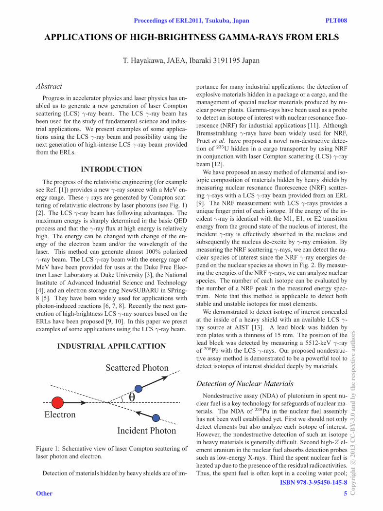
see Ref. [1]) provides a new γ-ray source with a MeV en-ergy range. These γ-rays are generated by Compton scat-tering of relativistic electrons by laser photons (see Fig. 1)[2]. The LCS γ-ray beam has following advantages. Themaximum energy is sharply determined in the basic QEDprocess and that the γ-ray flux at high energy is relativelyhigh. The energy can be changed with change of the en-ergy of the electron beam and/or the wavelength of thelaser. This method can generate almost 100% polarizedγ-ray beam. The LCS γ-ray beam with the energy rage ofMeV have been provided for uses at the Duke Free Elec-tron Laser Laboratory at Duke University [3], the NationalInstitute of Advanced Industrial Science and Technology[4], and an electron storage ring NewSUBARU in SPring-8 [5]. They have been widely used for applications withphoton-induced reactions [6, 7, 8]. Recently the next gen-eration of high-brightness LCS γ-ray sources based on theERLs have been proposed [9, 10]. In this paper we presetexamples of some applications using the LCS γ-ray beam.
INDUSTRIAL APPILCATTION
Incident Photon
Electron
Scattered Photon
Figure 1: Schemative view of laser Compton scattering oflaser photon and electron.
Detection of materials hidden by heavy shields are of im-
portance for many industrial applications: the detection ofexplosive materials hidden in a package or a cargo, and themanagement of special nuclear materials produced by nu-clear power plants. Gamma-rays have been used as a probeto detect an isotope of interest with nuclear resonance fluo-rescence (NRF) for industrial applications [11]. AlthoughBremsstrahlung γ-rays have been widely used for NRF,Pruet et al. have proposed a novel non-destructive detec-tion of 235U hidden in a cargo transporter by using NRFin conjunction with laser Compton scattering (LCS) γ-raybeam [12].We have proposed an assay method of elemental and iso-
topic composition of materials hidden by heavy shields bymeasuring nuclear resonance fluorescence (NRF) scatter-ing γ-rays with a LCS γ-ray beam provided from an ERL[9]. The NRF measurement with LCS γ-rays provides aunique finger print of each isotope. If the energy of the in-cident γ-ray is identical with the M1, E1, or E2 transitionenergy from the ground state of the nucleus of interest, theincident γ-ray is effectively absorbed in the nucleus andsubsequently the nucleus de-excite by γ-ray emission. Bymeasuring the NRF scattering γ-rays, we can detect the nu-clear species of interest since the NRF γ-ray energies de-pend on the nuclear species as shown in Fig. 2. By measur-ing the energies of the NRF γ-rays, we can analyze nuclearspecies. The number of each isotope can be evaluated bythe number of a NRF peak in the measured energy spec-trum. Note that this method is applicable to detect bothstable and unstable isotopes for most elements.We demonstrated to detect isotope of interest concealed
at the inside of a heavy shield with an available LCS γ-ray source at AIST [13]. A lead block was hidden byiron plates with a thinness of 15 mm. The position of thelead block was detected by measuring a 5512-keV γ-rayof 208Pb with the LCS γ-rays. Our proposed nondestruc-tive assay method is demonstrated to be a powerful tool todetect isotopes of interest shielded deeply by materials.
Nondestructive assay (NDA) of plutonium in spent nu-clear fuel is a key technology for safeguards of nuclear ma-terials. The NDA of 239Pu in the nuclear fuel assemblyhas not been well established yet. First we should not onlydetect elements but also analyze each isotope of interest.However, the nondestructive detection of such an isotopein heavy materials is generally difficult. Second high-Z el-ement uranium in the nuclear fuel absorbs detection probessuch as low-energy X-rays. Third the spent nuclear fuel isheated up due to the presence of the residual radioactivities.Thus, the spent fuel is often kept in a cooling water pool;
APPLICATIONS OF HIGH-BRIGHTNESS GAMMA-RAYS FROM ERLS
Detection of Nuclear Materials
Proceedings of ERL2011, Tsukuba, Japan PLT008
Other
ISBN 978-3-95450-145-8
5 Cop
yrig
htc ○
2013
CC
-BY-
3.0
and
byth
ere
spec
tive
auth
ors
ERL2011 SUMMARY OF WORKING GROUP 1: PROGRESS WITH DC PHOTOEMISSION ELECTRON SOURCES
B. Dunham, et al.
ERL2011 SUMMARY OF WORKING GROUP 1: PROGRESS WITH RF INJECTORS
T. Rao, et al.
ERL2011 SUMMARIES OF WORKING GROUP 1
WG1000 Proceedings of ERL2011, Tsukuba, Japan
ISBN 978-3-95450-145-8
10Cop
yrig
htc ○
2013
CC
-BY-
3.0
and
byth
ere
spec
tive
auth
ors
WG-1 Electron Sources

HIGH BRIGHTNESS THERMIONIC ELECTRON GUN PERFORMANCE
H. P. Bluem, D. Dowell*, A. M. M. Todd and L. M. Young*, Advanced Energy Systems (AES), Medford, NY, USA
Abstract Commercial Off-The-Shelf (COTS) gridded thermionic
cathode electron guns show promise for certain pulsed and CW electron beam applications. Accelerator systems utilizing these guns are presently being commissioned for pulse mode operation. Beam has been delivered to the IR wiggler of the Free Electron Laser (FEL) at the Fritz Haber Institute (FHI) der Max Planck Gesellschaft in Berlin [1] in advance of their October 28 Centennial. In the course of commissioning, we have performed emittance measurements that indicate the beam transverse rms emittance is 8-10mm-mrad at 20kV, consistent with our gun simulations. The nominal system operating voltage is 45kV. We have also studied the dependence of the extracted current as a function of RF power. After the initial low-level region, near linear behaviour is observed. The maximum value achieved was 806mA at 23.2kV and ~200W input RF, limited only by our available power supply. We find that pulsed beam applications must address the DC idle current that leaks from the cathode by utilizing grid or cathode pulsing. S-band systems are being commissioned at this time using both approaches. Lower frequency CW mode operation has also been proposed for high-power Energy Recovering Linacs (ERL) and FELs [2]. The above performance measurements indicate that adequate high-current thermionic gun beam quality is possible for IR FELs in such CW operation. The next step for this application, which is already in progress, is the design and testing of a gun with a normal-conducting pre-booster incorporating
solenoid focusing. This will raise the output energy to greater than 1 MeV so that the performance of the concept can be evaluated. The design must also consider ways to ameliorate beam scraping. Because the present COTS gun [3] is capable of delivering 5A, which greatly exceeds the requirements of all these applications, both CW and pulsed operation would benefit greatly from a redesigned gun with a smaller cathode and a reduced radius or totally eliminated cathode “hole”. It remains to be seen if totally eliminating the "hole" is possible while maintaining a robust gun HV and RF design in the presence of ion back bombardment.
INTRODUCTION
Standard thermionic guns for accelerator applications require complex, real-estate-consuming, bunching systems in order to produce high-quality electron beams and achieve low electron beam loss in the accelerating structures. Photocathode guns can be used to provide pre-modulated electron beams, but have not yet been shown to be practical for high-power CW systems, due principally to cathode lifetime issues at high current. In addition, they add their own, significant complexities to the system through the addition of the photocathode drive laser and the need for maintaining very good vacuum levels in the guns to avoid poisoning the cathodes. A gridded thermionic electron gun can provide a robust, economical, and compact solution to the provision of the high-performance, high-power electron beams required, when the grid is driven by an RF signal at the desired bunch
Figure 1: Layout of the FHI accelerator section from the gridded gun (left) to the second linac output (right).
____________________________________________
* Consultants to AES
WG1010 Proceedings of ERL2011, Tsukuba, Japan
ISBN 978-3-95450-145-8
30Cop
yrig
htc ○
2013
CC
-BY-
3.0
and
byth
ere
spec
tive
auth
ors
WG-1 Electron Sources
ERL2011 SUMMARY OF WORKING GROUP 2 BEAM DYNAMICS
C. Mayes, Cornell University, Ithaca, NY 14853, USA N. Nakamura, KEK Tsukuba, Ibaraki 305-0801, Japan
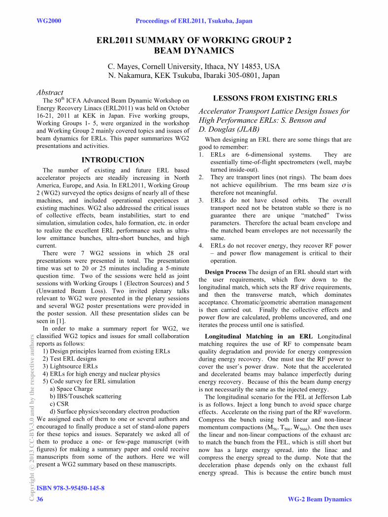
Abstract The 50th ICFA Advanced Beam Dynamic Workshop on
Energy Recovery Linacs (ERL2011) was held on October 16-21, 2011 at KEK in Japan. Five working groups, Working Groups 1- 5, were organized in the workshop and Working Group 2 mainly covered topics and issues of beam dynamics for ERLs. This paper summarizes WG2 presentations and activities.
INTRODUCTION
The number of existing and future ERL based accelerator projects are steadily increasing in North America, Europe, and Asia. In ERL2011, Working Group 2 (WG2) surveyed the optics designs of nearly all of these machines, and included operational experiences at existing machines. WG2 also addressed the critical issues of collective effects, beam instabilities, start to end simulation, simulation codes, halo formation, etc. in order to realize the excellent ERL performance such as ultra-low emittance bunches, ultra-short bunches, and high current.
There were 7 WG2 sessions in which 28 oral presentations were presented in total. The presentation time was set to 20 or 25 minutes including a 5-minute question time. Two of the sessions were held as joint sessions with Working Groups 1 (Electron Sources) and 5 (Unwanted Beam Loss). Two invited plenary talks relevant to WG2 were presented in the plenary sessions and several WG2 poster presentations were provided in the poster session. All these presentation slides can be seen in [1].
In order to make a summary report for WG2, we classified WG2 topics and issues for small collaboration reports as follows:
1) Design principles learned from existing ERLs 2) Test ERL designs 3) Lightsource ERLs 4) ERLs for high energy and nuclear physics 5) Code survey for ERL simulation
a) Space Charge b) IBS/Touschek scattering c) CSR d) Surface physics/secondary electron production
We assigned each of them to one or several authors and encouraged to finally produce a set of stand-alone papers for these topics and issues. Separately we asked all of them to produce a one- or few-page manuscript (with figures) for making a summary paper and could receive manuscripts from some of the authors. Here we will present a WG2 summary based on these manuscripts.
LESSONS FROM EXISTING ERLS
Accelerator Transport Lattice Design Issues for High Performance ERLs: S. Benson and D. Douglas (JLAB)
When designing an ERL there are some things that are good to remember: 1. ERLs are 6-dimensional systems. They are
essentially time-of-flight spectrometers (well, maybe turned inside-out).
2. They are transport lines (not rings). The beam does not achieve equilibrium. The rms beam size σ is therefore not meaningful.
3. ERLs do not have closed orbits. The overall transport need not be betatron stable so there is no guarantee there are unique “matched” Twiss parameters. Therefore the actual beam envelope and the matched beam envelopes are not necessarily the same.
4. ERLs do not recover energy, they recover RF power – and power flow management is critical to their operation.
Design Process The design of an ERL should start with the user requirements, which flow down to the longitudinal match, which sets the RF drive requirements, and then the transverse match, which dominates acceptance. Chromatic/geometric aberration management is then carried out. Finally the collective effects and power flow are calculated, problems uncovered, and one iterates the process until one is satisfied.
Longitudinal Matching in an ERL Longitudinal matching requires the use of RF to compensate beam quality degradation and provide for energy compression during energy recovery. One must use the RF power to cover the user’s power draw. Note that the accelerated and decelerated beams may balance imperfectly during energy recovery. Because of this the beam dump energy is not necessarily the same as the injected energy.
The longitudinal scenario for the FEL at Jefferson Lab is as follows. Inject a long bunch to avoid space charge effects. Accelerate on the rising part of the RF waveform. Compress the bunch using both linear and non-linear momentum compactions (M56, T566, W5666). One then uses the linear and non-linear compactions of the exhaust arc to match the bunch from the FEL, which is still short but now has a large energy spread, into the linac and compress the energy spread to the dump. Note that the deceleration phase depends only on the exhaust full energy spread. This is because the entire bunch must
WG2000 Proceedings of ERL2011, Tsukuba, Japan
ISBN 978-3-95450-145-8
36Cop
yrig
htc ○
2013
CC
-BY-
3.0
and
byth
ere
spec
tive
auth
ors
WG-2 Beam Dynamics

OPTICS LAYOUT FOR THE ERL TEST FACILITY AT PEKING UNIVERSITY*
S. L. Huang, K. X. Liu, S. W. Quan, L. Lin, F. Zhu, J. E. Chen,IHIP, School of Physics, Peking University, Beijing 100871, China
AbstractAn ERL test facility will be built at Peking University,
which incorporates the compact DC-SRF photo- injector, a superconducting module composed of two 9-cell TESLA-type cavities and a high average power IR FEL oscillator. Physical design of the test facility has been updated according to the expected characteristics of the DC-SRF photo-injector and accelerating module. In this work we will describe the physical issues in detail, especially the latest optics for the facility.
INTRODUCTIONAn ERL (Energy Recovery Linac) test facility is under
construction at Peking University, with the primary goals to study energy recovery, to demonstrate ERL-based FEL, and to develop the related technologies for ERL, especially those technologies on superconducting photo-injector and superconducting accelerator.
The test facility incorporates the compact DC-SRF photo-injector [1], a superconducting linac composed of two 9-cell TESLA-type cavities and a high average power IR FEL oscillator. The DC-SRF photo-injector, which integrates a DC pierce gun and a 3.5-cell superconducting RF cavity, was designed to produce 6 MeV electron beams with bunch charge of 60 pC, repetition rate of 26 MHz and normalized emittance less than 2 mm-mrad. At present, the DC-SRF photo-injector and 2K cryogenic system have been installed. Preliminary beam loading tests on the injector agree well with dynamics studies and indicate that it is expected to deliver electron beams with bunch charge of 60 pC, repetition rate of 26 MHz and normalized emittance better than 4 mm-mrad.
The single-pass superconducting linac will accelerate the electron beam to full energy of 30 MeV. After bunch compression to 4 ps (FWHM), the electron beam will be used to drive the IR FEL oscillator. The recirculated electron beam, after FEL interaction, is decelerated by the same linac 180 degrees out of the accelerating phase, which leads to energy recovery. Due to cost reason, the ERL test facility is designed to operate in long pulse mode, with a macro pulse length of 2 ms and repetition rate of 10 Hz.
The IR FEL oscillator is designed to lase within 5-10 um. Calculations show that out-coupled macro pulse power of hundreds watts can be achieved. FEL lasing within middle IR to THz regime is also under consideration, which may be realized by reducing the ERL full energy and using wigglers with longer period
length. A list of the baseline parameters for the ERL-based IR FEL is shown in Table 1.
Table 1: Baseline Parameters for the ERL-based FEL at Peking University
Electron Beam Parameters
Energy [MeV] 30
Energy spread, FWHM 0.32%
Bunch charge [pC] 60
Normalized emittance [mm-mrad] 4
Bunch length, FWHM [ps] 4
Micro pulse repetition rate [MHz] 26
Macro pulse length [ms] 2
Macro pulse repetition rate [Hz] 10
Wiggler Parameters
Period length [cm] 3
Gap [mm] 12 (21)
Kw, rms 1.14 (0.41)
Number of wiggler periods 40
Beta function @ wig centre, horiz. [m] 0.346
Beta function @ wig centre, vert. [m] 0.245 (0.677)
Alpha @ wiggler centre, horiz. 0
Alpha @ wiggler centre, vert. 0
Optical Cavity Parameters
Cavity length [m] 11.5305
Rayleigh range [m] 0.8
Mirror radius of curvature [m] 5.876
g1.g2 0.93
Extraneous loss 2%
Out-coupling 8% (1%)
FEL Parameters
Wavelength [um] 10.03 (5.1)
Gain 0.30 (0.10)
Out-coupled peak power [MW] 2.12 (0.97)
Out-coupled macro pulse avg power [W] 220.7 (101.2)
Out-coupled avg power [W] 4.4 (2.0)
Intra-cavity peak power [MW] 26.53 (97.31)
Intra-cavity avg power [W] 55.2 (202.4)____________________________________________
*Work supported by National Basic Research Program of China (2011CB808304).
Proceedings of ERL2011, Tsukuba, Japan WG2007
WG-2 Beam Dynamics
ISBN 978-3-95450-145-8
49 Cop
yrig
htc ○
2013
CC
-BY-
3.0
and
byth
ere
spec
tive
auth
ors
DESIGN STUDIES ON THE ERL TEST FACILITY AT IHEP-BEIJING
S.H.Wang, J.Q.Wang, S.Y. Chen, Y.L.Chi, G.W. Wang, J.S. Cao, S.G. Liu, J.Gao, J.Y. Zhai, W.B.Liu, X.H.Cui, J.Q. Xu, Z.S. Zhou, X.P. Li, H.H. Lu, Q. Xiao
Institute of High Energy Physics, CAS, Beijing 100049, China
Abstract A compact ERL test facility has been proposed at
IHEP-Beijing. The design study is briefly presented, including the main parameters, essential lattice and the features of the key components, such as photo-cathode DC gun and CW superconducting accelerating structures. Some important beam physics issues such as space charge effects, coherent synchrotron radiation (CSR) effect and beam break-up (BBU) effects are described with the simulation results.
INTRODUCTION The linac based Free Electron Laser (FEL), and the
Energy Recovery Linac (ERL) based light source are the two major types of the 4th generation light source. FEL has higher brightness, shorter pulse length and higher coherent features, but with a minor photon beam lines. ERL combines the good beam performance of the linac and good operation efficiency of the storage ring machine, although its brightness and coherent degree not as higher as FEL, but with many (more than 30) photon beam lines. Hence, both FEL and ERL cannot be replaced each other, we really need both of them. Based on this point, IHEP has proposed a suggestion of “one machine two purposes”, both FEL and ERL will share a same super-conducting (SC) linac for having a high efficiency [1]. The design study on the ERL-FEL Test Facility (ERL-TF) has been started at IHEP and being well progressed.
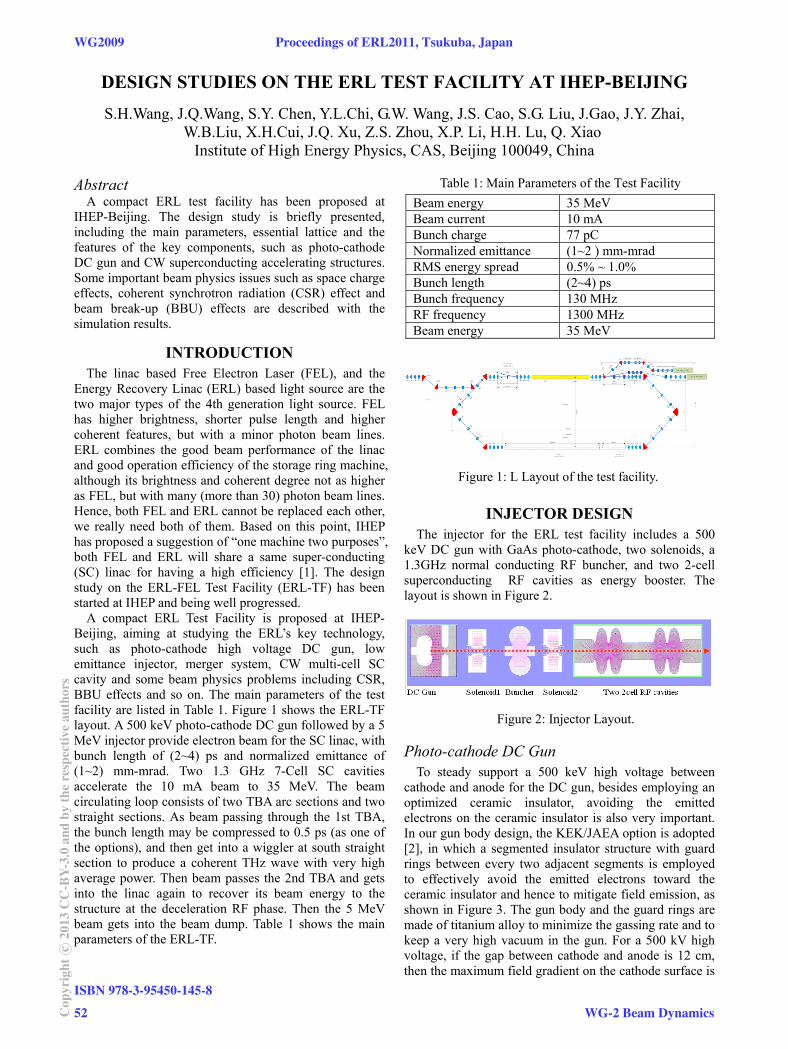
A compact ERL Test Facility is proposed at IHEP-Beijing, aiming at studying the ERL’s key technology, such as photo-cathode high voltage DC gun, low emittance injector, merger system, CW multi-cell SC cavity and some beam physics problems including CSR, BBU effects and so on. The main parameters of the test facility are listed in Table 1. Figure 1 shows the ERL-TF layout. A 500 keV photo-cathode DC gun followed by a 5 MeV injector provide electron beam for the SC linac, with bunch length of (2~4) ps and normalized emittance of (1~2) mm-mrad. Two 1.3 GHz 7-Cell SC cavities accelerate the 10 mA beam to 35 MeV. The beam circulating loop consists of two TBA arc sections and two straight sections. As beam passing through the 1st TBA, the bunch length may be compressed to 0.5 ps (as one of the options), and then get into a wiggler at south straight section to produce a coherent THz wave with very high average power. Then beam passes the 2nd TBA and gets into the linac again to recover its beam energy to the structure at the deceleration RF phase. Then the 5 MeV beam gets into the beam dump. Table 1 shows the main parameters of the ERL-TF.
Table 1: Main Parameters of the Test Facility
Beam energy 35 MeV Beam current 10 mA Bunch charge 77 pC Normalized emittance (1~2 ) mm-mrad RMS energy spread 0.5% ~ 1.0% Bunch length (2~4) ps Bunch frequency 130 MHz RF frequency 1300 MHz Beam energy 35 MeV
Figure 1: L Layout of the test facility.
INJECTOR DESIGN The injector for the ERL test facility includes a 500
keV DC gun with GaAs photo-cathode, two solenoids, a 1.3GHz normal conducting RF buncher, and two 2-cell superconducting RF cavities as energy booster. The layout is shown in Figure 2.
Figure 2: Injector Layout.
Photo-cathode DC Gun To steady support a 500 keV high voltage between
cathode and anode for the DC gun, besides employing an optimized ceramic insulator, avoiding the emitted electrons on the ceramic insulator is also very important. In our gun body design, the KEK/JAEA option is adopted [2], in which a segmented insulator structure with guard rings between every two adjacent segments is employed to effectively avoid the emitted electrons toward the ceramic insulator and hence to mitigate field emission, as shown in Figure 3. The gun body and the guard rings are made of titanium alloy to minimize the gassing rate and to keep a very high vacuum in the gun. For a 500 kV high voltage, if the gap between cathode and anode is 12 cm, then the maximum field gradient on the cathode surface is
WG2009 Proceedings of ERL2011, Tsukuba, Japan
ISBN 978-3-95450-145-8
52Cop
yrig
htc ○
2013
CC
-BY-
3.0
and
byth
ere
spec
tive
auth
ors
WG-2 Beam Dynamics
GENERATION OF HIGH-BRIGHTNESS GAMMA-RAYS FROM ENERGY-RECOVERY LINAC
R. Hajima, JAEA, Ibaraki 3191195 Japan
Abstract Energy-recovery linac (ERL) to generate an electron
beam of small emittance and high-average current is a suitable driver for laser Compton scattered -ray sources (LCS -ray). A combination of an ERL and a laser enhancement cavity will improve the performance of LCS -ray significantly in comparison with existing LCS sources based on linac and storage rings. Accelerator technologies relevant to ERL LCS sources, small-emittance gun and superconducting cavities, are same as ERL X-ray sources. We plan to demonstrate high-brightness LCS photon generation at the Compact ERL.
LASER COMPTON SCATTERED GAMMA-RAY SOURCES
The combination of an energy-recovery linac and a high-power mode-locked laser realizes significant improvement of -ray sources based on laser Compton scattering (LCS).
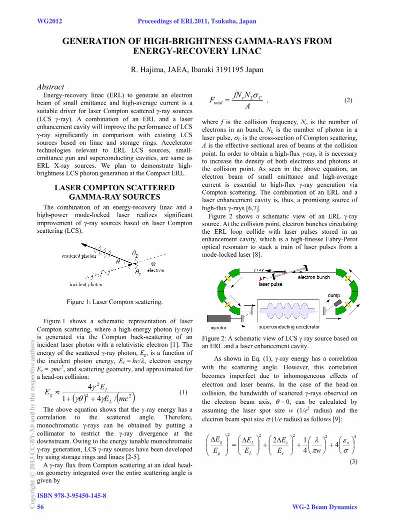
Figure 1: Laser Compton scattering.
Figure 1 shows a schematic representation of laser
Compton scattering, where a high-energy photon (-ray) is generated via the Compton back-scattering of an incident laser photon with a relativistic electron [1]. The energy of the scattered -ray photon, Eg, is a function of the incident photon energy, EL = hc/, electron energy Ee = mc2, and scattering geometry, and approximated for a head-on collision:
22
2
/41
4
mcEEE
L
Lg
(1)
The above equation shows that the -ray energy has a correlation to the scattered angle. Therefore, monochromatic -rays can be obtained by putting a collimator to restrict the -ray divergence at the downstream. Owing to the energy tunable monochromatic -ray generation, LCS -ray sources have been developed by using storage rings and linacs [2-5].
A -ray flux from Compton scattering at an ideal head-on geometry integrated over the entire scattering angle is given by
ANfNF CLe
total
, (2)
where f is the collision frequency, Ne is the number of electrons in an bunch, NL is the number of photon in a laser pulse, C is the cross-section of Compton scattering, A is the effective sectional area of beams at the collision point. In order to obtain a high-flux -ray, it is necessary to increase the density of both electrons and photons at the collision point. As seen in the above equation, an electron beam of small emittance and high-average current is essential to high-flux -ray generation via Compton scattering. The combination of an ERL and a laser enhancement cavity is, thus, a promising source of high-flux -rays [6,7].
Figure 2 shows a schematic view of an ERL -ray source. At the collision point, electron bunches circulating the ERL loop collide with laser pulses stored in an enhancement cavity, which is a high-finesse Fabry-Perot optical resonator to stack a train of laser pulses from a mode-locked laser [8].
Figure 2: A schematic view of LCS -ray source based on an ERL and a laser enhancement cavity.
As shown in Eq. (1), -ray energy has a correlation with the scattering angle. However, this correlation becomes imperfect due to inhomogeneous effects of electron and laser beams. In the case of the head-on collision, the bandwidth of scattered -rays observed on the electron beam axis, = 0, can be calculated by assuming the laser spot size w (1/e2 radius) and the electron beam spot size (1/e radius) as follows [9]:
42222
44
12
n
e
e
L
L
g
g
wEE
EE
EE
(3)
WG2012 Proceedings of ERL2011, Tsukuba, Japan
ISBN 978-3-95450-145-8
56Cop
yrig
htc ○
2013
CC
-BY-
3.0
and
byth
ere
spec
tive
auth
ors
WG-2 Beam Dynamics
MULTITURN ERL X-RAY SOURCE (MARS) FEASIBILITY STUDY G.N. Kulipanov, Ya.V. Getmanov, O.A. Shevchenko, A.N. Skrinsky, A.G. Tribendis, V.N. Volkov,
Budker INP, Novosibirsk, Russia N.A. Vinokurov
Budker INP, Novosibirsk, Russia and Korea Atomic Energy Research Institute, Daejeon, Korea
Abstract Multiturn energy recovery linacs (ERL) looks very
promising for making ERLs less expensive and more flexible, but have serious intrinsic problems. At this time only one multiturn ERL exists. This Novosibirsk ERL operates with two orbits and two free electron lasers now. The conception of Multiturn Accelerator-recuperator Radiation Source (MARS) was proposed in 1997 by G.N. Kulipanov, A.N. Skrinsky and N.A. Vinokurov. The use of the two-linac ERL (D. Douglas, 2001) makes multiturn operation much easier. The feasibility study for such ERL-based high brightness x-ray source is presented.
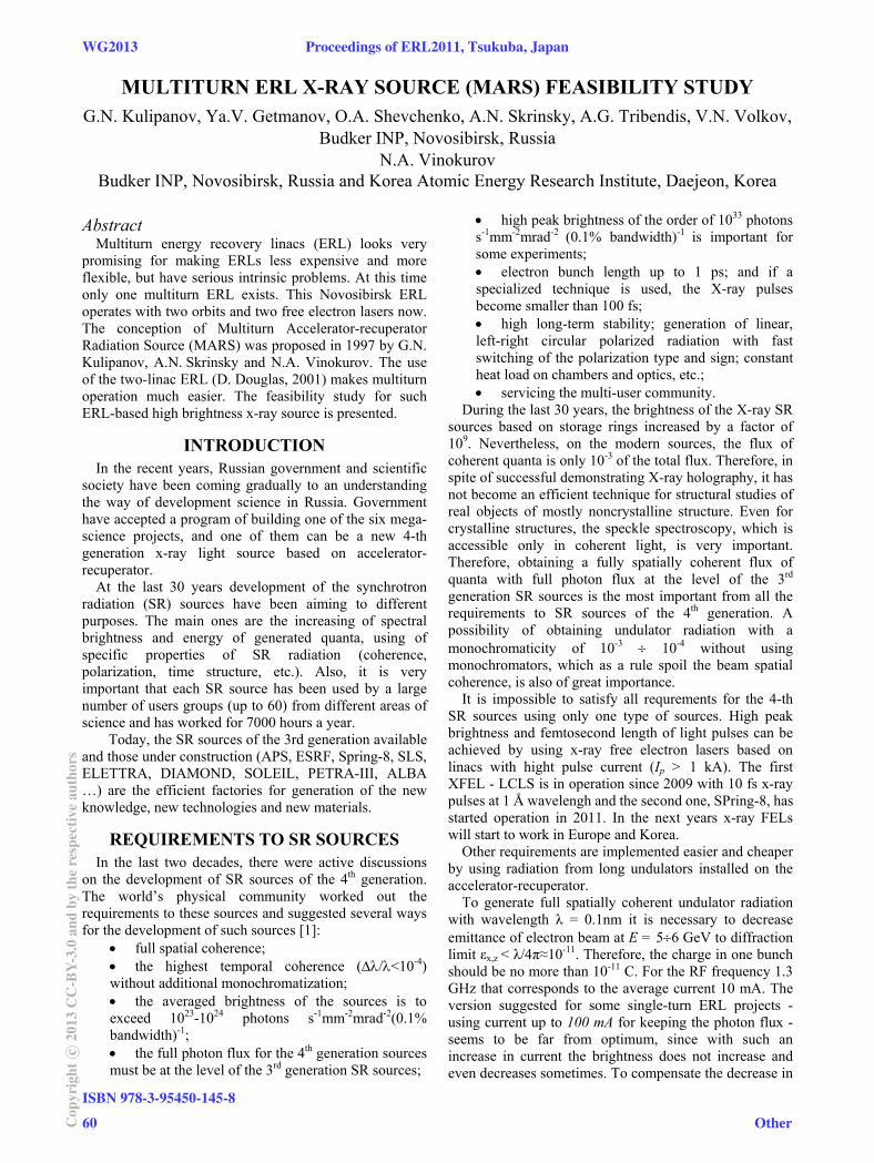
INTRODUCTION In the recent years, Russian government and scientific
society have been coming gradually to an understanding the way of development science in Russia. Government have accepted a program of building one of the six mega-science projects, and one of them can be a new 4-th generation x-ray light source based on accelerator-recuperator.
At the last 30 years development of the synchrotron radiation (SR) sources have been aiming to different purposes. The main ones are the increasing of spectral brightness and energy of generated quanta, using of specific properties of SR radiation (coherence, polarization, time structure, etc.). Also, it is very important that each SR source has been used by a large number of users groups (up to 60) from different areas of science and has worked for 7000 hours a year.
Today, the SR sources of the 3rd generation available and those under construction (APS, ESRF, Spring-8, SLS, ELETTRA, DIAMOND, SOLEIL, PETRA-III, ALBA …) are the efficient factories for generation of the new knowledge, new technologies and new materials.
REQUIREMENTS TO SR SOURCES In the last two decades, there were active discussions
on the development of SR sources of the 4th generation. The world’s physical community worked out the requirements to these sources and suggested several ways for the development of such sources [1]:
full spatial coherence; the highest temporal coherence (/<10-4) without additional monochromatization; the averaged brightness of the sources is to exceed 1023-1024 photons s-1mm-2mrad-2(0.1% bandwidth)-1; the full photon flux for the 4th generation sources must be at the level of the 3rd generation SR sources;
high peak brightness of the order of 1033 photons s-1mm-2mrad-2 (0.1% bandwidth)-1 is important for some experiments; electron bunch length up to 1 ps; and if a specialized technique is used, the X-ray pulses become smaller than 100 fs; high long-term stability; generation of linear, left-right circular polarized radiation with fast switching of the polarization type and sign; constant heat load on chambers and optics, etc.; servicing the multi-user community.
During the last 30 years, the brightness of the X-ray SR sources based on storage rings increased by a factor of 109. Nevertheless, on the modern sources, the flux of coherent quanta is only 10-3 of the total flux. Therefore, in spite of successful demonstrating X-ray holography, it has not become an efficient technique for structural studies of real objects of mostly noncrystalline structure. Even for crystalline structures, the speckle spectroscopy, which is accessible only in coherent light, is very important. Therefore, obtaining a fully spatially coherent flux of quanta with full photon flux at the level of the 3rd generation SR sources is the most important from all the requirements to SR sources of the 4th generation. A possibility of obtaining undulator radiation with a monochromaticity of 10-3 10-4 without using monochromators, which as a rule spoil the beam spatial coherence, is also of great importance.
It is impossible to satisfy all requrements for the 4-th SR sources using only one type of sources. High peak brightness and femtosecond length of light pulses can be achieved by using x-ray free electron lasers based on linacs with hight pulse current (Ip > 1 kA). The first XFEL - LCLS is in operation since 2009 with 10 fs x-ray pulses at 1 Å wavelengh and the second one, SPring-8, has started operation in 2011. In the next years x-ray FELs will start to work in Europe and Korea.
Other requirements are implemented easier and cheaper by using radiation from long undulators installed on the accelerator-recuperator.
To generate full spatially coherent undulator radiation with wavelength λ = 0.1nm it is necessary to decrease emittance of electron beam at E = 56 GeV to diffraction limit εx,z < λ/4π≈10-11. Therefore, the charge in one bunch should be no more than 10-11 C. For the RF frequency 1.3 GHz that corresponds to the average current 10 mA. The version suggested for some single-turn ERL projects - using current up to 100 mA for keeping the photon flux - seems to be far from optimum, since with such an increase in current the brightness does not increase and even decreases sometimes. To compensate the decrease in
WG2013 Proceedings of ERL2011, Tsukuba, Japan
ISBN 978-3-95450-145-8
60Cop
yrig
htc ○
2013
CC
-BY-
3.0
and
byth
ere
spec
tive
auth
ors
Other
WAKE FIELDS AND ENERGY SPREAD FOR THE eRHIC ERL*
A.V. Fedotov# and D. Kayran, BNL, Upton, NY 11973, USA
Abstract Wake fields in high-current ERLs can cause significant
beam quality degradations. Here we summarize effects of coherent synchrotron radiation, resistive wall, accelerating cavities and wall roughness for ERL parameters of the eRHIC project. A possibility of compensation of such correlated energy spread is also presented. An emphasis in the discussion is made on the suppression of coherent synchrotron radiation due to shielding and a possible reduction of wall roughness effects for realistic surfaces.
INTRODUCTION
In this report we discuss the wake fields with a focus on their effect on the energy spread of the beam. Other effects of wake fields are addressed elsewhere. An energy spread builds up during a pass though a very long beam transport in the eRHIC ERL under design [1]. Such energy spread become important when beam is decelerated to low energy, and needs to be corrected.
Several effects, such as Coherent Synchrotron Radiation (CSR), Resistive Wall (RW), accelerating RF cavities (RF) and Wall Roughness (WR) were considered. In this paper, we briefly summarize major contributions to energy spread from the wake fields for eRHIC parameters, and present possible energy spread compensation for decelerated beam. In the rest of the report we discuss effects which we believe are suppressed for the eRHIC parameters.
SOURCES OF ENERGY SPREAD FOR eRHIC ERL
For the eRHIC project, electron beam with high peak current has to go through the present tunnel of the Relativistic Heavy Ion Collider (RHIC) 6 times to reach the top energy (at which electron beam will collide with the ion beam) and then additional 6 times to be decelerated before going to the dump. To save on the cost of the vacuum chambers and magnets very small aperture of vacuum chambers are considered. As a result, such effects as RW and WR are strongly enhanced.
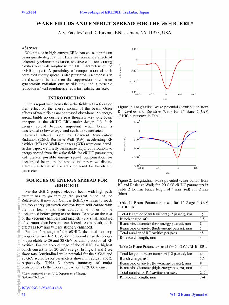
For the first stage of the eRHIC, the maximum top energy is presently 5 GeV, for the second stage the energy is upgradable to 20 and 30 GeV by adding additional RF cavities. For the second stage of the eRHIC, the highest bunch current is for 20 GeV energy. In Figs. 1 and 2 we show total longitudinal wake potential for the 5 GeV and 20 GeV scenarios for parameters shown in Tables 1 and 2, respectively. Table 3 shows summary of major contributions to the energy spread for the 20 GeV case.
0.02 0.01 0 0.01 0.021.5 107
1 107
5 106
0
5 106
z [m]
wak
e po
tent
ial [
V]
Figure 1: Longitudinal wake potential (contribution from RF cavities and Resistive Wall) for 1st stage 5 GeV eRHIC parameters in Table 1.
0.02 0.01 0 0.018 107
6 107
4 107
2 107
0
2 107
z [m]
wak
e po
tent
ial [
V]
Figure 2: Longitudinal wake potential (contribution from RF and Resistive Wall) for 20 GeV eRHIC parameters in Table 2 for rms bunch length of 4 mm (red) and 2 mm (blue). Table 1: Beam Parameters used for 1st Stage 5 GeV eRHIC ERL
Total length of beam transport (12 passes), km Bunch charge, nC 3.5Beam pipe diameter (low-energy passes), mm 8 Beam pipe diameter (high-energy passes), mm 5 Total number of RF cavities per pass 48 Rms bunch length, mm 4
Table 2: Beam Parameters used for 20 GeV eRHIC ERL
Total length of beam transport (12 passes), km Bunch charge, nC 3.5Beam pipe diameter (low-energy passes), mm 8 Beam pipe diameter (high-energy passes), mm 5 Total number of RF cavities per pass 240Rms bunch length, mm 2-4
___________________________________________
*Work supported by the U.S. Department of Energy #[email protected]
WG2014 Proceedings of ERL2011, Tsukuba, Japan
ISBN 978-3-95450-145-8
64Cop
yrig
htc ○
2013
CC
-BY-
3.0
and
byth
ere
spec
tive
auth
ors
WG-2 Beam Dynamics
CALCULATION OF CSR IMPEDANCE USING MESH METHOD
D. Zhou∗, KEK, 1-1 Oho, Tsukuba, Ibaraki 305-0801, Japan
AbstractA new code CSRZ was developed to investigate the lon-
gitudinal coherent synchrotron radiation (CSR) impedancefor a single or a series of bending magnets. To calculateCSR impedance, the mesh method developed by T. Agohand K. Yokoya [1] was adapted to the case of a curved rect-angular chamber with variable bending radius. The methodis based on the integration of the parabolic equation in thefrequency domain in a curvilinear coordinate system. In thecode CSRZ, the curvature of the beam trajectory can be setto be an arbitrary function of the distance along the beamorbit. Thus it allows calculating CSR impedance generatedby either a single bending magnet or a series of bendingmagnets. In this paper, we first describe the code and for-malism for CSR calculation. Then we apply the code tocalculate the longitudinal CSR impedance using an exam-ple appearing in the compact energy recovery linac (cERL)project at KEK.
INTRODUCTION
The mesh method was devised by Agoh and Yokoya andhas been used to calculate the longitudinal CSR impedancein a single bending magnet [1]. The most important ideawas based on paraxial approximation of Maxwell’s equa-tions. A simplified set of parabolic equations was found todescribe the evolutions of CSR fields, i.e.
∂ �E⊥∂s
=i
2k
[∇2
⊥ �E⊥ − 1ε0∇⊥ρ0
+ 2k2
(x
R(s)− 1
2γ2
)�E⊥
], (1)
where �E⊥ is the transverse electric field, and R(s) is thebending radius at distance s along the beam orbit. ε0 is thevacuum permittivity. γ is the Lorentz factor, representingthe beam energy. The term of 1/γ 2 indicates the normalspace-charge effect. The beam is assumed to be rigid, i.e.the beam charge density ρ0 does not vary along s. Equation(1) also describes the field evolution in a straight chamberwhere the inverse bending radius is zero. With paraxial ap-proximation, the longitudinal electric field is approximatedby
Es =i
k
(∇⊥ · �E⊥ − μ0cJs
), (2)
where μ0 is the vacuum permeability, c is the speed of lightin vacuum, and Js = ρ0c is the current density.
The spatially discretized version of Eq. (1) was solvedby an iterative procedure on a uniform grid. It was pointedout in Ref. [1] that this mesh method is very flexible andcan be extended in a number of ways.The original motivation of developing an independent
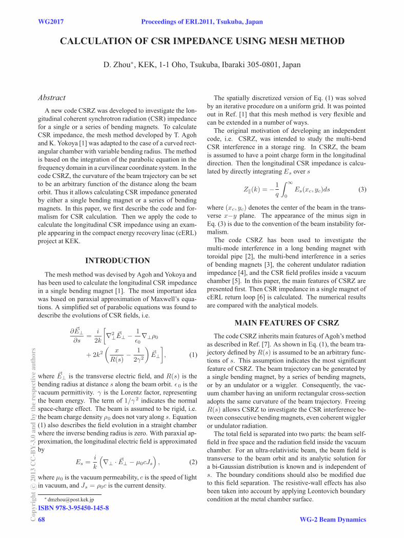
code, i.e. CSRZ, was intended to study the multi-bendCSR interference in a storage ring. In CSRZ, the beamis assumed to have a point charge form in the longitudinaldirection. Then the longitudinal CSR impedance is calcu-lated by directly integratingEs over s
Z‖(k) = −1q
∫ ∞
0
Es(xc, yc)ds (3)
where (xc, yc) denotes the center of the beam in the trans-verse x−y plane. The appearance of the minus sign inEq. (3) is due to the convention of the beam instability for-malism.The code CSRZ has been used to investigate the
multi-mode interference in a long bending magnet withtoroidal pipe [2], the multi-bend interference in a seriesof bending magnets [3], the coherent undulator radiationimpedance [4], and the CSR field profiles inside a vacuumchamber [5]. In this paper, the main features of CSRZ arepresented first. Then CSR impedance in a single magnet ofcERL return loop [6] is calculated. The numerical resultsare compared with the analytical models.
MAIN FEATURES OF CSRZThe code CSRZ inherits main features of Agoh’s method
as described in Ref. [7]. As shown in Eq. (1), the beam tra-jectory defined by R(s) is assumed to be an arbitrary func-tions of s. This assumption indicates the most significantfeature of CSRZ. The beam trajectory can be generated bya single bending magnet, by a series of bending magnets,or by an undulator or a wiggler. Consequently, the vac-uum chamber having an uniform rectangular cross-sectionadopts the same curvature of the beam trajectory. FreeingR(s) allows CSRZ to investigate the CSR interference be-tween consecutive bendingmagnets, even coherent wiggleror undulator radiation.The total field is separated into two parts: the beam self-
field in free space and the radiation field inside the vacuumchamber. For an ultra-relativistic beam, the beam field istransverse to the beam orbit and its analytic solution fora bi-Gaussian distribution is known and is independent ofs. The boundary conditions should also be modified dueto this field separation. The resistive-wall effects has alsobeen taken into account by applying Leontovich boundarycondition at the metal chamber surface.
WG2017 Proceedings of ERL2011, Tsukuba, Japan
ISBN 978-3-95450-145-8
68Cop
yrig
htc ○
2013
CC
-BY-
3.0
and
byth
ere
spec
tive
auth
ors
WG-2 Beam Dynamics
INTRA-BEAM SCATTERING AND ITS APPLICATION TO ERL*
A.V. Fedotov#, BNL, Upton, NY 11973, USA
Abstract Treatment of Coulomb collisions within the beam requires consideration of both large and small angle scattering. Such collisions lead to the Touschek effect and Intrabeam Scattering (IBS). The Touschek effect refers to particle loss as a result of a single collision, where only transfer from the transverse direction into longitudinal plays a role. It is important to consider this effect for ERL design to have an appropriate choice of collimation system. The IBS is a diffusion process which leads to changes of beam distribution but does not necessarily result in a beam loss. Evaluation of IBS in ERLs, where beam distribution is non-Gaussian, requires special treatment. Here we describe the IBS and Touschek effects with application to ERLs.
INTRODUCTION
A subject of Coulomb scattering within charged particle beams is well established in circular particle accelerators. In this report a brief summary is given with an emphasis on applications to the future high-current high-brightness Energy Recovery Linacs (ERLs). Here we do not attempt to produce a comprehensive list of references on existing IBS models but rather limit discussion to just a few with which we had some experience. Some specifics of the Touschek effect and IBS in ERLs are also discussed.
The effect when particles within the beam can be lost as a result of a single collision event (large-angle scattering) is called Touschek effect [1]. The cause of the Touschek effect is the transformation of the transverse momentum in longitudinal with its amplification by the relativistic factor The particles are lost after collision if the change introduced in the longitudinal momentum is larger than the energy acceptance of accelerator.
When the scattering angles are small, random addition of such small scattering events can lead to a growth of beam dimensions. Such a multiple Coulomb scattering was first applied to explain emittance growth in electron beams [2, 3] and was called "multiple Touschek effect". The multiple Coulomb scattering was later generalized by Piwinski for proton machines without making any restrictions on the magnitude of beam temperatures, thus making it possible to transfer energy from the longitudinal into transverse via collisions [4]. This generalized treatment of multiple small-angle Coulomb scattering was also renamed as the Intrabeam Scattering (IBS) [4]. The IBS theory was later extended to include variations of the betatron functions and momentum dispersion function along the lattice of accelerator, and was summarized in reports by Martini [5] and Piwinski [6].
The different approach to IBS using the scattering matrix formalism from quantum electrodynamics was used by Bjorken and Mtingwa (B-M model) [7]. Both B-M and Martini's models are in good agreement with one another.
Note that a variety of IBS models were derived based on the original models of Bjorken-Mtingwa, Martini and Piwinski, which can produce different results, especially when used outside their region of applicability. In our experience with IBS simulations and experimental verification, exact Bjorken-Mtingwa [7] and Martini [5] models produced similar results both above and below transition energy of an accelerator.
Typical limitation of analytic models of IBS is that they are developed in an assumption of Gaussian distribution. In most situations such treatment is justified and models provide good agreement with experimental measurements (see Ref. [8], for example). However, when distribution starts to deviate from Gaussian significantly, assumption of Gaussian distribution may result in inaccurate predictions. To address this issue 1-D Fokker-Planck approach was effectively used before [9]-[10].
A more dramatic situation occurs when there is an externally applied force, like electron cooling. Since electron cooling force depends on the amplitudes of individual particles, the distribution under such force very quickly deviates from Gaussian. The problem of how to accurately account for IBS for such distributions became of special interest with a proposal to use electron cooling directly in a collider. Several approximate models were developed in the past to address this issue [11-13].
A more general description requires full treatment of kinetic problem. Such a treatment was introduced in the BETACOOL code [14] under the name “local IBS model” [15]. In addition to extensive numerical tests it was also benchmarked vs. experimental data with results reported in Ref. [16].
With application to ERLs, an approximate treatment using sliced-beam approach was suggested in Ref. [17]. In present report, a comparison between sliced-beam and local-IBS models is presented.
An analytic analysis of Coulomb scattering for a variety of distributions in 3-D was also performed in the past to understand possible halo formation in linear accelerators [18, 19]. These studies also discussed an extent of beam halo due to such collisions.
___________________________________________
*Work supported by the U.S. Department of Energy #[email protected]
Proceedings of ERL2011, Tsukuba, Japan WG2019
WG-2 Beam Dynamics
ISBN 978-3-95450-145-8
73 Cop
yrig
htc ○
2013
CC
-BY-
3.0
and
byth
ere
spec
tive
auth
ors

INvESTIGATION OF THE EFFECT OF SPACE CHARGE IN THE
Ji-Gwang Hwang and Eun-San Kim∗,Kyungpook National University. 1370 Sankyok-dong, Buk-ku, Daegu, 702-701, Korea
Tsukasa Miyajima,KEK, Tsukuba, Ibaraki 305-0801, Japan
AbstractCompact energy recover linear(ERL) accelerator is a
prototype of the 5 GeV ERL accelerator at KEK. The injec-tor system has two SRF cavities which have the frequencyof 1.3 GHz. It accelerates the bunches to the energy of 5MeV. This beam was injected to the main ring and then itwas accelerated to energy of 35 MeV at the main super-conducting RF linac. Due to the low beam energy on themain ring, the investigation of the effect of space charge(SC) which causes the growth of the energy spread is im-portant to produce the low emittance beam. For the pro-duction of the low emittance beam, the optimization of themerger was performed. To obtain smaller emittance at theexit of merger, the effect of the energy spread was also in-vestigated by changing of the kd which is defined by theratio of energy spread to length of the bunch. In this calcu-lation, we got the noralized transverse emittance of 0.735mm·mrad at the exit of merger section.
INTRODUCTIONThe Energy Recovery Linear accelerator (ERL) is one of
the candidates for the fourth generation light sources thatcan meet these requirements. The main feature of the ERLis production of low-emittance( pm) beam with energy re-covery in the main linac. The ERL requires sophisticatedtechnology of superconducting accelerator. The generationof ultra-low emittance beams is need to demonstrate beforeconstructing Multi-GeV ERL. The compact-ERL at KEK,in the final stage, will provide a beam energy of around 125MeV and a bunch charge of 77 pC, which is a prototype forthe future 5 GeV ERL at KEK. The layout of the compact-ERL is shown in Fig 1. The c-ERL consists of an injec-tor system, a merger section, a superconducting RF (SRF)section, two return loops and two straight sections[3]. Inthe early comissioning phase of the compact-ERL, the en-ergy is 35 MeV with a bunch charge of 7.7 pC. The elec-tron injector system consists of a 500 kV photo cathode DCgun, two solenoid magnets, a buncher cavity, three super-conducting RF cavities, seven quadrupole magnets and amerger section. In the second comissioning phase, the in-jector produces electron beams with a bunch charge of 77pC, beam energy of 5 MeV and bunch length of 0.6 mmrms. The beam energy is increased by 30 MeV with two9 cell SRF cavities. Since the beam energy in c-ERL is a
low with high charge, we need to consider the several ef-fects, e.g., the space charge effect, the coherent synchrotronradiation (CSR) effect, the wake function, ion effects andbeam break up[4]. In the case of low energy, the elec-tric force which caused the growth of the energy spread ismore stronger than the magnetic force. It called SC effect.The emittance growth due to the space charge (SC) effectis dominated for the case of low-energy, around 5 MeV [5],and causes growth of the energy spread. The energy spreadinduced in an achromatic cell results in the growth of pro-jection emittance at the exit of the achromatic cell. It isknown that this emittance growth can be compensated bysetting the cell-to-cell betatron phase advance at an appro-priate value[6].
Figure 1: Layout of a compact-ERL.
ENERGY SPREAD GROWTH DUE TOTHE SC EFFECT
The low energy beam injected from the injector systemmerges with the circulating high energy beams. For thebeam mergence, after passing the merger section, the ra-tio of circulating energy to injected energy should be largebecause the circulating beam is also kicked and needs tobe bumped at the merger section. A merger section with3-dipole was adopted for the flexible beam transport of thehigh energy circulating beam. The layout of the 3-dipolesmerger is shown in Fig. 2.
Figure 2: Layout of a merger section.
COMPACT-ENERGY RECOvERY LINAC
WG2025 Proceedings of ERL2011, Tsukuba, Japan
ISBN 978-3-95450-145-8
78Cop
yrig
htc ○
2013
CC
-BY-
3.0
and
byth
ere
spec
tive
auth
ors
WG-2 Beam Dynamics
FABRICATION OF SUPERCONDUCTING RF CAVITY AT MHI
Haruki Hitomi, Fumiaki Inoue, Hiroshi Hara, Katsuya Sennyu, Kohei Kanaoka, Takeshi Yanagisawa
Mitsubishi Heavy Industries, Ltd, Kobe, Hyogo, 652-8585, Japan
Abstract We have supplied some 1.3 GHz superconducting RF
cavities for STF project and cERL project for few years. Recently, we have manufactured STF phase 2.0 cavities (MHI-#12 to #22). Some of them achieved ILC specification in vertical test at KEK. We have also manufactured three sets of 2-cell cavities for injector linac modules of cERL and two sets of 9-cell cavities for main linac modules of cERL. These cavities were governed to high pressure gas safety law in Japan. We report recent activities of superconducting RF cavity at MHI in this paper.
INTRODUCTION MHI has supplied 1.3 GHz superconducting RF cavity
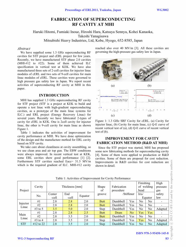
for STF project (STF is a project at KEK to build and operate a test linac with high-gradient superconducting cavities, as a prototype of the main linac systems for ILC.) and ERL project (Energy Recovery Linac) for several years. Recently we have fabricated 2-types of cavity for cERL in KEK. One is 2cell cavity for injector linac, the other is 9-cell cavity for main linac as shown Figure 1.
Table 1 indicates the activities of improvement for cavity performance at MHI. We have done optimization of the design and the manufacture method for ERL cavity based on STF cavity.
We take care about cleanliness at cavity assembling, so we use clean area and air top gun. The EBW conditions were always improved. In recent vertical test at KEK, some ERL cavities show good performance [1] [2]. Furthermore STF cavities reached Eacc= 31.5 MV/m which is the required gradient of ILC. MHI-#12 cavity
reached also over 40 MV/m [3]. All these cavities are governing the high-pressure gas safety law in Japan.
(a) (b)
(c) (d)
Figure 1: 1.3 GHz SRF Cavity for cERL. (a) Cavity for injector linac, (b) Cavity for main linac, (c) Q-E curve of recent vertical test of (a), (d) Q-E curve of recent vertical test of (b).
IMPROVEMENT FOR CAVITY FABRICATION METHOD (R&D AT MHI)
Since the STF project was started, MHI has proposed some new fabricating methods for superconducting cavity [4]. Some of them were applied to production or R&D cavities. Some of them are proposal for cost reduction. Improvements in R&D cavities for cost reduction are shown in detail.
Table 1: Activities of Improvement for Cavity Performance
Project Cavity Thickness [mm] Shape
of groove
Fabrication procedure
/Stiffener
Finishing of welding bead
High pressure gas safety law No.
Center -cell
End -cell
Equator Iris/
Equator
Injector Linac
#1 2.8 2.8 2.0 Butt Dumbbell Yes No No - #2 2.8 2.8 2.0 Butt Dumbbell Yes No No -
#3 to 5 3.5 5.0 2.0 Step Dumbbell Yes No No Adapted
Main Linac
#1 2.8 2.8 2.5 Butt Dram No Yes Yes - #2 2.8 3.5 2.0 Butt Dumbbell Yes No No -
#3 to 4 2.8 3.5 2.0 Step Dumbbell Yes Yes No AdaptedSTF #12 to 22 2.8 3.5 2.0 Step Dumbbell Yes No No Adapted
Proceedings of ERL2011, Tsukuba, Japan WG3002
WG-3 Superconducting RF
ISBN 978-3-95450-145-8
83 Cop
yrig
htc ○
2013
CC
-BY-
3.0
and
byth
ere
spec
tive
auth
ors
HOM PROPERTIES OF MAIN LINAC FOR IN JAPAN
M. Sawamura#, JAEA, Tokai, Ibaraki 319-1195, Japan T. Furuya, H. Sakai, K. Umemori, KEK, Tsukuba, Ibaraki 305-0801, Japan
K. Shinoe, ISSP, University of Tokyo, Kashiwa, Chiba 277-8581, Japan E. Cenni, The Graduate University for Advanced Studies, Tsukuba, Ibaraki 305-0801, Japan
Abstract
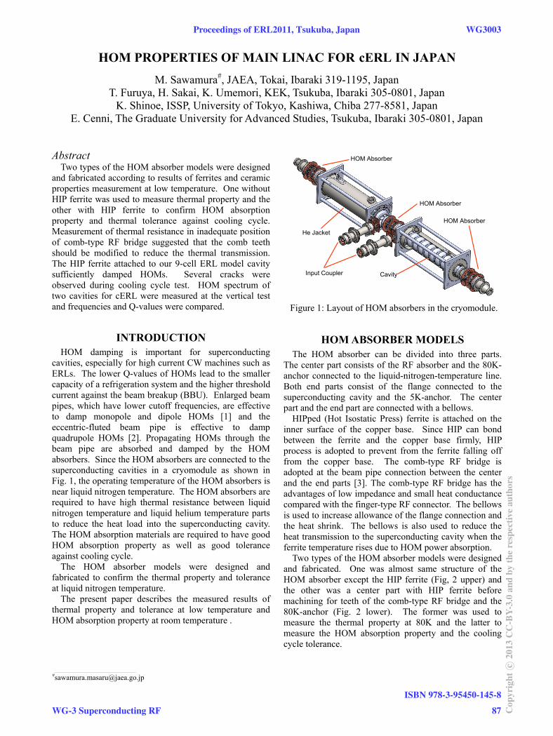
Two types of the HOM absorber models were designed and fabricated according to results of ferrites and ceramic properties measurement at low temperature. One without HIP ferrite was used to measure thermal property and the other with HIP ferrite to confirm HOM absorption property and thermal tolerance against cooling cycle. Measurement of thermal resistance in inadequate position of comb-type RF bridge suggested that the comb teeth should be modified to reduce the thermal transmission. The HIP ferrite attached to our 9-cell ERL model cavity sufficiently damped HOMs. Several cracks were observed during cooling cycle test. HOM spectrum of two cavities for cERL were measured at the vertical test and frequencies and Q-values were compared.
INTRODUCTION HOM damping is important for superconducting
cavities, especially for high current CW machines such as ERLs. The lower Q-values of HOMs lead to the smaller capacity of a refrigeration system and the higher threshold current against the beam breakup (BBU). Enlarged beam pipes, which have lower cutoff frequencies, are effective to damp monopole and dipole HOMs [1] and the eccentric-fluted beam pipe is effective to damp quadrupole HOMs [2]. Propagating HOMs through the beam pipe are absorbed and damped by the HOM absorbers. Since the HOM absorbers are connected to the superconducting cavities in a cryomodule as shown in Fig. 1, the operating temperature of the HOM absorbers is near liquid nitrogen temperature. The HOM absorbers are required to have high thermal resistance between liquid nitrogen temperature and liquid helium temperature parts to reduce the heat load into the superconducting cavity. The HOM absorption materials are required to have good HOM absorption property as well as good tolerance against cooling cycle.
The HOM absorber models were designed and fabricated to confirm the thermal property and tolerance at liquid nitrogen temperature.
The present paper describes the measured results of thermal property and tolerance at low temperature and HOM absorption property at room temperature .
HOM ABSORBER MODELS The HOM absorber can be divided into three parts.
The center part consists of the RF absorber and the 80K-anchor connected to the liquid-nitrogen-temperature line. Both end parts consist of the flange connected to the superconducting cavity and the 5K-anchor. The center part and the end part are connected with a bellows.
HIPped (Hot Isostatic Press) ferrite is attached on the inner surface of the copper base. Since HIP can bond between the ferrite and the copper base firmly, HIP process is adopted to prevent from the ferrite falling off from the copper base. The comb-type RF bridge is adopted at the beam pipe connection between the center and the end parts [3]. The comb-type RF bridge has the advantages of low impedance and small heat conductance compared with the finger-type RF connector. The bellows is used to increase allowance of the flange connection and the heat shrink. The bellows is also used to reduce the heat transmission to the superconducting cavity when the ferrite temperature rises due to HOM power absorption.
Two types of the HOM absorber models were designed and fabricated. One was almost same structure of the HOM absorber except the HIP ferrite (Fig, 2 upper) and the other was a center part with HIP ferrite before machining for teeth of the comb-type RF bridge and the 80K-anchor (Fig. 2 lower). The former was used to measure the thermal property at 80K and the latter to measure the HOM absorption property and the cooling cycle tolerance.
HOM Absorber
Input Coupler
He Jacket
Cavity
HOM Absorber
HOM Absorber
HOM Absorber
Input Coupler
He Jacket
Cavity
HOM Absorber
HOM Absorber
Figure 1: Layout of HOM absorbers in the cryomodule.
___________________________________________ #[email protected]
cERL
Proceedings of ERL2011, Tsukuba, Japan WG3003
WG-3 Superconducting RF
ISBN 978-3-95450-145-8
87 Cop
yrig
htc ○
2013
CC
-BY-
3.0
and
byth
ere
spec
tive
auth
ors
DEVELOPMENT OF INPUT COUPLER FOR COMPACT ERL MAIN LINAC
Hiroshi Sakai#, Takaaki Furuya, Masato Sato, Kenji Shinoe, Kensei Umemori, KEK, Tsukuba, Ibaraki, 305-0801, Japan
Masaru Sawamura, JAEA, Tokai, Naka, Ibaraki, 319-1195, Japan Enrico Cenni, The Graduate University for Advanced Studies, Tsukuba, Ibaraki, 305-0801, Japan
Abstract
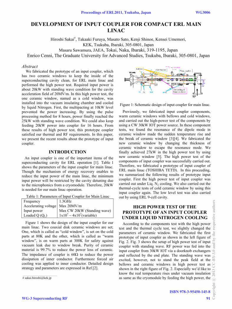
We fabricated the prototype of an input coupler, which has two ceramic windows to keep the inside of the superconducting cavity clean, for ERL main linac and performed the high power test. Required input power is about 20kW with standing wave condition for the cavity acceleration field of 20MV/m. In this high power test, the one ceramic window, named as a cold window, was installed into the vacuum insulating chamber and cooled by liquid Nitrogen. First, the multipacting at 10kW level prevented the power increasing. By using the pulse processing method for 8 hours, power finally reached the 25kW with standing wave condition. We could also keep feeding 20kW power into coupler for 16 hours. From these results of high power test, this prototype coupler satisfied our thermal and RF requirements. In this paper, we present the recent results about the prototype of input coupler.
INTRODUCTION An input coupler is one of the important items of the
superconducting cavity for ERL operation [1]. Table 1 shows the parameters of the input coupler for main linac. Though the mechanism of energy recovery enables to reduce the input power of the main linac, the minimum input power will be restricted by the cavity detuning due to the microphonics from a cryomodule. Therefore, 20kW is needed for our main linac operation.
Table 1: Parameters of Input Coupler for Main Linac Frequency Accelerating voltage Input power Loaded Q (QL)
1.3GHz Max 20MV/m Max CW 20kW (Standing wave) 1x10⁷ ~ 4x10⁷(variable)
Figure 1 shows the design of the input coupler for our main linac. Two coaxial disk ceramic windows are set; One, which is called as “cold window”, is set on the cold parts at 80K and the other, which is called as “warm window”, is on warm parts at 300K for safety against vacuum leak due to window break. Purity of ceramic material is 99.7% to reduce the power loss of ceramic. The impedance of coupler is 60 to reduce the power dissipation of inner conductor. Furthermore forced air cooling was applied to inner conductor. Detailed design strategy and parameters are expressed in Ref.[2].
Figure 1: Schematic design of input coupler for main linac.
Previously, we fabricated input coupler components, warm ceramic windows with bellows and cold windows, and carried out the high-power test of the components by using a CW 30kW IOT power source. In these component tests, we found the resonance of the dipole mode in ceramic window made the sudden temperature rise and the break of ceramic window [3][4]. We fabricated the new ceramic window by changing the thickness of ceramic window to escape the resonance mode. We finally achieved 27kW in the high power test by using new ceramic window [5]. The high power test of the components of input coupler was successfully carried out. Therefore, we fabricated a prototype of input coupler of ERL main linac (TOSHIBA TETD). In this proceeding, we summarized the following results of prototype input coupler. First the high power test of input coupler was carried out under Liq. N2 cooling. We also carried out the thermal-cycle tests of cold ceramic window by using this input coupler again. The low level test was also carried out by using ERL 9-cell cavity.
HIGH POWER TEST OF THE PROTOTYPE OF AN INPUT COUPLER UNDER LIQUID NITROGEN COOLING According to the components test with the high power
test and the thermal cycle test, we slightly changed the parameters of ceramic window. We fabricated the first prototype of input coupler as shown in the left figure of Fig. 2. Fig. 3 shows the setup of high power test of input coupler with standing wave. RF power was fed into the input coupler from 30kW IOT via a doorknob exchangers and reflected by the end plate. The standing wave was excited, however, not to stand the peak field at the bellows and ceramic windows in high power test as shown in the right figure of Fig. 2. Especially we’d like to know the real temperature rises under vacuum insulation as same as the cryomodule by feeding the high power, the
___________________________________________
Proceedings of ERL2011, Tsukuba, Japan WG3006
WG-3 Superconducting RF
ISBN 978-3-95450-145-8
91 Cop
yrig
htc ○
2013
CC
-BY-
3.0
and
byth
ere
spec
tive
auth
ors
LONG-TERM MONITORING OF 3RD-PERIOD EP-ELECTROLYTE IN STF-EP FACILITY AT KEK
M. Sawabe, H. Monjushiro, A. Komiya, M. Satou, T. Saeki, H. Hayano, KEK, Tsukuba, Japan
Abstract We have constructed an Electro-polishing (EP) Facility
in the Superconducting RF Test Facility (STF) at KEK at the end of 2007. We have been operating the EP facility since January 2008 and have performed the EP- processes of cavities about 200 times up to the present. [1, 2]
We changed EP-electrolyte in the 2,000L tank three times until now. And we use the 4th-period EP-electrolyte now. We presented the long-term monitoring result of the 2nd-period EP-electrolyte so far. [3]
In this report, we present the long-term monitoring results of the 3 -period EP-electrolyte, the correlation rd
between EP-process data and the change of fluorine chemical species by EP-electrolyte aging, the result that we could achieve good performance by the EP-electrolyte old enough.
And we want to suggest the new EP chemical equation.
INTRODUCTION The electro-polishing (EP) facilities in KEK were
completed at STF (Super conducting RF Test Facility) area in Dec. 2007. And we have begun to operate in Jan. 2008.
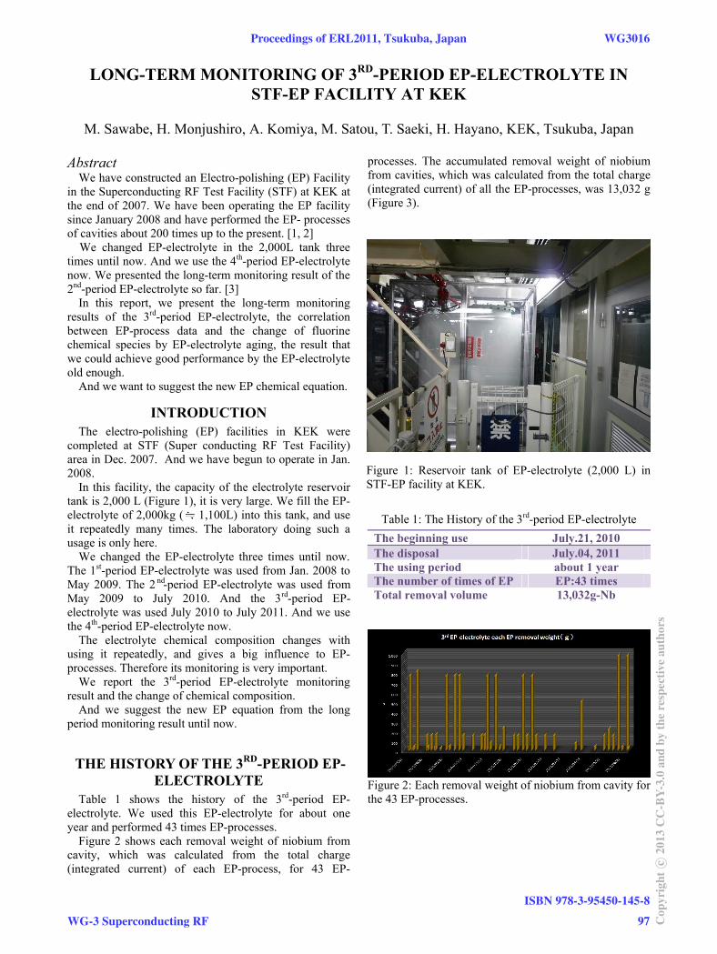
In this facility, the capacity of the electrolyte reservoir tank is 2,000 L (Figure 1), it is very large. We fill the EP-electrolyte of 2,000kg ( 1,100L) into this tank, and use it repeatedly many times. The laboratory doing such a usage is only here.
We changed the EP-electrolyte three times until now. The 1 -period EP-electrolyte was used from Jan. 2008 to st
May 2009. The 2 -period EP-electrolyte was used from nd
May 2009 to July 2010. And the 3 -period EP-rd
electrolyte was used July 2010 to July 2011. And we use the 4th-period EP-electrolyte now.
The electrolyte chemical composition changes with using it repeatedly, and gives a big influence to EP-processes. Therefore its monitoring is very important.
We report the 3rd-period EP-electrolyte monitoring result and the change of chemical composition.
And we suggest the new EP equation from the long period monitoring result until now.
THE HISTORY OF THE 3RD-PERIOD EP-ELECTROLYTE
Table 1 shows the history of the 3rd-period EP-electrolyte. We used this EP-electrolyte for about one year and performed 43 times EP-processes.
Figure 2 shows each removal weight of niobium from cavity, which was calculated from the total charge (integrated current) of each EP-process, for 43 EP-
processes. The accumulated removal weight of niobium from cavities, which was calculated from the total charge (integrated current) of all the EP-processes, was 13,032 g (Figure 3).
Table 1: The History of the 3 -period EP-electrolyte rd
The beginning use July.21, 2010 The disposal July.04, 2011 The using period about 1 year The number of times of EP EP:43 times Total removal volume 13,032g-Nb
Figure 2: Each removal weight of niobium from cavity for the 43 EP-processes.
Figure 1: Reservoir tank of EP-electrolyte (2,000 L) in STF-EP facility at KEK.
Proceedings of ERL2011, Tsukuba, Japan WG3016
WG-3 Superconducting RF
ISBN 978-3-95450-145-8
97 Cop
yrig
htc ○
2013
CC
-BY-
3.0
and
byth
ere
spec
tive
auth
ors

IMPROVED HEAT CONDUCTION FEEDTHROUGHS FOR HOM COUPLERS AT DESY*
J. Sekutowicz DESY, Notkestrasse 85, 22607 Hamburg, Germany
Abstract Vertical acceptance test of 808 cavities of the XFEL
superconducting linac will be conducted for cavities equipped with HOM antennae, mainly to reduce the production and preparation cost. This new procedure is different from that we applied to all superconducting cavities tested in last two decades at DESY. In addition, cw and long pulse operations can be envisioned as complementary modes to the nominal short pulse operation of the XFEL facility. The new vertical test conditions and the new possible operation modes will require better cooling of the HOM couplers. In this contribution we discuss new heating conditions of the HOM antennae and present new feedthrough we ordered for the XFEL cavities.
INTRODUCTION The XFEL cavity and its auxiliaries were designed in
early 90’s for short pulse operation of the superconducting linear collider TESLA. Details of the TESLA cavity have been summarized in the Tesla Technical Design Report [1], which was published in 2001. The proposed duty factor (DF) for the TESLA collider, and presently for XFEL, is ca. 1%. This allows location of the HOM couplers outside liquid helium vessel, as shown in Figure 1. Such a design significantly reduces cost of the cavity and was an unavoidable step for 22 000 cavities of the TESLA main accelerator. Many years of operation of the FLASH linac, at present made of 56 cavities, proved that the TESLA cavity design is well suited for the nominal duty factor of XFEL. Nonetheless, the remarkable continuous improvement in performance of the TESLA cavities, both in gradients and intrinsic quality factors, raises a question, already since several years, whether or not one can increase the DF for XFEL and gain additional flexibility in time structure of the electron and photon beams [2]. As production of the XFEL cavities will begin in 2012, it is still possible to make minor changes in quality of auxiliaries to keep open the possibility of other operation modes with higher DF.
Figure 1: 9-cell TESLA cavity in liquid helium vessel.
VERTICAL ACCEPTANCE TEST Vertical acceptance test for all 808 XFEL cavities will
take place at DESY. The cavities will have attached HOM antennae (feedthroughs) at factories before the test, mainly to lower the production and preparation cost. This new procedure is different from that we applied to all superconducting cavities tested in last two decades at DESY. The standard cw vertical acceptance test, at the specified gradient of 23.4 MV/m, would cause 100 times higher heat load for the antennae than the nominal operation with 1% DF. Unfortunately, unlike the cavity wall, removing that heat from antenna is indirect, and depends on the heat conduction of isolating window and on material it is brazed to. Two measures have been undertaken for the acceptance test to mitigate the excessive overheating.
At first, we decided to test cavities in a pulse mode with DF of ca. 10%. In that way overheating of HOM antennae will be 10 times smaller than in the standard cw vertical test. Secondly, we will replace present HOM feedthroughs with ones having higher heat conduction, because it is expected that heating of HOM antennae could be also a limitation in the linac performance for new operation modes. Design of the new feedthrough will be discuss later, but in general it follows modifications proposed first at TJNAF for cavities developed for the 12 GeV upgrade of CEBAF.
NEW OPERATION MODES OF XFEL LINAC
Two new operation modes of XFEL are at present under discussion; the cw mode and long pulse (lp) mode. In the latter one, the linac will operate with ~100 ms long pulses, which repetition rate is 1 Hz. The intended maximum gradient for the lp mode is close to the present nominal one of 23.4 MV/m. For the cw operation, the cavities will run at 7.5 MV/m at most. Accordingly to our estimation, either of new operations will cause heating of the HOM antenna comparable to that in the pulse acceptance test.
The new modes require new RF-amplifiers with capability to run both in the cw and in long pulse mode. In addition, overall efficiency of the RF-system is an important criterion for choice of the amplifier, especially in case of the lp operation, when at the highest gradient the DF will be ~10%, and thus for 90% of time there will be no beam in the linac. We consider two candidates for the RF-source, either does not take or takes very little energy from the grid when it does not generate RF power. The first is an IOT (Inductive Output Tube), which is a
HOM couplers
Liquid helium vessel
WG3036 Proceedings of ERL2011, Tsukuba, Japan
ISBN 978-3-95450-145-8
102Cop
yrig
htc ○
2013
CC
-BY-
3.0
and
byth
ere
spec
tive
auth
ors
WG-3 Superconducting RF
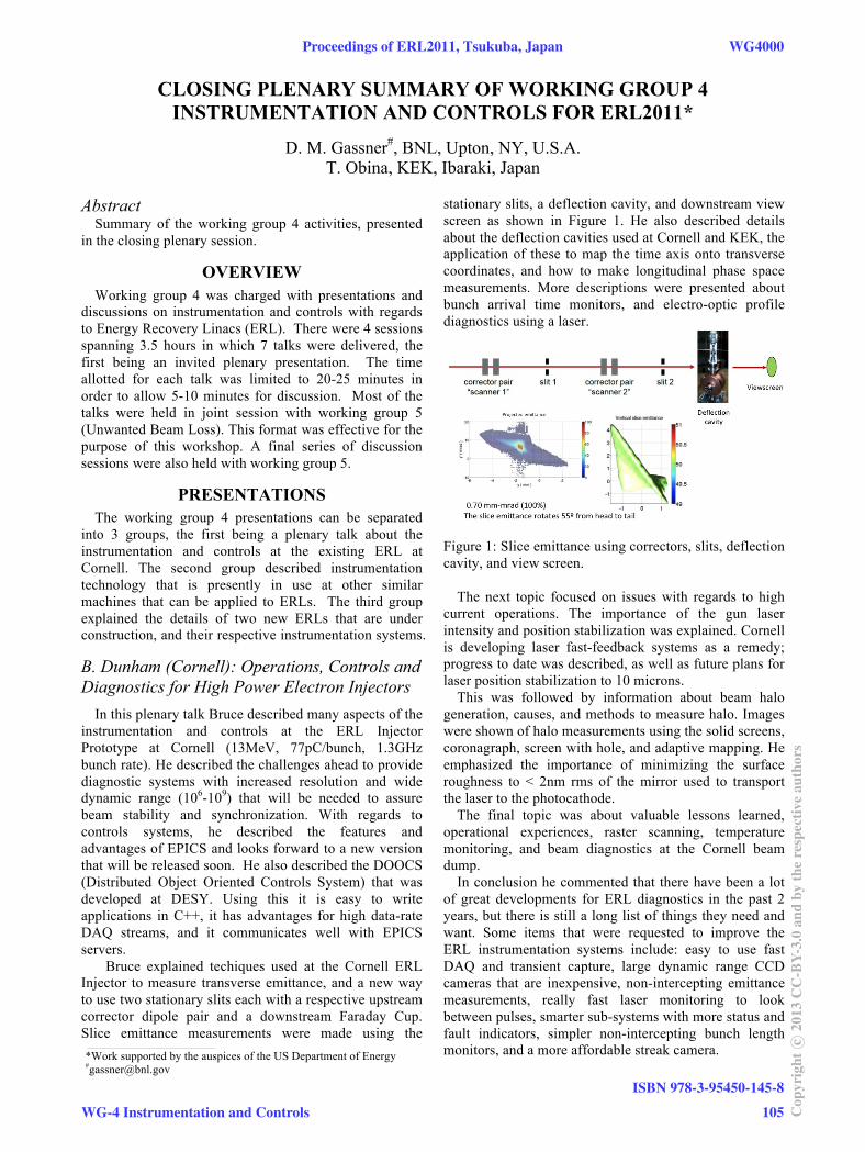
CLOSING PLENARY SUMMARY OF WORKING GROUP 4 INSTRUMENTATION AND CONTROLS FOR ERL2011*
D. M. Gassner#, BNL, Upton, NY, U.S.A. T. Obina, KEK, Ibaraki, Japan
Abstract Summary of the working group 4 activities, presented
in the closing plenary session.
OVERVIEW
Working group 4 was charged with presentations and discussions on instrumentation and controls with regards to Energy Recovery Linacs (ERL). There were 4 sessions spanning 3.5 hours in which 7 talks were delivered, the first being an invited plenary presentation. The time allotted for each talk was limited to 20-25 minutes in order to allow 5-10 minutes for discussion. Most of the talks were held in joint session with working group 5 (Unwanted Beam Loss). This format was effective for the purpose of this workshop. A final series of discussion sessions were also held with working group 5.
PRESENTATIONS The working group 4 presentations can be separated
into 3 groups, the first being a plenary talk about the instrumentation and controls at the existing ERL at Cornell. The second group described instrumentation technology that is presently in use at other similar machines that can be applied to ERLs. The third group explained the details of two new ERLs that are under construction, and their respective instrumentation systems.
B. Dunham (Cornell): Operations, Controls and Diagnostics for High Power Electron Injectors
In this plenary talk Bruce described many aspects of the instrumentation and controls at the ERL Injector Prototype at Cornell (13MeV, 77pC/bunch, 1.3GHz bunch rate). He described the challenges ahead to provide diagnostic systems with increased resolution and wide dynamic range (106-109) that will be needed to assure beam stability and synchronization. With regards to controls systems, he described the features and advantages of EPICS and looks forward to a new version that will be released soon. He also described the DOOCS (Distributed Object Oriented Controls System) that was developed at DESY. Using this it is easy to write applications in C++, it has advantages for high data-rate DAQ streams, and it communicates well with EPICS servers.
Bruce explained techiques used at the Cornell ERL Injector to measure transverse emittance, and a new way to use two stationary slits each with a respective upstream corrector dipole pair and a downstream Faraday Cup. Slice emittance measurements were made using the
stationary slits, a deflection cavity, and downstream view screen as shown in Figure 1. He also described details about the deflection cavities used at Cornell and KEK, the application of these to map the time axis onto transverse coordinates, and how to make longitudinal phase space measurements. More descriptions were presented about bunch arrival time monitors, and electro-optic profile diagnostics using a laser.
Figure 1: Slice emittance using correctors, slits, deflection cavity, and view screen.
The next topic focused on issues with regards to high
current operations. The importance of the gun laser intensity and position stabilization was explained. Cornell is developing laser fast-feedback systems as a remedy; progress to date was described, as well as future plans for laser position stabilization to 10 microns.
This was followed by information about beam halo generation, causes, and methods to measure halo. Images were shown of halo measurements using the solid screens, coronagraph, screen with hole, and adaptive mapping. He emphasized the importance of minimizing the surface roughness to < 2nm rms of the mirror used to transport the laser to the photocathode.
The final topic was about valuable lessons learned, operational experiences, raster scanning, temperature monitoring, and beam diagnostics at the Cornell beam dump.
In conclusion he commented that there have been a lot of great developments for ERL diagnostics in the past 2 years, but there is still a long list of things they need and want. Some items that were requested to improve the ERL instrumentation systems include: easy to use fast DAQ and transient capture, large dynamic range CCD cameras that are inexpensive, non-intercepting emittance measurements, really fast laser monitoring to look between pulses, smarter sub-systems with more status and fault indicators, simpler non-intercepting bunch length monitors, and a more affordable streak camera. ____________________________________________
*Work supported by the auspices of the US Department of Energy #[email protected]
Proceedings of ERL2011, Tsukuba, Japan WG4000
WG-4 Instrumentation and Controls
ISBN 978-3-95450-145-8
105 Cop
yrig
htc ○
2013
CC
-BY-
3.0
and
byth
ere
spec
tive
auth
ors

DESIGN AND PERFORMANCE OF THE SYNCHRONIZATION SYSTEM AND BEAM DIAGNOSTIC INSTRUMENTS FOR SACLA
Hirokazu Maesaka#, Hiroyasu Ego, Chikara Kondo, Takashi Ohshima, Tatsuyuki Sakurai, Yuji Otake, RIKEN SPring-8 Center, 1-1-1 Kouto, Sayo-cho, Sayo-gun, Hyogo, Japan
Naoyasu Hosoda, Shin’ichi Matsubara, Ken’ichi Yanagida, JASRI/SPring-8, 1-1-1 Kouto, Sayo-cho, Sayo-gun, Hyogo, Japan
Shinobu Inoue, SPring-8 Service Co. Ltd., 1-20-5 Kouto, Shingu-cho, Tatsuno-shi, Hyogo, Japan
Abstract In the x-ray free electron laser (XFEL) facility
“SACLA”, stable timing and rf signals with less than 100 fs stability are demanded. In addition, precise beam monitors with micron-meter-level spatial resolution and femtosecond-level temporal resolution are required. For the synchronization, we employed a low-noise master oscillator, an optical rf distribution system, IQ (In-phase and Quadrature) modulators/demodulators etc. For the beam diagnostics, we developed a sub-μm resolution rf cavity BPM, a few-μm resolution beam profile monitor, a C-band transverse rf deflecting structure for a 10 fs resolution temporal bunch structure measurement, etc. We confirmed the performance of these instruments by using an electron beam and finally achieved XFEL lasing in the wavelength region from 0.08 nm to 0.16 nm. Some possible applications of our instruments to an ERL are also discussed.
INTRODUCTION The x-ray free-electron laser (XFEL) facility “SACLA”
(SPring-8 Angstrom Compact Free Electron Laser) is a SASE (Self-Amplified Spontaneous Emission) FEL machine in the wavelength region around 0.1 nm. The construction of SACLA was completed in February, 2011 and the first x-ray lasing was achieved in June, 2011 [1].
The SACLA facility consists of an 8 GeV linear accelerator, in-vacuum undulators and an x-ray beamline, as shown in Fig. 1. An electron beam emitted from a thermionic gun is accelerated up to 8 GeV by 238 MHz, 476 MHz, L-band (1428 MHz), S-band (2856 MHz), and C-band (5712 MHz) accelerators. In the meantime, the temporal bunch length is compressed from 1 ns to 30 fs by three-stage bunch compressors (BC) in order to obtain the demanded peak current of 3 kA. The normalized emittance of the beam is approximately 1 mm mrad. The repetition rate of the accelerator is 60 Hz, synchronized to the AC power line frequency.
For a synchronization issue, the acceleration rf field
should be stable within 1x10⁻⁴ for the amplitude and within 100 fs for the time-equivalent value of a phase. In addition, there are about 70 acceleration rf units and 20 other rf electronics, such as beam monitor circuits and user experiment stations, along the 700 m facility. Therefore, the rf and timing signals should be distributed over 700 m. We use an optical rf and timing distribution system for this demand, because an optical fiber has much smaller attenuation than a coaxial cable. To control the rf field for each accelerator unit precisely, we developed a low-level rf (LLRF) control system. The LLRF system consists of IQ (In-phase and Quadrature) modulators and demodulators, VME D/A and A/D converter boards etc.
For beam diagnostics, high-resolution beam monitors are necessary for both spatial and temporal measurements. The beam position is demanded to be monitored with sub-μm resolution, since an electron beam must be overlapped with x-rays within a few μm in the undulator section to generate SASE-FEL. The spatial resolution of a transverse beam profile image is also required with a few μm to see tiny electron beam of about a 10 μm rms radius. For the temporal profile measurements, the required resolution is 10 fs level, because the bunch length is compressed up to 30 fs.
In this paper, we describe the design and performance of each component in the synchronization and beam diagnostic system. Finally, we discuss possible applications for an ERL.
SYNCHRONIZATION SYSTEM The synchronization system of SACLA [2] can be
divided into an optical rf and timing distribution system and a LLRF system, as illustrated in Fig. 2. In the following subsections, the design and performance of these systems are described. In addition, we developed a special water-cooled enclosure and a low-noise DC power supply to reduce the temperature drift and power supply noise. The performances of these instruments are also described.
_____________ #[email protected] _____________# k @ i 8 j
Figure 1: Schematic layout of the SACLA facility.
WG4001 Proceedings of ERL2011, Tsukuba, Japan
ISBN 978-3-95450-145-8
110Cop
yrig
htc ○
2013
CC
-BY-
3.0
and
byth
ere
spec
tive
auth
ors
WG-4 Instrumentation and Controls
NSLS-II BEAM LOSS MONITOR SYSTEM *
S. L. Kramer#, for the LCM Working Group Brookhaven National Lab., NSLS-II, Upton, NY 11973, U.S.A.
Abstract NSLS-II storage ring is shielded for full injected beam
loss around injection point, with the remainder shielded for significantly lower losses. To insure these design levels aren't exceeded, a Loss Control and Monitoring system (LCM) was designed. The LCM will control and monitor beam losses in the injection region and monitor injection losses outside that region. In order to measure quantitative charge losses, development of new beam loss monitors using Cerenkov light produced by the electron component of the shower induced by beam particles penetrating the vacuum chamber. These Cerenkov beam loss monitors (CBLM) measure the light from electrons passing through ultra-pure fused silica rods placed close to the inner edge of the VC. These rods will give sufficient light signal to monitor beam losses from several particles lost per turn to a major fraction of the 500mA beam in one to a few turns, about a 9 decade dynamic range of signal. Design and measurements of the prototype CBLM system will be presented. Although designed for light sources, CBLMs will provide quantitative beam loss measurements for accelerators with continuous high energy electron beams, such as ERLs.
NSLS-II DESIGN AND SPECIFICATIONS The NSLS-II light source, which has started
construction in FY2009, is a new 3rd generation light source that will replace the two operating 2nd generation light sources at BNL. It has been designed to provide major improvements in the existing beam properties from IR to hard X-rays, with leading edge electron beam properties.
The Storage Ring (SR) is a 30 cell DBA lattice with a super periodicity (SP) of 15, with alternating long (9.3m, LSS) and short (6.6m, SSS) straight sections. The ultra-low emittance (1nm) is obtained not from breaking the achromatic condition for the lattice, but by using a novel approach of increasing the synchrotron radiation damping using damping wigglers, DW, (3-8 7m 1.8T wigglers) in the achromatic straights to reduce the lattice emittance in steps, in addition to the user undulators in the SSS’s[1].
In order to maintain the high brightness for the users, the SR is designed for top-off operation with a minimum injection pulse frequency of one injection per minute, in order to maintain a 1% beam current stability. This requires a full energy booster capable of high injection efficiency.
The SR radiation shield consists of 2-cells (injection and the downstream cell) of heavy concrete shielding capable of shielding the experimental floor from the loss of the full top-off injection beam current. The remainder
of the ring will be shielded for a beam loss rate of up to 1/12th of the top-off injection rate at any one location in the ring. As a consequence of this shielding decision a Loss Control and Monitoring system (LCM)1 has been specified that will control and monitor local beam power losses in all of the accelerators systems to less than the shielding design levels. The LCM will consist of components that will:
1. monitor and limit the beam power losses from the accelerators and transport lines
2. control a major part of beam losses in the SR to the heavily shielded injection region and
3. monitor the SR beam losses in the injection region and account for losses in the remainder of the SR.
LCM SPECIFICATIONS [1] The LCM specifications for the accelerators and beam
transport lines are based on an analysis of the severity of the potential radiation exposure for a particular beam loss scenario which exceeds the shielding design beam loss specification. For the injection systems, the severity of the full beam power lost at any point could be high enough that engineering solutions maybe required. For example, if the full beam power of the booster were lost at any point other than the extraction region, the area above the booster shielding berm would become a high radiation area. The engineering solution is to fence off this area and post a remote area radiation monitor at this location.
The LCM system will monitor the beam current loss (difference between two consecutive current monitors) times the energy of the system transporting that beam (i.e booster dipole or transport dipole field) to determine the beam power lost. If the lost beam power exceeds the shielding design level at that location, then alarms will be issued to operators and the accelerator control system that will require action to reduce the loss level. If corrective action isn’t taken within a specified time period, that insures potential radiation exposures don’t exceed administrative control levels (ACL), then the LCM could prevent injection from continuing. The decisions made by the LCM are not as critical, as the Personal Protective System (PPS) and therefore will be made in a non-safety rated micro-computer that will automatically stop injection if the system fails.
This type of decision will be made for each stage of the injection accelerators and alarms sent when ACL are exceeded or are being approached. The analysis of full injection beam losses in the SR doesn’t result in as high a potential radiation level as in the injector, but will have a risk of greater exposure due to the greater occupancy of the experimental floor. Therefore, in the SR the LCM
1 LCM System was previously called Beam Containment System. ____________________________________________
* Work supported by U.S. DOE, Contract No.DE-AC02-98CH10886 # [email protected]
WG5003 Proceedings of ERL2011, Tsukuba, Japan
ISBN 978-3-95450-145-8
116Cop
yrig
htc ○
2013
CC
-BY-
3.0
and
byth
ere
spec
tive
auth
ors
WG-5 Unwanted Beam Loss
BRIEF REVIEW OF THE APPROACHES TO ELUCIDATE THE MECHANISM OF THE RADIATION-INDUCED DEMAGNETIZATION
T. Bizen#, JASRI/SPring-8, Hyogo, Japan
Abstract Permanent magnets decrease their magnetic field
under severe radiation environment. This radiation damage, radiation-induced demagnetization, is a great concern especially for the devices that requires very precise uniform magnetic field such as undulators. The evaluation of this field degradation is difficult because the mechanism of the radiation–induced demagnetization is not clear. Several approaches to clarify this mechanism have been made. For example, (1) the approach to examine the relations between the field degradation and the environmental factors like magnet shape, temperature and so on, (2) the approach to examine the changes of the microstructures and the properties of the magnet after irradiation, (3) the approach to compare and examine the experiments of the demagnetization and the computer simulations of the radiation. This paper reviews and summarizes these approaches and models briefly. The new point of view to consider the mechanism is presented as well.
INTRODUCTION The magnetic field intensity of the permanent magnet
decreases when the magnets are used in a strong radiation environment. This radiation damage is called radiation-induced demagnetization. The degradation of the magnetic field is a big problem for undulators and other devices with magnet that requires precise magnetic field. The changes of the magnetic field in the undulators were observed in the storage ring in APS[1]. For this reason, many studies have been done so far. In this paper, I review and summarize the typical studies and propose the new point of view to consider the mechanism of the radiation-induced demagnetization.
APPROACHES TO CLARIFY THE MECHANISM
Several approaches to clarify the mechanism of the radiation-induced demagnetization have been made. For example, (1) the approach to examine the relations between the field degradation and the environmental factors like magnet shape, temperature and so on, (2) the approach to examine the changes of the properties and the microstructures of the magnet after irradiation, (3) the approach to compare and examine the experiments of the demagnetization and the computer simulations of the radiation.
Environmental Factors The radiation-induced demagnetization shows the
dependencies of the following environmental factors; (a)
material, chemical component, microstructure and manufacture, (b) coercivity, (c) temperature, (d) permeance coefficient that relate to magnet shape, outer magnetic field, inflection point (shape of B-H curve).
The relation of these factors looks uncertain, but these factors are similar to the factors that influence the demagnetization originated from the reversal magnetization. Especially, (b), (c), (d) are related to the coercivity decrease caused by the internal magnetic field that is described by permeance coefficient.
Properties and Microstructures after Irradiation Several researchers have tried to observe the changes
in the irradiated magnets. Cost[2], Kähkönen[3], Okuda[4], Ito[5], Chen[6], Klaffky[7], and Qiu[8] examined the magnetic properties change. The damaged magnets by irradiation were remagnetized and compared the magnetic properties before irradiation. Chen observed that the recovery intensity of the remanence changed depending on the flux of a 10 MeV neutron. Qiu observed the degradation of the remanence by a 2.5 GeV electron irradiation. However, others found no changes in the remanence. Cost observed the 20 % increase of the coercivity by fast neutron irradiation. Klaffky performed a thermal neutron irradiation, and Qiu performed a 2.5 GeV electron irradiation. Though both found no changes in coercivity.
Talvite[9] and Gao[10] could not observe any microstructural changes in the magnets after irradiation by using the positron annihilation measurement or the X-ray diffraction. Yang[11, 12] found some atomic local changes by using the XAS, Mössbauer spectrometry and XAFS.
These results indicate that the radiation-induced demagnetization can occur without clear changes of the magnetic properties and the structures. The change is extremely local even if existing. This implies that the cause of the radiation-induced demagnetization in early stage should be the magnetization reversal.
Experiments and Computer Simulation Qiu, Asano and Leitner calculated the particle
transport and interactions with matter using Monte Carlo simulation FLUKA, and compared the experimental results of the radiation-induced demagnetization.
Qiu[8] calculated the absorbed dose and the 1 MeV equivalent neutron fluence. “1 MeV equivalent neutron fluence, is widely used to characterize the displacement damage of the electronic devices in which the main material is Si when they are irradiated by neutrons.” Qiu analysed the demagnetization caused by a 2.5 GeV electron irradiation, and proposed the fitted formula composed of two terms, the dose and the 1 MeV ____________________________________________
Proceedings of ERL2011, Tsukuba, Japan WG5005
WG-5 Unwanted Beam Loss
ISBN 978-3-95450-145-8
121 Cop
yrig
htc ○
2013
CC
-BY-
3.0
and
byth
ere
spec
tive
auth
ors
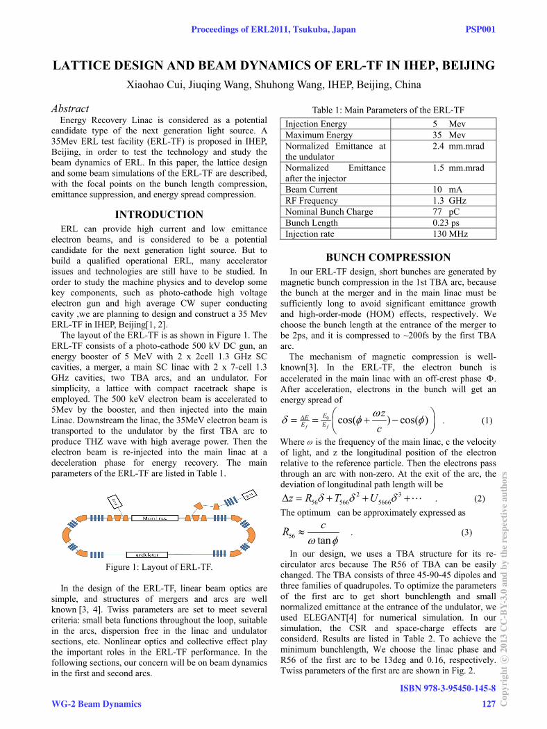
LATTICE DESIGN AND BEAM DYNAMICS OF ERL-TF IN IHEP, BEIJING
Xiaohao Cui, Jiuqing Wang, Shuhong Wang, IHEP, Beijing, China
Abstract Energy Recovery Linac is considered as a potential
candidate type of the next generation light source. A 35Mev ERL test facility (ERL-TF) is proposed in IHEP, Beijing, in order to test the technology and study the beam dynamics of ERL. In this paper, the lattice design and some beam simulations of the ERL-TF are described, with the focal points on the bunch length compression, emittance suppression, and energy spread compression.
INTRODUCTION ERL can provide high current and low emittance
electron beams, and is considered to be a potential candidate for the next generation light source. But to build a qualified operational ERL, many accelerator issues and technologies are still have to be studied. In order to study the machine physics and to develop some key components, such as photo-cathode high voltage electron gun and high average CW super conducting cavity ,we are planning to design and construct a 35 Mev ERL-TF in IHEP, Beijing[1, 2].
The layout of the ERL-TF is as shown in Figure 1. The ERL-TF consists of a photo-cathode 500 kV DC gun, an energy booster of 5 MeV with 2 x 2cell 1.3 GHz SC cavities, a merger, a main SC linac with 2 x 7-cell 1.3 GHz cavities, two TBA arcs, and an undulator. For simplicity, a lattice with compact racetrack shape is employed. The 500 keV electron beam is accelerated to 5Mev by the booster, and then injected into the main Linac. Downstream the linac, the 35MeV electron beam is transported to the undulator by the first TBA arc to produce THZ wave with high average power. Then the electron beam is re-injected into the main linac at a deceleration phase for energy recovery. The main parameters of the ERL-TF are listed in Table 1.
Figure 1: Layout of ERL-TF.
In the design of the ERL-TF, linear beam optics are
simple, and structures of mergers and arcs are well known [3, 4]. Twiss parameters are set to meet several criteria: small beta functions throughout the loop, suitable in the arcs, dispersion free in the linac and undulator sections, etc. Nonlinear optics and collective effect play the important roles in the ERL-TF performance. In the following sections, our concern will be on beam dynamics in the first and second arcs.
Table 1: Main Parameters of the ERL-TF
Injection Energy 5 Mev Maximum Energy 35 Mev Normalized Emittance at the undulator
2.4 mm.mrad
Normalized Emittance after the injector
1.5 mm.mrad
Beam Current 10 mA RF Frequency 1.3 GHz Nominal Bunch Charge 77 pC Bunch Length 0.23 ps Injection rate 130 MHz
BUNCH COMPRESSION In our ERL-TF design, short bunches are generated by
magnetic bunch compression in the 1st TBA arc, because the bunch at the merger and in the main linac must be sufficiently long to avoid significant emittance growth and high-order-mode (HOM) effects, respectively. We choose the bunch length at the entrance of the merger to be 2ps, and it is compressed to ~200fs by the first TBA arc.
The mechanism of magnetic compression is well- known[3]. In the ERL-TF, the electron bunch is accelerated in the main linac with an off-crest phase . After acceleration, electrons in the bunch will get an energy spread of
0 cos( ) cos( )f f
EEE E
zc
. (1)
Where is the frequency of the main linac, c the velocity of light, and z the longitudinal position of the electron relative to the reference particle. Then the electrons pass through an arc with non-zero. At the exit of the arc, the deviation of longitudinal path length will be
2 356 566 5666z R T U . (2)
The optimum can be approximately expressed as
56 tan
cR
. (3)
In our design, we uses a TBA structure for its re-circulator arcs because The R56 of TBA can be easily changed. The TBA consists of three 45-90-45 dipoles and three families of quadrupoles. To optimize the parameters of the first arc to get short bunchlength and small normalized emittance at the entrance of the undulator, we used ELEGANT[4] for numerical simulation. In our simulation, the CSR and space-charge effects are considerd. Results are listed in Table 2. To achieve the minimum bunchlength, We choose the linac phase and R56 of the first arc to be 13deg and 0.16, respectively. Twiss parameters of the first arc are shown in Fig. 2.
Proceedings of ERL2011, Tsukuba, Japan PSP001
WG-2 Beam Dynamics
ISBN 978-3-95450-145-8
127 Cop
yrig
htc ○
2013
CC
-BY-
3.0
and
byth
ere
spec
tive
auth
ors
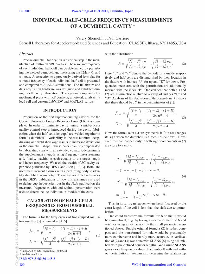
INDIVIDUAL HALF-CELLS FREQUENCY MEASUREMENTSOF A DUMBBELL CAVITY ∗
Valery Shemelin† , Paul CarriereCornell Laboratory for Accelerator-based Sciences and Education (CLASSE), Ithaca, NY 14853,USA
AbstractPrecise dumbbell fabrication is a critical step in the man-
ufacture of multi-cell SRF cavities. The resonant frequency
of each individual half-cell can be determined by perturb-
ing the welded dumbbell and measuring the TM010 0- and
π-mode. A correction to a previously derived formulae for
π-mode frequency of each individual half-cell is presented
and compared to SLANS simulations. The RF fixture and
data acquisition hardware was designed and validated dur-
ing 7-cell cavity fabrication. The system comprised of a
mechanical press with RF contacts, a network analyzer, a
load cell and custom LabVIEW and MATLAB scripts.
INTRODUCTIONProduction of the first superconducting cavities for the
Cornell University Energy Recovery Linac (ERL) is com-
plete. In order to minimize cavity tuning, a mid-process
quality control step is introduced during the cavity fabri-
cation when the half-cells (or cups) are welded together to
form a dumbbell”. Variability in the raw niobium, deep-
drawing and weld shrinkage results in increased deviations
in the dumbbell shape. These errors can be compensated
by fabricating cups with an extended equators, determining
the supplementary length using frequency measurements
and, finally, machining each equator to the target length
and hence frequency. We used the wealth of SC cavity ex-
perience published by DESY and JLab [1, 2, 3]. Both labs
used measurement fixtures with a perturbing body to iden-
tify dumbbell asymmetry. There are no direct references
in the DESY publications of how this asymmetry is used
to define cup frequencies, but in the JLab publication the
measured frequencies with and without perturbation were
used to determine the individual π-modes of the cups.
CALCULATION OF HALF-CELLSFREQUENCIES FROM DUMBBELL
MEASUREMENTSThe formula for the frequencies of two coupled oscilla-
tors used by [3] is derived in [4, 5]:
fπ,U =
√f2π + f2
0
2+
(f2π − f2
0 ) · (2 +R)
2√R+ 4
,
fπ,D =
√f2π + f2
0
2+
(f2π − f2
0 ) · (2−R)
2√R+ 4
,
(1)
∗Supported by NSF award DMR-0807731† [email protected]
with the substitution
R =
√f2π − f2
π,P,U
f2π − f2
π,P,D
−√
f20 − f2
0,P,U
f20 − f2
0,P,D
. (2)
Here “0” and “π” denote the 0-mode or π-mode respec-
tively and half-cells are distinguished by their location in
the fixture with indices “U” for up and “D” for down. Fre-
quencies measured with the perturbation are additionally
marked with the index “P”. One can see that both (1) and
(2) are asymmetric relative to a swap of indices “U” and
“D”. Analysis of the derivation of the formula in [4] shows
that there should be R2 in the denominators of (1):
f∗π,U =
√f2π + f2
0
2+
(f2π − f2
0 ) · (2 +R)
2√R2 + 4
,
f∗π,D =
√f2π + f2
0
2+
(f2π − f2
0 ) · (2−R)
2√R2 + 4
.
(3)
Now, the formulae in (3) are symmetric if R in (2) changes
its sign when the dumbbell is turned upside-down. How-
ever, this can happen only if both right components in (2)
are close to a unity:
R =
√f2π − f2
π,P,U
f2π − f2
π,P,D
−√
f20 − f2
0,P,U
f20 − f2
0,P,D
≈
≈ (1 + α)− (1 + β) = α− β,
R′ =
√f2π − f2
π,P,D
f2π − f2
π,P,U
−√
f20 − f2
0,P,D
f20 − f2
0,P,U
≈
≈ 1
1 + α− 1
1 + β≈ β − α ≈ −R.
(4)
This, in its turn, can happen when the shift caused by the
extra length of the cell is less than the shift due to pertur-
bation.
One could transform the formula for R so that it would
be symmetrical, e. g. by taking a mean arithmetic of R and
−R′, or using an expansion by the small parameter men-
tioned above. But the original formula (2) is rather com-
pact and the transformed formula would be presumably
more cumbersome and hardly more accurate. A verifica-
tion of (2) and (3) was done with SLANS [6] using a dumb-
bell with pre-defined equator lengths. We assume SLANS
gives exact frequency values of a dumbbell with and with-
out perturbations. We can also determine the relationship
“
PSP007 Proceedings of ERL2011, Tsukuba, Japan
ISBN 978-3-95450-145-8
130Cop
yrig
htc ○
2013
CC
-BY-
3.0
and
byth
ere
spec
tive
auth
ors
WG-4 Instrumentation and Controls
CHARGE LIFETIME, EMITTANCE, AND SURFACE ANALYSIS STUDIES OF PHOTOCATHODE IN A JLAB DC HIGH VOLTAGE GUN*
J. L. McCarter#, University of Virginia, Charlottesville, VA 22904, U.S.A. T. Rao, J. Smedley, BNL, Upton, NY 11973, U.S.A.
R. Mammei, M. Poelker, R. Suleiman, TJNAF, Newport News, VA 23606, U.S.A.
Abstract For the past year, BNL and JLab groups have been
collaborating to study the characteristics of K2CsSb photocathodes inside a DC high voltage photogun. Although the first set of runs at 1 mA and at 100 kV bias voltage indicated disappointing charge lifetime, comparable to values obtained with GaAs photocathodes, subsequent measurements indicate that both the QE and charge life time increased significantly. This improvement could be attributed to the change in the chemical composition of the cathode due to UV irradiation. The charge life time measurements do not indicate any QE decay for currents of 10 mA with 350 micron FWHM spot, slight decay at 16 mA and significant decay at 20 mA for this spot size. When the spot size was increased to 850 micron, the lifetime at 20 mA increased significantly, implying local heating due to high laser intensity. Additional measurements with laser alone, without the HV, support this argument. These results as well as emittance and surface science measurements will be presented.
INTRODUCTION Photoelectron guns are well suited to provide the high
brightness, and often high average current, electron beams required for light sources and energy recovery LINAC accelerator applications. Two popular photocathode choices are GaAs:Cs and K2CsSb. The GaAs:Cs photocathode can exhibit very high QE and can produce a beam with small thermal emittance [1]; however, it requires strict adherence to procedures that limit the effects of its fragility. Once inside the photogun, GaAs is prone to rapid QE loss that can result from many situations such as poor vacuum and field emission. The K2CsSb photocathode can exhibit high QE has complications of its own in practice. GaAs can be purchased from numerous reliable vendors while the K2CsSb photocathode is an amorphous compound that must be grown while in vacuum via successive application of the elemental species on a suitable substrate and then transported and installed into the photogun also entirely under vacuum. Consistent results depend on consistent adherence to proper growth procedures. While the K2CsSb photocathode has larger thermal emittance [1,2] as compared to GaAs:Cs, it is considered to be a prompt emitter because of its positive electron affinity nature, producing shorter bunches than
GaAs:Cs. The biggest advantage of K2CsSb however is the photocathode’s ability to survive under markedly harsher vacuum conditions as compared to GaAs:Cs.
The purpose of this work was to expand on prior measurements done on the performance of a K2CsSb photocathode. The performance directly compares to that of GaAs:Cs, which was characterized in the same 100kV DC photogun [3]. Early results indicated that the charge lifetime while illuminated at 532nm was no better than GaAs [4]; however after a major vacuum event, the lifetime at 440nm greatly improved, along with the QE of almost the entire photocathode [5]. This work revisits the initial lifetime results at 532nm and measures the beam emittance, as well as provides some insight into what factors affect the performance of a K2CsSb cathode by using SEM techniques.
EQUIPMENT K2CsSb was grown at BNL on a JLab style
photocathode puck [6] and was then transported via car to JLab, roughly 450 miles away, in an ultrahigh vacuum transfer vessel (10-11 Torr). After growth at BNL, the K2CsSb photocathode was installed in the DC high voltage photogun within approximately 2.5 days. No appreciable QE decay was observed, which indicates a very long dark lifetime.
Cathode Fabrication The K2CsSb cathode was prepared at BNL in a UHV
chamber by depositing sequentially high purity Sb, K and Cs onto a puck, similar to the standard JLab puck but made of aluminium with a thin layer of stainless steel (SS) explosion bonded to the top surface to accept the coating. Stainless steel was chosen as previous measurements at BNL indicate it provides high QE at 532 nm. Two sequential depositions were executed on the same substrate, as the first evaporation did not produce satisfactory QE. Specifics to the BNL K2CsSb deposition system and process can be found in these proceedings [7]. During the second evaporation process the potassium dispenser was prematurely exhausted, which decreased the expected QE at wavelengths above 300nm [4, 5].
Load- Lock DC High Voltage Photogun The CEBAF load-locked DC photogun [6] is composed
of four vacuum chambers separated by all-metal gate valves: the high voltage chamber, where the electron
___________________________________________
*Work supported by the U.S. DOE under Contracts No. DE-AC05-84ER40150 and DE-AC02-98CH10886 and partially by DE-FG02-97ER41025. # [email protected]
K2CsSb
Proceedings of ERL2011, Tsukuba, Japan PSP019
WG-1 Electron Sources
ISBN 978-3-95450-145-8
133 Cop
yrig
htc ○
2013
CC
-BY-
3.0
and
byth
ere
spec
tive
auth
ors
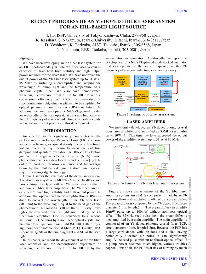
RECENT PROGRESS OF AN -DOPED FIBER LASER SYSTEM FOR AN ERL-BASED LIGHT SOURCE
I. Ito, ISSP, University of Tokyo, Kashiwa, Chiba, 277-8581, Japan R. Kasahara, S. Nakamura, Ibaraki University, Hitachi, Ibaraki, 316-8511, Japan
D. Yoshitomi, K. Torizuka, AIST, Tsukuba, Ibaraki, 305-8568, Japan N. Nakamura, KEK, Tsukuba, Ibaraki, 305-0801, Japan
Abstract We have been developing an Yb fiber laser system for
an ERL photocathode gun. The Yb fiber laser system is expected to have both high stability and high output power required for the drive laser. We have improved the output power of the Yb fiber laser system up to 31 W at 85 MHz by installing a preamplifier and keeping the wavelength of pump light and the temperature of a photonic crystal fiber. We also have demonstrated wavelength conversion from 1 μm to 800 nm with a conversion efficiency of 9.5% by generating a supercontinuum light, which is planned to be amplified by optical parametric amplification (OPA) in future. In addition, we are developing a Nd:YVO4-based mode-locked oscillator that can operate at the same frequency as the RF frequency of a superconducting accelerating cavity. We report our recent progress in this development.
INTRODUCTION
An electron source significantly contributes to the performance of an Energy Recovery Linac (ERL) because an electron beam goes around it only one or a few times not to reach the equilibrium between the radiation damping and quantum excitation. A 500kV DC electron gun with a negative electron affinity (NEA) GaAs photocathode is being developed as an ERL gun [1,2]. In order to produce ultra-low emittance and high-charge beam by the photocathode gun, a drive laser system requires leading-edge technology.
Figure 1 shows the schematic of the drive laser system. The drive laser system is MOPA (Master Oscillator and Power Amplifier) type with an Yb fiber laser oscillator and two Yb fiber laser amplifiers. The Yb fiber laser is expected to have high stability and high output power. In addition, the optical parametric amplification (OPA) is done to convert the wavelength of the Yb fiber laser (1030nm) to the wavelength equal to the band gap of the photocathode NEA-GaAs (700-800nm). Firstly, two lights are diverged from the light amplified by the Yb fiber laser amplifier. One is converted to a second harmonic (SH, 515nm) by a nonlinear optical crystal and the other to a supercontinuum light (SC, 800±50nm) by a high nonlinear photonic crystal fiber (PCF). Finally, OPA is done using SH as the pumping light and SC as the seed light.
In this paper, we report the development of the Yb fiber laser amplifier and the demonstration experiment of wavelength conversion from 1 μm to 800 nm by the
supercontinuum generation. Additionally we report the development of a Nd:YVO4-based mode-locked oscillator that can operate at the same frequency as the RF frequency of a superconducting accelerating cavity.
∼
Figure 1: Schematic of drive laser system.
LASER AMPLIFIER We previously developed an Yb doped phonic crystal
fiber laser amplifier and amplified an 85MHz seed pulse up to 10W [3]. This time, we have improved the output power of the amplifier system up to 31 W at 85 MHz.
Figure 2: Schematic of Yb fiber laser amplifier system. Figure 2 shows the schematic of the Yb fiber laser
amplifier system. An 85MHz seed pulse is made by an Yb fiber oscillator and amplified to 60mW by a preamplifier. The preamplifier is composed by the Yb doped fiber (core diameter:5 μm, length:5m). The preamplifier can amplify 10mW pulse up to 100mW without nonlinear optical effect. The 85MHz seed pulse from the preamplifier is then amplified by a main amplifier. The main amplifier is composed of an Yb doped photonic crystal fiber (PCF, core diameter: 40μm, length:1.2m). Because the PCF has a large core doped with Yb ions and a clad having periodically allocated air holes, it can significantly amplify the seed pulse without nonlinear optical effect. If a pump power becomes much higher, various troubles happen. First of all, the PCF is at risk of burning by much
Yb
Proceedings of ERL2011, Tsukuba, Japan PSP020
WG-1 Electron Sources
ISBN 978-3-95450-145-8
137 Cop
yrig
htc ○
2013
CC
-BY-
3.0
and
byth
ere
spec
tive
auth
ors
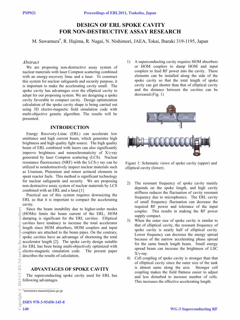
DESIGN OF ERL SPOKE CAVITY FOR NON-DESTRUCTIVE ASSAY RESEARCH
M. Sawamura#, R. Hajima, R. Nagai, N. Nishimori, JAEA, Tokai, Ibaraki 319-1195, Japan
Abstract We are proposing non-destructive assay system of
nuclear materials with laser Compton scattering combined with an energy-recovery linac and a laser. To construct this system for nuclear safeguards and security purpose, it is important to make the accelerating cavity small. The spoke cavity has advantages over the elliptical cavity to adopt for our proposing system. We are designing a spoke cavity favorable to compact cavity. Design optimization calculation of the spoke cavity shape is being carried out using 3D electro-magnetic field simulation code with multi-objective genetic algorithm. The results will be presented.
INTRODUCTION Energy Recovery-Linac (ERL) can accelerate low
emittance and high current beam, which generates high brightness and high quality light source. The high quality beam of ERL combined with lasers can also significantly improve brightness and monochromaticity of X/-ray generated by laser Compton scattering (LCS). Nuclear resonance fluorescence (NRF) with the LCS- ray can be utilized to nondestructively inspect nuclear materials such as Uranium, Plutonium and minor actinoid elements in spent reactor fuels. This method is significant technology for nuclear safeguards and security. We are proposing non-destructive assay system of nuclear materials by LCS combined with an ERL and a laser.[1]
Practical use of this system requires downsizing the ERL so that it is important to compact the accelerating cavity.
Since the beam instability due to higher-order modes (HOMs) limits the beam current of the ERL, HOM damping is significant for the ERL cavities. Elliptical cavities have tendency to increase the total accelerator length since HOM absorbers, HOM couplers and input couplers are attached to the beam pipes. On the contrary, spoke cavities have an advantage of shortening the total accelerator length [2]. The spoke cavity design suitable for ERL has been being multi-objectively optimized with electro-magnetic simulation code. The present paper describes the results of calculation.
ADVANTAGES OF SPOKE CAVITY The superconducting spoke cavity used for ERL has
following advantages.
1) A superconducting cavity requires HOM absorbers or HOM couplers to damp HOM and input couplers to feed RF power into the cavity. These elements can be installed along the side of the spoke cavity so that the total length of spoke cavity can get shorter than that of elliptical cavity and the distance between the cavities can be decreased.(Fig. 1)
2) The resonant frequency of spoke cavity mainly
depends on the spoke length, and high cavity stiffness reduces the fluctuation of cavity resonant frequency due to microphonics. The ERL cavity of small frequency fluctuation can decrease the required RF power and tolerance of the input coupler. This results in making the RF power supply compact.
3) When the outer size of spoke cavity is similar to that of elliptical cavity, the resonant frequency of spoke cavity is nearly half of elliptical cavity. Lower frequency can decrease the energy spread because of the narrow accelerating phase spread for the same bunch length beam. Small energy spread beam can increase the brightness of LSC X/-ray.
4) Cell coupling of spoke cavity is stronger than that of elliptical cavity since the outer size of the tank is almost same along the axis. Stronger cell coupling makes the field flatness easier to adjust and less disturbed to increase number of cells. This increases the effective accelerating length.
Figure 1: Schematic views of spoke cavity (upper) and elliptical cavity (lower).
___________________________________________ #[email protected]
PSP021 Proceedings of ERL2011, Tsukuba, Japan
ISBN 978-3-95450-145-8
140Cop
yrig
htc ○
2013
CC
-BY-
3.0
and
byth
ere
spec
tive
auth
ors
WG-3 Superconducting RF