An Open Avionics and Software Architecture to Support ...
23
An Open Avionics and Software Architecture to Support Future NASA Exploration Missions IEEE MetroCon 2017 October 26, 2017 1 Adam Schlesinger, Deputy Manager, AES Avionics & Software NASA-Johnson Space Center (JSC), Houston, TX
Transcript of An Open Avionics and Software Architecture to Support ...

An Open Avionics and
Software Architecture to
Support Future NASA
Exploration Missions
IEEE MetroCon 2017
October 26, 2017
1
Adam Schlesinger, Deputy Manager, AES Avionics & Software
NASA-Johnson Space Center (JSC), Houston, TX

NASA’s Exploration Roadmap
Using the International Space Station
Operating in the Lunar Vicinity (proving ground)
After 2030
Leaving the Earth-Moon System and Reaching Mars Orbit
Now
2020s
Phase 0
Continue research and testing on ISS to solve exploration challenges. Evaluate potential for lunar resources. Develop standards.
Phase 1
Begin missions in cislunar space. Build Deep Space Gateway. Initiate assembly of Deep Space Transport.
Phase 2
Complete Deep Space Transport and conduct yearlong Mars simulation mission.
Phases 3 and 4
Begin sustained crew expeditions to Martian system and surface of Mars.
EXPANDING HUMAN PRESENCE IN PARTNERSHIPCREATING ECONOMIC OPPORTUNITIES, ADVANCING TECHNOLOGIES, AND ENABLING DISCOVERY
2
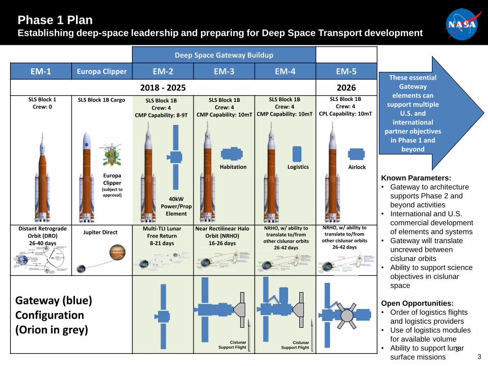
Phase 1 PlanEstablishing deep-space leadership and preparing for Deep Space Transport development
3
Deep Space Gateway Buildup
EM-1 Europa Clipper EM-2 EM-3 EM-4 EM-5
2018 - 2025 2026
Gateway (blue) Configuration (Orion in grey)
Distant Retrograde Orbit (DRO)26-40 days
Multi-TLI Lunar Free Return
8-21 days
SLS Block 1Crew: 0
40kWPower/Prop
Element
Airlock
Jupiter Direct
SLS Block 1B Cargo
NRHO, w/ ability to translate to/from
other cislunar orbits26-42 days
Near Rectilinear Halo Orbit (NRHO)
16-26 days
Europa Clipper
(subject to approval)
SLS Block 1BCrew: 4
CMP Capability: 8-9T
SLS Block 1BCrew: 4
CMP Capability: 10mT
SLS Block 1BCrew: 4
CMP Capability: 10mT
Habitation
These essential Gateway
elements can support multiple
U.S. and international
partner objectives in Phase 1 and
beyond
SLS Block 1BCrew: 4
CPL Capability: 10mT
Logistics
NRHO, w/ ability to translate to/from
other cislunar orbits26-42 days
Cislunar
Support FlightCislunar
Support Flight
Known Parameters:
• Gateway to architecture
supports Phase 2 and
beyond activities
• International and U.S.
commercial development
of elements and systems
• Gateway will translate
uncrewed between
cislunar orbits
• Ability to support science
objectives in cislunar
space
Open Opportunities:
• Order of logistics flights
and logistics providers
• Use of logistics modules
for available volume
• Ability to support lunar
surface missions 3
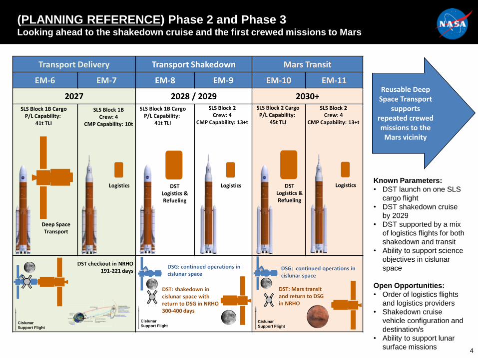
(PLANNING REFERENCE) Phase 2 and Phase 3Looking ahead to the shakedown cruise and the first crewed missions to Mars
4
Transport Delivery Transport Shakedown Mars Transit
EM-6 EM-7 EM-8 EM-9 EM-10 EM-11
2027 2028 / 2029 2030+
DST checkout in NRHO191-221 days
Deep Space Transport
SLS Block 1BCrew: 4
CMP Capability: 10t
Logistics
SLS Block 1B CargoP/L Capability:
41t TLI
DST Logistics &Refueling
SLS Block 1B CargoP/L Capability:
41t TLI
SLS Block 2Crew: 4
CMP Capability: 13+t
Logistics
Reusable Deep Space Transport
supports repeated crewed missions to the
Mars vicinity
DST Logistics &Refueling
Logistics
DSG: continued operations in cislunar space
SLS Block 2 CargoP/L Capability:
45t TLI
SLS Block 2Crew: 4
CMP Capability: 13+t
Known Parameters:
• DST launch on one SLS
cargo flight
• DST shakedown cruise
by 2029
• DST supported by a mix
of logistics flights for both
shakedown and transit
• Ability to support science
objectives in cislunar
space
Open Opportunities:
• Order of logistics flights
and logistics providers
• Shakedown cruise
vehicle configuration and
destination/s
• Ability to support lunar
surface missions
DST: shakedown in cislunar space with return to DSG in NRHO300-400 days
Cislunar
Support Flight
DSG: continued operations in cislunar space
DST: Mars transit and return to DSG in NRHO
Cislunar
Support FlightCislunar
Support Flight
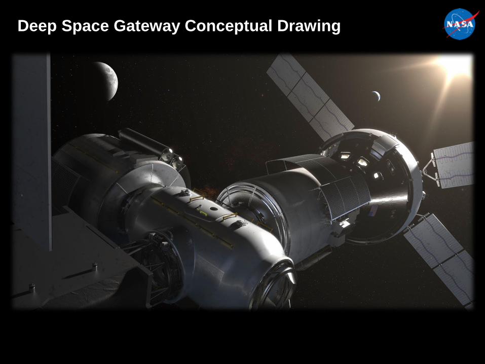
Deep Space Gateway Conceptual Drawing
5
Advanced Exploration Systems (AES) Division
• NASA's Advanced Exploration Systems (AES) division is pioneering
innovative approaches and public-private partnerships to rapidly develop
prototype systems, advance key capabilities, and validate operational
concepts for future human missions beyond Earth orbit
• AES activities are related to crew mobility, habitation, vehicle systems,
robotic precursors, and foundational systems for deep space
• AES infuses new technologies developed by the Space Technology
Mission Directorate and partners with the Science Mission Directorate to
address Strategic Knowledge Gaps for multiple destinations
• AES is leading NASA’s Deep-Space Gateway & Transport (DSG&T) Efforts
6

AES Avionics & Software (A&S) Project
• AES Avionics & Software (A&S) Project Goal:
– Define and exercise an avionics architecture that is open-source, highly reliable with
fault tolerance, and utilizes standard capabilities and interfaces, which are scalable
and customizable to support future exploration missions
• A&S Drivers:
– Technology Transparency
• The underlying hardware should not have any impact on an application either during
development or execution
• Code reuse and portability
– Reliability and Maintenance
• Operate in the presence of failures so that Maintenance Free Operating Periods (MFOPS)
can be achieved
• Provide autonomous operations
• Minimal number of unique spares
– Incremental Update & Certification - Designed for Growth and Change
• Applications can be inserted/altered with minimum impact on other systems and on the
supporting safety case
• Flexible scheduling to meet the deadlines of all the applications for each viable
configuration and when system is upgraded
7

AES Avionics & Software (A&S) Project
• A&S Focus Areas and Objectives:
– Command & Data Handling (C&DH) - Define a reliable, high-performance
& modular C&DH architecture and build HW catalog
– Software - Provide a reusable software architecture and tools suitable for
human-rated missions
– Human Interfaces - Identify, integrate & test human interface technologies
that are scalable, sustainable, and evolvable to support future exploration
– Communication and Wireless Systems - Enable interoperable, wireless
& networked communication for inter/intra-vehicle systems
– Systems Engineering and Integration (SE&I) - Model, build & test
flexible and robust integrated vehicle systems
• A&S Benefits:
– Results in an open architecture that allows use of hardware from multiple
vendors
– Enables use of evolving (near-launch) technology
– Ability to upgrade capabilities and infuse new technologies with cost
effective validation
8
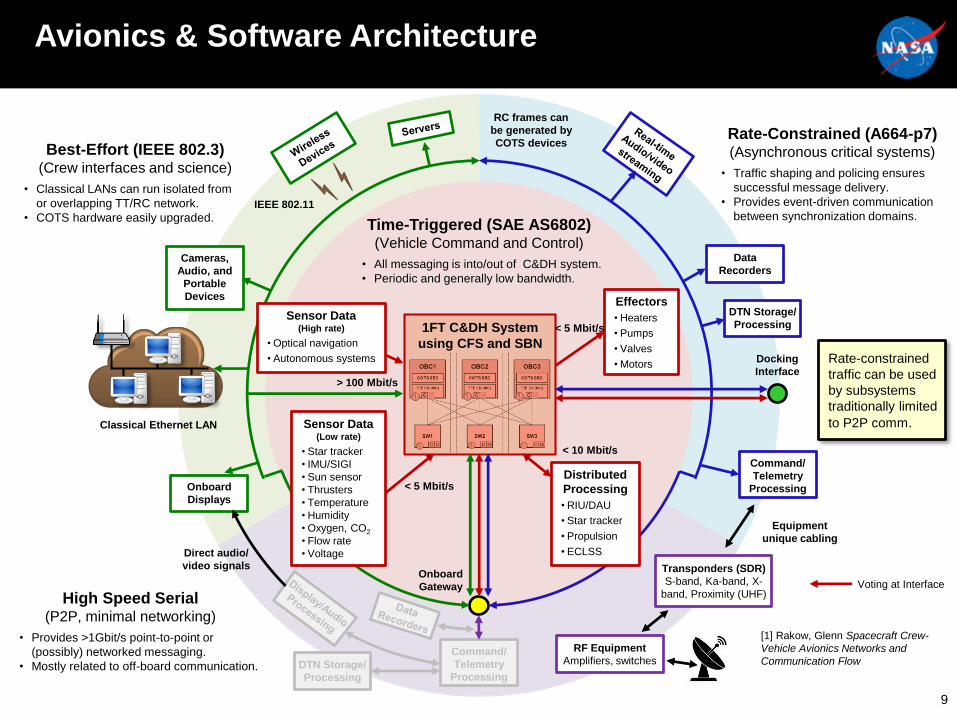
Avionics & Software Architecture
9
Time-Triggered (SAE AS6802)(Vehicle Command and Control)
Effectors
• Heaters
• Pumps
• Valves
• Motors
• All messaging is into/out of C&DH system.
• Periodic and generally low bandwidth.
< 5 Mbit/s
> 100 Mbit/s
< 10 Mbit/s
Onboard
Gateway
Docking
Interface
1FT C&DH System
using CFS and SBN
Rate-Constrained (A664-p7)(Asynchronous critical systems)
• Traffic shaping and policing ensures
successful message delivery.
• Provides event-driven communication
between synchronization domains.
RC frames can
be generated by
COTS devices
Command/
Telemetry
Processing
DTN Storage/
Processing
Data
Recorders
Distributed
Processing
• RIU/DAU
• Star tracker
• Propulsion
• ECLSS
Best-Effort (IEEE 802.3)(Crew interfaces and science)
• Classical LANs can run isolated from
or overlapping TT/RC network.
• COTS hardware easily upgraded.
Onboard
Displays
Classical Ethernet LAN
IEEE 802.11
Cameras,
Audio, and
Portable
Devices
Sensor Data(High rate)
• Optical navigation
• Autonomous systems
Sensor Data(Low rate)
• Star tracker
• IMU/SIGI
• Sun sensor
• Thrusters
• Temperature
• Humidity
• Oxygen, CO2
• Flow rate
• Voltage
High Speed Serial(P2P, minimal networking)
• Provides >1Gbit/s point-to-point or
(possibly) networked messaging.
• Mostly related to off-board communication.
Command/
Telemetry
ProcessingDTN Storage/
Processing
Direct audio/
video signals Transponders (SDR)
S-band, Ka-band, X-
band, Proximity (UHF)
RF Equipment
Amplifiers, switches
Equipment
unique cabling
[1] Rakow, Glenn Spacecraft Crew-
Vehicle Avionics Networks and
Communication Flow
Voting at Interface
Rate-constrained
traffic can be used
by subsystems
traditionally limited
to P2P comm.
< 5 Mbit/s
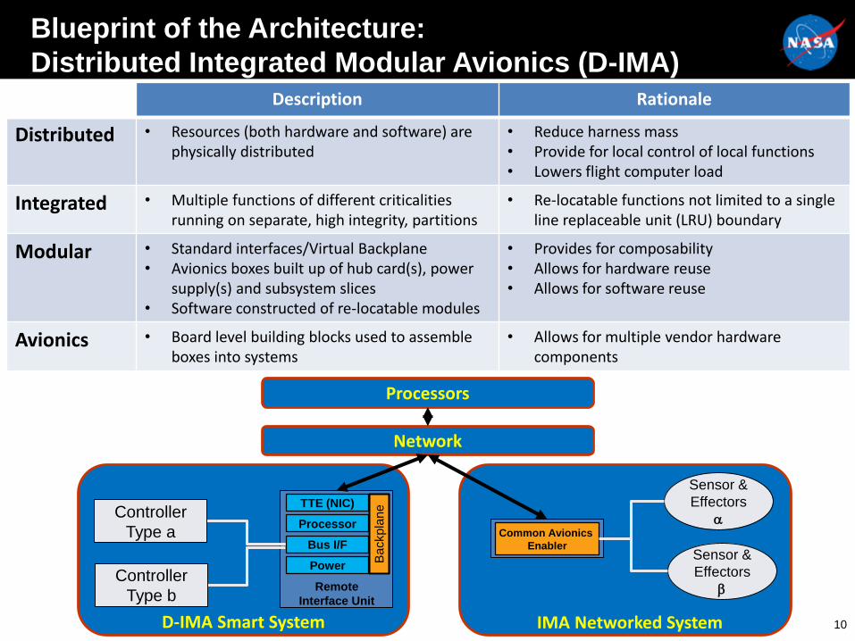
Blueprint of the Architecture:
Distributed Integrated Modular Avionics (D-IMA)
10
Description Rationale
Distributed • Resources (both hardware and software) are physically distributed
• Reduce harness mass• Provide for local control of local functions• Lowers flight computer load
Integrated • Multiple functions of different criticalities running on separate, high integrity, partitions
• Re-locatable functions not limited to a single line replaceable unit (LRU) boundary
Modular • Standard interfaces/Virtual Backplane• Avionics boxes built up of hub card(s), power
supply(s) and subsystem slices• Software constructed of re-locatable modules
• Provides for composability• Allows for hardware reuse• Allows for software reuse
Avionics • Board level building blocks used to assemble boxes into systems
• Allows for multiple vendor hardware components
TTE (NIC)
Processor
Power
Remote
Interface Unit
D-IMA Smart System
Ba
ckp
lan
e
IMA Networked System
Sensor &
Effectors
Sensor &
Effectors
Controller
Type a
Controller
Type b
Bus I/FCommon Avionics
Enabler
Network
Processors
Brain of the Architecture:
NASA’s Core Flight Software (CFS)
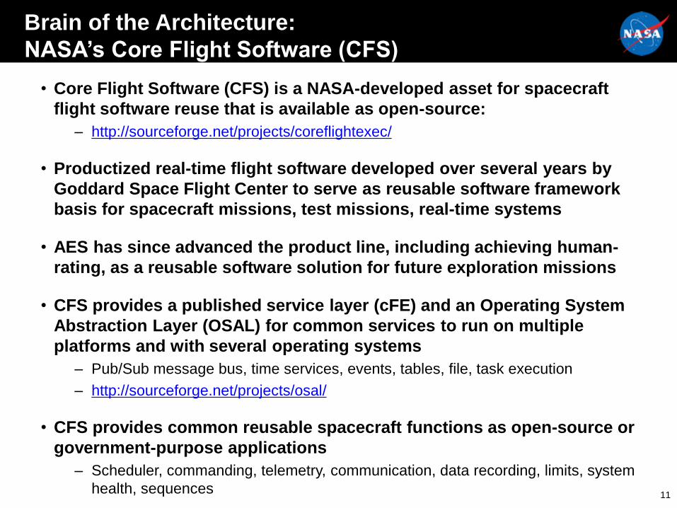
• Core Flight Software (CFS) is a NASA-developed asset for spacecraft
flight software reuse that is available as open-source:
– http://sourceforge.net/projects/coreflightexec/
• Productized real-time flight software developed over several years by
Goddard Space Flight Center to serve as reusable software framework
basis for spacecraft missions, test missions, real-time systems
• AES has since advanced the product line, including achieving human-
rating, as a reusable software solution for future exploration missions
• CFS provides a published service layer (cFE) and an Operating System
Abstraction Layer (OSAL) for common services to run on multiple
platforms and with several operating systems
– Pub/Sub message bus, time services, events, tables, file, task execution
– http://sourceforge.net/projects/osal/
• CFS provides common reusable spacecraft functions as open-source or
government-purpose applications
– Scheduler, commanding, telemetry, communication, data recording, limits, system
health, sequences11
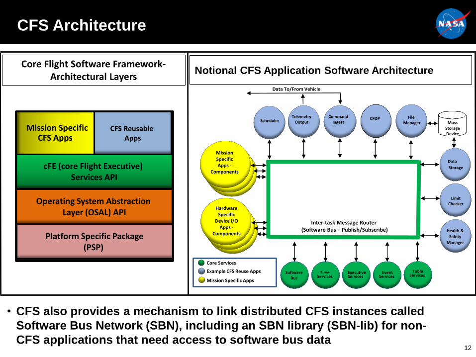
CFS Architecture
12
Notional CFS Application Software Architecture
EventServices
ExecutiveServices
TimeServices
Inter-task Message Router (Software Bus – Publish/Subscribe) Health &
Safety
Manager
SoftwareBus
Data
Storage
TableServices
MassStorageDevice
CFDP
Data To/From Vehicle
SchedulerCommand
IngestTelemetry
OutputFile
Manager
MissionSpecificApps -
Components
HardwareSpecific
Device I/OApps -
Components
Mission Specific Apps
Core Services
Example CFS Reuse Apps
LimitChecker
cFE (core Flight Executive) Services API
CFS Reusable Apps
Mission Specific CFS Apps
Core Flight Software Framework-Architectural Layers
Operating System Abstraction Layer (OSAL) API
Platform Specific Package(PSP)
• CFS also provides a mechanism to link distributed CFS instances called
Software Bus Network (SBN), including an SBN library (SBN-lib) for non-
CFS applications that need access to software bus data

Some CFS Supported Platforms: Non-Exhaustive
13
• CFS has been ported to work on many processors…
• …and with many operating systems, both real- and non-real-time
LEON3
AITECH SP0-100 Intel x86
BAE RAD750
Maxwell SCS750
Space Micro Proton 400K Raspberry Pi

Backbone of the Architecture:
Time-Triggered Ethernet
• Time-Triggered Ethernet (TTE) is compatible with, can coexist with on the same physical media,
and expands classical Ethernet with services to meet time-critical or deterministic conditions,
supporting three message types:
• Time-triggered (SAE AS6802): Sent over the network at predefined times and take precedence
over all other message types
– Occurrence, delay and precision of messages are predefined and guaranteed
• Rate-constrained (ARINC 664 p7): Used for applications with less stringent determinism and
real-time requirements
– Bandwidth is predefined and guaranteed for each application and delays/jitter have defined limits
• Best-effort (IEEE 802.3): Follow classical Ethernet policy
– Use the remaining network bandwidth and have lower priority than TT or RC messages
• TTE Standards exist or are in-work and NASA supports development of an open TTE Standard
– SAE AS6802 – Time-Triggered Ethernet
– European Cooperation for Space Standardization (ECSS) ECSS-E-ST-50-16 – Time-Triggered Ethernet
– Consultative Committee for Space Data Systems (CCSDS) Sub-Network Services WG
14
Sikorsky S-97 RAIDER NASA’s Orion Spacecraft

Reliability and Robustness:
Triplex Voting Architecture
15
• Developed a 1-Byzantine Fault tolerant
voting architecture using TTE and CFS
using current COTS technologies
• Three Onboard Computers (OBC)
• Three High-Integrity (command/monitor) TTE
Switches
• Remote Interface Units (RIU)
• Architecture is scalable through
additional network planes, high-integrity
devices, etc.
• Approach uses TTE for data distribution
and sync and built CFS apps to do so
C M
C M
C M
• Benefits of the voting architecture:
• Enables the use of COTS single board computers
• Eliminates need for separate cross-channel data link
• Eliminates need for separate timing hardware
• Paper: “A Proposed Byzantine Fault-Tolerant Voting
Architecture using Time-Triggered Ethernet”
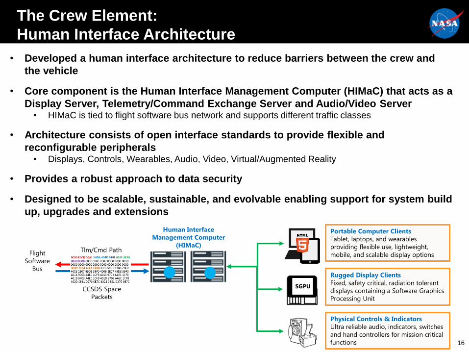
Human Interface
Management Computer
(HIMaC)
Portable Computer Clients
Tablet, laptops, and wearables
providing flexible use, lightweight,
mobile, and scalable display options
Rugged Display Clients
Fixed, safety critical, radiation tolerant
displays containing a Software Graphics
Processing Unit
Physical Controls & Indicators
Ultra reliable audio, indicators, switches
and hand controllers for mission critical
functions
SGPUCCSDS Space
Packets
Tlm/Cmd PathFlight
Software
Bus
• Developed a human interface architecture to reduce barriers between the crew and
the vehicle
• Core component is the Human Interface Management Computer (HIMaC) that acts as a
Display Server, Telemetry/Command Exchange Server and Audio/Video Server• HIMaC is tied to flight software bus network and supports different traffic classes
• Architecture consists of open interface standards to provide flexible and
reconfigurable peripherals• Displays, Controls, Wearables, Audio, Video, Virtual/Augmented Reality
• Provides a robust approach to data security
• Designed to be scalable, sustainable, and evolvable enabling support for system build
up, upgrades and extensions
The Crew Element:
Human Interface Architecture
16

Can You Hear Me Now?:
Wireless and Communication Architecture
17
• The communication links that the architecture is designed to support include:
• DSG ↔ Earth
• DSG ↔ Lunar Surface
• DSG ↔ Visiting Vehicle
• DSG ↔ Proximity/Wireless Communications (i.e. Extra-Vehicular Activity (EVA))
• Architecture supports several standard wireless standards and technologies for
internal spacecraft and proximity communications
– IEEE 802.11 Family
– 5G Technology (LTE)
– Wireless Sensor Networks
– Radio Frequency Identification (RFID) for both logistics and sensing
• Candidate standards and technologies have been identified, are still being
evaluated, and have not been finalized
– Optical communication is also being looked at for DSG
• Will leverage the Interagency Operations Advisory Group (IOAG) Service Catalog and Consultative Committee for Space Data Systems (CCSDS) Standards
• Internetworking capabilities are a requirement, and must operate in the presence of time delays and outages
– Delay/Disruption Tolerant Networking (DTN) is the solution

Connecting to the Solar System Internet (SSI):
Delay/Disruption Tolerant Networking (DTN)
18
• Delay/Disruption Tolerant Networking (DTN) is an AES developed protocol suite that extends the
terrestrial Internet capabilities into highly stressed data communication environments where the
conventional Internet does not work
– These environments are typically subject to frequent disruptions, unidirectional/asymmetric links,
long delays and high error rates
• DTN is being standardized by the Consultative Committee for Space Data Systems (CCSDS) and
the Internet Engineering Task Force (IETF) DTN Working Groups
• NASA’s Interplanetary Overlay Network (ION) DTN implementation is open-source software:
– https://sourceforge.net/projects/ion-dtn/files/
• Some of the benefits of DTN include improved operations and situational awareness,
interoperability and reuse, space link efficiency, utilization and robustness, security and quality-
of-service

Putting it All Together:
Systems Engineering and Integration (SE&I)
• Determined the necessary avionics functions for architecture, allocated the functions to
abstract systems and implemented the systems to perform the functions
• Modeled the avionics and software architecture using Model-Based Systems Engineering
(MBSE) tools using the Systems Modelling Language (SysML) throughout life-cycle
• Led the migration of other spacecraft subsystems to run CFS applications on path-to-flight
processors and connect to the architecture
– Power, Environmental Control and Life Support System (ECLSS), Vehicle Autonomy applications, etc.
• Conceptualized mission scenarios to exercise/stress the architecture through both
simulation and testing
19
An Enabling Architecture:
Supporting Future Autonomous Systems
• As human exploration moves farther out into space, the need for autonomous systems
significantly increases
– Many functions of the current Mission Control Center (MCC) will need to move onto the spacecraft
• AES, STMD and others within NASA are researching various autonomy applications that
could be used as part of the Deep-Space Gateway and Transport efforts
• NASA is also closely tracking commercial developments that could support autonomous
systems
– AI and Cognitive Computing, Deep-Learning Algorithms, Model-based Condition Monitoring, Industrial and
Home Automation, IoT, etc.
• The developed avionics and software architecture will serve as a platform to exercise
autonomy applications and concepts
– Exercise onboard autonomous Integrated Vehicle Health Management (IVHM) applications
– Explore distributed and centralized autonomy concepts
– Build crew and ground operator familiarity and comfort with autonomy applications
– Provide reliable command/control capabilities for spacecraft subsystems
– Provide additional processing/storage for less-capable systems
– Monitor subsystems and serve as an operations advisor
• Open architecture will also serve as a technology development platform to help establish
partnerships and collaborations to further enhance architecture
– Support Academia, International Partner or commercial technologies
20

Avionics & Software Architecture
21
Time-Triggered (SAE AS6802)(Vehicle Command and Control)
Effectors
• Heaters
• Pumps
• Valves
• Motors
• All messaging is into/out of C&DH system.
• Periodic and generally low bandwidth.
< 5 Mbit/s
> 100 Mbit/s
< 10 Mbit/s
Onboard
Gateway
Docking
Interface
1FT C&DH System
using CFS and SBN
Rate-Constrained (A664-p7)(Asynchronous critical systems)
• Traffic shaping and policing ensures
successful message delivery.
• Provides event-driven communication
between synchronization domains.
RC frames can
be generated by
COTS devices
Command/
Telemetry
Processing
DTN Storage/
Processing
Data
Recorders
Distributed
Processing
• RIU/DAU
• Star tracker
• Propulsion
• ECLSS
Best-Effort (IEEE 802.3)(Crew interfaces and science)
• Classical LANs can run isolated from
or overlapping TT/RC network.
• COTS hardware easily upgraded.
Onboard
Displays
Classical Ethernet LAN
IEEE 802.11
Cameras,
Audio, and
Portable
Devices
Sensor Data(High rate)
• Optical navigation
• Autonomous systems
Sensor Data(Low rate)
• Star tracker
• IMU/SIGI
• Sun sensor
• Thrusters
• Temperature
• Humidity
• Oxygen, CO2
• Flow rate
• Voltage
High Speed Serial(P2P, minimal networking)
• Provides >1Gbit/s point-to-point or
(possibly) networked messaging.
• Mostly related to off-board communication.
Command/
Telemetry
ProcessingDTN Storage/
Processing
Direct audio/
video signals Transponders (SDR)
S-band, Ka-band, X-
band, Proximity (UHF)
RF Equipment
Amplifiers, switches
Equipment
unique cabling
[1] Rakow, Glenn Spacecraft Crew-
Vehicle Avionics Networks and
Communication Flow
Voting at Interface
Rate-constrained
traffic can be used
by subsystems
traditionally limited
to P2P comm.
< 5 Mbit/s
Key Takeaways
• The AES A&S project has developed an Avionics & Software
architecture that is:
– Open-source, with standard capabilities and interfaces
– Highly reliable with 1-Byzantine fault tolerance
– Scalable and customizable to support future exploration missions such as the
Deep Space Gateway and Transport
– Built on a foundation of NASA’s Core Flight Software (CFS) and Time-Triggered
Ethernet (TTE)
– Realizable with currently available COTS technology and supports multi-vendor
hardware
– Fully modeled in SysML, implemented and tested in relevant environments
– Designed to support various autonomy technologies that will be needed for deep-
space human exploration22

23