An Onboard Monocular Vision System for Autonomous Takeo ...
13
An Onboard Monocular Vision System for Autonomous Takeoff, Hovering and Landing of a Micro Aerial Vehicle Shaowu Yang, Sebastian A. Scherer and Andreas Zell Abstract—In this paper, we present an onboard monocular vision system for autonomous takeoff, hovering and landing of a Micro Aerial Vehicle (MAV). Since pose information with metric scale is critical for autonomous flight of a MAV, we present a novel solution to six degrees of freedom (DOF) pose estimation. It is based on a single image of a typical landing pad which consists of the letter “H” surrounded by a circle. A vision algorithm for robust and real-time landing pad recognition is implemented. Then the 5 DOF pose is estimated from the elliptic projection of the circle by using projective geometry. The remaining geometric ambiguity is resolved by incorporating the gravity vector estimated by the inertial measurement unit (IMU). The last degree of freedom pose, yaw angle of the MAV, is estimated from the ellipse fitted from the letter “H”. The efficiency of the presented vision system is demonstrated comprehensively by comparing it to ground truth data provided by a tracking system and by using its pose estimates as control inputs to autonomous flights of a quadrotor. I. INTRODUCTION Autonomous flight of Unmanned Aerial Vehicles (UAVs) has attracted much research during the past years. Takeoff, hovering and landing are three basic phases for autonomous flight of rotorcrafts. Among them, autonomous landing on a specified target is especially complex because it requires robust recognition of the landing pad and precise position control. Micro unmanned Aerial Vehicles (MAVs) are limited in onboard computational power and payload, thus the ability for onboard sensing and control of these phases turns out to be a challenge. Compared with other sensors, cameras have a supe- rior potential for environment perception and are usually lightweight. Thus, many UAVs rely on vision systems for autonomous flight tasks, especially in GPS-denied envi- ronments, e.g. in indoor applications. For the control of autonomous flight of a MAV, metric pose estimation is essential, which could be provided by stereo cameras. But for a MAV, monocular vision is more compact and less compu- tationally intensive. Monocular vision, however, poses more challenges for pose estimation with metric scale, especially for hovering above or landing on a specified target. In this paper, we present an onboard monocular vision so- lution for the full 6 DOF pose estimation of a MAV. A typical landing pad for rotorcrafts with the letter “H” surrounded by a circle can be robustly recognized by the proposed object S. Yang and S. A. Scherer are PhD students with the Chair of Cognitive Systems, Department of Computer Science, University of T¨ ubingen, Sand 1, D-72076 T¨ ubingen, Germany {shaowu.yang, sebastian.scherer}@uni-tuebingen.de A. Zell is full professor with the Chair of Cognitive Systems, Department of Computer Science, University of T¨ ubingen, Sand 1, D-72076 T¨ ubingen, Germany [email protected] recognition algorithm, even in cluttered environments. Then the 5 DOF pose of the MAV, its 3D position, roll and pitch angles, is estimated from the projection of the known circle, and the remaining degree of freedom pose, the yaw angle, from the projection of the letter “H”. No additional metric scale measurement sensor is needed for pose estimation. As MAVs are nearly always equipped with an IMU, we use its gravity vector measurement as reference data in the 5 DOF pose estimation step. The 3D position and yaw angle estimates are then used as input to a nested PID controller which is used to control hovering of the MAV above the landing pad. Takeoff and landing on the landing pad are achieved by using the proposed point setting approach. II. RELATED WORK Previous work on visually guided takeoff, hovering and landing of UAVs is mainly focused on the landing problem, as it is the most difficult of the three phases. Two main categories of visual landing systems exist for rotorcraft UAVs, being used both on large scale helicopters with a high payload and on MAVs with a very limited payload. The first one is for landing a UAV on a predefined target [20][17][14][23], which requires precise pose estimation of the UAV relative to the target. The second category is for landing on a suitable area [11][3], which uses vision for the detection of a good enough place for landing. Saripalli et al. [20] solved the landing task of a helicopter quite early by using image moments for object recognition and estimating the relative position to the landing pad with precise height of the helicopter provided by differential GPS. But the proposed approach would hardly work in cluttered or GPS-denied environments. A special landing pad with five circle triplets in different sizes was designed by Merz et al. [17]. And three ellipses in the image, i.e. the projections of three circles of this pad are used for estimating the relative pose in a coarse-to-fine process. Lange et al. [14] achieved autonomous landing and position control of a MAV by estimating the 3D position from a landing pad consisting of several concentric circles, assuming that the UAV is flying exactly parallel to the landing pad and the ground plane. Wenzel et al. [22] presented a low-cost solution for visual tracking a landing place by using a Wii remote infrared camera and four infrared LED markers. In [23], they achieved takeoff, hovering and landing of a MAV on a moving platform. Xu et al. [24] also use a cooperative object and an infrared camera for pose estimation of UAVs, but only the yaw angle is computed.
Transcript of An Onboard Monocular Vision System for Autonomous Takeo ...

An Onboard Monocular Vision System for Autonomous Takeoff,Hovering and Landing of a Micro Aerial Vehicle
Shaowu Yang, Sebastian A. Scherer and Andreas Zell
Abstract— In this paper, we present an onboard monocularvision system for autonomous takeoff, hovering and landing of aMicro Aerial Vehicle (MAV). Since pose information with metricscale is critical for autonomous flight of a MAV, we present anovel solution to six degrees of freedom (DOF) pose estimation.It is based on a single image of a typical landing pad whichconsists of the letter “H” surrounded by a circle. A visionalgorithm for robust and real-time landing pad recognitionis implemented. Then the 5 DOF pose is estimated from theelliptic projection of the circle by using projective geometry. Theremaining geometric ambiguity is resolved by incorporatingthe gravity vector estimated by the inertial measurement unit(IMU). The last degree of freedom pose, yaw angle of theMAV, is estimated from the ellipse fitted from the letter “H”.The efficiency of the presented vision system is demonstratedcomprehensively by comparing it to ground truth data providedby a tracking system and by using its pose estimates as controlinputs to autonomous flights of a quadrotor.
I. INTRODUCTION
Autonomous flight of Unmanned Aerial Vehicles (UAVs)has attracted much research during the past years. Takeoff,hovering and landing are three basic phases for autonomousflight of rotorcrafts. Among them, autonomous landing ona specified target is especially complex because it requiresrobust recognition of the landing pad and precise positioncontrol. Micro unmanned Aerial Vehicles (MAVs) are limitedin onboard computational power and payload, thus the abilityfor onboard sensing and control of these phases turns out tobe a challenge.
Compared with other sensors, cameras have a supe-rior potential for environment perception and are usuallylightweight. Thus, many UAVs rely on vision systems forautonomous flight tasks, especially in GPS-denied envi-ronments, e.g. in indoor applications. For the control ofautonomous flight of a MAV, metric pose estimation isessential, which could be provided by stereo cameras. But fora MAV, monocular vision is more compact and less compu-tationally intensive. Monocular vision, however, poses morechallenges for pose estimation with metric scale, especiallyfor hovering above or landing on a specified target.
In this paper, we present an onboard monocular vision so-lution for the full 6 DOF pose estimation of a MAV. A typicallanding pad for rotorcrafts with the letter “H” surrounded bya circle can be robustly recognized by the proposed object
S. Yang and S. A. Scherer are PhD students with the Chairof Cognitive Systems, Department of Computer Science, Universityof Tubingen, Sand 1, D-72076 Tubingen, Germany {shaowu.yang,sebastian.scherer}@uni-tuebingen.de
A. Zell is full professor with the Chair of Cognitive Systems, Departmentof Computer Science, University of Tubingen, Sand 1, D-72076 Tubingen,Germany [email protected]
recognition algorithm, even in cluttered environments. Thenthe 5 DOF pose of the MAV, its 3D position, roll and pitchangles, is estimated from the projection of the known circle,and the remaining degree of freedom pose, the yaw angle,from the projection of the letter “H”. No additional metricscale measurement sensor is needed for pose estimation. AsMAVs are nearly always equipped with an IMU, we useits gravity vector measurement as reference data in the 5DOF pose estimation step. The 3D position and yaw angleestimates are then used as input to a nested PID controllerwhich is used to control hovering of the MAV above thelanding pad. Takeoff and landing on the landing pad areachieved by using the proposed point setting approach.
II. RELATED WORK
Previous work on visually guided takeoff, hovering andlanding of UAVs is mainly focused on the landing problem,as it is the most difficult of the three phases. Two maincategories of visual landing systems exist for rotorcraftUAVs, being used both on large scale helicopters with ahigh payload and on MAVs with a very limited payload.The first one is for landing a UAV on a predefined target[20][17][14][23], which requires precise pose estimation ofthe UAV relative to the target. The second category is forlanding on a suitable area [11][3], which uses vision for thedetection of a good enough place for landing.
Saripalli et al. [20] solved the landing task of a helicopterquite early by using image moments for object recognitionand estimating the relative position to the landing pad withprecise height of the helicopter provided by differentialGPS. But the proposed approach would hardly work incluttered or GPS-denied environments. A special landing padwith five circle triplets in different sizes was designed byMerz et al. [17]. And three ellipses in the image, i.e. theprojections of three circles of this pad are used for estimatingthe relative pose in a coarse-to-fine process. Lange et al.[14] achieved autonomous landing and position control ofa MAV by estimating the 3D position from a landing padconsisting of several concentric circles, assuming that theUAV is flying exactly parallel to the landing pad and theground plane. Wenzel et al. [22] presented a low-cost solutionfor visual tracking a landing place by using a Wii remoteinfrared camera and four infrared LED markers. In [23],they achieved takeoff, hovering and landing of a MAV ona moving platform. Xu et al. [24] also use a cooperativeobject and an infrared camera for pose estimation of UAVs,but only the yaw angle is computed.

The core of these vision systems for takeoff, hovering andlanding of UAVs with respect to a predefined target is toprovide pose estimation with metric scale for the positioncontrol of the UAVs. This can actually be done with onecircular pad. The geometry of the image projection of acircle, which is an ellipse in the general case, is well studiedin the area of projective geometry [10][13][5]. But thisdoes not mean that the pose estimation from the previouswork can be directly used for control of autonomous flightapplications because there is a common geometric ambiguityin these approaches, where two possible solutions can beobtained, i.e. the absolute solution cannot be achieved fromone image projection of one circle. This is similar to thework of Chen et al. [4] for camera calibration, which usestwo coplanar circles. Recently, Eberli et al. [7] presented avision algorithm which is able to estimate the 5 DOF poseof a MAV by using two concentric circles with very differentradii. But this algorithm does not work when the camera is inan upright position above the circle mark [7], so the attitudeestimation from the IMU is directly used for the 3D positioncomputation in their work.
In our work, we solve the 5 DOF pose estimation prob-lem based on one image projection of one circle, using aprojective geometry method with a simple algebraic form.The gravity vector estimated by the IMU is used only as areference for solving the geometric ambiguity inherited fromthe projective geometry. Furthermore, we extend this to 6DOF pose estimation by using the ellipse fitted to the contourof the projected letter “H” for yaw angle computation. Thepresented algorithm is demonstrated to be sufficient for thecontrol of autonomous takeoff, hovering and landing of aMAV.
III. EXPERIMENTAL SETUP
A. Quadrotor Platform
In this work, we use the open source MAV platformdeveloped by the Pixhawk team at ETH Zurich describedin [15]. As shown in Fig. 1, it is a quadrotor equipped withfour motors and 10” propellers, enabling it to lift about 400gof payload at a total system weight of about 1.2 kg, includingbattery. Its onboard computer is a Kontron microETXexpresscomputer-on-module (COM) featuring an Intel Core 2 DUO1.86 GHz CPU, 2 GB DDR3 RAM and a 16 Gb SSD.The pxIMU inertial measurement unit/autopilot board weuse mainly consists of a MCU and sensors including anaccelerometer and a gyroscope. The MCU is a 60 MHzARM7 microcontroller for sensor readout and fusion as wellas position and attitude control. The accelerometer and thegyroscope provide the 3D linear acceleration (±6g) and the3D angular velocity (±500 deg/s). A PointGrey Firefly MVmonochrome camera of only 37g weight, with the resolutionof 640×480, a maximum frame rate of 60 fps, and a lens withview angle of 90 degrees, is mounted looking downwards.
B. Landing Pad
The landing pad is printed on an A4 paper for theexperiments, as shown in Fig. 1. The radius of the outer
Fig. 1: The quadrotor platform and the landing pad. Thecorresponding coordinate systems are also plotted.
boundary of the circle is 90 mm. A larger radius would leadto a larger working distance for the vision system, but wouldlead to a larger “blind” range, in which the camera cannotobserve the circle.
C. External Tracking System
To measure ground truth data of the 6 DOF pose of thequadrotor, we use an external tracking system, ”Optitrack”by Naturalpoint1, which includes 12 infrared cameras. Afterwe attach six markers to the quadrotor, it can provide 6 DOFpose estimates of the quadrotor with a speed of up to 100 fps.The deviations of position estimates for the static quadrotoris in the order of few millimeters according to our tests.
D. Coordinate Systems and Their Calibration
In general, let TNM be the homogeneous transformation
matrix from frame N to frame M, which combines a rotationRN
M with a translation tNM:
TNM =
(RN
M tNM
0 1
)(1)
The world frame (W), camera frame (C) and quadrotorbody frame (B) are defined in the way shown in Fig. 1.W is assumed to be the inertial frame, and the roll, pitchand yaw angles (φ, θ and ψ) of the quadrotor are the Eulerdecomposition of RB
W using the Tait-Bryan convention. Dueto the symmetric nature of the letter “H”, we define the XWaxis along the forward direction of the quadrotor when itstarts. In frame C, the origin is the optical center and the ZCaxis is the optical axis of the camera. We assume that thecenter of gravity of the quadrotor coincides with the centerof its mechanical frame.
As the IMU does not directly provide position information,we assume the origin of the IMU frame (U) to coincide
1http://www.naturalpoint.com/optitrack/products/tracking-tools-bundles

with the body frame (B). If the IMU was perfectly mounted,U would completely coincide with B. This is usually notthe case, however, because it is impossible to mount theIMU with perfect accuracy. The actual rotation betweenIMU frame and body frame is calibrated by measuring thenormalized gravity vector gU using the accelerometer whenthe quadrotor is placed on a horizontal ground plane, so thatthe gravity vector should be parallel to the ZB axis, whichmeans gB = (0, 0, 1)T . The rotation RU
B can be found as theshortest rotation that satisfies gB = RU
B gU .We obtain TC
B by calibrating the corresponding two frameswith respect to another external frame (E). This frame E isfixed on a planar calibration pattern as used in the cameracalibration Matlab toolbox by Bouguet [1]. We place boththe calibration pattern and the quadrotor within the viewfield of the external tracking system and put markers onboth of them. Then TB
W and TEW can be obtained from both of
their 6 DOF poses measured by the tracking system. In orderto obtain TC
E we perform extrinsic parameter calibration ofthe camera using the Matlab toolbox mentioned above. Themissing transform TC
B can finally be computed as:
TCB =
(TB
W
)−1TE
WTCE (2)
IV. VISION ALGORITHM
Robustness and real time performance are important issuesfor the onboard vision algorithm of a MAV, which usuallyhave to be traded off against each other. In this paper, we aimat achieving both of them, as well as accurate pose estimationof the quadrotor. With the landing pad being chosen, theidea of our vision algorithm is straightforward, which mainlyconsists of landing pad recognition, ellipse fitting, and 6 DOFpose estimation from ellipses.
A. Landing Pad Recognition
Most regular landing pads are usually not particularlytextured, whereas their background might be very cluttered.This is a difficult scenario for feature-based object detectionmethods, as these will find only few interest points onthe landing pad itself compared to other objects in thebackground. Since our landing pad consists of the letter “H”surrounded by a circle printed in black on white background,we decided to treat this as a sign detection problem andsolve it similarly as in [21] by binarization of the cameraimage, finding connected components, and then classifyingconnected components using an artificial neural network. Theresults of applying different steps are illustrated in Fig. 2.This allows us to detect the landing pad in real-time even oncomputationally constrained hardware.
1) Binarization: We use adaptive thresholding to binarizeeach camera image and allow for different lighting conditionsin different parts of the image. This can be computedefficiently using the integral image for fast computation ofaverage pixel values of the window surrounding each pixel.
2) Extracting Connected Components: We extract con-nected components of the possible patterns based on therun-based two-scan labeling algorithm by He et. al. [12],
Fig. 2: Different steps of landing pad recognition illustrate:the original image (top left), the binary image (top right),connected components labelled with their bounding boxes(bottom left), and the classification result (bottom right).
disregarding connected components that are too small tobe reliably classified. After that we end up with a set ofconnected components which might be parts to the landingpad.
3) Classification of Connected Components: We classifyeach of the connected components detected in the image us-ing an artificial neural network. This neural network assignsone of three classes to each connected component: Circle,letter “H” or other. As shown in Fig. 2, the circles andthe letter “H”s are marked with green and blue boundingboxes, respectively, and other objects with red ones. Weimplement this by using the 1-of-3 target coding scheme,which requires one output neuron per class: For each inputsample, we expect the output neuron corresponding to itstrue class to return 1 and the others to return 0.
The structure of the neural network is a multilayer per-ceptron with 196 input units (one per pixel of patternsresized to 14× 14), only one hidden layer consisting of 20hidden units and three output units. All units use the logisticactivation function, except the output layer which uses thesoftmax activation function so we can interpret the outputvalue of each output unit as the posterior probability ofthe input patch belonging to its corresponding class. Weused standard backpropagation to train the network, basedon a labeled dataset containing approx. 7,000 samples ofbackground clutter and 3,000 samples each of both parts ofthe landing pad (circle and letter “H”), taken from differentperspectives. After training the network, we can generateefficient C code using the snns2c module of Stuttgart NeuralNetwork Simulator (SNNS) [25].

4) Enforcing Geometric Relationship Constraint: Onceall connected components are classified by the neural net-work, we can suppress false positives by enforcing thegeometric constraint that each letter “H” which is part ofour landing pad has to be surrounded by a circle. We cantherefore disregard all connected components classified asletter “H”s that do not lie within the bounding box of aconnected component classified as a circle. The relative sizesand center positions of their bounding boxes are consideredin this constraint. Let p1, p2 be the false positive rates of thecircle and the letter “H” detections. Due to this geometricconsistency check, the false positive rate for the final landingpad detection will be lower than min(p1, p2), usually bya large amount. In fact, we seldom encountered a singlefalse positive of the landing pad detection during our flightexperiments.
If our system at this point is still certain that it has detectedthe landing pad, it extracts the corresponding gray scalepattern for further processing. In Fig. 2, the finally detectedlanding pad is marked with an orange cross.
B. Ellipse Fitting
In the general case, the perspective projection of a circleis an ellipse. To make our vision system reliable in a largerange of perspective views, this general case is consideredin our work. Thus, accurate ellipse fitting turns out to bea critical issue for the later geometric computation. In thissection, we obtain the ellipses corresponding to the innerand outer boundary of the landing pad circle and that of theletter “H”. It is achieved by performing edge detection onthe gray scale image pattern corresponding to the landingpad and fitting ellipses to these edges. Lens distortion effectto the ellipse parameters is taken into account during thisprocess.
First, the well known Canny edge detector [2] is appliedto the gray scale image pattern. The edge contours retrievedfrom the detected edges are then used to fit the ellipses byimplementing a so called direct least square fitting algorithm[9], which is extremely robust to image noise and efficient.A comprehensive comparison of this algorithm with someother ellipse fitting algorithms can be found in [9]. Animplementation of this algorithm exists in OpenCV [19].
Due to lens distortion, especially when using a wide anglelens, the assumption of perspective projection no longerapplies. To eliminate the effect of this, we apply a correctionstep to the edge contours before applying the ellipse fittingalgorithm: We transform the edge contour from the imageframe into an undistorted image frame. For this step, thecamera model in [26] with only the first two terms ofradial distortion being considered is adopted, and Newton’siterative method is used to calculate this projection withknown intrinsic camera parameters. To further improve theefficiency, a look-up table mapping distorted image coordi-nates to undistorted image coordinates is precomputed at theinitialization phase of the vision system.
Even though we can detect two ellipses for the circle ofthe landing pad in this paper, we only use the ellipse corre-
sponding to its outer boundary for further pose estimation.Fitting an ellipse to the projected contour of the letter “H”provides us with the orientation of the landing pad, whichwill be described in Sect. IV-C.3.
C. 6 DOF Pose from Ellipses
In this paper, we use one single ellipse originating from theprojection of a known circle for the 5 DOF pose estimationof the quadrotor within the world frame (W), includingits 3D position tB
W and the roll and pitch angles (φ, θ)of the quadrotor. φ and θ are derived from the normalvector of the plane on which the circle lies. Chen et al.[4] also described this problem for camera calibration withtwo arbitrary coplanar circles. We briefly introduce it for ourpose estimation here, and then use an IMU-aided approach toresolve the ambiguity inherited from this problem. The yawangle of the quadrotor (ψ) is estimated as the orientation ofthe major axis of the ellipse fitted to the projection of theletter “H”.
1) 5 DOF Pose From One Ellipse: Once the effect of lensdistortion has been corrected, we can consider the visiongeometry to obey perspective projection, in which a pinholecamera model applies. An ellipse in the image frame canthen be described by the following quadratic equation,
Ax2 + 2Bxy +Cy2 + 2Dx + 2Ey + F = 0, (3)
or if we define the augmented vector X = (x, y, 1)T , we get
XT
A B DB C ED E F
X = 0. (4)
Let f be the focal length of the camera, we can define theimage plane to be at z = f . A bundle of straight lines passingthrough the optical center and the ellipse define an obliqueelliptical cone, of the form
P = k(x, y, f )T , (5)
where k is a scale factor describing the distance from theorigin to P. Combining (4) and (5), the equation to describethe oblique elliptical cone is:
PT QP = 0, (6)
where
Q =
A B D
fB C E
fDf
Ef
Ff 2
(7)
is called a conic in [13].We directly derive the results for 5 DOF pose of the circle
in the camera frame from the conic Q. Detailed proof of thisresult can be found in [13] and [4]. Let r be the radius ofthe original circle, which is projected as the ellipse, λ1, λ2,and λ3 be the eigenvalues of Q, and u2 and u3 the uniteigenvectors for eigenvalues λ2 and λ3, respectively. As Qhas a signature of (2, 1) [13], without loss of generality, wecan assume that λ3 < 0 < λ1 ≤ λ2. Then following the worldframe definition in III-D, the unit vector of the ZW axis and

the origin of the world frame described in the camera frame(denoted by n and tW
C ) are given by
n = S 1
√(λ2−λ1)(λ2−λ3)
u2 + S 2
√(λ1−λ3)(λ2−λ3)
u3, (8)
tWC = z0
S 1λ3
√(λ2−λ1)(λ2−λ3)
u2 + S 2λ2
√(λ1−λ3)(λ2−λ3)
u3
, (9)
where z0 = S 3r√−λ2λ3
, and S 1, S 2 and S 3 are undeterminedsigns. (8) and (9) give us a clear algebraic formula for the5 DOF pose estimation. As n faces to the camera, and thecenter of the circle is in front of the camera in our definition,we can get two constraints for the undetermined signs,
n · (0, 0, 1)T < 0, (10)
tWC · (0, 0, 1)T > 0. (11)
Only two of these three signs can be determined by (10)and (11), so two possible solutions for n and tW
C remain.When λ1 = λ2, only one solution exists. In general case, letus denote these two solutions to be n1, t1 and n2, t2. Furtherdisambiguation is needed to obtain the absolute 5 DOF poseestimation.
2) Resolving the Ambiguity: The gravity vector describedin the camera frame can also be calculated from the roll andpitch angles (φ and θ) estimated by the IMU. We use it as areference to resolve the geometric ambiguity.
Two assumptions are introduced for the disambiguationstep: The error of the attitude estimates by the IMU is small,and the landing pad is placed horizontally oriented. Sincethe attitude estimates by the IMU is used for high frequencyattitude control, the first assumption should be met, otherwisea MAV could not fly properly. Fortunately, this assumptiondoes apply to our IMU and most commercial ones. In thiscase, the error of the gravity vector estimation would be smallcorrespondingly. Also, we usually want a MAV to land onlevel ground. Therefore, it is reasonable to make the secondassumption.
Following the second assumption, the gravity vector gwould be antiparallel to the ZW axis. While estimating the 5DOF geometry, we assume the yaw angle to be ψ = 0. Thenthe rotation matrix from frame B to frame W can be derivedas,
RBW1 =
cosθ 0 sinθ0 1 0
−sinθ 0 cosθ
·1 0 00 cosφ −sinφ0 sinφ cosφ
. (12)
Let zW be the unit vector of the ZW axis, then in frame B,zW can be expressed as
zWB =
(RB
W1
)−1· zW .
In the camera frame C, we have
zWC = RB
C · zWB . (13)
zWC is used as the final reference vector for resolving the am-
biguity of the 5 DOF pose estimation according to the angles
of the vectors n1,n2 to zWC , denoted by θ1 and θ2. According
to our assumptions, the correct vision measurement shouldbe close to the IMU measurement. So we choose the vectorwith smaller angle relative to zW
C to be the final estimate ofthe unit vector n, which means
n =
n1 if θ1 < θ2
n2 if θ1 > θ2.(14)
Thus, the last undetermined sign in (8) and (9) is nowdetermined, and the 5 DOF pose can be derived.
It should be noted that if the error of the gravity vectorestimated from the IMU is higher than the angles spannedby the two possible solutions to the true gravity vector, thedisambiguation may fall to the false result according to (14).But as predicted by our assumptions, this seldom happenedduring our experiments. And if this ever results in a largejump between the previous and current estimate, the currentone can simply be disregarded as an outlier.
3) Yaw Angle From the Letter “H”: For yaw angle (ψC)estimation, previous methods use image moments to estimatethe orientation of a letter “H”, as described in [20]. Inour work, the orientation of the major axis of the ellipsefitted to the letter “H” is used as an approximation. Wetested these two methods by using a synthetic image of aletter “H”, and rotating it with a step size of one degree.Errors of less than 3 degrees were achieved by using theellipse fitting method in this case, and less than 1 degreefor the image moments method. But when fitting the ellipseto a solid rectangle, even smaller errors were achieved. Theerrors from both these two methods would be larger in realapplications with noise and perspective projection. But weadopt the ellipse fitting approach because of the followingadvantages: Additional computational cost can be avoided,and we can unify the 6 DOF pose estimation by usingthe ellipse fitting method. Furthermore, we can use otherpatterns with rectangular shape to replace the letter “H” aslong as we train the neural network with this new pattern,making the vision algorithm more flexible. This approach isdemonstrated to be sufficient for controlling the yaw angleof the quadrotor in our experiments.
Due to the symmetric nature of the letter “H”, the yawangle of the quadrotor has two solutions, with a difference of180◦. As this is inherited from the symmetric configurationof the landing pad, and does not effect the autonomous flight,we simply ignore this issue and assume −90◦ < ψC < 90◦.
4) 6 DOF Pose of the Quadrotor: Until now, the 6 DOFpose estimated is describing the world frame (W) in thecamera frame (C). The 6 DOF pose of the quadrotor in Wis obtained by performing the following transforms.
Let RCn be the rotation matrix transforming the vector n
in (14) to the ZC axis, which can be calculated by usingRodrigues formula [8]. From RC
n , ψC and (9), we get the 6DOF pose of the camera related to the world frame in a formof
RCW =
cosψC −sinψC 0sinψC cosψC 0
0 0 1
·RCn , (15)

tWC = z1
λ3
√(λ2−λ1)(λ2−λ3)
u2 + Sλ2
√(λ1−λ3)(λ2−λ3)
u3
, (16)
where z1 = S ′ r√−λ2λ3
, and S , S ′ are determined by (10), (11)and (14).
Finally we get the 6 DOF pose of the quadrotor in theworld frame as follows,
RBW = RC
W ·RBC , (17)
tBW = −RB
W ·(RC
B · tWC + tC
B
). (18)
tBW is the 3D position of the quadrotor in the world frame, and
the rotation matrix RBW gives the three individual roll, pitch
and yaw angles of the quadrotor, which can be calculated bythe Euler decomposition of RB
W [6].
V. FLIGHT CONTROL ALGORITHM
Michael and Mellinger et al. [18][16] developed a nestedcontroller which consists of an attitude and a position con-troller, achieving precise hovering and 3D trajectory controlbased on a basic dynamic model of the quadrotor and usingaccurate 6 DOF pose estimation from an external trackingsystem. To prove our vision algorithm, we used a verysimilar nested PID controller, which is implemented in thepxIMU by Pixhawk, for hovering control of our quadrotor.In our case, we set the desired yaw angle to a constantvalue (ψdes = 0). The 3D position estimates from the onboardvision system is used as feedback to the position controllerafter applying a basic Kalman Filter without taking the IMUinformation into account. Since the IMU can provide roll andpitch estimates with a frequency of 200 Hz, much higher thanthat of the onboard vision system, we use these estimatesprovided by the IMU for attitude control, and only the yawangle is provided by the onboard vision system.
Fig. 3: The satisfactory truncated cone of the desired trajec-tory.
We designed a point setting approach for takeoff andlanding of the quadrotor. The desired trajectory is definedto be along the ZW axis for both phases. The same nestedPID controller is then used for trajectory following. For
the landing phase, the set point is initialized as Pset =
(0, 0, hini)T . We define a satisfactory truncated cone Q′ asshown in Fig. 3. If the quadrotor stays within Q′ with anheight error eh < herr for a duration tsat > t0, we assumethat the current set point is reached, and Pset is decreasedby a constant vector
(0, 0, hstep
)T. This process is repeated
until the point Pset = (0, 0, hland)T is reached, where thequadrotor can be safely landed by blindly powering downthe motors. For the takeoff phase, the target height is simplyincreased at a constant rate until the quadrotor reaches thedesired hovering height.
VI. EXPERIMENTS AND RESULTS
In this section, the performance of our vision system andthe control algorithm for takeoff, hovering and landing isevaluated. The tracking system mentioned in Sect. III-C isused for providing ground truth data of the 6 DOF pose ofthe quadrotor during indoor experiments.
A. Landing Pad Recognition and Ellipse fitting
Fig. 4 shows an exemplary image processing result forlanding pad recognition, with the same color labels as in Fig.2. Besides the landing pad, we use some other circles andletter “H”s with different orientations and stretched shapesattached to some posters which are rich of texture features.All our latter indoor experiments are done in the samecluttered environment. It shows that different circles andletter “H”s can be efficiently detected even if the perspectivechanges dramatically. False positives for the individual circleclass or letter “H” class may appear, but would not be finallyclassified as a landing pad.
Fig. 5 shows the results of fitting ellipses to the corre-sponding gray scale image patches depicted above, detectedfrom various perspectives. Some of them clearly exhibit theeffect of motion blur. The major and minor axis of theellipses are also plotted. The orientation of the major axisfitted to the letter “H” provides an approximation for the yawangle of the camera.
B. 6 DOF pose from Ellipses
We compare the 6 DOF pose estimates of the onboardvision system with ground truth data from the trackingsystem, both recorded at a frequency of 60Hz. The 3Dposition and the roll, pitch and yaw angles are comparedseparately.
1) Hand-held Case: First, we manually rise and hoverthe quadrotor above the landing pad so that a large range ofperspective changes of the camera can be tested. As shown inFig. 6, estimates of the onboard vision system are plotted inred line, and ground truth data in green. The 5 DOF onboardvision pose estimates are well in line with ground truth data,without many obvious outliers, even though the position andattitude of the quadrotor changes in a large range. When thelanding pad gets further away from the camera, its imageprojection will get smaller respectively, and image noise willcause larger deviations to the pose estimates, which can be

Fig. 4: Landing pad recognition results when the quadrotor hover above the landing pad in cluttered environment.
Fig. 5: Image patches of the landing pad from differentperspectives and the corresponding edge detection and ellipsefitting results.
found in Fig. 6 when the quadrotor was hovering at a heightof around 1.5 meters.
Deviations of the yaw angle are larger than those of theroll and pitch angles, especially when the quadrotor is atposes where the image projections of the letter “H” arewarped much. This is because we use the approximationmethod as described in Sect. IV-C.3, where only the rotationof the letter “H” is considered. Since the IMU, the onboardvision system and the tracking system perform very similarlyfor the roll and pitch estimation, to clearly demonstrate theperformance of the onboard vision system, we omit thoseestimates provided by the IMU in the figures, even thoughthey are required by both the vision algorithm and attitudecontrol of the quadrotor.
In Fig. 6, outliers of the ground truth data are mainlycaused by human occlusion to the markers. We initializethe onboard vision pose estimates with the 3D position(0, 0, 300)T and the identity matrix for the rotation matrix,
TABLE I: RMSEs in different cases.
Hand-held Hovering AutoXWYW RMSE (mm) 43.1 38.8 33.7ZW RMSE (mm) 7.9 5.7 6.83D RMSE (mm) 43.8 39.2 34.4φ RMSE (deg) 1.4 1.3 1.4θ RMSE (deg) 1.2 1.4 1.5ψ RMSE (deg) 7.2 4.8 2.7
as the circle is not fully visible when the camera is very closeto it. We compute the root-mean-square errors (RMSEs) ofthe onboard 6D pose estimation for the whole trajectory bycomparing them with the ground truth data. The raw of 3DRMSE in Table I is for the distance of the onboard vision3D position estimates to the ground truth data, and XWYW isfor the distance on the XWYW plane.
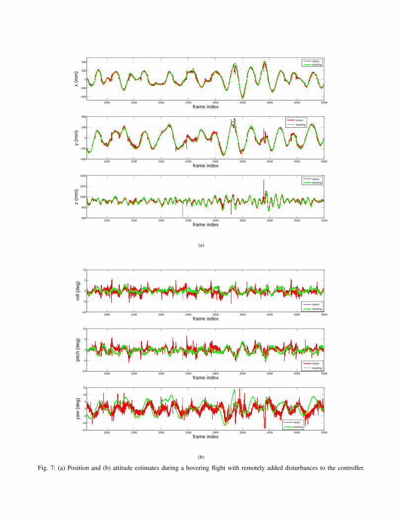
2) Hovering Case: Fig. 7 shows an autonomous hoveringflight with a set point of (0, 0, 1000)T (mm) for about 66seconds. More motion blur from the vibration of the quadro-tor is introduced in real flight, which will increase errors tothe pose estimates. We still manually added disturbances tothe control command to let the quadrotor hover in a largerarea, so that a relatively large range of perspectives couldbe tested in this case. Compared to the hand-held case, theperformance is not much worse and the RMS error is evensmaller. This is not surprising as in autonomous hoveringflight, the three Euler angles are normally very small, andthe quadrotor usually will not reach such poses where largedeviations may be introduced.
3) Autonomous Flight: A full trajectory of the quadrotorduring an autonomous taking off, hovering and landing flightis shown in Fig. 8. In this flight, it took the quadrotor about6 seconds to reach the set point for hovering state. After 5seconds of hovering around set point (0, 0, 1000)T (mm),it started the landing phase, which took about 3 seconds to

500 1000 1500 2000 2500 3000 3500 4000 4500 5000−400
−200
0
200
400
600
frame index
x (m
m)
visiontracking
500 1000 1500 2000 2500 3000 3500 4000 4500 5000−400
−200
0
200
400
frame index
y (m
m)
visiontracking
500 1000 1500 2000 2500 3000 3500 4000 4500 5000
200
400
600
800
1000
1200
1400
1600
frame index
z (m
m)
visiontracking
(a)
500 1000 1500 2000 2500 3000 3500 4000 4500 5000
−10
0
10
20
30
frame index
roll
(deg
)
visiontracking
500 1000 1500 2000 2500 3000 3500 4000 4500 5000
−20
−10
0
10
20
30
frame index
pitc
h (d
eg)
vision
tracking
500 1000 1500 2000 2500 3000 3500 4000 4500 5000
−40
−20
0
20
40
frame index
yaw
(de
g)
visiontracking
(b)
Fig. 6: (a) Position and (b) attitude estimates with hand-held quadrotor.
1000 1500 2000 2500 3000 3500 4000 4500 5000
−400
−200
0
200
400
frame index
x (m
m)
visiontracking
1000 1500 2000 2500 3000 3500 4000 4500 5000−400
−200
0
200
400
frame index
y (m
m)
vision
tracking
1000 1500 2000 2500 3000 3500 4000 4500 5000900
950
1000
1050
1100
frame index
z (m
m)
visiontracking
(a)
1000 1500 2000 2500 3000 3500 4000 4500 5000−10
−5
0
5
10
frame index
roll
(deg
)
vision
tracking
1000 1500 2000 2500 3000 3500 4000 4500 5000−10
−5
0
5
10
frame index
pitc
h (d
eg)
vision
tracking
1000 1500 2000 2500 3000 3500 4000 4500 5000−15
−10
−5
0
5
10
15
frame index
yaw
(de
g)
vision
tracking
(b)
Fig. 7: (a) Position and (b) attitude estimates during a hovering flight with remotely added disturbances to the controller.

500 600 700 800 900 1000 1100 1200 1300 1400 1500−100
−50
0
50
100
150
200
frame index
x (m
m)
vision
tracking
500 600 700 800 900 1000 1100 1200 1300 1400 1500−300
−200
−100
0
100
frame index
y (m
m)
vision
tracking
500 600 700 800 900 1000 1100 1200 1300 1400 1500
200
400
600
800
1000
frame index
z (m
m)
vision
tracking
(a)
500 600 700 800 900 1000 1100 1200 1300 1400 1500−5
0
5
frame index
roll
(deg
)
vision
tracking
500 600 700 800 900 1000 1100 1200 1300 1400 1500−10
−5
0
5
frame index
pitc
h (d
eg)
vision
tracking
500 600 700 800 900 1000 1100 1200 1300 1400 1500−10
−5
0
5
10
frame index
yaw
(de
g)
vision
tracking
(b)
Fig. 8: (a) Position and (b) attitude estimates during an autonomous takeoff, hovering and landing flight.

land on the landing pad. For the start of the takeoff phase,the quadrotor just ascends with open loop control until itobserves the circle in the landing pad. Based on ground truthdata of the final states of the quadrotor, the deviations of finallanding positions can be found. In our tests of 10 continuouslanding flights, the mean deviation of the position on XW , YWand yaw angle are about (24, 86)T (mm) and 6 degrees. Thedeviations are partially caused by the “blind” range of thecamera, which makes the landing not soft enough for themechanism of the quadrotor landing gear.
4) Computation Time: The computation time of our visionsystem during the flight in Fig. 8 is shown in Fig. 9. Themain part of it comes from the landing pad recognition phase,which has an average cost of less than 10 ms and a maximumof about 18 ms. Peaks in Fig. 9 may be mainly caused by theperformance of the onboard computer, as they did not occurwhen we tested video logfiles on an off-board PC. Whilehovering on the set point (0, 0, 1000)T (mm), the geometrycomputation time, including edge detection, ellipse fittingand the 6 DOF pose computation, is around 1 ms. Whenthe landing pad gets very close to the camera, its imageprojection may nearly occupy the whole image, which causesa longer time for geometry computation. When the quadrotorhovers above the landing pad at a height of about 300 mm,the geometry computation time reaches a maximum of about11 ms. The average time cost of the vision algorithm is lessthan 11 ms/frame, making full use of our 60 fps camera.
5) 5 DOF Accuracy Evaluation: We evaluate the 5 DOFRMSE of the quadrotor pose estimated by the onboard visionsystem at different distances to the landing pad and attitudes.The results are shown in Fig. 10. We manually fix thequadrotor above the landing pad and record the onboardestimates and ground truth data from the tracking systemat each pose for about 10 seconds, i.e. 600 frames, andcalculate the RMSEs of these measurements. Since roll andpitch angles have the same effect to pose estimation in ourgeometrical method, we set the pitch angle of the quadrotorto zero degrees and only change its roll angle. The yawangle is set to be about zero degree. The optical axis of thecamera nearly coincides with the ZB axis, with a small tilt inpitch angle. All onboard pose estimates for this evaluationare obtained within the same system configuration, whichmeans that the systematic deviation with respect to groundtruth data is constant throughout this experiment.
Fig. 10a demonstrates that the RMSE of the 3D positionestimates grows with increasing distance to the landing padand increasing roll angle. When the roll angle is nearly zero,the two possible solutions mentioned in Sect. IV-C.1 are veryclose to each other, which may cause our disambiguationmethod to fail and result in larger deviations. This canexplain why the RMSEs for roll = 0 may exceed those forroll = 10. Fig. 10b shows that there is no obvious relationshipbetween the attitude angle and its RMSE even if it increasesto up to 40 degrees, and its RMSE tends to grow with theincrease of the working distance. Attitude estimates of ourvision system are overall very accurate, with RMSEs below1.5 degrees for all tested poses. We do not expect our ground
truth data to be much more accurate than this, which couldexplain why the decrease in accuracy for higher distancesand angles in fig. 10b is not so obvious.
C. Outdoor Autonomous Flight
In our outdoor experiment, we locate the landing padon grass with some other objects beside it, like a smallpath, in cloudy and windless weather. In such scenario,the background of the landing pad is still textured, andthe assumption of the landing pad being parallel to theground plane in Sect. IV-C.2 is also not strictly satisfied.The autonomous flight achieved similar overall performanceas in the previous indoor scenario. Fig. 11 shows the positionestimation of the onboard vision system during a successfultakeoff, hovering and landing outdoor flight.
VII. CONCLUSIONS
We have presented an onboard vision system that candetect a landing pad consisting of the letter “H” surroundedby a circle, from images captured by a monocular camera ona MAV and determine the 6 DOF pose of the MAV relativeto the landing pad using projective geometry.
Our algorithms are computationally efficient enough toprocess up to 60 frames per second on our onboard computer.We have shown that the whole system produces robust andaccurate pose estimates, which were evaluated using anexternal tracking system. We used these pose estimates toenable a completely autonomous helicopter to reliably startfrom, hover above, and land on the landing pad, even if thisis located within a challenging environment, i.e. in front ofa visually cluttered background.
A video demonstrating our autonomous quadrotor flyingusing this vision system can be found online2.
In future work, we plan to use the prestented vision systemat the beginning and at the end of autonomous flights of ourMAVs. We also want to use the pose estimates produced bythis system to initialize the otherwise unknown scale factorof a monocular visual SLAM system. It may be interesting toinvestigate whether sensor fusion of both attitude estimatesprovided by the IMU and our vision system can furtherimprove the attitude-estimation accuracy.
VIII. ACKNOWLEDGMENTS
The authors would like to thank the Pixhawk team at ETHZurich for the release of the open source Pixhawk quadrotorplatform, and Prof. Andreas Schilling from the computergraphics group in our faculty for providing us with the accessto the tracking system. We would also like to thank Karl E.Wenzel in our group for the discussions about this paper.
References
[1] J.Y. Bouguet, ”Camera Calibration Toolbox for Matlab”,http://www.vision.caltech.edu/bouguetj/calib doc, 2001.
[2] J. Canny, ”A computational approach to edge detection”, IEEE Trans-actions on Pattern analysis and Machine Intelligence, Vol. 8(6), 1986,pp. 679-698.
2http://www.youtube.com/watch?v=yvyzvttuNsQ

500 600 700 800 900 1000 1100 1200 1300 1400 1500
0
5
10
15
20
frame index
com
puta
tion
time
(ms)
RecognitionGeometry
500 600 700 800 900 1000 1100 1200 1300 1400 15005
10
15
20
25
30
frame index
tota
l tim
e (m
s)
Fig. 9: Computation time during the autonomous takeoff, hovering, and landing flight.
(a) (b)
Fig. 10: (a) 3D Position RMSE and (b) attitude RMSE within different distances and attitudes to the landing pad.
[3] A. Cesetti, E. Frontoni, A. Mancini, P. Zingaretti, S. Longhi, ”AVision-Based Guidance System for UAV Navigation and Safe Landingusing Natural Landmarks”, Journal of Intelligent & Robotic Systems,Vol. 57, No. 1-4, 2010, pp. 233-257.
[4] Q. Chen, H. Wu, T. Wada, ”Camera Calibration with Two ArbitraryCoplanar Circles”, ECCV-2004, LNCS, Vol. 3023/2004, 2004, pp. 521-532.
[5] Z. Chen, and J. B. Huang, ”A vision-based method for the circlepose determination with a direct geometric interpretation”, IEEETransactions on Robotics and Automation, Vol. 15(6), 1999, pp. 1135-1140.
[6] J. Diebel, ”Representing attitude: Euler angles, unit quaternions, androtation vectors”, Technical report, Stanford University, Stanford,California 94301-9010, October 2006.
[7] D. Eberli, D. Scaramuzza, S. Weiss, R. Siegwart, ”Vision BasedPosition Control for MAVs Using One Single Circular Landmark”,Journal of Intelligent & Robotic Systems, Vol. 61, No. 1-4, 2011, pp.495-512.
[8] O. Faugeras, Three-Dimensional Computer Vision: a Geometric View-point, MIT Press, 1993.
[9] Fitzgibbon, A., Pilu, M., Fisher, R.B., ”Direct least square fittingof ellipses”, IEEE Transaction on Pattern Analysis and MachineIntelligence, Vol. 21(5), 1999, pp. 476-480.
[10] D. Forsyth, J.L. Mundy, A. Zisserman, C. Coelho, A. Heller, C.Rothwell, ”Invariant descriptors for 3D object recognition and pose”,IEEE Transactions on Pattern Analysis and Machine Intelligence, Vol.13(10), 1991, pp. 971-991.
[11] P.J. GarciaPardo, G.S. Sukhatme, J.F. Montgomery, ”Towards vision-based safe landing for an autonomous helicopter”, Robotics andAutonomous Systems, Vol. 38(1), 2002, pp. 19-29.
[12] L. He, Y. Chao, and K. Suzuki, ”A run-based two-scan labelingalgorithm”, IEEE Transactions on Image Processing, Vol. 17(5), May2008, pp. 749-756.
[13] K.Kanatani and L.Wu, ”3D Interpretation of Conics and Orthogonal-ity”, Image Understanding, Vol. 58, 1993, pp. 286-301.
[14] S. Lange, N. Sunderhauf, P. Protzel, ”A Vision Based Onboard Ap-proach for Landing and Position Control of an Autonomous MultirotorUAV in GPS-Denied Environments”, Proceedings 2009 InternationalConference on Advanced Robotics, Munich, June 2009, pp. 1-6.
[15] L. Meier, P. Tanskanen, F. Fraundorfer, M. Pollefeys, ”PIXHAWK:A system for autonomous flight using onboard computer vision”,Proceedings 2011 IEEE International Conference on Robotics andAutomation, Shanghai, May 2011, pp. 2992-2997.
[16] D. Mellinger, N. Michael, V. Kumar, ”Trajectory generation andcontrol for precise aggressive maneuvers with quadrotors”, The In-ternational Journal of Robotics Research, Jan. 2012 online first,

800 1000 1200 1400 1600 1800
−200
−100
0
100
200
frame index
x (m
m)
800 1000 1200 1400 1600 1800−400
−200
0
200
400
frame index
y (m
m)
800 1000 1200 1400 1600 1800
400
600
800
1000
1200
frame index
z (m
m)
Fig. 11: Position estimates during an outdoor autonomous takeoff, hovering and landing flight.
doi:10.1177/0278364911434236.[17] T. Merz, S. Duranti, G. Conte, ”Autonomous landing of an unmanned
helicopter based on vision and inertial sensing”, Experimental RoboticsIX, STAR, Vol. 21, 2006, pp. 343-352.
[18] N. Michael, D. Mellinger, Q. Lindsey, V. Kumar, ”The GRASPMultiple Micro UAV Testbed”, Robotics and Automation Magazine,Vol. 17(3), 2010, pp. 56-65.
[19] G. Bradski, ”The OpenCV Library”, Dr. Dobb’s Journal of SoftwareTools, 2000.
[20] S. Saripalli, J.F. Montgomery, G.S. Sukhatme, ”Visually guided land-ing of an unmanned aerial vehicle ”, IEEE Transactions on Roboticsand Automation, Vol. 19(3), 2003, pp. 371-380.
[21] S.A. Scherer, D. Dube, P. Komma, A. Masselli, A. Zell, ”RobustReal-Time Number Sign Detection on a Mobile Outdoor Robot”,In Proceedings of the 6th European Conference on Mobile Robots(ECMR 2011), Orebro, Sweden, September 2011.
[22] K. E. Wenzel, P. Rosset, A. Zell., ”Low-Cost Visual Tracking of aLanding Place and Hovering Flight Control with a Microcontroller”,Journal of Intelligent & Robotic Systems, 2009, Vol. 57(1-4), pp. 297-311.
[23] K. E. Wenzel, A. Masselli, A. Zell, ”Automatic Take Off, Tracking andLanding of a Miniature UAV on a Moving Carrier Vehicle”, Journalof Intelligent & Robotic Systems, Vol. 61, 2011, pp. 221-238.
[24] G. Xu, Y. Zhang, S. Ji, Y. Cheng, Y. Tian, ”Research on computervision-based for UAV autonomous landing on a ship”, Pattern Recog-nition Letters, Vol. 30(6), 2009, pp. 600-605.
[25] A. Zell, N. Mache, R. Hubner, G. Mamier, M. Vogt, M. Schmalzl,and K.-U. Herrmann, ”SNNS (stuttgart neural network simulator)”,In Josef Skrzypek, editor, Neural Network Simulation Environments,volume 254 of The Springer International Series in Engineering andComputer Science, Kluwer Academic Publishers, Norwell, MA, USA,February 1994. Chapter 9.
[26] Z. Zhang, ”A Flexible New Technique for Camera Calibration”, IEEETransaction on Pattern Analysis and Machine Intelligence, Vol. 22(11),Nov. 2000, pp. 1330-1334.