An objective study of beha vior of permanent magnet ...
8
See discussions, stats, and author profiles for this publication at: https://www.researchgate.net/publication/327450084 An objective study of behavior of permanent magnet synchronous motor under abnormal conditions Article in International Journal of Engineering and Technology · September 2018 DOI: 10.14419/ijet.v7i4.15550 CITATIONS 0 READS 214 5 authors, including: Zaid H. Al-Tameemi Al-Furat Al-Awsat Technical University 11 PUBLICATIONS 5 CITATIONS SEE PROFILE Dalya H. Al-mamoori Al-Furat Al-Awsat Technical University 7 PUBLICATIONS 0 CITATIONS SEE PROFILE All content following this page was uploaded by Zaid H. Al-Tameemi on 05 September 2018. The user has requested enhancement of the downloaded file.
Transcript of An objective study of beha vior of permanent magnet ...

See discussions, stats, and author profiles for this publication at: https://www.researchgate.net/publication/327450084
An objective study of behavior of permanent magnet synchronous motor
under abnormal conditions
Article in International Journal of Engineering and Technology · September 2018
DOI: 10.14419/ijet.v7i4.15550
CITATIONS
0READS
214
5 authors, including:
Zaid H. Al-Tameemi
Al-Furat Al-Awsat Technical University
11 PUBLICATIONS 5 CITATIONS
SEE PROFILE
Dalya H. Al-mamoori
Al-Furat Al-Awsat Technical University
7 PUBLICATIONS 0 CITATIONS
SEE PROFILE
All content following this page was uploaded by Zaid H. Al-Tameemi on 05 September 2018.
The user has requested enhancement of the downloaded file.

Copyright © 2018 Zaid H. Al-Tameemi et al. This is an open access article distributed under the Creative Commons Attribution License, which
permits unrestricted use, distribution, and reproduction in any medium, provided the original work is properly cited.
International Journal of Engineering & Technology, 7 (4) (2018) 1970-1976
International Journal of Engineering & Technology
Website: www.sciencepubco.com/index.php/IJET doi: 10.14419/ijet.v7i4.15550
Research paper
An objective study of behavior of permanent magnet
synchronous motor under abnormal conditions
Zaid H. Al-Tameemi 1 *, Hayder H. Enawi 2, Karrar M. Al-Anbary 3,
Dalya H. Al-Mamoori 1, Hussam M. Almukhtar 4
1 Technical College /Al-Mussaib, Al-Furat Al-Awsat Technical University, Iraq
2 Engineering College, Babylon University, Iraq 3 Biomedical department, Warith Al-Anbiyaa University,Iraq
4 Middle Refineries, Najaf Refinery, Ministry of Oil, Iraq
*Corresponding author E-mail: [email protected]
Abstract
Permanent magnet synchronous motors (PMSM) can be used directly in place of the induction motors (I.M) for several industrial appli-
cations since it is characterized by high efficiency, high power factor, and high power compared to I.M. However, this type of motor
suffers from some abnormal conditions that result in minimizing power quality such as voltage sags, temporary disturbances, and faults
within the network. In this paper, the behavior of PMSM has been studied under the above conditions in a Matlab/Simulink environment.
It was noticed that such problems caused an increase in the amount of torque and current in this motor which impacted negatively on the
motor speed and influenced the behavior of PMSM.
Keywords: PMSM; Short Interruptions; Faults; Broken Rotor Bar.
1. Introduction
In the last few years, permanent magnet synchronous mo-
tors(PMSM) have gained a considerable attention in the industries
and academic world [1]. Practically, PMSMs are considered more
desirable than induction motors (IM) with respect to high duty
factor industrial applications such as pump, fan, and compressor
because of its high efficiency, subordinate life cycle, high power
factor, and less sensitivity to supply frequency and voltage devia-
tions [2,3]. It is worth mentioning that its use is increasing because
of the decreasing cost of commercial magnets. The excitation of
PMSM can be supplied partially by using the magnets that are
placed in the rotor and could be obtained partly by using the line
current. A squirrel cage is supplied to hasten PMSM from a
standstill when begun ‘across the line’ [4]. During the last three
decades, many researches have been implemented in order to test
PMSM for eco-technique feasibility and stability in both transient
and steady states. Conversely, the researches carried out on the
reliability of PMSM in the reallife scenarios (subjection to high
power quality challenges) are limited [5]. Currently, power quality
is a major concern in the electrical power utility field because of
modern equipment and other motors which are sensitive to chang-
es in frequency and voltage. Voltage sags, harmonics, and short
disturbances are the major problems related to power quality that
impact on motor performance. It should be clear that more than
80% of the power quality- related issues are concerned with the
occurrence of short interruptions [6]. The previous studies focused
only on the analysis of I.M under abnormal conditions and ignored
PMSM performance. Therefore, this paper will shed light on the
behavior of PMSM under short-time disturbances and faults. A
Matlab/Simulink environment was used to conduct this study.
2. Short interruptions
A short interruption can be defined as the whole loss of voltage
whether on single phase or more for certain periods ranging from
0.5 to 3 cycles [6]. A momentary disturbance always has the same
cause as long disturbances, such as an inappropriate protection
intervention and a fault in clearing the protection. When a source
is relinked automatically within 1 minute, the produced case is
called a short disturbance ; however, a manual restoration of the
supply leads to long interruptions. Automatic reconnections can be
implemented by closing the circuit breaker that cleared the result-
ing fault [7]. These interruptions have a significant impact on
PMSM which is designed to function in normal conditions such as
a balanced sinusoidal, periodic, steady-state voltage which can
cause huge current and torque transients.
2.1. Occurrence of voltage interruption
PMSM is designed to operate on sinusoidal, periodic, steady-state
voltages. Short disturbances can increase the amount of torque and
current in this motor. When PMSM is disconnected from the
source, the current in the stator circuit halts and flow into the
PMSM. This, in turn, contributes to the deceleration of the rotor.
Once there is a supply disturbance, the PMSM is misplaced direct-
ly; then, the rotating magnetic field produced by the stator current
disappears. On the other hand, the rotating magnetic field generat-
ed by the magnets is maintained on the decelerating rotor.

International Journal of Engineering & Technology 1971
3. Effect of broken rotor bar on PMSM
In the last two decades, many researchers studied some of the
faults that occur in machines, including broken rotor bar faults.
Since 1980, several studies have been carried out in the field of
broken rotor detection. Douglas (2003)studied this type of fault in
the rotor using FFT method and Discrete Wavelet Transformer in
a transient state by changing the load [8]. A discrete pack trans-
former has been reportedly used to detect broken rotor bar faults
[8].It is worth mentioning that rotor failures account for about
10% of total faults that occur in machines[9]. In this regard, many
reasons can contribute to damaging rotor bars, such as thermal
stress,mmanufacturing defects, magnetic and mechanical stresses.
4. Impact of fault on PMSM
This type of fault is deemed as a power-related electrical problem
which leads to the loss of one or more phases that supply a motor
[10]. This situation impacts negatively on the behavior of motors,
as demonstrated in Case3.
5. Impact of fault on PMSM within grid
Power quality is considered as an essential branch of electric power
engineering. It plays a significant role in delivering quality power
for industrial use. Many problems can contribute to decreasing the
power quality in a system, such as voltage sag caused by some
faults during specific periods, thereby, costing several millions of
dollars [11]. Therefore, this section sheds light on some system
problems in the presence of PMSM during faults.
6. Simulation results
To understand the impact of the aforementioned faults, different
cases have been considered. The motor data are given as shown in
each case.
Case1: short interruption
A PMSM with specific parameters given in Table 1 is simulated in
a Matlab/Simpower system.
Table 1: Motor Parameters
Voltage in volt 220 Flux linkage 0.1852
Frequency in Hz 50 No. poles 8 Stator resistance (ohm) 1.6
Armature inductance (H) 0.000395
Fig. 1: PMSM Under Short Interruptions.
A three-phase supply is disconnected at 0.2 seconds once the
PMSM reached a steady state. The behavior of PMSM is evaluat-
ed under different cycle interruptions (2 - 6 cycles) as shown in
the figures below. The speed is observed to greatly reduce because
of the 2,4,6, and 8 interruption cycles carried out in the supply. A
synchronism of the motor is achieved after 0.04 to 0.16 seconds
which is less than the starting time of the motor .Figures2, 3, and 4
showed the stator currents falling to zero after all the interruptions.
Fig. 2: Speed, Torque and Stator Current at 2 Cycle Interruption.
Fig. 3: Speed, Torque and Stator Current at 4 Cycle Interruption.
Fig. 4: Speed, Torque and Stator Current at 6 Cycle Interruption.
Case2: Broken Rotor Fault

1972 International Journal of Engineering & Technology
The dynamics of a sudden torque change on the PMSM is consid-
ered. The PMSM is connected to three-phase sources with a small
resistive load integrated into the network. This motor is initiated
with a load of 1 p.u. When the motor has reached a steady state
condition, the torque was suddenly increased from 1 to 20 at 1
second. This increment led to an accelerated torque and a decreas-
ing motor speed as shown in Figure 7.
Fig. 5: PMSM Under Sudden Change in Torque.
Fig. 6: PMSM Under Normal Torque.
Fig. 7: PMSM Under Sudden Change in Torque.
Case3: Impact of fault on PMSM
PMSM model are created in a Matlab environment as shown in
Figure 8. This mode is utilised to comprehend the impact of a
three phase fault on the performance of PMSM, including torque
and speed. The Simulink model comprises of 100(peak) and 50 Hz
3-phase source and three levels inverter. Two scopes are placed in
the system to monitor the torque and speed under different load
conditions in the presence of a three-phase fault. The fault is ap-
plied during 0.01 to 0.1s.
Fig. 8: PMSM Under Fault Condition.
Fig. 9: Torque and Speed Under No.Load Condition.
Fig. 10: Torque and Speed Under Constant Load Condition.

Copyright © 2018 Zaid H. Al-Tameemi et al. This is an open access article distributed under the Creative Commons Attribution License, which
permits unrestricted use, distribution, and reproduction in any medium, provided the original work is properly cited.
Fig. 11: Torque and Speed Under Variable Load Condition.
Case4: Impact Of Fault On PMSM Within Grid
Different scenarios are performed to understand the influence of faults on PMSMs that run within power networks, as demonstrated be-
low.
a) Normal condition
The PMSM used here consists of 30 MVA, 11 KV, and a 50 Hz 3-phase source. The feeder has a transformer of 11/0.4 KV, 1MVA del-
ta/star. Two scopes were situated at 0.4 and 11 KV bus to monitor the voltage waveforms and other waveforms including the rotor speed,
rotor theta, and stator current under various situations. In this case, the model runs under a normal case
Fig. 12: PMSM under Fault within Grid.

Copyright © 2018 Zaid H. Al-Tameemi et al. This is an open access article distributed under the Creative Commons Attribution License, which
permits unrestricted use, distribution, and reproduction in any medium, provided the original work is properly cited.
Fig. 13: PMSM under Normal Condition within Grid
.
Fig. 14: Voltage Sag at RMS Scope.
Fig. 15: Speed and Torque under Normal Condition.
b) Three phase fault
A line fault mode is created in a Matlab environment as shown in
Figure 12. This mode is used to simulate a voltage sag due to line
faults. The Simulink model comprised of a 30 MVA, 11 KV, 50
Hz 3-phase source block feeding through 11/0.4 KV, 1MVA del-
ta/star transformer with 10 kW resistive load in the line between
the motor and a 0.4 KV bus. Two scopes were placed at 0.4 and
11 KV buses to monitor the voltage waveforms and other wave-
forms, including rotor speed, rotor theta, and stator current in the
presence of a three-phase fault. The fault block was placed at 11
KV bus to simulate a three-phase fault. In this part, the perfor-
mance of PMSM was investigated by applying a three-phase fault
as shown in the figures below. Figures 17 and 18 show voltage sag
waveforms resulting from a three-phase fault at 11 KV feeder
during the period of 0.15-0.25 s. It is noted that the 11 kV bus
faces big voltage sags at all phases because of the low fault re-
sistance between the three faulted lines as shown in the figures
below:
Fig. 16: Voltage Sag Caused by Three Phase Fault at 11 Bus Line.
Fig. 17: Voltage Sag at RMS Scope.
It can be noted that voltage sag impacts negatively on the rotor
speed, rotor angle theta, and stator current. Most of the values
witnessed reductions and vibrations during this period while the
stator current –q faces swelling as shown in the figure below.

International Journal of Engineering & Technology 1975
Fig. 18: Speed, and Torque under Three Phase Fault.
c) Line to line fault
In this section, the performance of PMSM is investigated by ap-
plying an L-L fault as shown in the figures below. Figures 19 and
20 show voltage sag waveforms caused by L-L faults that oc-
curred at 11 kV feeder during the period of 0.15-0.3 s. It is noted
that the 11 bus faces two voltage sags at different voltage magni-
tudes because of the high fault resistance (8 ohms) between the
two faulted lines as shown in figure 20. The faulted phase at 0.4
KV bus faces a small voltage swell because there is no ground
point in this type of fault, as well as the high fault resistance.
Fig. 19: Voltage Sag Caused by L-L Fault at 11 Bus Line.
In this study, voltage sag waveforms are presented in RMS scope.
It represents the analysis of an L-L fault voltage sag waveform in
the figure above. The voltage sag magnitudes for each phase are
visualized. Small oscillations are observed to arise at the pre-sag
and post-sag, as well as swells because of a phase shift during the
fault [12].
Fig. 20: Voltage Sag at RMS Scope.
Fig. 21: Speed and Torque under L-L Fault Line to Ground Fault.
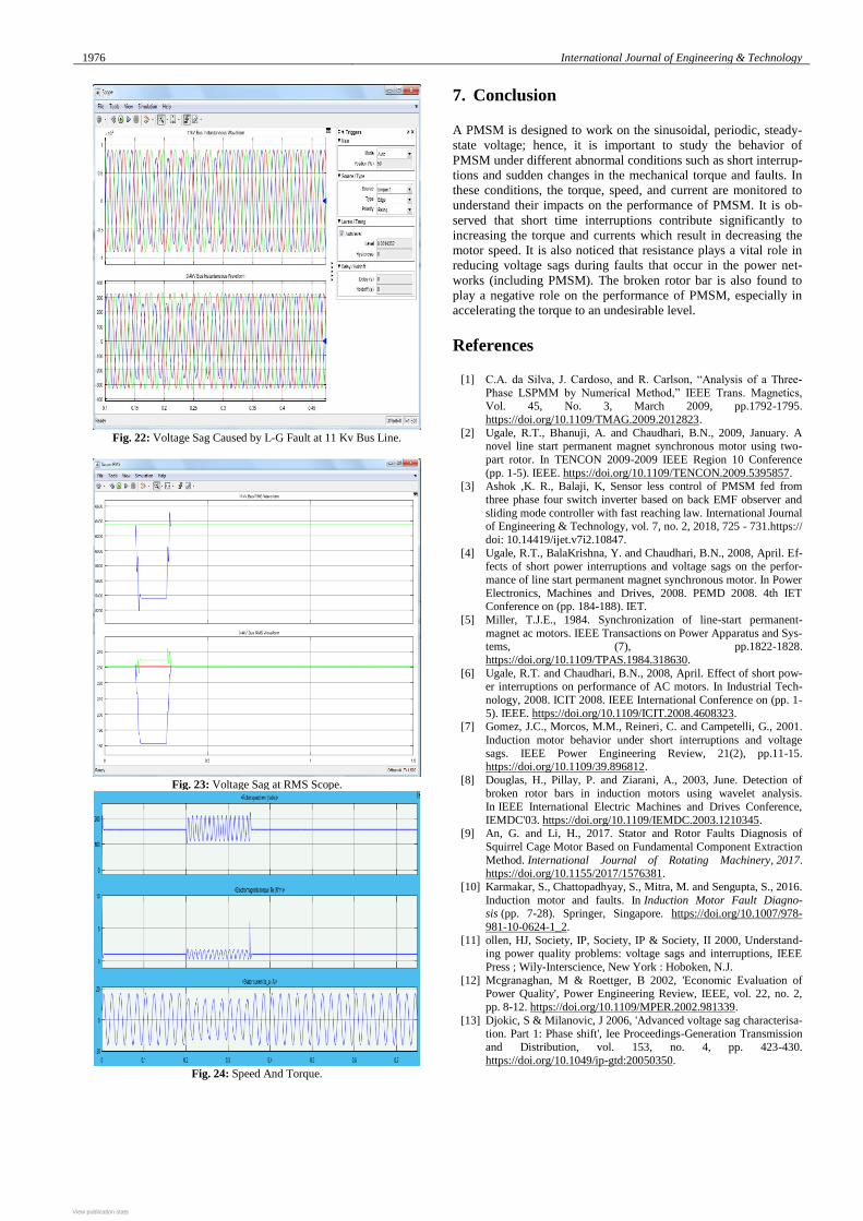
d) Line to ground fault
In this section, the performance of PMSM is investigated by apply-
ing an L-G fault as shown in the figures below. Figures 22 and 23
show voltage sag waveforms caused by an L-G fault at an 11 kV
feeder during the period of 0.15-0.3 s. It was noted that the 11 bus
faced small voltage sags at the faulted line because of the high fault
resistance (8 ohms) between the faulted line and the ground point.
The phases at 0.4 KV bus also faced a small voltage swell and sag
because of the presence of a ground point and a high fault re-
sistance in this type of fault [13].
1976 International Journal of Engineering & Technology
Fig. 22: Voltage Sag Caused by L-G Fault at 11 Kv Bus Line.
Fig. 23: Voltage Sag at RMS Scope.
Fig. 24: Speed And Torque.
7. Conclusion
A PMSM is designed to work on the sinusoidal, periodic, steady-
state voltage; hence, it is important to study the behavior of
PMSM under different abnormal conditions such as short interrup-
tions and sudden changes in the mechanical torque and faults. In
these conditions, the torque, speed, and current are monitored to
understand their impacts on the performance of PMSM. It is ob-
served that short time interruptions contribute significantly to
increasing the torque and currents which result in decreasing the
motor speed. It is also noticed that resistance plays a vital role in
reducing voltage sags during faults that occur in the power net-
works (including PMSM). The broken rotor bar is also found to
play a negative role on the performance of PMSM, especially in
accelerating the torque to an undesirable level.
References
[1] C.A. da Silva, J. Cardoso, and R. Carlson, “Analysis of a Three-
Phase LSPMM by Numerical Method,” IEEE Trans. Magnetics, Vol. 45, No. 3, March 2009, pp.1792-1795.
https://doi.org/10.1109/TMAG.2009.2012823.
[2] Ugale, R.T., Bhanuji, A. and Chaudhari, B.N., 2009, January. A novel line start permanent magnet synchronous motor using two-
part rotor. In TENCON 2009-2009 IEEE Region 10 Conference
(pp. 1-5). IEEE. https://doi.org/10.1109/TENCON.2009.5395857. [3] Ashok ,K. R., Balaji, K, Sensor less control of PMSM fed from
three phase four switch inverter based on back EMF observer and
sliding mode controller with fast reaching law. International Journal of Engineering & Technology, vol. 7, no. 2, 2018, 725 - 731.https://
doi: 10.14419/ijet.v7i2.10847.
[4] Ugale, R.T., BalaKrishna, Y. and Chaudhari, B.N., 2008, April. Ef-
fects of short power interruptions and voltage sags on the perfor-
mance of line start permanent magnet synchronous motor. In Power
Electronics, Machines and Drives, 2008. PEMD 2008. 4th IET Conference on (pp. 184-188). IET.
[5] Miller, T.J.E., 1984. Synchronization of line-start permanent-
magnet ac motors. IEEE Transactions on Power Apparatus and Sys-tems, (7), pp.1822-1828.
https://doi.org/10.1109/TPAS.1984.318630.
[6] Ugale, R.T. and Chaudhari, B.N., 2008, April. Effect of short pow-er interruptions on performance of AC motors. In Industrial Tech-
nology, 2008. ICIT 2008. IEEE International Conference on (pp. 1-
5). IEEE. https://doi.org/10.1109/ICIT.2008.4608323. [7] Gomez, J.C., Morcos, M.M., Reineri, C. and Campetelli, G., 2001.
Induction motor behavior under short interruptions and voltage
sags. IEEE Power Engineering Review, 21(2), pp.11-15. https://doi.org/10.1109/39.896812.
[8] Douglas, H., Pillay, P. and Ziarani, A., 2003, June. Detection of
broken rotor bars in induction motors using wavelet analysis.
In IEEE International Electric Machines and Drives Conference,
IEMDC'03. https://doi.org/10.1109/IEMDC.2003.1210345. [9] An, G. and Li, H., 2017. Stator and Rotor Faults Diagnosis of
Squirrel Cage Motor Based on Fundamental Component Extraction
Method. International Journal of Rotating Machinery, 2017. https://doi.org/10.1155/2017/1576381.
[10] Karmakar, S., Chattopadhyay, S., Mitra, M. and Sengupta, S., 2016.
Induction motor and faults. In Induction Motor Fault Diagno-sis (pp. 7-28). Springer, Singapore. https://doi.org/10.1007/978-
981-10-0624-1_2.
[11] ollen, HJ, Society, IP, Society, IP & Society, II 2000, Understand-ing power quality problems: voltage sags and interruptions, IEEE
Press ; Wily-Interscience, New York : Hoboken, N.J.
[12] Mcgranaghan, M & Roettger, B 2002, 'Economic Evaluation of Power Quality', Power Engineering Review, IEEE, vol. 22, no. 2,
pp. 8-12. https://doi.org/10.1109/MPER.2002.981339.
[13] Djokic, S & Milanovic, J 2006, 'Advanced voltage sag characterisa-tion. Part 1: Phase shift', Iee Proceedings-Generation Transmission
and Distribution, vol. 153, no. 4, pp. 423-430.
https://doi.org/10.1049/ip-gtd:20050350.
View publication statsView publication stats


![wk13 alg 2nd.notebookmrscolelovesmath.weebly.com/.../19_04_10_2nd.pdf · ] *yr-value of the vertex Extrema: maximum at the vertex End Beha vior. As f(x) + —cn As f(x) + —cn Interval](https://static.fdocuments.net/doc/165x107/607a7c18f11ee745e1268e06/wk13-alg-2ndnote-yr-value-of-the-vertex-extrema-maximum-at-the-vertex-end-beha.jpg)