An Object-Oriented Framework for Experimenting with Alternative
166
UNIVERSITY OF CALIFORNIA Irvine An Object-Oriented Framework for Experimenting with Alternative Process Architectures for Parallelizing Communication Subsystems A dissertation submitted in partial satisfaction of the requirements for the degree Doctor of Philosophy in Information and Computer Science by Douglas Craig Schmidt Committee in charge: Professor Tatsuya Suda, Chair Professor Richard W. Selby, Co-Chair Professor George Polyzos 1995
Transcript of An Object-Oriented Framework for Experimenting with Alternative

UNIVERSITY OF CALIFORNIA
Irvine
An Object-Oriented Framework for Experimenting withAlternative Process Architectures for Parallelizing
Communication Subsystems
A dissertation submitted in partial satisfaction of the
requirements for the degree Doctor of Philosophy
in Information and Computer Science
by
Douglas Craig Schmidt
Committee in charge:
Professor Tatsuya Suda, Chair
Professor Richard W. Selby, Co-Chair
Professor George Polyzos
1995

c 1995
DOUGLAS CRAIG SCHMIDT
ALL RIGHTS RESERVED

The dissertation of Douglas C. Schmidt is approved,
and is acceptable in quality and form for
publication on microfilm:
Committee Chair
University of California, Irvine
1995
ii

Dedication
This dissertation is dedicated to the memory of Terry Williams (1971–1991). Terry wasmy friend and weight-lifting partner, who was killed in a tragic airplane accident in
February, 1991. In the words of Marcus Antonius from Shakespeare’sJulius Caesar:
“His life was gentle, and the elements soMixed in him that nature might stand up
And say to all the world: this was a man.”
iii
Contents
Dedication : : : : : : : : : : : : : : : : : : : : : : : : : : : : : : : : : : : : : iii
List of Figures : : : : : : : : : : : : : : : : : : : : : : : : : : : : : : : : : : v
List of Tables : : : : : : : : : : : : : : : : : : : : : : : : : : : : : : : : : : : vii
Acknowledgements: : : : : : : : : : : : : : : : : : : : : : : : : : : : : : : : viii
Curriculum Vitae : : : : : : : : : : : : : : : : : : : : : : : : : : : : : : : : : x
Abstract : : : : : : : : : : : : : : : : : : : : : : : : : : : : : : : : : : : : : : xvi
Chapter 1 Introduction : : : : : : : : : : : : : : : : : : : : : : : : : : : : 1
Chapter 2 A Survey of Software Components in Communication SubsystemArchitectures : : : : : : : : : : : : : : : : : : : : : : : : : : : : : : : : : : : 5
2.1 Introduction : : : : : : : : : : : : : : : : : : : : : : : : : : : : : : : 52.2 Levels of Abstraction in a Communication Subsystem Architecture: : : 82.3 A Taxonomy of Communication Subsystem Architecture Mechanisms: 142.4 Survey of Existing OS Communication Subsystem Architectures: : : : 392.5 Summary: : : : : : : : : : : : : : : : : : : : : : : : : : : : : : : : : 60
Chapter 3 The ADAPTIVE Service eXecutive Framework : : : : : : : : : 623.1 Introduction : : : : : : : : : : : : : : : : : : : : : : : : : : : : : : : 623.2 Object-Oriented Frameworks: : : : : : : : : : : : : : : : : : : : : : 633.3 The Object-Oriented Architectures of theASXFramework : : : : : : : 653.4 Summary: : : : : : : : : : : : : : : : : : : : : : : : : : : : : : : : : 98
Chapter 4 Communication Subsystem Performance Experiments: : : : : 994.1 Introduction : : : : : : : : : : : : : : : : : : : : : : : : : : : : : : : 994.2 Related Work : : : : : : : : : : : : : : : : : : : : : : : : : : : : : : 1004.3 Multi-processor Platform : : : : : : : : : : : : : : : : : : : : : : : : 1014.4 Functionality of the Communication Protocol Stacks: : : : : : : : : : 1034.5 Structure of the Process Architectures: : : : : : : : : : : : : : : : : : 1054.6 Measurement Results: : : : : : : : : : : : : : : : : : : : : : : : : : 1104.7 Summary: : : : : : : : : : : : : : : : : : : : : : : : : : : : : : : : : 126
Chapter 5 Conclusions and Future Research Problems: : : : : : : : : : : 132
iv

List of Figures
2.1 Protocol Graph for Internet and OSI Communication Models: : : : : : 92.2 Architectural Components in a Communication Subsystem: : : : : : : 102.3 Process Architecture Components and Interrelationships: : : : : : : : 182.4 Task-based Process Architectures: : : : : : : : : : : : : : : : : : : : 192.5 Message-based Process Architectures: : : : : : : : : : : : : : : : : : 232.6 External and Internal Factors Influencing Process Architecture Perfor-
mance : : : : : : : : : : : : : : : : : : : : : : : : : : : : : : : : : : 242.7 Layered and De-layered Multiplexing and Demultiplexing: : : : : : : 342.8 System V STREAMS Architecture: : : : : : : : : : : : : : : : : : : 41
3.1 Class Libraries vs. Frameworks: : : : : : : : : : : : : : : : : : : : : 643.2 Class Categories in theASXFramework: : : : : : : : : : : : : : : : : 653.3 Components in theStream Class Category : : : : : : : : : : : : : : 683.4 Alternative Methods for Invokingput andsvc Methods: : : : : : : : 743.5 Components in theReactor Class Category: : : : : : : : : : : : : : 763.6 Components in theService Configurator Class Category: : : : 783.7 EBNF Format for a Service Config Entry: : : : : : : : : : : : : : : : 833.8 State Transition Diagram for Service Configuration, Execution, and Re-
configuration: : : : : : : : : : : : : : : : : : : : : : : : : : : : : : : 853.9 IPC SAPClass Category Relationships: : : : : : : : : : : : : : : : : 913.10 TheSOCKSAPInheritance Hierarchy: : : : : : : : : : : : : : : : : : 93
4.1 Connectional Parallelism Process Architecture: : : : : : : : : : : : : 1064.2 Message Parallelism Process Architecture: : : : : : : : : : : : : : : : 1074.3 Layer Parallelism Process Architecture: : : : : : : : : : : : : : : : : 1094.4 Connection-oriented Connectional Parallelism Throughput: : : : : : : 1124.5 Connection-oriented Message Parallelism Throughput: : : : : : : : : 1134.6 Connection-oriented Layer Parallelism Throughput: : : : : : : : : : : 1144.7 Relative Speedup for Connection-oriented Connectional Parallelism: : 1154.8 Relative Speedup for Connection-oriented Message Parallelism: : : : : 1164.9 Relative Speedup for Connection-oriented Layer Parallelism: : : : : : 1174.10 Comparison of Connectional Parallelism and Message Parallelism: : : 1184.11 Connectionless Message Parallelism Throughput: : : : : : : : : : : : 1194.12 Connectionless Layer Parallelism Throughput: : : : : : : : : : : : : : 1204.13 Relative Speedup for Connectionless Message Parallelism: : : : : : : 121
v
4.14 Relative Speedup of Connectionless Layer Parallelism: : : : : : : : : 1224.15 Connection-oriented Connectional Parallelism Context Switching: : : 1234.16 Connection-oriented Message Parallelism Context Switching: : : : : : 1244.17 Connectionless Message Parallelism Context Switching: : : : : : : : : 1254.18 Connection-oriented Layer Parallelism Context Switching: : : : : : : 1264.19 Connectionless Layer Parallelism Context Switching: : : : : : : : : : 1274.20 Connection-oriented Connectional Parallelism Synchronization Overhead1284.21 Connection-oriented Message Parallelism Synchronization Overhead: : 1294.22 Connection-oriented Layer Parallelism Synchronization Overhead: : : 1304.23 Connectionless Message Parallelism Synchronization Overhead: : : : 1304.24 Connectionless Layer Parallelism Synchronization Overhead: : : : : : 131
vi

List of Tables
2.1 Communication Subsystem Taxonomy Template: : : : : : : : : : : : 152.2 STREAMS Profile: : : : : : : : : : : : : : : : : : : : : : : : : : : : 402.3 BSD UNIX Profile: : : : : : : : : : : : : : : : : : : : : : : : : : : : 452.4 x-kernel Profile: : : : : : : : : : : : : : : : : : : : : : : : : : : : : : 492.5 Conduit Profile: : : : : : : : : : : : : : : : : : : : : : : : : : : : : : 52
vii

Acknowledgements
I would like to express my gratitude to my advisor, Professor Tatsuya Suda, for hisguidance and support during my Ph.D. dissertation project. It has been very rewardingto have him as my advisor. My gratitude also goes to my co-advisor Professor RichardSelby, who has supported and counseled me throughout the course of my Ph.D. research.I would also like to thank Professor George Polyzos for serving on my thesis committee.
I would especially like to thank my girlfriend Christine D. Burgeson for her sup-port and love during the past two years. She has been a constant source of inspiration, awonderful dance partner, and a reluctant convert to viewing Arnold movies!
I would like to deeply thank my fellow UCI grad student friends: Dr. Adam Porter,Clark Savage Turner, and Dr. Kent Madsen. They filled my world with the sound ofmusic and liberated me from the clutches of political correctness. Likewise, I wouldlike to thank my weight-lifting partners: Dr. David Levine, Rich Mellon, and especiallyTerry Williams. They pumped up my endurance with their dedication to fitness.
I also gratefully acknowledge the contributions of Paul Stephenson of Ericsson/GEMobile Communication. Paul dedicated countless hours to discuss techniques for de-veloping object-oriented distributed system frameworks.
I would like to express my sincere appreciation to Dr. Dennis and Bea Volper, Dr.Steve Franklin, Dr. John King, and Dr. Jo Mahoney for their support and friendshipduring the time I have lived in Irvine, California.
I would also like to thank my research colleagues in Germany, Dr. Burkhard Stillerand Dr. Martina Zitterbart, for their friendship, encouragement, and earnest discussionsduring crucial stages of my Ph.D. project.
Finally, I would like to express very special thanks to my parents for their love,encouragement, endurance, and understanding during the past 14 years of my highereducation experience.
Financial support has been provided by a number of sources throughout the years:NSF (NCR-8907909); University of California MICRO grants with Hitachi Ltd. andHitachi America, NEC, Nippon Steel Information and Communication Systems Inc.
viii

(ENICOM), Canon, Omron, Hughes Aircraft, and Hewlett Packard (HP); UCI Exten-sion; Ericsson/GE Mobile Communications; and the Motorola IRIDIUM project.
ix

Curriculum Vitae
1984 B.A. in Sociology, College of William and Mary, Williams-burg, VA
1986 M.A. in Sociology, College of William and Mary, Williams-burg, VA
Thesis:A Statistical Analysis of University Resource Alloca-tion Policies.
1990 M.S. in Information and Computer Science, University ofCalifornia, Irvine
1994 Ph.D. in Information and Computer Science, University ofCalifornia, IrvineDissertation: An Object-Oriented Framework for Experi-menting with Alternative Process Architectures for Paral-lelizing Communication Subsystems.
Publications
Refereed Academic Journal Publications
1. Douglas C. Schmidt and Tatsuya Suda, “An Object-Oriented Framework for Dy-namically Configuring Extensible Distributed Communication Systems,”Specialissue on Configurable Distributed Systems in the Distributed Systems EngineeringJournal, BCS/IEE, January, 1995.
2. Douglas C. Schmidt, Donald F. Box, and Tatsuya Suda, “ADAPTIVE: A Dynam-ically Assembled Protocol Transformation, Integration, and eValuation Environ-ment,” Journal of Concurrency: Practice and Experience, Wiley and Sons, Ltd.,Vol. 5, No. 4, June, 1993, pp. 269–286.
3. Douglas C. Schmidt and Tatsuya Suda, “Transport System Architecture Servicesfor High-Performance Communication Systems,”Journal of Selected Areas ofCommunications special-issue on Protocols for Gigabit Networks, IEEE, Vol. 11,No. 4, May, 1993, pp. 489–506.
x

Refereed Academic Conference Publications
4. “Performance Experiments on Alternative Methods for Structuring Active Ob-jects in High-Performance Parallel Communication Systems,” 9th OOPSLA Con-ference, poster session, ACM, Portland, Oregon, October, 1994.
5. Douglas C. Schmidt, “Reactor: An Object Behavioral Pattern for ConcurrentEvent Demultiplexing and Dispatching,”Proceedings of the1st Annual Confer-ence on the Pattern Languages of Programs, Monticello, Illinois, August, 1994.
6. Douglas C. Schmidt and Tatsuya Suda, “Experiences with an Object-Oriented Ar-chitecture for Developing Dynamically Extensible Network Management Soft-ware,” Proceedings of the Globecom Conference, IEEE, San Francisco, Califor-nia, November, 1994.
7. Douglas C. Schmidt, Burkhard Stiller, Tatsuya Suda, and Martina Zitterbart, “Con-figuring Function-based Communication Protocols for Distributed Applications,”Proceedings of the8th International Working Conference on Upper Layer Proto-cols, Architectures, and Applications, IFIP, Barcelona, Spain, June 1-3, 1994, pp.1–13.
8. Douglas C. Schmidt and Tatsuya Suda, “The ADAPTIVE Service Executive: AnObject-Oriented Architecture for Configuring Concurrent Distributed Communi-cation Systems,”Proceedings of the8th International Working Conference on Up-per Layer Protocols, Architectures, and Applications, IFIP, Barcelona, Spain, June1-3, 1994, pp. 1–14.
9. Douglas C. Schmidt, “ASX: An Object-Oriented Framework for Developing Dis-tributed Applications,”Proceedings of the6th C++ Conference, USENIX, Cam-bridge, Massachusetts, April, 1994.
10. Douglas C. Schmidt, Burkhard Stiller, Tatsuya Suda, Ahmed Tantawy, and Mar-tina Zitterbart, “Configuration Support for Flexible Function-Based Communica-tion Systems,”Proceedings of the18th Conference on Local Computer Networks,IEEE, Minneapolis, Minnesota, September 20-22, 1993, pp. 369–378.
11. Douglas C. Schmidt and Tatsuya Suda, “ADAPTIVE: a Framework for Experi-menting with High-Performance Transport System Process Architectures,”Pro-ceedings of the2nd International Conference on Computer Communications andNetworks, ISCA, San Diego, California, June 28-30, 1993, pp. 1–8.
12. Donald F. Box, Douglas C. Schmidt, and Tatsuya Suda, “ADAPTIVE: An Object-Oriented Framework for Flexible and Adaptive Communication Protocols,”Pro-ceedings of the4th Conference on High Performance Networking, IFIP, Liege,Belgium, December 14-18, 1992, pp. 367–382.
13. Douglas C. Schmidt, Donald F. Box, and Tatsuya Suda, “ADAPTIVE: A Flexibleand Adaptive Transport System Architecture to Support Lightweight Protocols
xi

for Multimedia Applications on High-Speed Networks,”Proceedings of the1st
Symposium on High Performance Distributed Computing, IEEE, Syracuse, NewYork, September 9-11, 1992, pp. 174–186.
14. Richard W. Selby, Adam A. Porter, Douglas C. Schmidt, and James Berney, “Metric-Driven Analysis and Feedback Systems for Enabling Empirically Guided Soft-ware Development,”Proceedings of the13th Annual International Conference onSoftware Engineering, IEEE, Austin, Texas, May, 1991, pp. 430–443.
15. Douglas C. Schmidt “GPERF: A Perfect Hash Function Generator,”Proceedingsof the2nd C++ Conference, USENIX, San Francisco, California, April 9-11, 1990,pp. 87–102.
Refereed Academic Workshop Publications
16. Douglas C. Schmidt and Tatsuya Suda, “Measuring the Impact of AlternativeParallel Process Architectures on Communication Subsystem Performance,”Pro-ceedings of the Proceedings of the4th International Workshop on Protocols forHigh-Speed Networks, IFIP, Vancouver, British Columbia, August, 1994, pp. 1–17.
17. Douglas C. Schmidt and Tatsuya Suda, “The Service Configurator Framework:An Extensible Architecture for Dynamically Configuring Concurrent, Multi-serviceNetwork Daemons,”Proceedings of the2nd International Workshop on Config-urable Distributed Systems, IEEE, Pittsburgh, PA, March 21-23, 1994, pp. 190–201.
18. Douglas C. Schmidt, Burkhard Stiller, Tatsuya Suda, and Martina Zitterbart, “Toolsfor Generating Application-Tailored Multimedia Protocols on Heterogeneous Multi-Processor Platforms,”Proceedings of the2nd Workshop on High-PerformanceCommunications Subsystems, IEEE, Williamsburg, Virginia, September 1-3, 1993,pp. 1–7.
19. Douglas C. Schmidt and Tatsuya Suda, “A Framework for Developing and Exper-imenting with Parallel Process Architectures to Support High-Performance Trans-port Systems,”Proceedings of the2nd Workshop on High-Performance Commu-nications Subsystems, IEEE, Williamsburg, Virginia, September 1-3, 1993, pp.1–8.
20. Tatsuya Suda, Douglas C. Schmidt, Donald F. Box, Duke Hong and Hung Huang,“High Speed Networks,”Proceedings of the International Computer World Sym-posium ’92, Kobe, Japan, November, 1992.
21. Hung K. Huang, Douglas C. Schmidt, Donald F. Box, Kazu Shimono, Girish Kot-mire, Unmesh Rathi, and Tatsuya Suda, “ADAPTIVE: A Prototyping Environ-ment for Transport Systems.”Proceedings of the4th International Workshop on
xii

Computer Aided Modeling, Analysis, and Design of Communication Links andNetworks (CAMAD), IEEE, Montreal, Canada, September, 1992.
22. Donald F. Box, Douglas C. Schmidt, and Tatsuya Suda, “Alternative Approachesto ATM/Internet Interoperation,”Proceedings of the1st Workshop on the Archi-tecture and Implementation of High-Performance Communication Subsystems,IEEE, Tucson, Arizona, February 17-19, 1992, pp. 1–5.
23. Douglas C. Schmidt and Richard Selby “Modeling Software Interconnectivity,”Proceedings of the22nd Symposium on the Interface: Computer Science andStatistics, East Lansing, MI, May, 1990.
24. Richard W. Selby, Greg James, Kent Madsen, Joan Mahoney, Adam A. Porter, andDouglas C. Schmidt “Classification Tree Analysis Using the Amadeus Measure-ment and Empirical Analysis System,”Proceedings of the14th Annual SoftwareEngineering Workshop at NASA Software Engineering Laboratory, College Park,Maryland, November, 1989, pp. 239–250.
Refereed Trade Journal Publications
25. Douglas C. Schmidt, “Transparently Parameterizing Synchronization Mechanismsinto a Concurrent Distributed Application,”C++ Report, SIGS, Vol. 6, No. 5,July/August 1994, pp. 1–10.
26. Douglas C. Schmidt, “A Domain Analysis of Network Daemon Design Dimen-sions,”C++ Report, SIGS, Vol. 6, No. 3, March/April, 1994, pp. 1–12.
27. Douglas C. Schmidt, “The Object-Oriented Design and Implementation of theReactor: A C++ Wrapper for UNIX I/O Multiplexing,”C++ Report, SIGS, Vol.5, No. 7, September, 1993, pp. 1–14.
28. Douglas C. Schmidt, “The Reactor: An Object-Oriented Interface for Event-DrivenUNIX I/O Multiplexing,” C++ Report, SIGS, Vol. 5, No. 2, February, 1993, pp.1–12.
29. Douglas C. Schmidt, “IPCSAP: An Object-Oriented Interface to Operating Sys-tem Interprocess Communication Services,”C++ Report, SIGS, Vol. 4, No. 8,November/December, 1992, pp. 1–10.
30. Douglas C. Schmidt, “Systems Programming with C++ Wrappers: EncapsulatingInterprocess Communication Services with Object-Oriented Interfaces,”C++ Re-port, SIGS, Vol. 4, No. 7, September/October, 1992, pp 1–6.
Refereed Trade Conference Publications
xiii

31. Douglas C. Schmidt and Paul Stephenson, “Achieving Reuse Through DesignPatterns,”Proceedings of the3rd Annual C++ World Conference, SIGS, Austin,Texas, November 14-18, 1994.
32. Douglas C. Schmidt, “The ADAPTIVE Communication Environment: Object-Oriented Network Programming Components for Developing Distributed Appli-cations,”Proceedings of the12th Annual Sun Users Group Conference, SUG, SanFrancisco, June 16-17, 1994. This paper won the “best student paper” award atthe conference.
33. Douglas C. Schmidt, “The ADAPTIVE Communication Environment: Object-Oriented Network Programming Components for Developing Client/Server Ap-plications,”Proceedings of the11th Annual Sun Users Group Conference, SUG,San Jose, December 7-9, 1993, pp. 214–225. This paper won the “best studentpaper” award at the conference.
34. Douglas C. Schmidt and Paul Stephenson, “An Object-Oriented Framework forDeveloping Network Server Daemons,”Proceedings of the2nd Annual C++ WorldConference, SIGS, Dallas, Texas, October 18-22, 1993, pp. 73–85.
Honors and Awards
� Invited to join the faculty at Washington University, in St. Louis, Missouri as anassistant faculty member from August, 1994 to present.
� Selected to participate in the ACM OOPSLA ’94 Doctoral Symposium.
� Invited by Dr. Martina Zitterbart to participate in a 4-week international exchangeprogram at the Universitat Karlsruhe Institut f¨ur Telematik in Karlsruhe, Germany,April, 1993.
� Invited to write a column on distributed object computing for theC++ Reportmagazine from July, 1994 to present.
� Invited contributor to theC++ Reportmagazine from July 1992 to present.
� Served as elected representative to the Associated Graduate Student organizationat the University of California, Irvine from May, 1991 to June, 1992.
� Served as elected graduate student representative to the Computer Science Com-puting Resource Committee at the University of California, Irvine from August,1988 to August, 1990.
� Invited to work with Dr. Peter G. W. Keen at the International Center for Informa-tion Technology, Washington D.C. on a project assessing techniques for improvingsoftware productivity in the summer of 1987.
xiv

� Awarded Teaching and Research Assistantships in Computer Science at Univer-sity of California, Irvine during 1986-1994.
� Awarded Research Assistantship in Sociology at the College of William and Maryduring 1985-1986.
Fields of Study
Distributed systems
Parallel processing
High-performance communication subsystems and protocols
Object-oriented design and programming
xv

Abstract of the Dissertation
An Object-Oriented Framework for Experimenting with
Alternative Process Architectures for Parallelizing
Communication Subsystems
by
Douglas C. Schmidt
Doctor of Philosophy in Information and Computer Science
University of California, Irvine, 1995
Professor Tatsuya Suda, Chair
Professor Richard Selby, Co-chair
The demand for high-performance distributed communication systems (such as
video-on-demand servers, global personal communication systems, and the underlying
communication protocol stacks) is increasing dramatically. Distributing communication
services throughout high-speed computer networks offers many potential benefits by in-
creasing performance, scalability, and functionality. In particular, performing communi-
cation services in parallel helps to improve performance by increasing processing rates
and reducing latency. To improve performance significantly, however, the speed-up ob-
tained from parallel processing must outweigh the major sources of overhead associated
with parallel processing. On multi-processor platforms based on shared memory (rather
xvi

than message passing), these sources of overhead primarily involve context switching,
synchronization, and data movement.
Many communication systems (such as the layered protocol stacks specified by
the TCP/IP and the ISO OSI reference models) decompose naturally into a series of
hierarchically-related tasks. A number of process architectures have been proposed as
the basis for parallelizing these types of communication systems in order to improve
performance. There are two fundamental types of process architectures: task-based
and message-based. Task-based process architectures are formed by binding one or
more processing elements to the layers of tasks in a communication system. In contrast,
message-based process architectures are formed by binding the processing elements to
the data messages and control messages that flow through the layers of tasks. Each type
of process architecture incurs different levels of context switching, synchronization, and
data movement overhead. This overhead is affected by factors such as the application
requirements, OS and hardware platform, and network characteristics.
This dissertation describes parallel process architecture performance experiments
conducted using the ADAPTIVE Service eXecutive (ASX) framework. The purpose of
this research is to identify architectures for structuring parallelism to reduce the overhead
incurred on shared memory multi-processing platforms. TheASXframework facilitates
the flexible configuration of high-performance distributed communication systems that
effectively utilize parallelism on shared memory multi-processor platforms. TheASX
framework controls for a number of relevant confounding factors (such as application
and protocol functionality, concurrency control schemes, and application traffic charac-
teristics). By controlling these factors, theASXframework enables precise measurement
xvii

of the performance impact of alternative process architectures for parallelizing commu-
nication protocol stacks. The dissertation describes the object-oriented architecture of
theASXframework and presents results from the process architecture performance ex-
periments.
xviii
Chapter 1
Introduction
Advances in VLSI and fiber optic technology are shifting performance bottlenecks
from the underlying networks to the communication subsystem. A communication sub-
system consists ofprotocol tasksandoperating system mechanisms. Protocol tasks in-
clude connection establishment and termination, end-to-end flow control, remote con-
text management, segmentation/reassembly, demultiplexing, error protection, session
control, and presentation conversions. Operating system mechanisms include process
management, timer-based and I/O-based event invocation, message buffering, and layer-
to-layer flow control. Together, protocol tasks and operating system mechanisms sup-
port the implementation and execution of communication protocol stacks composed of
protocol tasks [SS93].
Executing protocol stacks in parallel on multi-processor platforms is a promis-
ing technique for increasing protocol processing performance [ZST93]. Significant in-
creases in performance are possible, however, only if the speed-up obtained from paral-
lelism outweights the context switching and synchronization overhead associated with
parallel processing. A context switch is triggered when an executing process relin-
quishes its associated processing element (PE) voluntarily or involuntarily. Depending
on the underlying OS and hardware platform, a context switch may require dozens to
hundreds of instructions to flush register windows, memory caches, instruction pipelines,
1

2
and translation look-aside buffers [MB91]. Synchronization overhead arises from lock-
ing mechanisms that serialize access to shared objects (such as message buffers, message
queues, protocol connection records, and demultiplexing maps) used during protocol
processing [Mat93].
A number ofprocess architectureshave been proposed as the basis for paralleliz-
ing communication subsystems [Mat93, Zit91, GNI92, PS93, JSB90]. There are two
fundamental types of process architectures:task-basedandmessage-based. Task-based
process architectures are formed by binding one or more PEs to units of protocol func-
tionality (such as presentation layer formatting, transport layer end-to-end flow control,
and network layer fragmentation and reassembly). In this architecture, parallelism is
achieved by executing protocol tasks in separate PEs, and passing data messages and
control messages between the tasks/PEs. In contrast, message-based process architec-
tures are formed by binding the PEs to data messages and control messages received
from applications and network interfaces. In this architecture, parallelism is achieved
by simultaneously escorting multiple data messages and control messages on separate
PEs through a stack of protocol tasks.
Protocol stacks (such as the TCP/IP protocol stack and the ISO OSI 7 layer proto-
col stack) may be implemented using either task-based or message-based process ar-
chitectures. However, these two types of process architectures exhibit significantly
different performance characteristics that vary across operating system and hardware
platforms. For instance, on shared memory multi-processor platforms, task-based pro-
cess architectures exhibit high context switching and data movement overhead due to
scheduling and caching properties of the OS and hardware [WF93]. In contrast, in
a message-passing multi-processor environment, message-based process architectures
exhibit high levels of synchronization overhead due to high latency access to global

3
resources such as shared memory, synchronization objects, or connection context infor-
mation [Zit91].
Existing studies have generally selected a single task-based or message-based pro-
cess architecture and studied it in isolation. Moreover, these studies have been conducted
on different OS and hardware platforms, using different protocol stacks and implementa-
tion techniques, which makes it difficult to meaningfully compare results. In this paper,
we describe the design and implementation of an object-oriented framework that sup-
ports controlled experiments with several alternative parallel process architectures. The
framework controls for a number of relevant confounding factors (such as protocol func-
tionality, concurrency control strategies, application traffic characteristics, and network
interfaces), which enables precise measurement of the performance impact of using dif-
ferent process architectures to parallelize communication protocol stacks. This paper
reports the results of systematic, empirical comparisons of the performance of several
message-based and task-based process architectures implemented on a widely-available
shared memory multi-processor platform.
The organization of this dissertation is as follows. Chapter 2 presents a survey of
software mechanisms that comprise the architecture of communication subsystems. This
chapter also outlines the two fundamental types of process architectures and classifies
related work accordingly.
Chapter 3 describes the structure and functionality of the ADAPTIVE Service
eXecutiveASX framework. TheASX framework provides an integrated set of object-
oriented components that facilitate the development of, and experimentation with, par-
allel process architectures on multi-processor platforms.

4
Chapter 4 examines empirical results from parallel process architecture experi-
ments conducted using theASXframework. These experiments demonstrate the extent
to which different process architectures affect protocol stack performance.
Chapter 5 presents concluding remarks and outlines future research directions.

Chapter 2
A Survey of Software Components in
Communication Subsystem
Architectures
2.1 Introduction
The demand for many types of distributed applications is expanding rapidly, and
application requirements and usage patterns are undergoing significant changes. When
coupled with the increased channel speeds and services offered by high-performance
networks, these changes make it difficult for existing communication subsystems to pro-
cess application data at network channel speeds. This chapter examines communication
subsystem mechanisms that support bandwidth-intensive multimedia applications such
as medical imaging, scientific visualization, full-motion video, and tele-conferencing.
These applications possess quality-of-service requirements that are significantly differ-
ent from conventional data-oriented applications such as remote login, email, and file
transfer.
Multimedia applications involve combinations of requirements such as extremely
high throughput (full-motion video), strict real-time delivery (manufacturing control
5

6
systems), low latency (on-line transaction processing), low delay jitter (voice conversa-
tion), capabilities for multicast (collaborative work activities) and broadcast (distributed
name resolution), high-reliability (medical image transfer), temporal synchronization
(tele-conferencing), and some degree of loss tolerance (hierarchically-coded video). Ap-
plications also impose different network traffic patterns. For instance, some applica-
tions generate highly bursty traffic (variable bit-rate video), some generate continuous
traffic (constant bit-rate video), and others generate short-duration, interactive, request-
response traffic (network file systems using remote procedure calls (RPC)).
Application performance is affected by a variety of network and communication
subsystem factors. Networks provide a transmission framework for exchanging various
types of information (such as voice, video, text, and images) between gateways, bridges,
and hosts. Example networks include the Fiber Distributed Data Interface (FDDI), the
Distributed Queue Dual Bus (DQDB), the Asynchronous Transfer Mode (ATM), X.25
networks, and IEEE 802 LANs. In general, the lower-layer, link-to-link network proto-
cols are implemented in hardware.
Communication subsystems integrate higher-layer, end-to-end communication pro-
tocols such as TCP, TP4, VMTP, XTP, RPC/XDR, and ASN.1/BER together with the
operating system (OS) mechanisms provided by end systems. The tasks performed by
the communication subsystem may be classified into several levels of abstraction. The
highest level provides an application interface that mediates access to end-to-end com-
munication protocols. These protocols represent an intermediate level of abstraction that
provides presentation and transport mechanisms for various connectionless, connection-
oriented, and request-response protocols. These mechanisms are implemented via pro-
tocol tasks such as connection management, flow control, error detection, retransmis-
sion, encryption, and compression schemes. Both the application interface and the pro-
tocols operate within an OS framework that orchestrates various hardware resources
7
(e.g.,CPU(s), primary and secondary storage, and network adapters) and software com-
ponents (e.g.,virtual memory, process architectures, message managers, and protocol
graphs) to support the execution of distributed applications.
Performance bottlenecks are shifting from the underlying networks to the com-
munication subsystem. This shift is occurring due to advances in VLSI technology
and fiber optic transmission techniques that have increased network channel speeds by
several orders of magnitude. Increasing channel speeds accentuate certain sources of
communication subsystem overhead such as memory-to-memory copying and process
management operations like context switching and scheduling. This mismatch between
the performance of networks and the communication subsystem constitutes athroughput
preservation problem[MS92], where only a portion of the available network bandwidth
is actually delivered to applications on an end-to-end basis.
In general, sources of communication subsystem overhead are not decreasing as
rapidly as network channel speeds are increasing. This results from factors such as
improperly layered communication subsystem architectures [CWWS92, HP91]. It is
also exacerbated by the widespread use of operating systems that are not well-suited
to asynchronous, interrupt-driven network communication. For example, many net-
work adapters generate interrupts for every transmitted and received packet, which in-
creases the number of CPU context switches [Haa91, KC88]. Despite increasing total
MIPS, RISC-based computer architectures exhibiting high context switching overhead
that penalizes interrupt-driven network communication. This overhead results from the
cost of flushing pipelines, invalidating CPU instruction/data caches and virtual memory
translation-lookaside buffers, and managing register windows [JSB90].

8
Alleviating the throughput preservation problem and providing very high data
rates to applications requires the modification of conventional communication subsys-
tem architectures [SP90]. To help system researchers navigate through the communica-
tion subsystem design space, this chapter presents a taxonomy of six key communica-
tion subsystem mechanisms including the process architecture, virtual remapping, and
event management dimensions, as well as the message management, multiplexing and
demultiplexing, and layer-to-layer flow control dimensions. The taxonomy is used to
compare and contrast four general-purpose commercial and experimental communica-
tion subsystems (System V STREAMS [Rag93], the BSD UNIX network subsystem
[LMKQ89], the x-kernel [HP91], and the Conduit framework from the Choices operat-
ing system [Zwe90]). The intent of the chapter is to explore communication subsystem
design alternatives that support distributed applications effectively.
This chapter is organized as follows: Section 2.2 outlines the general architec-
tural components in a communication subsystem; Section 2.3 describes a taxonomy for
classifying communication subsystems according to their kernel and protocol family ar-
chitecture dimensions; Section 2.4 provides a comparison of four representative com-
munication subsystems; and Section 2.5 presents concluding remarks.
2.2 Levels of Abstraction in a Communication Subsys-
tem Architecture
Communication subsystem architectures provide a framework for implementing
end-to-end protocols that support distributed applications operating over local and wide
area networks. This framework integrates hardware resources and software components
used to implementprotocol graphs[OP92]. A protocol graph characterizes hierarchical

9
HDLC/X.21HDLC/X.21
TP4TP4
ASN.1
X.500X.500
TP0TP0
FTAMFTAMX.400X.400
IPIP
RPC/XDR
TCP
FTP
UDP
TFTP
ETHERNETETHERNET
NFS
RPC/XDR
TCP
FTP
UDP
TFTP
INTERNET MODEL ISO OSI MODEL
CLNPCLNP X.25X.25
FDDIFDDI
ASN.1
Figure 2.1: Protocol Graph for Internet and OSI Communication Models
relations between protocols in communication models such as the Internet, OSI, XNS,
and SNA. Figure 2.1 depicts protocol graphs for the Internet and OSI communication
models. Each node in a protocol graph represents a protocol such as RPC/XDR, TCP,
IP, TP4, or CLNP.
Protocol graphs are implemented via mechanisms provided by the communication
subsystem architecture. Communication subsystems may be modeled as nested virtual
machines that constitute different levels of abstraction. Each level of virtual machine
is characterized by the mechanisms it exports to the surrounding levels. The model
depicted in Figure 2.2 represents an abstraction of hardware and software mechanisms
found in conventional communication subsystems. Although certain communication
subsystems bypass or combine adjacent levels for performance reasons [CT90, Ten89],
Figure 2.2 provides a concise model of the relationships between major communication
subsystem components.
The hierarchical relationships illustrated by the protocol graph in Figure 2.1 are
generally orthogonal to the levels of abstraction depicted by the communication subsys-
tem virtual machines shown in Figure 2.2. In particular, protocol graphs in Figure 2.1 are

10
TRANSPORT SYSTEMARCHITECTURE
APPLICATION INTERFACE
OPEN AND CLOSE ENDPOINTS,SEND AND RECEIVE DATA
AND CONTROL MESSAGES
HARDWARE DEVICES
CPU(S), PRIMARY AND
SECONDARY STORAGE MANAGEMENT,NETWORK ADAPTERS
SESSION ARCHITECTURE
CONNECTION MANAGEMENT,RELIABILITY MANAGEMENT,
END-TO-END-FLOW CONTROL,PRESENTATION SERVICES
NETWORKS
FDDI, DQDB,ATM, ETHERNET
APPLICATIONS
VOICE, VIDEO,DATA, IMAGE
PROTOCOL FAMILY
ARCHITECTURE
SESSION MANAGEMENT, MESSAGE
MANAGEMENT, MULTIPLEXING,LAYER-TO-LAYER FLOW CONTROL
KERNEL ARCHITECTURE
PROCESS ARCHITECTURE,EVENT MANAGEMENT,
VIRTUAL MEMORY REMAPPING
Figure 2.2: Architectural Components in a Communication Subsystem
implemented via the communication subsystem mechanisms shown in Figure 2.2. The
following paragraphs summarize the key levels in the communication subsystem, which
consist of theapplication interface, session architecture, protocol family architecture,
andkernel architecture.
As shown by the shaded portions of Figure 2.2, this chapter focuses on the ker-
nel architecture (described in Section 2.3.1) and the protocol family architecture (de-
scribed in Section 2.3.2). A thorough discussion of the application interface is beyond
the scope of this chapter and topics involving the session architecture are discussed fur-
ther in [SSS+93]. These two components are briefly outlined below for completeness
and to provide a context for discussing the other levels.
2.2.1 Application Interface
Theapplication interfaceis the outermost-level of a communication subsystem.
Since protocol software often resides within the protected address space of an operating
11
system kernel, programs utilize this application interface to interact with inner-level
communication subsystem mechanisms. The application interface transfers data and
control information between user processes and the session architecture mechanisms
that perform connection management, option negotiation, data transmission control, and
error protection. BSD UNIX sockets [LMKQ89] and System V UNIX TLI [Sun92] are
widely available examples of application interfaces.
Performance measurements indicate that conventional application interfaces con-
stitute 30 to 40 percent of the overall communication subsystem overhead [HP91, ACR88].
Much of this overhead results from the memory-to-memory copying and process syn-
chronization that occurs between application programs and the inner-level communica-
tion subsystem mechanisms. The functionality and performance of several application
interfaces is evaluated in [Che87, MK91].
2.2.2 Session Architecture
The next level of the communication subsystem is thesession architecture, which
performs “end-to-end” network tasks. Session architecture mechanisms are associated
with local end-points of network communication, often referred to as protocolsessions.1
A session consists of data structures that store context information and subroutines that
implement the end-to-end protocol state machine operations.
Session architecture mechanisms help satisfy end-to-end application quality-of-
service requirements involving throughput, latency, and reliability [JBB92]. In par-
ticular, quality-of-service is affected by session architecture mechanisms that manage
connections(e.g.,opening and closing end-to-end network connections, and reporting
1The term “session” is used in this chapter in a manner not equivalent to the ISO OSI term “session
layer.”

12
and updating connection context information),reliability (e.g.,computing checksums,
detecting mis-sequenced or duplicated messages, and performing acknowledgments and
retransmissions), andend-to-end flow and congestion(e.g.,advertizing available win-
dow sizes and tracking round-trip packet delays). In addition, session architecture mech-
anisms also manage per-connectionprotocol interpreters(e.g.,controlling transitions in
a transport protocol’s state machine) andpresentation services(e.g.,encryption, com-
pression, and network byte-ordering conversions). Various session architecture issues
are examined in [PS91, DDK+90, Svo89, SSS+93].
2.2.3 Protocol Family Architecture
Theprotocol family architecture2 providesintra- andinter-protocolmechanisms
that operate within and between nodes in a protocol graph, respectively. Intra-protocol
mechanisms manage the creation and destruction of sessions that are managed by the
session architecture described above. Inter-protocol mechanisms provide message man-
agement, multiplexing and demultiplexing, and layer-to-layer flow control.
The primary difference between the session architecture and the protocol family
architecture is that session architecture mechanisms manage theend-to-endprocessing
activities for network connections, whereas protocol family architecture mechanisms
manage thelayer-to-layerprocessing activities that occur within multi-layer protocol
graphs. In some cases, these activities are entirely different (e.g.,the presentation ser-
vices provided by the session architecture such as encryption, compression, and network
2A protocol family is a collection of network protocols that share relatedcommunications syntax(e.g.,
addressing formats),semantics(e.g., interpretation of standard control messages), andoperations(e.g.,
demultiplexing schemes and checksum computation algorithms). A wide range of protocol families exist
such as SNA, TCP/IP, XNS, and OSI.

13
byte-ordering are unnecessary in the protocol family architecture). In other cases, dif-
ferent mechanisms are used to implement the same abstract task.
The latter point is exemplified by examining several mechanisms commonly used
to implement flow control.End-to-endflow control is a session architecture mechanism
that employs sliding window or rate control schemes to synchronize the amount of data
exchanged between sender(s) and receiver(s) communicating at the same protocol layer
(e.g.,between two TCP connection end-points residing on different hosts).Layer-to-
layer flow control, on the other hand, is a protocol family architecture mechanism that
regulates the amount of data exchanged between adjacent layers in a protocol graph
(e.g.,between the TCP and IP STREAM modules in System V STREAMS). In general,
end-to-end flow control requires distributed context information, whereas layer-to-layer
flow control does not.
Mechanisms in the protocol family architecture are often reusable across a wide-
range of communication protocols. In contrast, session architecture mechanisms tend
to be reusable mostly within a particular class of protocols. For instance, most commu-
nication protocols require some form of message buffering support (which is a proto-
col family architecture mechanism). However, not all communication protocols require
retransmission, flow control, or connection management support. In addition, certain
protocols may only work with specific session architecture mechanisms (such as the
standard TCP specification that requires sliding-window flow control and cumulative
acknowledgment).

14
2.2.4 Kernel Architecture
The kernel architecture3 provides mechanisms that manage hardware resources
such as CPU(s), primary and secondary storage, and various I/O devices and network
adapters. These mechanisms support concurrent execution of multiple protocol tasks on
uni- and multi-processors, virtual memory management, and event handling. It is crucial
to implement kernel architecture mechanisms efficiently since the application interface
and session and protocol family architectures ultimately operate by using these mecha-
nisms. The primary distinction between the protocol family architecture and the kernel
architecture is that kernel mechanisms are also utilized by user applications and other
OS subsystems such as the graphical user interface or file subsystems. In contrast, pro-
tocol family architecture mechanisms are concerned primarily with the communication
subsystem.
2.3 A Taxonomy of Communication Subsystem Architec-
ture Mechanisms
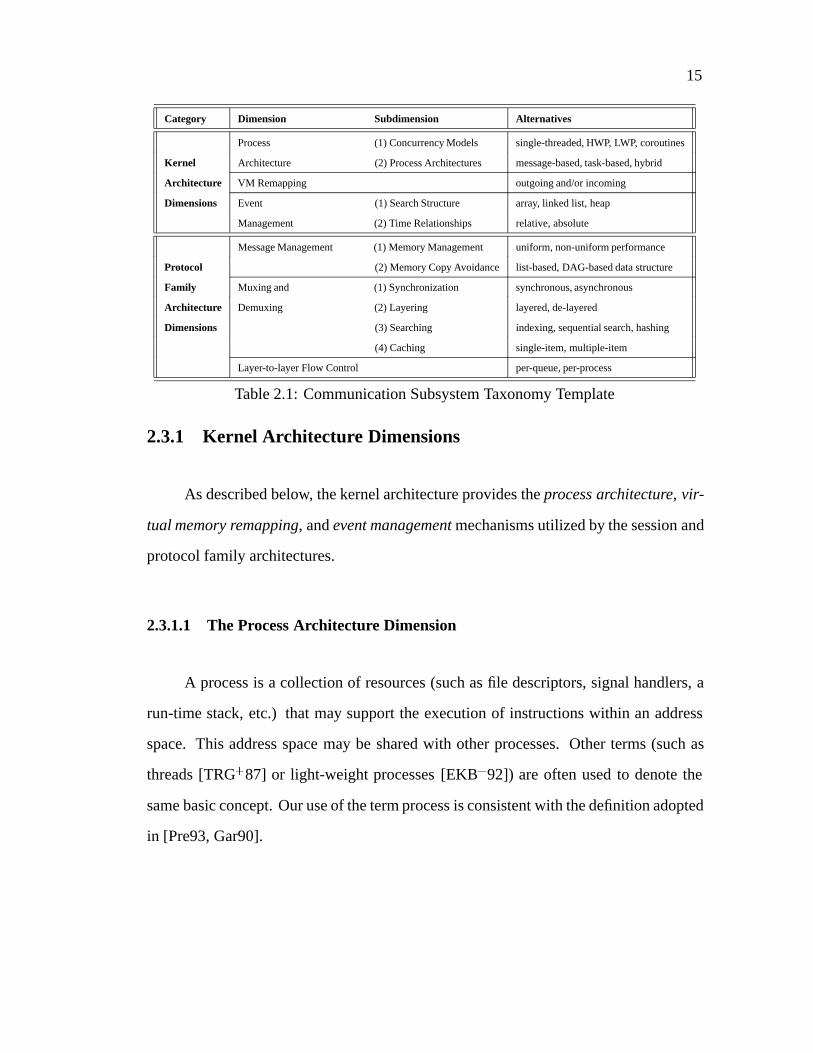
Table 2.1 presents a taxonomy of six key kernel architecture and protocol fam-
ily architecture mechanisms that support the layer-to-layer computing requirements of
protocol graphs end systems. The following section describes the communication sub-
system mechanisms presented in Table 2.1.
3The term “kernel architecture” is used within this chapter to identify mechanisms that form the “nu-
cleus” of the communication subsystem. However, protocol and session architecture components may
reside within an OS kernel (BSD UNIX [LMKQ89], and System V UNIX [Rag93]), in user-space (Mach
[ABG+86] and the Conduit framework [Zwe90]), in either location (thex-kernel [HP91]), or in off-board
processors (Nectar [CSSZ90] and VMP [KC88]).
15
Category Dimension Subdimension Alternatives
Process (1) Concurrency Models single-threaded, HWP, LWP, coroutines
Kernel Architecture (2) Process Architectures message-based, task-based, hybrid
Architecture VM Remapping outgoing and/or incoming
Dimensions Event (1) Search Structure array, linked list, heap
Management (2) Time Relationships relative, absolute
Message Management (1) Memory Management uniform, non-uniform performance
Protocol (2) Memory Copy Avoidance list-based, DAG-based data structure
Family Muxing and (1) Synchronization synchronous, asynchronous
Architecture Demuxing (2) Layering layered, de-layered
Dimensions (3) Searching indexing, sequential search, hashing
(4) Caching single-item, multiple-item
Layer-to-layer Flow Control per-queue, per-process
Table 2.1: Communication Subsystem Taxonomy Template
2.3.1 Kernel Architecture Dimensions
As described below, the kernel architecture provides theprocess architecture, vir-
tual memory remapping, andevent managementmechanisms utilized by the session and
protocol family architectures.
2.3.1.1 The Process Architecture Dimension
A process is a collection of resources (such as file descriptors, signal handlers, a
run-time stack, etc.) that may support the execution of instructions within an address
space. This address space may be shared with other processes. Other terms (such as
threads [TRG+87] or light-weight processes [EKB+92]) are often used to denote the
same basic concept. Our use of the term process is consistent with the definition adopted
in [Pre93, Gar90].

16
A process architecture represents a binding between various units of communica-
tion protocol processing (such as layers, functions, connections, and messages) and var-
ious structural configurations of processes. The process architecture selected for a com-
munication subsystem is one of several factors (along with protocol designs/implementations
and bus, memory, and network interface characteristics) that impact overall application
performance. In addition, the choice of process architecture also influences demulti-
plexing strategies [Fel90] and protocol programming techniques [HP91, Atk88].
Several concurrency models are outlined below. These models form the basis for
implementing the alternative process architectures that are examined in detail following
concurrency model discussion. In order to produce efficient communication subsystems,
it is important to match the selected process architecture with the appropriate concur-
rency model.
(1) Concurrency Models: Heavy-weight processes, light-weight processes, andcorou-
tinesare concurrency models used to implement process architectures. Each model ex-
hibits different performance characteristics and allows different levels of control over
process management activities such as scheduling and synchronization. The following
paragraphs describe key characteristics of each concurrency model:
� Heavy-Weight Processes: A heavy-weight process (HWP) typically resides
in a separate virtual address space managed by the OS kernel and the hardware mem-
ory management unit. Synchronizing, scheduling, and exchanging messages between
HWPs involves context switching, which is a relatively expensive operation in many
operating systems. Therefore, HWPs may not be an appropriate choice for executing
multiple interacting protocol processing activities concurrently.
17
� Light-Weight Processes: Light-weight processes (LWPs) differ from HWPs
since multiple LWPs generallysharean address space by default. This sharing reduces
the overhead of LWP creation, scheduling, synchronization, and communication for the
following reasons:
� Context switching between LWPs is less time consuming than HWPs since there
is less context information to store and retrieve
� It may not be necessary to perform a “mode switch” between kernel- and user-
mode when scheduling and executing an LWP [EKB+92]
� Communication between LWPs may use shared memory rather than message pass-
ing
Note that LWPs may be implemented in kernel-space, user-space, or some hybrid con-
figuration [ABLL92].
�Coroutines: In the coroutine model, a developer (rather than an OS scheduler)
explicitly chooses the next coroutine to run at a particular synchronization point. When
a synchronization point is reached, the coroutine suspends its activities to allow another
coroutine to execute. At some later point, the second coroutine may resume control back
to the first coroutine. Coroutines provide developers with the flexibility to schedule and
execute tasks in any desired manner. However, developers also assume responsibility
for handling all scheduling details, as well as avoiding starvation and deadlock.
Executing protocol and session mechanisms via multiple processes is often less
complicated and error-prone than synchronizing and scheduling these mechanisms man-
ually via coroutines. In addition, coroutines support only interleaved process execution,
which limits the benefits of multi-processing since only one process may run at any given
18
PE
PE
PE
PE
(1) TASK-BASEDPROCESS ARCHITECTURE
active
(2) MESSAGE-BASEDPROCESS ARCHITECTURE
PE PEPE PE
active
active
active
active
active
active
active
MESSAGEOBJECT
PE
PROCESSINGELEMENT
TASKOBJECT
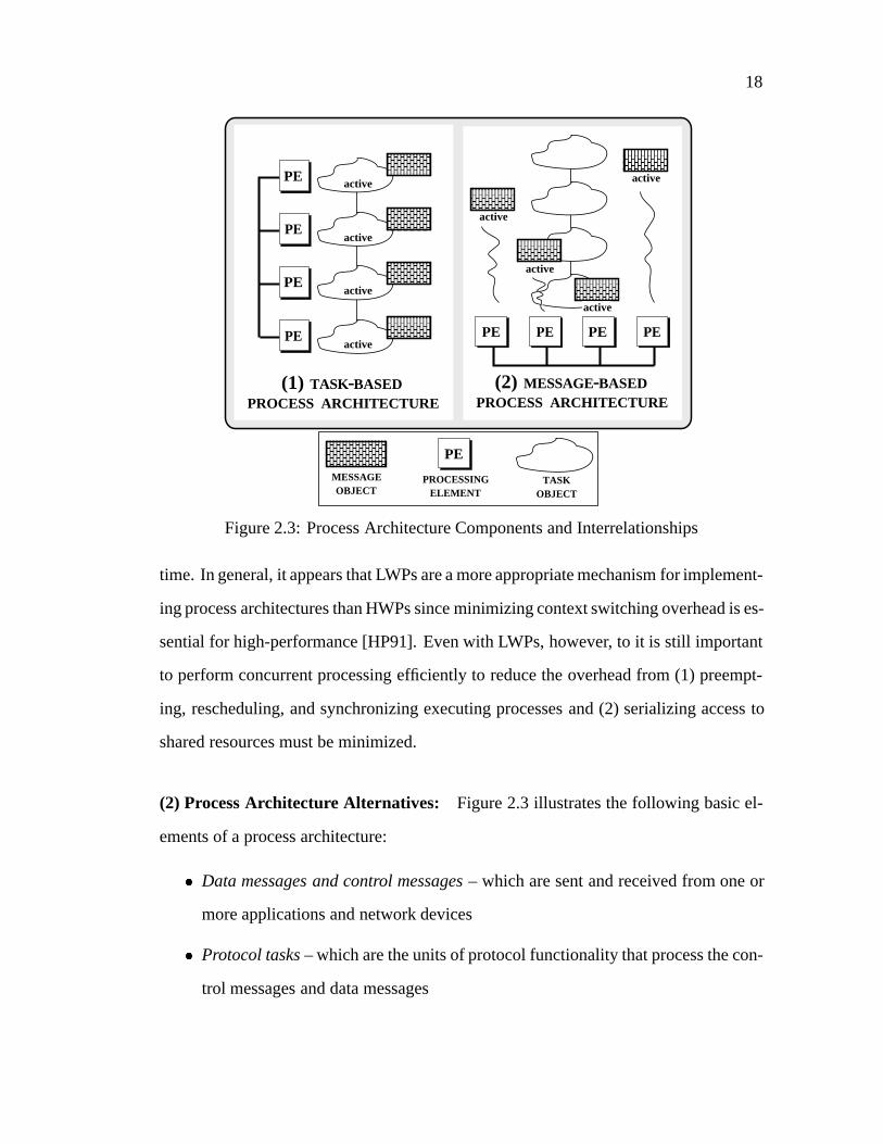
Figure 2.3: Process Architecture Components and Interrelationships
time. In general, it appears that LWPs are a more appropriate mechanism for implement-
ing process architectures than HWPs since minimizing context switching overhead is es-
sential for high-performance [HP91]. Even with LWPs, however, to it is still important
to perform concurrent processing efficiently to reduce the overhead from (1) preempt-
ing, rescheduling, and synchronizing executing processes and (2) serializing access to
shared resources must be minimized.
(2) Process Architecture Alternatives: Figure 2.3 illustrates the following basic el-
ements of a process architecture:
� Data messages and control messages– which are sent and received from one or
more applications and network devices
� Protocol tasks– which are the units of protocol functionality that process the con-
trol messages and data messages

19
APPLICATION INTERFACE
(2) FUNCTIONALPARALLELISM
NETWORK INTERFACE
TO RECEVIER
FROM RECEIVER
(1) LAYERPARALLELISM
NETWORK INTERFACE
LAYER N
LAYER N + 1
APPLICATION INTERFACE
CONGESTION
CONTROLDATA
REXMIT
CONNECTION
MANAGEMENT
FLOW
CONTROL
DATA
XMIT
LAYER N- 1
Figure 2.4: Task-based Process Architectures
� Processing elements(PEs) – which execute protocol tasks
There are two fundamental types of process architectures that structure these basic ele-
ments in different ways:
� Task-based process architectures– which bind one or more PEs to protocol pro-
cessing tasks (shown in Figure 2.3 (1)). In this architecture, tasks are the active
elements, whereas messages processed by the tasks are the passive elements.
� Message-based process architectures– which bind the PEs to the control messages
and the data messages received from applications and network interfaces (shown
in Figure 2.3 (2)). In this architecture, messages are the active elements, whereas
tasks that process the messages are the passive elements.
In terms of functionality, protocol suites (such as the Internet and ISO OSI ref-
erence models) may be implemented using either task-based or message-based process
20
architectures. However, each category of process architecture exhibits different struc-
tural and performance characteristics. The structural characteristics differ according
to (1) the granularity of the unit(s) of protocol processing (e.g., layer or function vs.
connection or message) that execute in parallel, (2) the degree of CPU scalability (i.e.,
the ability to effectively use only a fixed number of CPUs vs. a dynamically scalable
amount), (3) task invocation semantics (e.g.,synchronous vs. asynchronous execution)
and (4) the effort required to design and implement conventional and experimental pro-
tocols and services via a particular process architecture [Atk88]. In addition, different
configurations of application requirements, operating system (OS) and hardware plat-
forms, and network characteristics interact with the structural characteristics of process
architectures to yield significantly different performance results. For instance, on cer-
tain general-purpose OS platforms (such as the System V STREAMS framework on
multi-processor versions of UNIX), fine-grained task-based parallelism results in pro-
hibitively high levels of synchronization overhead [SPY+93]. Likewise, asynchronous,
rendezvous-based task invocation semantics often result in high data movement and
context switching overhead [WF93].
The remainder of this section summarizes the basic process architecture cate-
gories, classifies related work accordingly to these categories, and identifies several key
factors that influence process architecture performance.
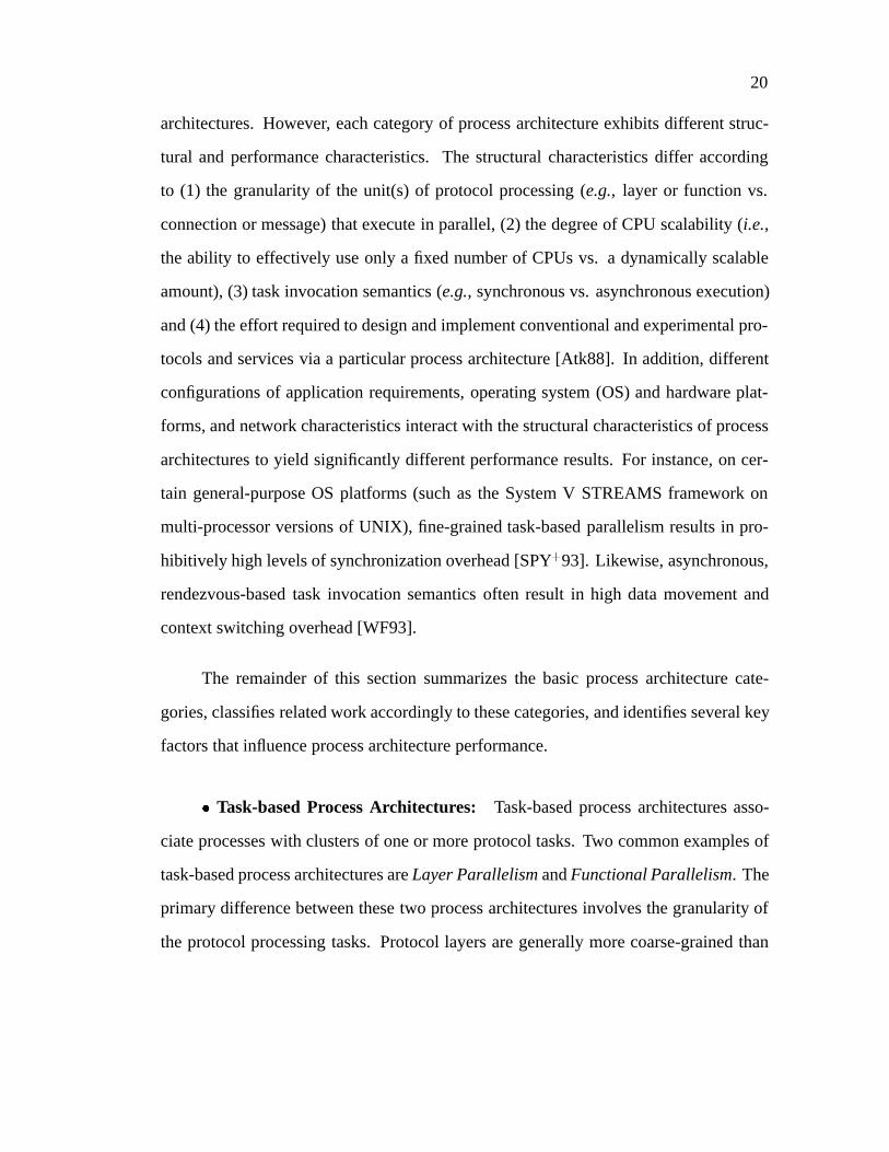
� Task-based Process Architectures: Task-based process architectures asso-
ciate processes with clusters of one or more protocol tasks. Two common examples of
task-based process architectures areLayer ParallelismandFunctional Parallelism. The
primary difference between these two process architectures involves the granularity of
the protocol processing tasks. Protocol layers are generally more coarse-grained than
21
protocol tasks since they cluster multiple tasks together to form a composite service
(such as the end-to-end transport service provided by the ISO OSI transport layer).
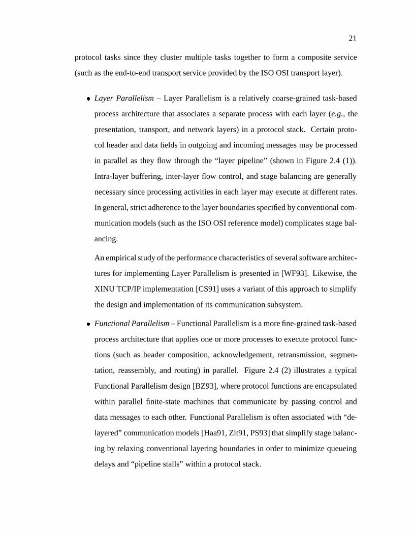
� Layer Parallelism– Layer Parallelism is a relatively coarse-grained task-based
process architecture that associates a separate process with each layer (e.g., the
presentation, transport, and network layers) in a protocol stack. Certain proto-
col header and data fields in outgoing and incoming messages may be processed
in parallel as they flow through the “layer pipeline” (shown in Figure 2.4 (1)).
Intra-layer buffering, inter-layer flow control, and stage balancing are generally
necessary since processing activities in each layer may execute at different rates.
In general, strict adherence to the layer boundaries specified by conventional com-
munication models (such as the ISO OSI reference model) complicates stage bal-
ancing.
An empirical study of the performance characteristics of several software architec-
tures for implementing Layer Parallelism is presented in [WF93]. Likewise, the
XINU TCP/IP implementation [CS91] uses a variant of this approach to simplify
the design and implementation of its communication subsystem.
� Functional Parallelism– Functional Parallelism is a more fine-grained task-based
process architecture that applies one or more processes to execute protocol func-
tions (such as header composition, acknowledgement, retransmission, segmen-
tation, reassembly, and routing) in parallel. Figure 2.4 (2) illustrates a typical
Functional Parallelism design [BZ93], where protocol functions are encapsulated
within parallel finite-state machines that communicate by passing control and
data messages to each other. Functional Parallelism is often associated with “de-
layered” communication models [Haa91, Zit91, PS93] that simplify stage balanc-
ing by relaxing conventional layering boundaries in order to minimize queueing
delays and “pipeline stalls” within a protocol stack.
22
Implementing pipelined, task-based process architectures is relatively straight-
forward since they typically map onto conventional layered communication models us-
ing well-structured “producer/consumer” designs [Atk88]. Moreover, minimal concur-
rency control mechanisms are necessarywithina layer or function since multi-processing
is typically serialized at a service access point (such as the transport or application layer
interface).
�Message-based Process Architectures:Message-based process architectures
associate processes with messages, rather than with protocol layers or protocol tasks.
Two common examples of message-based process architectures areConnectional Par-
allelismandMessage Parallelism. The primary difference between these process archi-
tectures involves the point at which messages are demultiplexed onto a process. Connec-
tional Parallelism demultiplexes all messages bound for the same connection onto the
same process, whereas Message Parallelism demultiplexes messages onto any available
process.
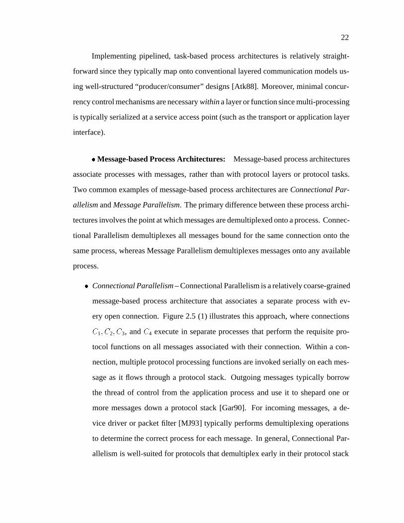
� Connectional Parallelism– Connectional Parallelism is a relatively coarse-grained
message-based process architecture that associates a separate process with ev-
ery open connection. Figure 2.5 (1) illustrates this approach, where connections
C1; C2; C3, andC4 execute in separate processes that perform the requisite pro-
tocol functions on all messages associated with their connection. Within a con-
nection, multiple protocol processing functions are invoked serially on each mes-
sage as it flows through a protocol stack. Outgoing messages typically borrow
the thread of control from the application process and use it to shepard one or
more messages down a protocol stack [Gar90]. For incoming messages, a de-
vice driver or packet filter [MJ93] typically performs demultiplexing operations
to determine the correct process for each message. In general, Connectional Par-
allelism is well-suited for protocols that demultiplex early in their protocol stack

23
APPLICATION INTERFACE
NETWORK INTERFACE
APPLICATION INTERFACE
NETWORK INTERFACE
LAYER
N - 1
LAYER
N
LAYER
N + 1
C1 C2 C3 C4
(1) CONNECTIONAL PARALLELISM
(2) MESSAGEPARALLELISM
LAYER N + 1
LAYER N
LAYER N - 1
Figure 2.5: Message-based Process Architectures
since it is difficult to maintain a strict process-per-connection association across
demultiplexing boundaries [Fel90].
Connectional Parallelism is relatively simple to implement if an OS allows multi-
ple independent system calls, device interrupts, and daemon processes to operate
in parallel [Gar90]. Moreover, if the number of CPUs is greater than or equal
to the number of active connections, Connectional Parallelism also exhibits low
communication, synchronization, and process management overhead [SPY+93]
since all connection context information is localized within a particular process
address space. This localization is beneficial since (1) pointers to messages may
be passed between protocol layers via simple procedure calls (rather than using
more complicated and costly interprocess communication mechanisms) and (2)
cache affinity properties may be preserved since messages are processed largely
within a single CPU cache. The primary limitation of Connectional Parallelism
24
PE PE PE PEPE PE PE PE
SHARED MEMORY
CONCURRENCYDIMENSION
ITERATIVE VS.CONCURRENT DAEMONS
CLASS OFPROTOCOL
CONNECTION-ORIENTED VS.CONNECTIONLESS VS.REQUEST-RESPONSE
CONCURRENCYDIMENSION
ITERATIVE VS.CONCURRENT DAEMONS
NETWORKCHARACTERISTICS
HIGH-SPEED VS. LOW-SPEED
SMALL FRAME VS.LARGE FRAME
CONCURRENCYDIMENSION
ITERATIVE VS.CONCURRENT DAEMONS
APPLICATIONCHARACTERISTICS
NUMBER OF ACTIVE SESSIONS
APPLICATION SERVICE CLASS
CONCURRENCYDIMENSION
ITERATIVE VS.CONCURRENT DAEMONSMESSAGE PASSING VS.
SHARED MEMORY
NUMBER OFPROCESSING ELEMENTS
PLATFORMARCHITECTURE
CHARACTERISTICS
CONCURRENCYDIMENSION
ITERATIVE VS.CONCURRENT DAEMONS
OPERATING SYSTEMCHARACTERISTICS
SYNCHRONIZATION ANDPROCESS MANAGEMENT
OVERHEAD
SINGLE-THREADED VS.MULTI-THREADED KERNEL
CONCURRENCYDIMENSION
ITERATIVE VS.CONCURRENT DAEMONS
TRAFFICCHARACTERISTICS
BURSTY VS. CONTINUOUS
SHORT-DURATION VS.LONG-DURATION
MEMORY AND BUSBANDWIDTH
DIRECTIONALITY
Figure 2.6: External and Internal Factors Influencing Process Architecture Performance
is that it only utilizes multi-processing to improveaggregateend-system perfor-
mance since each individual connection still executes sequentially.
� Message Parallelism– Message Parallelism is a fine-grained message-based pro-
cess architecture that associates a separate process with every incoming or out-
going message. As illustrated in Figure 2.5 (2), a process receives a message
from an application or network interface and performs most or all of the pro-
tocol processing functions on that message. As with Connectional Parallelism,
outgoing messages typically borrow the thread of control from the application
that initiated the message transfer. A number of projects have discussed, simu-
lated, or utilized Message Parallelism as the basis for their process architecture
[JSB90, GNI92, HP91, Mat93, Pre93].

25
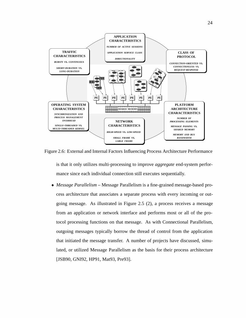
�Process Architecture Performance Factors: The performance of the process archi-
tectures described above is influenced by variousexternalandinternal factors (shown in
Figure 2.6). External factors include (1)application characteristics–e.g.,the number of
simultaneously active connections, the class of service required by applications (such as
reliable/non-reliable and real-time/non-real-time), the direction of data flow (i.e., uni-
directional vs. bi-directional), and the type of traffic generated by applications (e.g.,
bursty vs. continuous), (2)protocol characteristics– e.g., the class of protocol (such
as connectionless, connection-oriented, and request/response) used to implement appli-
cation and communication subsystem services, and (3)network characteristics– e.g.,
attributes of the underlying network environment (such as the delivery of mis-ordered
data due to multipath routing [FM92]). Internal factors, on the other hand, represent
hardware- and software-dependent communication subsystem implementation charac-
teristics such as:
� Process Management Overhead– Process architectures exhibit different context
switching and scheduling costs related to (1) the type of scheduling policies em-
ployed (e.g., preemptive vs. non-preemptive), (2) the protection domain (e.g.,
user-mode vs. kernel-mode) in which tasks within a protocol stack execute, and
(3) the number of available CPUs. In general, a context switch is triggered when
(1) one or more processes must sleep awaiting certain resources (such as memory
buffers or I/O devices) to be come available, (2) preemptive scheduling is used
and a higher priority process becomes runnable, or (3) when a currently executing
process exceeds its time slice. Depending on the underlying OS and hardware
platform, a context switch may be relatively time consuming due to the flushing
of register windows, instruction and data caches, instruction pipelines, and trans-
lation look-aside buffers [MB91].
26
� Synchronization Overhead– Implementing communication protocols that execute
correctly on multi-processor platforms requires synchronization mechanisms that
serialize access to shared objects such as messages, message queues, protocol con-
text records, and demultiplexing tables. Certain protocol and process architec-
ture combinations (such as implementing connection-oriented protocols via Mes-
sage Parallelism) may incur significant synchronization overhead from managing
locks associated with these shared objects [Mat93]. In addition to reducing over-
all throughput, synchronization bottlenecks resulting from lock contention lead to
unpredictable response times that complicate the delivery of constrained-latency
applications. Other sources of synchronization overhead involve contention for
shared hardware resources such as I/O buses and global memory [DAPP93]. In
general, hardware contention represents an upper limit on the benefits that may
accrue from multi-processing [WF93].
� Communication Overhead– Task-based process architectures generally require
some form of interprocess communication to exchange messages between proto-
col processing components executing on separate CPUs. Communication costs
are incurred by memory-to-memory copying, message manipulation operations
(such as checksum calculations and compression), and general message pass-
ing overhead resulting from synchronization and process management operations.
Common techniques for minimizing communication overhead involve (1) buffer
management schemes that minimize data copying [HMPT89] and attempt to pre-
serve cache affinity properties when exchanging messages between CPUs with
separate instruction and data caches, (2) integrated layer processing techniques
[CT90], and (3) single-copy network/host interface adapters [WBC+93].
� Load Balancing– Certain process architectures (such as Message Parallelism)
have the potential for utilizing multiple CPUs equitably, whereas others (such as

27
Connectional, Layer, and Functional Parallelism) may under- or over-utilize the
available CPUs under certain circumstances (such as bursty network and applica-
tion traffic patterns or improper stage balancing).
2.3.1.2 The Virtual Memory (VM) Remapping Dimension
Regardless of the process architecture, minimizing the amount of memory-to-
memory copying in a communication subsystem is essential to achieve high performance
[WM87]. In general, data copying costs provide an upper bound on application through-
put [CT90]. As described in Section 2.3.2.1 below, selecting an efficient message man-
agement mechanism is one method for reducing data copying overhead. A related ap-
proach described in this section uses virtual memory optimizations to avoid copying
data altogether. For example, in situations where data must be transferred from one
address space to another, the kernel architecture may remap the virtual memory pages
by marking their page table entries as being “copy-on-write.” Copy-on-write schemes
physically copy memory only if a sender or receiver changes a page’s contents.
Page remapping techniques are particularly useful for transferring large quantities
of data between separate address spaces on the same host machine. An operation that
benefits from this technique involves data transfer between user-space and kernel-space
at the application interface. Rather than physically copying data from application buffers
to kernel buffers, the OS may remap application pages into kernel-space instead.
Page remapping schemes are often difficult to implement efficiently in the context
of communication protocols, however. For example, most remapping schemes require
the alignment of data in contiguous buffers that begin on page boundaries. These align-
ment constraints are complicated by protocol operations that significantly enlarge or
shrink the size of messages. This operations include message de-encapsulation (i.e.,
28
stripping headers and trailers as messages ascend through a protocol graph), presenta-
tion layer expansion [CT90] (e.g.,uncompressing or decrypting an incoming message),
and variable-size header options (such as those proposed to handle TCP window scaling
for long-delay paths [JBB92]). Moreover, remapping may not be useful if the sender or
receiver writes on the page immediately since a separate copy must be generated any-
way [LMKQ89]. In addition, for small messages, more overhead may be incurred by
remapping and adjusting page table entries, compared with simply copying the data in
the first place.
2.3.1.3 The Event Management Dimension
Event management mechanisms provided by the kernel architecture support time-
related services for user applications and other mechanisms in a communication subsys-
tem. In general, three basic operations are exported by an event manager:
1. Registering subroutines (called “event handlers”) that will be executed at some
user-specified time in the future
2. Canceling a previously registered event handler
3. Invoking an event handler when its expiration time occurs
The data structures and algorithms that implement an event manager must be selected
carefully so that all three types of operations are performed efficiently. In addition, the
variance among different event handler invocation times should be minimized. Reduc-
ing variance is important for constrained latency applications, as well as for communi-
cation subsystems that register and execute a large number of event handlers during a
given time period.

29
At the session architecture level, protocol implementations may use an event man-
ager to perform certain time-related activities on network connections. In this case, a re-
liable connection-oriented protocol implementation registers a “retransmission-handler”
with the event manager when a protocol segment is sent. The expiration time for this
event is usually based on a time interval calculated from the round-trip packet estimate
for that connection. If the timer expires, the event manager invokes the handler to re-
transmit the segment. The retransmission event handler will be canceled if an acknowl-
edgement for the segment arrives before the timer expires.
Mechanisms for implementing event managers includedelta lists [CS91], tim-
ing wheels[VL87], and heap-based [BL88] and list-based [LMKQ89]callout queues.
These mechanisms are built atop a hardware clock mechanism. On each “clock-tick”
the event manager checks whether it is time to execute any of its registered events. If
one or more events must be run, the event manager invokes the associated event han-
dler. The different event manager mechanisms may be distinguished by the following
two dimensions:
(1) Search Structure: Several search structures are commonly used to implement dif-
ferent event management mechanisms. One approach is to sort the events by their time-
to-execute value and store them in an array. A variant on this approach (used bydelta
lists and list-basedcallout queues) replaces the array with a sorted linked list to reduce
the overhead of adding or deleting an event [CS91]. Another approach is to use a heap-
based priority queue [BL88] instead of a sorted list or array. In this case, the average-
and worst-case time complexity for inserting or deleting an entry is reduced fromO(n)
to O(lgn). In addition to improving average-case performance, heaps also reduce the
variance of event manager operations.
30
(2) Time Relationships: Another aspect of event management involves the “time re-
lationships,” (i.e., absolutevs. relative time) that are used to represent an event’s exe-
cution time. Absolute time is generally computed in terms of a value returned by the
underlying hardware clock. Heap-based search structures typically use absolute time
due to the comparison properties necessary to maintain a heap as a partially-ordered,
almost-complete binary tree. In contrast, relative-time may be computed as an offset
from a particular starting point and is often used for a sorted linked list implementation.
For example, if each item’s time is stored as adelta relative to the previous item, the
event manager need only examine the first element on every clock-tick to determine if
it should execute the next registered event handler.
2.3.2 Protocol Family Architecture Dimensions
Protocol family architecture mechanisms pertain primarily to network protocols
and distributed applications. In contrast, kernel architecture mechanisms are also uti-
lized by many other applications and OS subsystems. The protocol family architecture
provides intra-protocol and inter-protocol mechanisms that may be reused by protocols
in many protocol families. Intra-protocol mechanisms involve the creation and deletion
of sessions, whereas inter-protocol mechanisms involve message management, multi-
plexing and demultiplexing of messages, and layer-to-layer flow control. This section
examines the inter-protocol mechanisms.
2.3.2.1 The Message Management Dimension
Communication subsystems provide mechanisms for exchanging data and control
messages between communicating entities on local and remote end systems. Standard
31
message management operations include (1) storing messages in buffers as they are re-
ceived from network adapters, (2) adding and/or removing headers and trailers from
messages as they pass through a protocol graph, (3) fragmenting and reassembling mes-
sages to fit into network maximum transmission units, (4) storing messages in buffers for
transmission or retransmission, and (5) reordering messages received out-of-sequence
[JSB90]. To improve efficiency, these operations must minimize the overhead of dy-
namic memory management and also avoid unnecessary data copying, as described in
the following paragraphs:
(1) Dynamic Memory Management: Traditional data network traffic exhibits a bi-
modal distribution of sizes, ranging from large messages for bulk data transfer to small
messages for remote terminal access [CDJM91]. Therefore, message managers must be
capable of dynamically allocating, deallocating, and coalescing fixed-sized and variable-
sized blocks of memory efficiently. However, message management schemes are often
tuned for a particular range of message sizes. For instance, the BSD UNIX message
management facility divides its buffers into 112 byte and 1,024 byte blocks. This leads to
non-uniform performance behavior when incoming and outgoing messages vary in size
between small and large blocks. As discussed in [HP91], more uniform performance
is possible if message managers support a wide range of message sizes as efficiently as
they support large and/or small messages.
(2) Memory Copy Avoidance: As mentioned in Section 2.3.1.2, memory-to-memory
copying is a significant source of communication subsystem overhead. Naive mes-
sage managers that physically copy messages between each protocol layer are pro-
hibitively expensive. Therefore, more sophisticated implementations avoid or minimize
memory-to-memory copying via techniques such asbuffer-cut-through[WM89, ZS90]
and lazy-evaluation[HMPT89]. Buffer-cut-through passes messages “by reference”
32
through multiple protocol layers to reduce copying. Likewise, lazy-evaluation tech-
niques use reference counting and buffer-sharing to minimize unnecessary copying.
These schemes may be combined with the virtual memory remapping optimizations
described in Section 2.3.1.2.
Message managers use different methods to reduce data copying and facilitate
buffer sharing. For instance, BSD and System V UNIX attach multiple buffers together
to form linked-lists of message segments. Adding data to the front or rear of a buffer list
does not require any data copying since it only relinks pointers. An alternative approach
uses adirected-acyclic-graph(DAG)-based data structure [HMPT89]. A DAG allows
multiple “parents” to share all or part of a message stored in a single “child.” Therefore,
this method improves data sharingbetweenlayers in a highly-layered protocol graph.
This is important for reliable protocols (such as RPC or TCP) that maintain “logical”
copies of messages at certain protocol layers in case retransmission is necessary.
2.3.2.2 The Multiplexing and Demultiplexing Dimension
Multiplexing (muxing) and demultiplexing (demuxing) mechanisms select which
of the sessions in an adjacent protocol layer will receive an incoming or outgoing mes-
sage. A sender typically performs multiplexing, which directs outgoing messages ema-
nating from some number of higher-layer sessions onto a smaller number of lower-layer
sessions [Ten89]. Conversely, a receiver performs demultiplexing, which directs in-
coming messages up to their associated sessions. Multiplexing and demultiplexing are
orthogonal to data copying; depending on the message management scheme, messages
need not be copied as they are multiplexed and demultiplexed throughout a protocol
graph [HMPT89].

33
Since senders generally possess knowledge of their entire transfer context (such
as message destination address(es) like connection identifiers, port numbers, and/or In-
ternet IP addresses [CT90], as well as which network interfaces to use) multiplexing
may be less costly than demultiplexing. In contrast, when a network adapter receives
an incoming message it generally has no prior knowledge of the message’s validity or
eventual destination. To obtain this information, a receiver must inspect the message
header and perform demultiplexing operations that select which higher-layer protocol
session(s) should receive the message.
Multiplexing and demultiplexing may be performed several times as messages
move to and from network adapters, protocol layers, and user applications. Depending
on the process architecture selected for a communication subsystem, multiplexing and
demultiplexing activities may incur high synchronization and context switching over-
head since one or more processes may need to be awakened, scheduled, and executed.
As described below, four key multiplexing and demultiplexing dimensions include
synchronization, layering, searching, andcaching:
(1) Synchronization: Multiplexing and demultiplexing may occur either synchronously
or asynchronously, depending primarily on whether the communication subsystem uses
a task-based or message-based process architecture. For example, message-based pro-
cess architectures (such as thex-kernel) typically use synchronous multiplexing and
demultiplexing since messages do not pass between separate process address spaces.
Therefore,intra-processupcalls and subroutine calls are used to transfer messages up
and down a protocol graph rather than more expensive asynchronousinter-processcom-
munication techniques such as message queues.

34
NETWORK INTERFACE NETWORK INTERFACENETWORK INTERFACE
(2) DE-LAYERED MULTIPLEXING
AND DEMULTIPLEXING
(1) LAYERED MULTIPLEXING
AND DEMULTIPLEXING
NETWORK INTERFACE
P1
TPA
NPA
PROCESSESMESSAGE
QUEUES
SUBROUTINE
CALLS
TPA TPB
PROTOCOLS AND
SESSIONS
NPA
P1 P2 P3 P4 P2
TPA
NPA
P3
TPB
NPA
P4
TPB
NPA
Figure 2.7: Layered and De-layered Multiplexing and Demultiplexing
In contrast, task-based process architectures (such as F-CSS [ZST93]) utilize asyn-
chronous multiplexing and demultiplexing. In this scheme, message queues are used to
buffer data passed between processes that implement a layered protocol graph. Since
message queues do not necessarily block the sender, it is possible to concurrently pro-
cess messages in each protocol layer, which potentially increases throughput. However,
this advantage may be offset by the additional context switching and data movement
overhead incurred to move messages between separate CPUs [Sch94b].
(2) Layering: As shown in Figure 2.7 (1), multiplexing and demultiplexing may oc-
cur multiple times as messages traverse up or down a protocol graph. Thislayeredap-
proach differs from thede-layeredapproach shown in Figure 2.7 (2). In the de-layered
approach, multiplexing and/or demultiplexing is performed only once, usually at either
the highest- or lowest-layer of a protocol graph.
35
The use of layered multiplexing and demultiplexing provides several benefits [Ten89].
First, it promotes modularity, since the interconnected layer components interoperate
only at well-defined “service access points” (SAPs). This enables mechanisms offered
at one layer to be developed independently from other layers. Second, it conserves
lower-layer resources like active virtual circuits by sharing them among higher-layer
sessions. Such sharing may be useful for high-volume, wide-area, leased-line commu-
nication links where it is expensive to reestablish a dedicated virtual circuit for each
transmitted message. Finally, layered multiplexing and demultiplexing may be useful
for coordinating related streams in multimedia applications (such as interactive tele-
conferencing) since messages synchronize at each SAP boundary.
The primary disadvantages of layered multiplexing and demultiplexing arise from
the additional processing incurred at each layer. For example, in a task-based process
architecture, multiple levels of demultiplexing may increase context switching and syn-
chronization overhead. This overhead also enlarges packet latency variance (known
as “jitter”), which is detrimental to the quality-of-service for delay- and jitter-sensitive
multimedia applications such as interactive voice or video.
De-layered multiplexing and demultiplexing generally decreases jitter since there
is less contention for communication subsystem resources at a single lower-layer SAP
from multiple higher-layer data streams [Ten89]. However, the amount of context in-
formation stored within every intermediate protocol layer increases since sessions are
not shared [Fel90]. In addition, de-layering expands the degree of demultiplexing at
the lowest layer. This violates protocol layering characteristics found in conventional
communication models (such as the ISO OSI reference model) since the lowest layer
is now responsible for demultiplexing on addresses (such as connection identifiers or
port numbers) that are actually associated with protocols several layers above in a pro-
tocol graph. Packet filters [MJ93] are a technique used to address this issue. Packet
36
filters allow applications and higher-level protocols to “program” a network interface so
that particular types of incoming PDUs are demultiplexed directly to them, rather than
passing through a series of intervening protocol layers first.
Note that the use of de-layered multiplexing and demultiplexing interacts with the
choice of process architecture. For example, Connectional Parallelism is enhanced by
protocols that demultiplex early in their protocol stack since it is difficult to maintain a
strict process-per-connection association across demultiplexing boundaries [Fel90].
(3) Searching: Some type of search algorithm is required to implement multiplexing
and demultiplexing schemes. Several common search algorithms includedirect index-
ing, sequential search, andhashing. Each algorithm uses anexternal identifiersearch
key (such as a network address, port number, or type-of-service field) to locate aninter-
nal identifier(such as a pointer to a protocol control block or a network interface) that
specifies the appropriate session context record.
Transport protocols such as TP4 and VMTP pre-computeconnection identifiers
during connection establishment to simplify subsequent demultiplexing operations. If
these identifiers have a small range of values, a demultiplexing operation may simply
index directly into an array-based search structure to locate the associated session con-
text record. Alternatively, a sequential search may be used if a protocol does not support
connection identifiers, or if the range of identifier values is large and sparse. For exam-
ple, BSD UNIX demultiplexes TCP and UDP associations by performing a sequential
search on external identifiers represented by a<source addr, source port, destination
port> tuple. Although sequential search is simple to implement, it does not scale up
well if the communication subsystem has hundreds or thousands of external identifiers
representing active connections. In this case, a more efficient search algorithm (such as
bucket-chained hashing) may be required.

37
(4) Caching: Several additional optimizations may be used to augment the search
algorithms discussed above. These optimizations include (1) single- or multiple-item
caches and (2) list reorganization heuristics that move recently accessed control blocks
to the front of the search list or hash bucket-chain. A single-item cache is relatively effi-
cient if the arrival and departure of application data exhibit “message-train” behavior. A
message-train is a sequence of back-to-back messages that are all destined for the same
higher-level session. However, single-item caching is insufficient if application traf-
fic behavior is less uniform [MD91]. When calculating how well a particular caching
scheme affects the cost of demultiplexing it is important to consider (1) themiss ra-
tio, which represents how many times the desired external identifier isnot in the cache
and (2) the number of list entries that must be examined when a cache miss occurs. In
general, the longer the search list, the higher the cost of a cache miss.
The choice of search algorithm and caching optimization impacts overall com-
munication subsystem and protocol performance significantly. When combined with
caching, hashing produces a measurable improvement for searching large lists of con-
trol blocks that correspond to active network connections [HP91].
2.3.2.3 The Layer-to-Layer Flow Control Dimension
Layer-to-layer flow control regulates the rate of speed and amount of data that is
processed at various levels in a communication subsystem. For example, flow control is
performed at the application interface by suspending user processes that attempt to send
and/or receive more data than end-to-end session buffers are capable of handling. Like-
wise, within the protocol family architecture level, layer-to-layer flow control prevents
higher-layer protocol components from flooding lower-layers with more messages than
they are equipped to process and/or buffer.
38
Layer-to-layer flow control has a significant impact on protocol performance. For
instance, empirical studies [CWWS92] demonstrate the importance of matching buffer
sizes and flow control strategies at each layer in the protocol family architecture. In-
efficiencies may result if buffer sizes are not matched appropriately in adjacent layers,
thereby causing excessive segmentation/reassembly and additional transmission delays.
Two general mechanisms for controlling the layer-to-layer flow of messages in-
clude theper-queueflow control andper-processflow control schemes outlined below:
� Per-Queue Flow Control: Flow control may be implemented by enforcing
a limit on the number of messages or total number of bytes that are queued between
sessions in adjacent protocol layers. For example, a task-based process architecture
may limit the size of the message queues that store information passed between adjacent
sessions and/or user processes. This approach has the advantage that it enables control
of resource utilization at a fairly fine-grain level (such as per-connection).
� Per-Process Flow Control: Flow control may also be performed in a more
coarse-grained manner at the per-process level. This approach is typically used by
message-based process architectures. For example, in thex-kernel, an incoming mes-
sage is discarded at a network interface if a light-weight process is not available to shep-
ard an incoming message up through a protocol graph. The advantage of this approach is
that it reduces queueing complexity at higher-layers. However, it may unfairly penalize
connections that are not responsible for causing message congestion on an end system.

39
2.4 Survey of Existing OS Communication Subsystem Ar-
chitectures
A number of framework have emerged to simplify the development and config-
uration of communication subsystems by inter-connecting session and protocol family
architecture components. In general, these frameworks encourage the development of
standard communication-related components (such as message managers, timer-based
event dispatchers, and connection demultiplexors [HMPT89], and various protocol func-
tions [SSS+93]) by decoupling protocol processing functionality from the surrounding
framework infrastructure. This section surveys the communication subsystem architec-
tures for the System V UNIX, BSD UNIX,x-kernel, and Choices operating systems.
Unless otherwise noted, the systems described include System V Release 4, BSD 4.3
Tahoe,x-kernel 3.2, and Choices 6.16.91. Section 2.4.1 gives a brief summary of each
system. Section 2.4.2 compares and contrasts each system using the taxonomy dimen-
sions listed in Table 2.1.
2.4.1 System Overviews
This section outlines the primary software components and process architectures
for each surveyed communication subsystem in order to highlight the design decisions
made by actual systems. In addition, a communication subsystemprofilecorresponding
to the taxonomy depicted in Table 2.1 is presented along with each overview (note that
ND stands for “not defined”).
2.4.1.1 System V STREAMS

40
Process Architecture(1) coroutines, (2) task-based (process-per-module)
VM Remapping none
Event Management (1) absolute, (2) heap
Message Buffering (1) uniform, (2) list-based
Muxing/Demuxing (1) asynchronous, (2) layered, (3) ND, (4) ND
Flow Control per-queue
Table 2.2: STREAMS Profile
The System V STREAMS architecture emphasizes modular components that pos-
sess uniform interfaces. It was initially developed to support the flexible composition
of terminal drivers in UNIX [Rit84]. It was later extended to support network protocols
and local IPC viamultiplexor driversand STREAMpipes, respectively [Rag93]. The
Table 2.2 illustrates the communication subsystem profile for System V STREAMS.
In the discussion below, the uppercase term “STREAMS” refers to the overall Sys-
tem V communication subsystem mechanism, whereas the term “Stream” refers to a
full-duplex protocol processing and data transfer path between a user application and a
device driver.
As shown in Figure 2.8, the main components in the System V STREAMS ar-
chitecture include STREAMheads, STREAM modules, STREAM multiplexors, and
STREAM drivers. A STREAM head segments the user data into discrete messages.
These messages are passed “downstream” from the STREAM head though zero or more
STREAM modules and multiplexors to the STREAM driver, where they are transmitted
by a network adapter to the appropriate network. Likewise, the driver also receives in-
coming messages from the network. These messages are passed “upstream” through the
modules to the STREAM head, where a user process may retrieve them. STREAM mod-
ules and multiplexors may be inserted and/or removed dynamically between the head
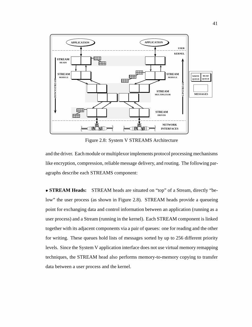
41
WRITEQUEUE
READQUEUE
STREAMDRIVER
WRITEQUEUE
READQUEUE
APPLICATION
STREAMMODULE
USER
KERNEL
UP
ST
RE
AM
STREAMMULTIPLEXOR
APPLICATION
WRITEQUEUE
READQUEUE
STREAMHEADS
STREAMMODULE
DO
WN
ST
RE
AM
NETWORK
INTERFACES
WRITEQUEUE
READQUEUE
WRITEQUEUE
READQUEUE
WRITE
QUEUE
READ
QUEUE
MESSAGES
WRITEQUEUE
READQUEUE
WRITEQUEUE
READQUEUE
WRITEQUEUE
READQUEUE
Figure 2.8: System V STREAMS Architecture
and the driver. Each module or multiplexor implements protocol processing mechanisms
like encryption, compression, reliable message delivery, and routing. The following par-
agraphs describe each STREAMS component:
� STREAM Heads: STREAM heads are situated on “top” of a Stream, directly “be-
low” the user process (as shown in Figure 2.8). STREAM heads provide a queueing
point for exchanging data and control information between an application (running as a
user process) and a Stream (running in the kernel). Each STREAM component is linked
together with its adjacent components via a pair of queues: one for reading and the other
for writing. These queues hold lists of messages sorted by up to 256 different priority
levels. Since the System V application interface does not use virtual memory remapping
techniques, the STREAM head also performs memory-to-memory copying to transfer
data between a user process and the kernel.
42
�STREAM Modules: Each STREAM module performs its protocol processing oper-
ations on the data it receives before forwarding the data to the next module. In this way,
STREAM modules are analogous to “filter” programs in a UNIX shell pipeline. Unlike
a UNIX pipeline, however, data is passed as discrete messages between modules, rather
than as a byte-stream. Applications may “push” and/or “pop” STREAM modules on or
off a Stream dynamically in “last-in, first-out” (LIFO) order. Each read and write queue
in a module contains pointers to subroutines that (1) implement the module’s protocol
processing operations and (2) regulate layer-to-layer message flow between modules.
Two subroutines associated with each queue are calledput andservice . The
put subroutine typically performs synchronous message processing when invoked by
an adjacent queue (e.g.,when a user process sends a message downstream or a message
arrives on a network interface). It performs protocol processing operations that must be
invoked immediately (such as handling high-priority TCP “urgent data” messages).
Theservice subroutine, on the other hand, is used for protocol operations that
either do not execute in a short, fixed amount of time (e.g., performing a three-way
handshake to establish an end-to-end network connection) or that will block indefinitely
(e.g.,due to layer-to-layer flow control). Theservice subroutines in adjacent modules
generally interact in a coroutine-like manner. For example, when a queue’sservice
subroutine is run, it performs protocol processing operations on all the messages waiting
in the queue. When theservice subroutine completes, the messages it processed will
have been passed to the appropriate adjacent STREAM module in the Stream. Next,
theservice routine for any STREAM modules that now have new messages in their
queue(s) is scheduled to run.
�STREAM Multiplexors: STREAM multiplexors may be linked between a STREAM
head and a STREAM driver, similar to STREAM modules. Unlike a STREAM module,
43
however, a multiplexor driver is linked withmultipleStreams residing directly “above”
or “below” it. Multiplexors are used to implement network protocols such as TCP and
IP that receive data from multiple sources (e.g.,different user processes) and send data
to multiple sources (e.g.,different network interfaces).
� STREAM Drivers: STREAM drivers are connected at the “bottom” of a Stream.
They typically manage hardware devices, performing activities such as handling net-
work adapter interrupts and converting incoming packets into messages suitable for up-
stream modules and multiplexors.
�Messages: Data is passed between STREAMS components in discrete chunks via an
abstraction called amessage. Messages consist of acontrol block and one or moredata
blocks. The control block typically contains bookkeeping information such as destina-
tion addresses and length fields). The data blocks generally contain the actual message
contents,i.e., its “payload.”
To minimize memory-to-memory copying costs, pointers to message blocks are
passed upstream and downstream. A message is represented as a<message control
block, data control block, variable length data buffer> tuple. This tuple minimizes
memory-to-memory copying costs by sharing a common<data buffer> among several
<message control block, data control block> portions.
The traditional System V STREAMS communication subsystem supports a vari-
ant of the task-based process architecture known as “process-per-module” that associates
a “logical” process with a STREAM module’sservice subroutine. This process-per-
module approach is implemented by scheduling and executing theservice subrou-
tines associated with the read and write queues in a STREAM module. Originally, the
service procedures were run only at certain times (such as just before returning from

44
a system call and just before a user process was put to sleep). Unfortunately, this de-
sign made it difficult to support applications with isochronous or constrained latency
requirements since STREAM modules were not scheduled to run with any precise real-
time guarantees. In addition, these subroutines execute outside the context of any kernel
or user process, thereby avoiding the standard UNIX kernel process scheduling mech-
anism. This design represents an effort to (1) minimize the kernel state information re-
quired for process management and (2) reduce context switching overhead when moving
messages between module queues.
Many STREAMS implementations [EKB+92, Gar90, Pre93, SPY+93] utilize shared
memory, symmetric multi-processing capabilities within a multi-threaded kernel ad-
dress space. These implementations supports various levels of STREAMS concurrency.
These concurrency levels range from relatively fine-grain parallelism (such asqueue-
level with one light-weight process (LWP) for the STREAM module read queue and
one LWP for the STREAM module write queue andqueue-pair-levelwith one LWP
shared by a STREAM module queue pair) to more coarse-grained approaches (such
asmodule-levelwith one LWP shared across all instances of a STREAM module and
module-class-levelwith one LWP shared across a particular class of STREAM mod-
ules).
2.4.1.2 BSD UNIX Network Subsystem
BSD UNIX provides a communication subsystem framework that supports mul-
tiple protocol families such as the Internet, XNS, and OSI protocols [LMKQ89]. BSD
provides a general-purpose application interface calledsockets. Sockets are bi-directional
communication channels that transfer data between unrelated processes on local and re-
mote hosts. Table 2.3 illustrates the communication subsystem profile for BSD UNIX.
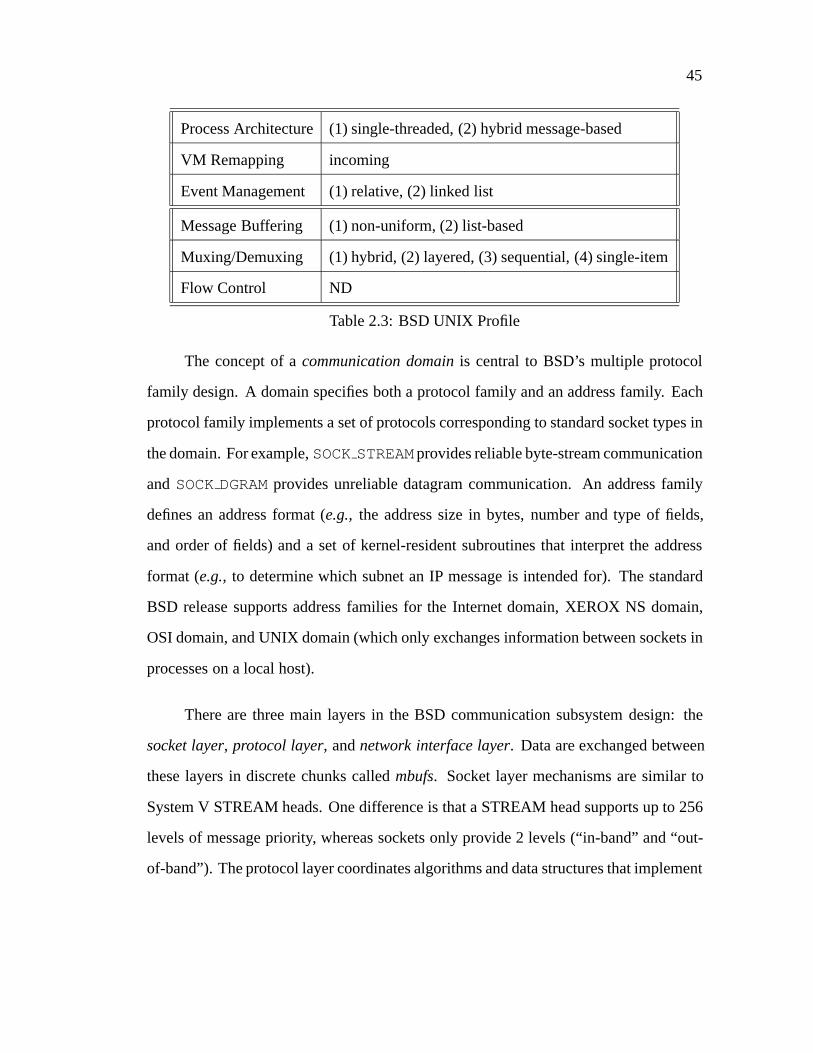
45
Process Architecture(1) single-threaded, (2) hybrid message-based
VM Remapping incoming
Event Management (1) relative, (2) linked list
Message Buffering (1) non-uniform, (2) list-based
Muxing/Demuxing (1) hybrid, (2) layered, (3) sequential, (4) single-item
Flow Control ND
Table 2.3: BSD UNIX Profile
The concept of acommunication domainis central to BSD’s multiple protocol
family design. A domain specifies both a protocol family and an address family. Each
protocol family implements a set of protocols corresponding to standard socket types in
the domain. For example,SOCKSTREAMprovides reliable byte-stream communication
andSOCKDGRAMprovides unreliable datagram communication. An address family
defines an address format (e.g., the address size in bytes, number and type of fields,
and order of fields) and a set of kernel-resident subroutines that interpret the address
format (e.g., to determine which subnet an IP message is intended for). The standard
BSD release supports address families for the Internet domain, XEROX NS domain,
OSI domain, and UNIX domain (which only exchanges information between sockets in
processes on a local host).
There are three main layers in the BSD communication subsystem design: the
socket layer, protocol layer, andnetwork interface layer. Data are exchanged between
these layers in discrete chunks calledmbufs. Socket layer mechanisms are similar to
System V STREAM heads. One difference is that a STREAM head supports up to 256
levels of message priority, whereas sockets only provide 2 levels (“in-band” and “out-
of-band”). The protocol layer coordinates algorithms and data structures that implement
46
the various BSD protocol families. The network interface layer provides a software ve-
neer for accessing the underlying network adapter hardware. The following paragraphs
describe the major BSD protocol layer components in detail:
� The Socket Layer: A socket is atypedobject that represents a bi-directional end-
point of communication. Sockets provide a queueing point for data that is transmitted
and received between user applications running as user processes and the protocol layers
running in the OS kernel. Open sockets are identified viasocket descriptors. These
descriptors index into a kernel table containing socket-related information such as send
and receive buffer queues, the socket type, and pointers to the associated protocol layer.
When a socket is created, a new table slot is initialized based on the specified “socket
type” (e.g.,SOCKSTREAMor SOCKDGRAM). Socket descriptors share the same name
space as UNIX file descriptors. This allows many UNIX applications to communicate
transparently using different kinds of devices such as remote network connections, files,
terminals, printers, and tape drives.
� The Protocol Layer: BSD’s protocol layer contains multiple components organized
using a dispatch table format. Unlike STREAMS, the BSD network architecture does
not allow arbitrary configuration of protocol components at run-time. Instead, protocol
families are created by associating certain components with one another when a kernel
image is statically linked.
In the Internet protocol family, the TCP component is linked above the IP compo-
nent. Each protocol component stores session context information incontrol blocksthat
represent open end-to-end network sessions. Internet domain control blocks include the
inpcb (which stores the source and destination host addresses and port numbers) and
the tcpcb (which stores the TCP state machine variables such as sequence numbers,
retransmission timer values, and statistics for network management). Eachinpcb also

47
contains links to siblinginpcbs (which store information on other active network ses-
sions in the protocol layer), back-pointers to the socket data structure associated with the
protocol session, and other relevant information such as routing-table entries or network
interface addresses.
� The Network Interface Layer: Messages arriving on network interfaces are han-
dled by a software interrupt-based mechanism, as opposed to dedicating a separate ker-
nel “process” to perform network I/O. Interrupts are used for two primary reasons: (1)
they reduce the context switching overhead that would result from using separate pro-
cesses and (2) the BSD kernel is not multi-threaded. There are two levels of interrupts:
SPLNET and SPLIMP. SPLNET has higher priority and is generated when a network
adapter signals that a message has arrived on an interface. However, since hardware
interrupts cannot be masked for very long without causing other OS devices to timeout
and fail, a lower priority software interrupt level named SPLIMP actually invokes the
higher-layer protocol processing.
For example, when an SPLNET hardware interrupt occurs, the incoming message
is placed in the appropriate network interface protocol queue (e.g.,the queue associated
with the IP protocol). Next, an SPLIMP software interrupt is posted, informing the
kernel that higher-layer protocols should be run when the interrupt priority level falls
below SPLIMP. When the SPLIMP interrupt handler is run, the message is removed
from the queue and processed to completion by higher-layer protocols. If a message
is not discarded by a protocol (e.g.,due to a checksum error) it typically ends up in a
socket receive queue, where a user process may retrieve it.
� Mbufs: BSD UNIX uses the mbuf data structure to manage messages as they flow
between levels in the network subsystem. An mbuf’s representation and its associated
48
operations are similar to the System V STREAMS message abstraction. Mbuf opera-
tions include subroutines for allocating and freeing mbufs and lists of mbufs, as well as
for adding and deleting data to an mbuf list. These subroutines are designed to mini-
mize memory-to-memory coping. Mbufs store lists of incoming messages and outgoing
protocol segments, as well as other dynamically allocated objects like the socket data
structure. There are two primary types of mbufs:small mbufs, which contain 128 bytes
(112 bytes of which are used to hold actual data), andcluster mbufs, which use 1 kbyte
pages to minimize fragmentation and reduce copying costs via reference counting.
BSD uses a single-threaded, hybrid message-based process architecture residing
entirely in the kernel. User processes enter the kernel when they invoke a socket-related
system call. Due to flow control, multiple user processes that are sending data to “lower”
protocol layers residing in the kernel may be blocked simultaneously at the socket layer.
Blocked processes are suspended from sending messages down to the network interface
layer until flow control conditions abate. In contrast, since the BSD kernel is single-
threaded, only one thread of control executes to process incoming messages up through
the higher protocol layers.
2.4.1.3 x-kernel
Thex-kernel is a modular, extensible communication subsystem kernel architec-
ture designed to support prototyping and experimentation with alternative protocol and
session architectures [HP91]. It was developed to demonstrate that layering and mod-
ularity are not inherently detrimental to network protocol performance [HP91]. The
x-kernel supports protocol graphs that implement a wide range of standard and exper-
imental protocol families, including TCP/IP, Sun RPC, Sprite RCP, VMTP, NFS, and
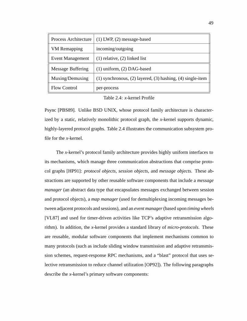
49
Process Architecture(1) LWP, (2) message-based
VM Remapping incoming/outgoing
Event Management (1) relative, (2) linked list
Message Buffering (1) uniform, (2) DAG-based
Muxing/Demuxing (1) synchronous, (2) layered, (3) hashing, (4) single-item
Flow Control per-process
Table 2.4:x-kernel Profile
Psync [PBS89]. Unlike BSD UNIX, whose protocol family architecture is character-
ized by a static, relatively monolithic protocol graph, thex-kernel supports dynamic,
highly-layered protocol graphs. Table 2.4 illustrates the communication subsystem pro-
file for thex-kernel.
Thex-kernel’s protocol family architecture provides highly uniform interfaces to
its mechanisms, which manage three communication abstractions that comprise proto-
col graphs [HP91]:protocol objects, session objects, andmessage objects. These ab-
stractions are supported by other reusable software components that include amessage
manager(an abstract data type that encapsulates messages exchanged between session
and protocol objects), amap manager(used for demultiplexing incoming messages be-
tween adjacent protocols and sessions), and anevent manager(based upontiming wheels
[VL87] and used for timer-driven activities like TCP’s adaptive retransmission algo-
rithm). In addition, thex-kernel provides a standard library ofmicro-protocols. These
are reusable, modular software components that implement mechanisms common to
many protocols (such as include sliding window transmission and adaptive retransmis-
sion schemes, request-response RPC mechanisms, and a “blast” protocol that uses se-
lective retransmission to reduce channel utilization [OP92]). The following paragraphs
describe thex-kernel’s primary software components:
50
� Protocol Objects: Protocol objects are software abstractions that represent network
protocols in thex-kernel. Protocol objects belong to one of two “realms,” either the
asynchronousrealm (e.g., TCP, IP, UDP) or thesynchronousrealm (e.g., RPC). The
x-kernel implements a protocol graph by combining one or more protocol objects. A
protocol object contains a standard set of subroutines that provide uniform interfaces
for two major services: (1) creating and destroying session objects (which maintain
a network connection’s context information) and (2) demultiplexing message objects
up to the appropriate higher-layer session objects. Thex-kernel uses its map manager
abstraction to implement efficient demultiplexing. The map manager associates external
identifiers (e.g.,TCP port numbers or IP addresses) with internal data structures (e.g.,
session control blocks). It is implemented as a chained-hashing scheme with a single-
item cache.
� Session Objects: A session object maintains context information associated with a
local end-point of a connection. For example, a session object stores the context infor-
mation for an active TCP state machine. Protocol objects create and destroy session ob-
jects dynamically. When an application opens multiple connections, one or more session
objects will be created within the appropriate protocol objects in a protocol graph. The
x-kernel supports operations on session objects that involve “layer-to-layer” activities
such as exchanging messages between higher-level and lower-level sessions. However,
thex-kernel’s protocol family architecture framework does not provide standard mech-
anisms for “end-to-end” session architecture activities such as connection management,
error detection, or end-to-end flow control. A related project, Avoca, builds upon the
basicx-kernel facilities to provide these end-to-end session services [OP92].
� Message Objects: Message objects encapsulate control and user data information
that flows “upwards” or “downwards” through a graph of session and protocol objects.
51
In order to decrease memory-to-memory copying and to implement message operations
efficiently, message objects are implemented using a “directed-acyclic-graph” (DAG)-
based data structure. This DAG-based scheme uses “lazy-evaluation” to avoid unnec-
essary data copying when passing messages between protocol layers [HMPT89]. It also
stores message headers in a separate “header stack” and uses pointer arithmetic on this
stack to reduce the cost of prepending or stripping message headers.
Thex-kernel employs a “process-per-message” message-based process architec-
ture that resides in either the OS kernel or in user-space. The kernel implementation
maintains a pool of light-weight processes (LWPs). When a message arrives at a net-
work interface, a separate LWP is dispatched from the pool to shepard the message
upwards through the graph of protocol and session objects. In general, only one context
switch is required to shepard a message through the protocol graph, regardless of the
number of intervening protocol layers. Thex-kernel also supports other context switch
optimizations that (1) allow user processes to transform into kernel processes via sys-
tem calls when sending message and (2) allow kernel processes to transform into user
processes via upcalls when receiving messages [Cla85].
2.4.1.4 The Conduit Framework
The Conduit framework provides the protocol family architecture, session archi-
tecture, and application interface for the Choices operating system [CRJ87]. Choices
was developed to investigate the suitability of object-oriented techniques for designing
and implementing OS kernel and networking mechanisms.4 For example, the design of
ZOOT (the Choices TCP/IP implementation) uses object-oriented language constructs
4Choices and the Conduit framework are written using C++. All the other surveyed systems are written
in C.

52
Process Architecture(1) LWP, (2) hybrid (process-per-buffer)
VM Remapping none
Event Management ND
Message Buffering (1) uniform, (2) list-based
Muxing/Demuxing (1) ND, (2) layered, (3) ND, (4) ND
Flow Control ND
Table 2.5: Conduit Profile
and design methods such as inheritance, dynamic binding, and delegation [ZJ91] to im-
plement the TCP state machine in a highly modular fashion. Together, Choices and the
Conduit framework provide a general-purpose communication subsystem. Table 2.5 il-
lustrates the communication subsystem profile for the Choices Conduit framework. In
the discussion below, the term “Conduit framework” refers to the overall communica-
tion subsystem, whereas a “Conduit ” corresponds to an abstract data type used to
construct and coordinate various network protocols.
The three major components in the Conduit framework are:Conduits , Conduit
Messages , andConduit Addresses . A Conduit is a bi-directional communica-
tion abstraction, similar to a System V STREAM module. It exports operations that al-
low Conduits (1) to link together and (2) to exchange messages with adjacently linked
Conduits . Conduit Messages are typed objects exchanged between adjacent
Conduits in a protocol graph.Conduit Addresses are utilized byConduits
to determine where to deliverConduit Messages . All three components are de-
scribed in the following paragraphs:
� The Conduit Base Class and Subclasses:A Conduit provides the basis for im-
plementing many types of network protocols including connectionless (e.g.,Ethernet,
53
IP, ICMP, and UDP), connection-oriented (e.g.,TCP and TP4), and request-response
(e.g.,RPC and NFS) protocols. It is represented as a C++ base class that provides two
types of operations that are inherited and/or redefined by derived subclasses. One type
of operation composes protocol graphs by connecting and disconnectingConduits
instances. The other type of operation inserts messages into the “top” and/or “bottom”
of aConduit . EachConduit has two ends for processing data and control messages:
the top end corresponds to messages flowingdownfrom an application; the bottom end
corresponds to messages flowingup from a network interface.
The Conduit framework uses C++ mechanisms such as inheritance and dynamic
binding to express the commonality between theConduit base class and its vari-
ous subclasses. These subclasses representspecializationsof abstract network pro-
tocol classes that provideVirtual Circuit and Datagramservices. For instance, the
Virtual Circuit Conduit andDatagram Conduit are standard Conduit frame-
work subclasses. Both subclasses export the “connect, disconnect, and message inser-
tion” mechanisms inherited from theConduit base class. In addition, they also extend
the base class interface by supplying operations that implement their particular mecha-
nisms. AVirtual Circuit Conduit provides an interface for managing end-to-
end “sliding window” flow control. It also specifies other properities associated with
virtual circuit protocols such as reliable, in-order, unduplicated data delivery. These
two subclasses are themselves used as base classes for further specializations such as
theTCP Conduit andEthernet Conduit subclasses, respectively.
� Conduit Messages: All messages that flow betweenConduits have a particular
type. This type indicates the contents of a message (e.g., its header and data format)

54
and specifies the operations that may be performed on the message. Messages are de-
rived from a C++ base class that provides the foundation for subsequent inherited sub-
classes. Different message subclasses are associated with the differentConduit sub-
classes that represent different network protocols. For example, theIP Message and
TCP Message subclasses correspond to theIP Conduits andTCP Conduits , re-
spectively.Conduit Message subclasses may also encapsulate other messages. For
instance, an IP message may contain a TCP, UDP, or ICMP message in its data portion.
� Conduit Addresses: Conduit Addresses indicate where to deliverConduit
Messages . The three main types ofConduit Addresses areexplicit, implicit, and
embedded. Explicit addresses identify entities that have a “well-known” format (such
as IP addresses). Implicit addresses, on the other hand, are “keys” that identify partic-
ular session control blocks associated with active network connections. For example, a
socket descriptor in BSD UNIX is an implicit address that references a session control
block. Finally, an embedded address is an explicit address that forms part of a mes-
sage header. For example, the fixed-length, 14 byte Ethernet headers are represented as
embedded addresses since passing a separate explicit address object is neither time nor
space efficient.
The Conduit framework is implemented in user-space and the relationship of pro-
cesses toConduits andConduit Messages is a hybrid between message-based
and task-based process architectures. Messages are escorted through the Conduit frame-
work protocol graph via “walker-processes,” which are similar to thex-kernel “process-
per-message” mechanism. Depending on certain conditions, a walker process escorts
outgoing messages most of the way up or down a protocol graph. However, when a
message crosses an address space boundary or must be stored in a buffer due to flow
control, it remains there until it is moved to an adjacentConduit . This movement

55
may result from either (1) a daemon process residing in theConduit that buffered the
message or (2) another process that knows how to retrieve the message from the flow
control buffer. In general, the number of processes required to escort a message through
the chain ofConduits corresponds to the number of flow control buffers between the
application and network interface layer.
2.4.2 Communication Subsystem Comparisons
This section compares and contrasts the four surveyed communication subsys-
tems using the taxonomy dimensions and alternatives presented in Table 2.1. Sec-
tion 2.4.2.1 focuses on the kernel architecture dimensions described in Section 2.3.1
and Section 2.4.2.2 focuses on the protocol family architecture dimensions described in
Section 2.3.2.
2.4.2.1 Comparison of Kernel Architecture Dimensions
� The Process Architecture Dimension: The surveyed communication subsystems
exhibit a range of process architectures. The conventional System V STREAMS im-
plementation uses a variant of the task-based process architecture known as a “process-
per-module” approach. However, as described in Section 2.4.1.1, the standard System
V STREAMS approach does not associate a heavy-weight OS process per module in
an effort to reduce context switching overhead and minimize kernel state information
required for process management.

56
The x-kernel and BSD UNIX utilize variants of a message-based process archi-
tecture. Thex-kernel supports highly-layered protocol graphs that use a “process-per-
message” approach that is tuned to avoid excessive context switching and IPC over-
head. BSD UNIX uses a message-based approach that behaves differently depending
on whether messages are flowing “up” or “down” through a protocol graph. For exam-
ple, BSD allows multiple processes into the kernel for outgoing messages, but permits
only one process to handle incoming messages.
The Conduit framework uses a “process-per-buffer” approach, which is a hybrid
between “process-per-message” and “process-per-module.” EachConduit containing
a flow control buffer may be associated with a separate light-weight process.
� The Virtual Memory Remapping Dimension: Recent versions ofx-kernel provide
virtual memory remapping [HMPT89] for transferring messages between application
process and the kernel. The Conduit framework, System V STREAMS and BSD UNIX,
on the other hand, do not generally provide this support.
� The Event Management Dimension: BSD UNIX stores pointers to subroutines
in a linked-list callout queue. These preregistered subroutines are called when a timer
expires. System V, on the other hand, maintains aheap-based callout table, rather than a
sorted list or array. The heap-based implementation outperforms the linked-list approach
under heavy loads [BL88]. Thex-kernel usestiming wheels[VL87] instead of callout
lists or heaps.

57
2.4.2.2 Comparison of Protocol Family Architecture Dimensions
Compared with the other surveyed communication subsystems, thex-kernel is
generally more comprehensive in supplying the interfaces and mechanisms for its pro-
tocol family architecture components. For example, it provides uniform interfaces for
operations that manage the protocol, session, and message objects comprising its highly-
layered protocol graphs. In addition, it also specifies mechanisms for event management
and multiplexing and demultiplexing activities. System V STREAMS specifies inter-
faces for the primary STREAM components, along with certain operations involving
layer-to-layer flow control. BSD UNIX and the Conduit framework, on the other hand,
do not systematically specify the session, demultiplexing, and flow control mechanisms
in their protocol family architecture.
� The Message Management Dimension: Both System V STREAMS messages and
BSD mbufs use a linear-list-based approach. In contrast, thex-kernel uses a DAG-based
approach that separates messages into “header stacks” and “data graphs.” Thex-kernel
uses this more complex DAG-based message manager to handle certain requirements of
highly-layered protocol graphs (such as minimizing the amount of memory-to-memory
copying between protocol layers).
� The Multiplexing and Demultiplexing Dimension: The four surveyed communi-
cation subsystems possess a wide range of multiplexing and demultiplexing strategies.
The x-kernel provides the most systematic support for these operations. It provides a
map managerthat uses a hash table mechanism with a single-item cache. The other
communication subsystems provide less systematic and non-uniform mechanisms.
In particular, System V STREAMS and the Conduit framework do not define a
standard multiplexing and demultiplexing interface. Moreover, for outgoing messages,

58
the Conduit framework involves an extra multiplexing operation compared to thex-
kernel scheme. In thex-kernel, a single operation transfers outgoing messages from a
higher-layer session object down to lower-layer session object. AConduit , on the
other hand, requires two operations to send a message: (1) it locates the appropriate
session connection descriptor associated with the lower-levelConduit and (2) then
passes the message down to that associatedConduit .
The BSD UNIX multiplexing and demultiplexing mechanisms differ depending
on which protocol component and protocol family are involved. For instance, its IP
implementation uses the 8-bit IP message type-of-service field to index into an array
containing 256 entries that correspond to higher-layer protocol control structures. On
the other hand, its TCP implementation uses sequential search with a one-item cache to
demultiplex incoming messages to the appropriate connection session. As described in
Section 2.3.2.2, this implementation is inefficient when application data arrival patterns
do not form message-trains [MD91].
� The Layer-to-Layer Flow Control Dimension: With the exception of System V
STREAMS, the surveyed communication subsystems do not provide uniform layer-
to-layer flow control mechanisms. Each STREAM module contains high- and low-
watermarks that manage flow control between adjacent modules. Downstream flow
control operates from the “bottom up.” If all STREAM modules on a Stream cooperate,
it is possible to control the amount and the rate of messages by exerting “back-pressure”
up a stack of STREAM modules to a user process. For example, if the network becomes
too congested to accept new messages (or if messages are being sent by a process faster
than they are transmitted), STREAM driver queues fill up first. If messages continue
flowing from upstream modules, the first module above the driver that has aservice

59
subroutine will fill up next. This back-pressure potentially propagates all the way up to
the STREAM head, which then blocks the user process.
In BSD UNIX, flow control occurs at several locations in the protocol family ar-
chitecture. The socket level flow control mechanism uses the high- and low-watermarks
stored in the socket data structure. If a process tries tosend more data than is allowed
by a socket’s highwater mark, the BSD kernel puts the process to sleep. Unlike System
V, however, BSD UNIX has no standard mechanism for applying back-pressure between
protocol components such as TCP and IP. At the network interface layer, queues are used
to buffer messages between the network adapters and the lowest-level protocol (e.g.,IP,
IDP, or CLNP). The queues have a maximum length that serves as a simple form of flow
control. Subsequent incoming messages are dropped if these queues become full.
Thex-kernel and the Conduit framework provide less systematic flow control sup-
port. Thex-kernel uses a coarse-grained, per-process flow control by discarding incom-
ing messages if there are no light-weight processes available to shepard them up the
protocol graph. The Conduit framework does not provide a standard mechanism to
manage flow control between modules in a given stack ofConduits . EachConduit
passes a message up or down to its neighbor. If the neighbor is unable to accept the mes-
sage, the operation either blocks or returns an error code (in which case the caller may
either discard the message or retain it for subsequent retransmission). This approach
allows eachConduit to determine whether it is a “message-discarding” entity or a
“patiently-blocking” entity.
60
2.5 Summary
This chapter examines the major levels of software mechanisms in the commu-
nication subsystem architecture. A taxonomy of six communication subsystem mecha-
nisms is presented and used to compare different design alternatives found in four exist-
ing commercial and experimental operating systems. Based upon our experience with
communication subsystems, combined with our survey of research literature and exist-
ing systems, we view the following as important open research issues pertinent to the
development of communication subsystem architectures:
� Which communication subsystem levels (e.g., application interface, session ar-
chitecture, protocol family architecture, kernel architecture) incur the most com-
munication performance overhead?
� Which choices from among the taxonomy dimensions and alternatives improve
the overall communication performance? For example, which process architec-
tures result in the highest performance? Likewise, what combinations of applica-
tion requirements and network characteristics are most suitable for different com-
munication subsystem profiles?
� How will the performance bottlenecks shift as the boundary between hardware
and software changes? For instance, the high cost of message management oper-
ations such as fragmentation and reassembly may be greatly reduced if they are
performed in hardware, as proposed for ATM.
� Which communication subsystem profiles are best suited for multimedia applica-
tions running in high-performance network environments? Moreover, what are
the appropriate design strategies and implementation techniques required to pro-
vide integratedsupport for multimedia applications that run on general-purpose
workstation operating systems?

61
This chapter attempts to clarify the essential issues and relationships that arise when de-
veloping high-performance communication subsystem architectures. Subsequent chap-
ters discuss performance experiments conducted using an object-oriented framework
called the ADAPTIVE Service eXecutive (ASX). TheASXframework supports experi-
mentation with different process architectures for parallelizing high-performance com-
munication subsystem.
Chapter 3
The ADAPTIVE Service eXecutive
Framework
3.1 Introduction
Developing extensible, robust, and efficient distributed communication systems is
a complex task. To help alleviate this complexity, we have developed the ADAPTIVE
Service eXecutive (ASX) framework.ASX is an object-oriented framework composed
of automated tools and reusable components that simplify the development, configu-
ration, and reconfiguration, and testing protocol stacks within communication subsys-
tems. TheASX framework has also been used to develop distributed applications in a
heterogeneous environment [SS94b, SS94a]. These applications may be configured to
contain multiple network services that execute concurrently in one or more processes or
threads. Furthermore, the services in these applications may be updated and extended
without modifying, recompiling, relinking, or restarting the applications at run-time.
This chapter describes the object-oriented architecture of theASXframework.
62

63
3.2 Object-Oriented Frameworks
Object-oriented frameworks help to alleviate the complexity associated with de-
veloping, configuring, and reconfiguring distributed application services. A framework
is an integrated collection of software components that collaborate to produce a reusable
architecture for a family of related applications [JF88]. Object-oriented frameworks are
becoming increasingly popular as a means to simplify and automate the development
and configuration of complex applications in domains such as graphical user interfaces
[LC87, WGM88], databases [BO92], operating system kernels [CRJ87], and communi-
cation subsystems [Zwe90, SS94c].
The components in a framework typically includeclasses(such as message man-
agers and timer-based event managers, and connection maps [HP91]),class hierarchies
(such as an inheritance lattice of mechanisms for local and remote interprocess com-
munication [Sch92]),class categories(such as a family of concurrency mechanisms
[SS94c]), andobjects(such as an event demultiplexer [Sch95]).
As shown in Figure 3.1, frameworks are distinguished from conventional class
libraries in the following ways:
� The components constituting a framework are integrated together to address a par-
ticular problem domain [Sch94a]. In contrast, class library components are often
developed to be domain independent. Domain-independent components include
class libraries containing mathematical functions and abstract data type compo-
nents (such as classes for complex numbers, arrays, bitsets, etc.).
� Complete communication systems may be formed by inheriting from and/or cus-
tomizing existing framework components, rather than invoking methods on ob-
jects provided in a class library. Inheritance enables the features of a framework
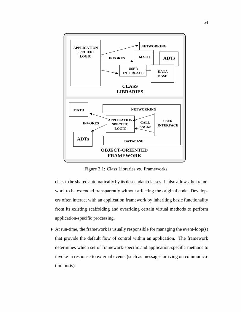
64
APPLICATIONSPECIFIC
LOGIC
USERINTERFACE
CLASSLIBRARIES
NETWORKING
MATH ADTS
DATABASE
APPLICATIONSPECIFIC
LOGIC
MATH
OBJECT-ORIENTEDFRAMEWORK
ADTS
INVOKES
CALLBACKS
NETWORKING
USERINTERFACE
DATABASE
INVOKES
Figure 3.1: Class Libraries vs. Frameworks
class to be shared automatically by its descendant classes. It also allows the frame-
work to be extended transparently without affecting the original code. Develop-
ers often interact with an application framework by inheriting basic functionality
from its existing scaffolding and overriding certain virtual methods to perform
application-specific processing.
� At run-time, the framework is usually responsible for managing the event-loop(s)
that provide the default flow of control within an application. The framework
determines which set of framework-specific and application-specific methods to
invoke in response to external events (such as messages arriving on communica-
tion ports).
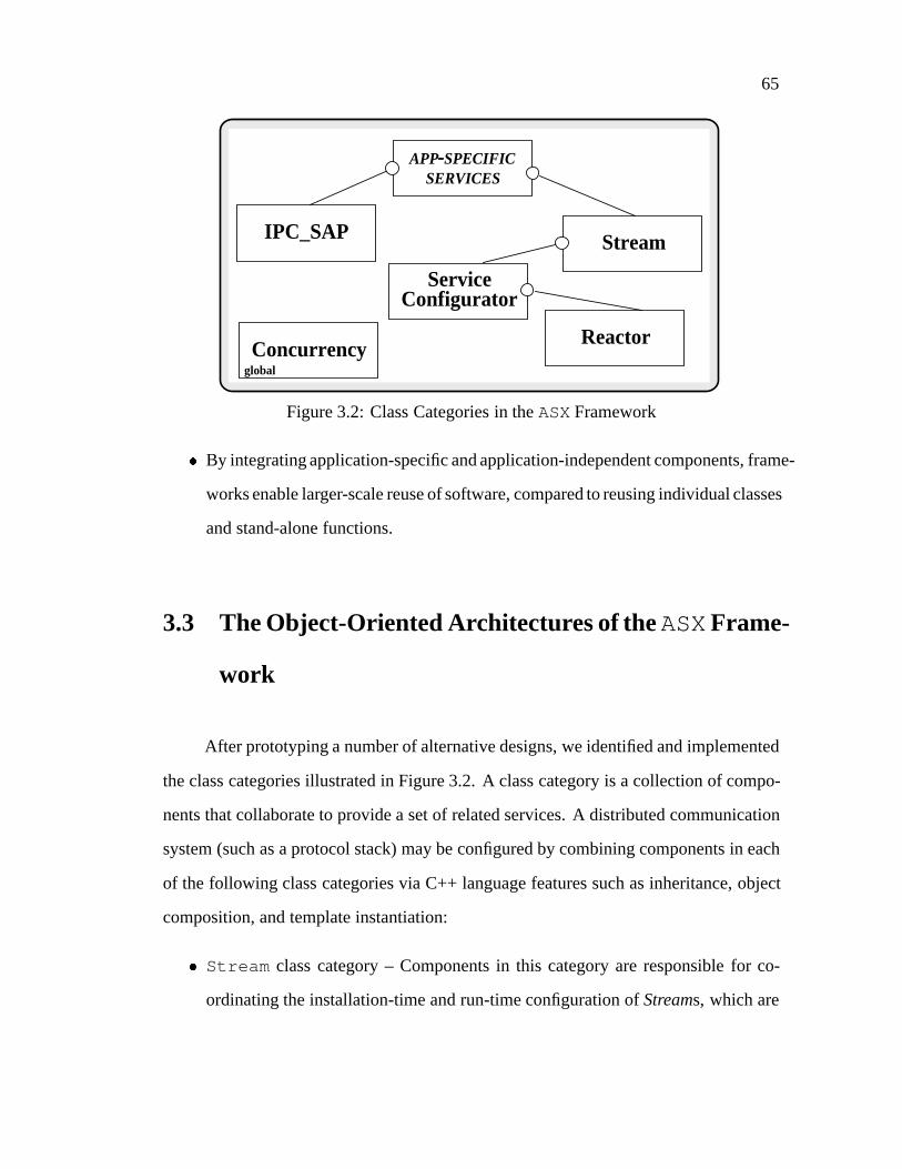
65
Stream
ServiceConfigurator
Reactor
APP-SPECIFICSERVICES
Concurrencyglobal
IPC_SAP
Figure 3.2: Class Categories in theASXFramework
� By integrating application-specific and application-independent components, frame-
works enable larger-scale reuse of software, compared to reusing individual classes
and stand-alone functions.
3.3 The Object-Oriented Architectures of theASXFrame-
work
After prototyping a number of alternative designs, we identified and implemented
the class categories illustrated in Figure 3.2. A class category is a collection of compo-
nents that collaborate to provide a set of related services. A distributed communication
system (such as a protocol stack) may be configured by combining components in each
of the following class categories via C++ language features such as inheritance, object
composition, and template instantiation:
� Stream class category – Components in this category are responsible for co-
ordinating the installation-time and run-time configuration ofStreams, which are
66
collections of hierarchically-related protocol tasks that are composed to form com-
munication protocol stacks [SS95a].
� The Reactor class category – These components are responsible fordemulti-
plexingtemporal events generated by a timer-driven callout queue, I/O events re-
ceived on communication ports, and signal-based events [Sch95, Sch93b, Sch93a].
TheReactor alsodispatchesthe appropriate pre-registered handler(s) to process
these events.
� TheService Configurator class category – These components are respon-
sible fordynamically linkingor dynamically unlinkingservices into or out of the
address space of an application at run-time [SS94d, SS94a].
� TheConcurrency class category – These components are responsible forspawn-
ing, executing, synchronizing, andgracefully terminatingservices at run-time via
one or more threads of control within one or more processes [Sch94b].
� TheIPC SAPclass category – These components encapsulate standard OS local
and remote IPC mechanisms (such as sockets and TLI) within a type-safe and
portable object-oriented interface [Sch92].
Lines connecting the class categories in Figure 3.2 indicate dependency relationships.
For example, components that implement the application-specific services in a particular
distributed application depend on theStream components, which in turn depend on the
Service Configurator components. Since components in theConcurrency
class category are used throughout the application-specific and application-independent
portions of theASXframework they are marked with theglobal adornment.
TheASXframework helps control for several confounding factors such as proto-
col functionality, concurrency control strategies, application traffic characteristics, and
network interfaces. This enables precise measurement of the performance impact from

67
using different process architectures to parallelize protocol stacks in a multi-processor
platform. In the experiments described in Chapter 4, theASXframework is used to hold
protocol functionality constant, while allowing the process architecture to be systemat-
ically altered in a controlled manner.
TheASXframework incorporates concepts from several existing communication
frameworks such as System V STREAMS [Rit84], thex-kernel [HP91], and the Conduit
[Zwe90]. These frameworks contain tools that support the flexible configuration of com-
munication subsystems. These tools support the interconnection of building-block pro-
tocol components (such as message managers, timer-based event dispatchers, and con-
nection demultiplexers [HP91] and other reusable protocol mechanisms [SSS+93]) to
form protocol stacks. In addition to supplying building-block protocol components, the
ASX framework also extends the features provided by existing communication frame-
works. In particular,ASXprovides components that decouple protocol-specific func-
tionality from the following structural and behavioral characteristics of a communication
subsystem:
� The type of locking mechanisms used to synchronize access to shared objects
� The use of message-based and task-based process architectures
� The use of kernel-level vs. user-level execution agents
TheseASXframework components simplify development of and experimentation with
protocol stacks that are functionally equivalent, but possess significantly different pro-
cess architectures.
The remainder of this section describes the main components in each of theASX
framework’s class categories. Throughout the dissertation, components in theASX
framework are illustrated with Booch notation [Boo93]. Solid clouds indicate objects;

68
NETWORK INTERFACE
OR PSEUDO-DEVICES
STREAMTail
Multiplexor
APPLICATION
STREAMHead
APPLICATION
UP
STR
EA
MDO
WN
STR
EA
M
MESSAGE
OBJECT
WRITEQUEUEOBJECT
READQUEUEOBJECT
MODULE
OBJECT
open()=0close()=0put()=0svc()=0
Figure 3.3: Components in theStream Class Category
nesting indicates composition relationships between objects; and undirected edges indi-
cate a link exists between two objects. Dashed clouds indicate classes; directed edges
indicate inheritance relationships between classes; and an undirected edge with a small
circle at one end indicates either a composition or a uses relation between two classes.
Solid rectangles indicate class categories, which combine a number of related classes
into a common name space.
3.3.1 TheStream Class Category
Components in theStream class category are responsible for coordinating the
installation-time and/or run-time configuration of one or more Streams. A Stream is an
object that applications communicate with at run-time to configure and execute protocol

69
stacks in theASX framework. As illustrated in Figure 3.3, a Stream contains a series
of interconnectedModule objects.Module objects are used to decompose a protocol
stack into a functionally distinct levels. Each level implements a cluster of related pro-
tocol tasks (such as an end-to-end transport service or a presentation layer formatting
service).
Any level that requires multiplexing and/or demultiplexing of messages between
one or more related Streams may be developed using aMultiplexor object. A
Multiplexor is a container object that provides mechanisms that route messages be-
tweenModules in a collection of related Streams. BothModule andMultiplexor
objects may be flexibly configured into a Stream by developers at installation-time, as
well as by applications at run-time.
Every Module contains a pair ofQueue objects that partition a level into the
read-side and write-side functionality required to implement a particular protocol task.
A Queue provides an abstract domain class that may be specialized to target a specific
domain (such as the domain of communication protocol stacks or the domain of net-
work management applications [SS94b]). EachQueue contains aMessage List ,
which is a reusableASXframework component that queues a sequence of data messages
and control messages for subsequent processing. Protocol tasks in adjacentModules
communicate by exchanging typed messages via a uniform message passing interface
defined by theQueue class.
TheASXframework employs a variety of design techniques (such as object-oriented
design patterns [Sch95, GHJV94] and hierarchical software decomposition [BO92]) and
C++ language features (such as inheritance, dynamic binding, and parameterized types
[Bja91]). These design techniques and language features enable developers to flexibly
configure protocol-specific functionality into a Stream without modifying the reusable
70
protocol-independent framework components. For example, incorporating a new level
of protocol functionality into a Stream at installation-time or at run-time involves the
following steps:
1. Inheriting from theQueue class interface and selectively overriding several meth-
ods (described below) in the newQueue subclass to implement protocol-specific
functionality
2. Allocating a newModule that contains two instances (one for the read-side and
one for the write-side) of the protocol-specificQueue subclass
3. Inserting theModule into a Stream object at the appropriate level (e.g.,the trans-
port layer, network layer, data-link layer, etc.)
To avoid reinventing terminology, many component names in theStream class
category correspond to similar componentry available in the System V STREAMS frame-
work [Rit84]. However, the techniques used to support extensibility and concurrency in
the two frameworks differ significantly. As describe above, incorporating new protocol-
specific functionality to anASXStream is performed by inheriting interfaces and im-
plementations from existingASX framework components. Using inheritance to add
protocol-specific functionality provides greater type-safety compared with the pointer-
to-function techniques used in System V STREAMS. In addition, theASX Stream
classes also redesign and reimplement the co-routine-based, “weightless”1 service pro-
cessing mechanisms used in System V STREAMS. TheseASX changes enable more
effective use of multiple PEs on a shared memory multi-processing platform by reduc-
ing the opportunities for deadlock and simplifying flow control betweenQueues in a
Stream. The remainder of this section discusses the primary components of theASX
1A weightless process executes on a run-time stack that is also used by other processes. This compli-
cates programming and increases the potential for deadlock since a weightless process may not suspend
execution to wait for resources to become available or for events to occur [SPY+93].
71
Stream class category: theStream class, theModule class, theQueue class, and
theMultiplexor class.
3.3.1.1 The STREAM Class
TheSTREAMclass defines the application interface to a Stream. ASTREAMob-
ject provides a bi-directionalget /put -style interface that allows applications to access
a protocol stack containing a series of interconnectedModules . Applications send
and receive data and control messages through the stack ofModules that comprise a
STREAMobject. In addition, theSTREAMclass implements apush /pop -style interface
that enables applications to configure a Stream at run-time by inserting and removing
protocol-specificModule class objects.
3.3.1.2 The Module Class
TheModule class defines a distinct level of protocol functionality in a protocol
stack. A Stream is formed incrementally by connecting eachModule object in the
Stream with two adjacentModule objects (one “upstream” and one “downstream”).
EachModule contains a pair of objects that inherit from theQueue class described
in Section 3.3.1.3 below. AModule uses its twoQueue subclass objects to imple-
ment its bi-directional, protocol-specific functionality. AModule communicates with
its neighboringModule objects by passing typed messages. Message passing overhead
is minimized by passing a pointer to a message between twoModules , rather than by
copying the data.

72
The Stream Head andStream Tail Module objects shown in Figure 3.3
are installed automatically when a Stream is first opened. These twoModules inter-
pret pre-definedASXframework control messages and data messages that pass through
a Stream at run-time. In addition, theStream Head Module provides a synchronous
message queueing interface between an application and a Stream. The read-side of a
Stream Tail Module transforms incoming messages from a network interface (or
from a pseudo-interface such as a loop-back device) into a canonical internal Stream
message format. These messages are subsequently processed by higher-level compo-
nents in a Stream and subsequently delivered to an application. The write-side of a
Stream Tail Module transforms outgoing messages from their internal Stream for-
mat into the appropriate network message format and passes the message to a network
interface.
3.3.1.3 The Queue Abstract Class
The Queue abstract class2 defines an interface that subclasses inherit and se-
lectively override to provide the read-side and write-side protocol functionality in a
Module . TheQueue class is an abstract class since its interface defines the four pure
virtual methods (open , close , put , andsvc ) described below. By definingQueue as
an abstract class, the protocol-independent components (such as message objects, mes-
sage lists, and message demultiplexing mechanisms) provided by theStream class cat-
egory are decoupled from the protocol-specific subclasses (such as those implementing
the data-link, IP, TCP, UDP, and XDR protocols) that inherit and use these components.
2An abstract class in C++ provides an interface that contains at least onepure virtual method[Bja90].
A pure virtual method provides only an interface declaration, without supplying any accompanying def-
inition for the method. Subclasses of an abstract class must provide definitions for all its pure virtual
methods before any objects of the subclass may be instantiated.
73
This decoupling enhances component reuse and simplifies protocol stack development
and configuration.
The open andclose methods in theQueue class may be specialized via in-
heritance to perform activities that are necessary to initialize and terminate a protocol-
specific object, respectively. These activities allocate and deallocate resources such as
connection control blocks, I/O descriptors, and synchronization locks. When aModule
is inserted or removed from a Stream, theASX framework automatically invokes the
open or close method of theModule ’s write-side and read-sideQueue subclass
objects.
The put method in aQueue is invoked by aQueue in an adjacentModule
passing it a message. Theput method runssynchronouslywith respect to its caller by
borrowing the thread of control from theQueue that invoked itsput method. This
thread of control typically originates either upstream from an application, downstream
from process(es) that handle network interface device interrupts, or internal to a Stream
from an event dispatching mechanism (such as a timer-driven callout queue [BL88] used
to trigger retransmissions in a connection-oriented transport protocol).
Thesvc method in aQueue may be specialized to perform protocol-specific pro-
cessingasynchronouslywith respect to otherQueues in its Stream. Asvc method
is not directly invoked from an adjacentQueue. Instead, it is invoked by a sepa-
rate process associated with theQueue. This process provides a separate thread of
control that executes theQueue’s svc method. This method runs an event loop that
waits continuously for messages to be inserted into theQueue’s Message List . A
Message List is a standard component in aQueue. Protocol-specific code may
reuse theMessage List to queue data messages and control messages for subse-
quent protocol processing. When messages are inserted into aMessage List , the
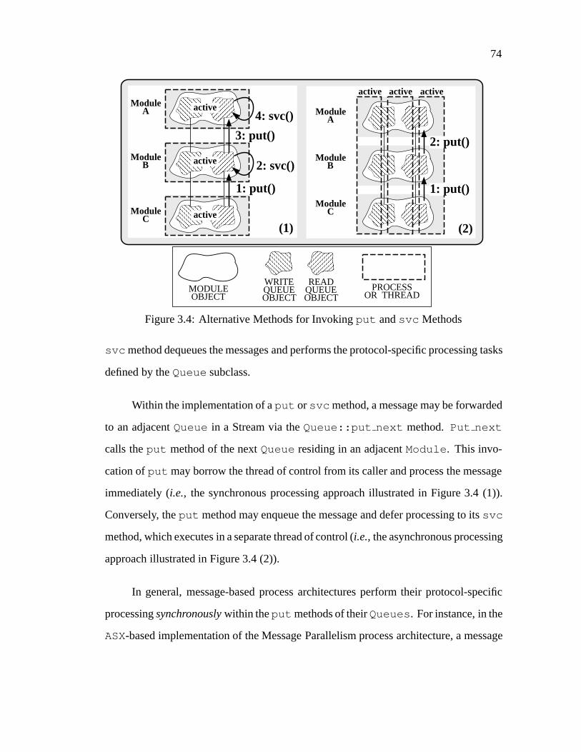
74
ModuleA
PROCESSOR THREAD
WRITEQUEUEOBJECT
READQUEUEOBJECT
MODULEOBJECT
ModuleB
ModuleC
ModuleA
ModuleB
ModuleC
2: svc()
1: put()
4: svc()
3: put()
active
active
active
active
2: put()
1: put()
activeactive
(1) (2)
Figure 3.4: Alternative Methods for Invokingput andsvc Methods
svc method dequeues the messages and performs the protocol-specific processing tasks
defined by theQueue subclass.
Within the implementation of aput or svc method, a message may be forwarded
to an adjacentQueue in a Stream via theQueue::put next method. Put next
calls theput method of the nextQueue residing in an adjacentModule . This invo-
cation ofput may borrow the thread of control from its caller and process the message
immediately (i.e., the synchronous processing approach illustrated in Figure 3.4 (1)).
Conversely, theput method may enqueue the message and defer processing to itssvc
method, which executes in a separate thread of control (i.e.,the asynchronous processing
approach illustrated in Figure 3.4 (2)).
In general, message-based process architectures perform their protocol-specific
processingsynchronouslywithin theput methods of theirQueues . For instance, in the
ASX-based implementation of the Message Parallelism process architecture, a message
75
arriving at a network interface is associated with a separate thread of control. This thread
of control is obtained from a pool of pre-initialized processes (which are labeled as the
active objects in Figure 3.4 (1)). The incoming message is escorted through a series of
interconnectedQueues in a Stream. A synchronous upcall [Cla85] to theput method
in an adjacentQueue is performed to pass a message to each higher level in a protocol
stack.
Task-based process architectures perform their processingasynchronouslyin the
svc methods of theirQueues , which execute in separate threads of control. For in-
stance, each protocol layer in theASX-based Layer Parallelism process architecture is
implemented in a separateModule object, which is associated with a separate process.
Messages arriving from a network interface are passed betweenQueues running in
the separate processes (which are labeled as the active objects in Figure 3.4 (2)). Each
Queue in a Stream asynchronously executes its protocol-specific tasks within itssvc
method. Chapter 4 illustrates the performance impact of using synchronous vs. asyn-
chronous processing to parallelize communication protocol stacks on a shared memory
multi-processor platform.
3.3.1.4 The Multiplexor Class
A Multiplexor routes messages between different Streams that implement lay-
ered protocol stacks. Although layered multiplexing and demultiplexing is generally dis-
paraged for high-performance communication subsystems [Fel90], most conventional
communication models (such as the Internet model or the ISO/OSI reference model) re-
quire some form of multiplexing. Thus, theASXframework provides mechanisms that
support it.
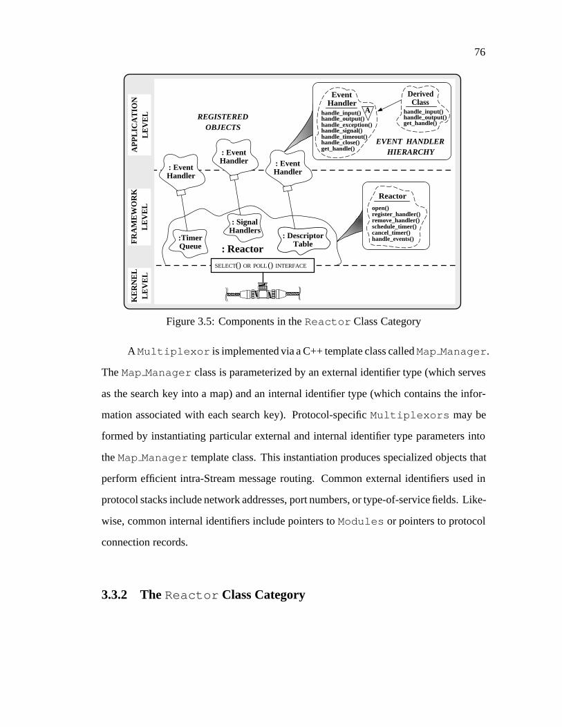
76
: Reactor
: EventHandler
: DescriptorTable
REGISTEREDOBJECTS
FR
AM
EW
OR
KL
EV
EL
KE
RN
EL
LE
VE
LA
PP
LIC
AT
ION
LE
VE
L
SELECT() OR POLL () INTERFACE
: EventHandler
:TimerQueue
open() register_handler() remove_handler() schedule_timer() cancel_timer() handle_events()
Reactor
EventHandler
Ahandle_input()handle_output()handle_exception()handle_signal()handle_timeout()handle_close()get_handle()
DerivedClass
handle_input()handle_output()get_handle()
EVENT HANDLERHIERARCHY: Event
Handler
: SignalHandlers
Figure 3.5: Components in theReactor Class Category
A Multiplexor is implemented via a C++ template class calledMap Manager .
TheMap Manager class is parameterized by an external identifier type (which serves
as the search key into a map) and an internal identifier type (which contains the infor-
mation associated with each search key). Protocol-specificMultiplexors may be
formed by instantiating particular external and internal identifier type parameters into
theMap Manager template class. This instantiation produces specialized objects that
perform efficient intra-Stream message routing. Common external identifiers used in
protocol stacks include network addresses, port numbers, or type-of-service fields. Like-
wise, common internal identifiers include pointers toModules or pointers to protocol
connection records.
3.3.2 TheReactor Class Category

77
Components in theReactor class category [Sch95, Sch93b, Sch93a] are respon-
sible for demultiplexing I/O-based events received on communication ports, time-based
events generated by a timer-driven callout queue, or signal-based events. When these
events occur at run-time, theReactor dispatches the appropriate pre-registered han-
dler(s) to process the events. TheReactor encapsulates and enhances the functionality
of OS event demultiplexing mechanisms (such as the UNIXselect andpoll sys-
tem calls or the Windows NTWaitForMultipleObjects system call). These OS
mechanisms detect the occurrence of different types of input and output events on one
or more I/O descriptors simultaneously.
TheReactor contains the methods illustrated in Figure 3.5. These methods pro-
vide a uniform interface to manage objects that implement various types of application-
specific handlers. Certain methods register, dispatch, and remove I/O descriptor-based
and signal-based handler objects from theReactor . Other methods schedule, cancel,
and dispatch timer-based handler objects. As shown in Figure 3.5, these handler ob-
jects all derive from theEvent Handler abstract base class. This class specifies an
interface for event registration and service handler dispatching.
TheReactor uses the virtual methods defined in theEvent Handler inter-
face to demultiplex I/O descriptor-based, timer-based, and signal-based events. When
these events occur at run-time, theReactor dispatches the appropriate pre-registered
handler(s) to process the events. I/O descriptor-based events are dispatched via the
handle input , handle output , andhandle exception methods; timer-based
events are dispatched via thehandle timeout method; and Signal-based events are
dispatched via thehandle signal method. Subclasses ofEvent Handler may
augment the base class interface by defining additional methods and data members. In
addition, virtual methods in theEvent Handler interface may be selectively overrid-
den to implement application-specific functionality. Once the pure virtual methods in

78
1
1
1
1
ServiceConfig
svc_conf_file open() process_directives() load_service() unload_service() resume_service() suspend_service() run_event_loop() daemonize()
REACTOR
nEvent
Handler
ServiceRepository
1
n
ServiceObject
(2) The Service_RepositoryClass
(3) The Service_ConfigClass
open()insert()find()remove ()resume()suspend()
ServiceRepository
open()reset()getnext()advance()
ServiceRepository
Iterator
F
1
n
1
1
open() register_handler() remove_handler() schedule_timer() cancel_timer() handle_events()
1
ServiceObject
A
suspend()resume()
(1) Service_ObjectInheritance Hierarchy
Queueopen()=0close()=0put()=0service()=0
EventHandler
handle_input()handle_output()handle_exception()handle_signal()handle_timeout ()handle_close()get_handle()A
SharedObject
init()=0fini ()=0info()=0
A
ServiceObject
QUEUE
QUEUE
A
Figure 3.6: Components in theService Configurator Class Category
theEvent Handler base class have been supplied by a subclass, an application may
define an instance of the resulting composite service handler object.
When an application instantiates and registers a composite I/O descriptor-based
service handler object, theReactor extracts the underlying I/O descriptor from the
object. This descriptor is stored in a table along with I/O descriptors from other reg-
istered objects. Subsequently, when the application invokes its main event loop, these
descriptors are passed as arguments to the underlying OS event demultiplexing system
call (e.g.,select , poll , or WaitForMultipleObjects ). As events associated
with a registered handler object occur at run-time, theReactor automatically detects
these events and dispatches the appropriate method(s) of the service handler object as-
sociated with the event. This handler object then becomes responsible for performing its
application-specific functionality before returning control to the mainReactor event-
loop.

79
3.3.3 TheService Configurator Class Category
Components in theService Configurator class category are responsible
for dynamically linking or unlinking protocol tasks into or out of the address space
of a communication subsystem at run-time. Dynamic linking enables the configura-
tion and reconfiguration of protocol-specific serviceswithout requiring the modifica-
tion, recompilation, relinking, or restarting of an executing system. TheService
Configurator components discussed below include the theService Object in-
heritance hierarchy (Figure 3.6 (1)), theService Repository class (Figure 3.6 (2)),
and theService Config class (Figure 3.6 (3)). This discussion focuses on using the
Service Configurator class category in the context of configuring application-
tailored protocol stacks [SSS+93]. However, these components are also useful in other
domains such as network management [SS94b] and configurable distributed systems
[SS94a].
3.3.3.1 The ServiceObject Inheritance Hierarchy
TheService Object class is the focal point of a multi-level hierarchy of types
related by inheritance. The interfaces provided by the abstract classes in this type hi-
erarchy may be selectively implemented by application-specific subclasses to access
Service Configurator features. These features provide transparent dynamic
linking, service handler registration, event demultiplexing, service dispatching, and ser-
vice run-time control (such as suspending and resuming a service temporarily). By de-
coupling the application-specific portions of a handler from the underlyingService
Configurator mechanisms, the effort necessary to insert and remove services from
an application at run-time is reduced significantly.
80
TheService Object inheritance hierarchy consists of theEvent Handler
andShared Object abstract base classes, as well as theService Object abstract
derived class. TheEvent Handler class was described above in theReactor Sec-
tion 3.3.2. The behavior of the other classes in theService Configurator class
category is outlined below:
�The SharedObject Abstract Base Class: This abstract base class specifies an inter-
face for dynamically linking and unlinking objects into and out of the address space of an
application. This abstract base class exports three pure virtual methods:init , fini ,
andinfo . These methods impose a compiler-enforced contract between the reusable,
service-independent components provided by theService Configurator and
application-specific objects that utilize these components. The use of pure virtual meth-
ods enables theService Configurator to ensure that a service handler implemen-
tation honors its obligation to provide certain configuration-related information. This
information is subsequently used by theService Configurator to automatically
link, initialize, identify, and unlink a service at run-time.
The init method serves as the entry-point to an object during run-time initial-
ization. This method performs application-specific initialization when an object derived
from Shared Object is dynamically linked. Theinfo method returns a humanly-
readable string that concisely reports service addressing information and documents ser-
vice functionality. Clients may query an application to retrieve this information and use
it to contact a particular service running in the application. Thefini method is called
automatically by theService Configurator class category when an object is un-
linked and removed from an application at run-time. This method typically performs
termination operations that release dynamically allocated resources (such as memory or
synchronization locks).

81
TheShared Object class is defined independently from theEvent Handler
class to clearly separate their two orthogonal sets of concerns. For example, certain ap-
plications (such as a compiler or text editor) might benefit from dynamic linking, though
they might not require I/O descriptor-based, timer-based, signal-based event demulti-
plexing. Conversely, other applications (such as anftp server) require event demulti-
plexing, but might not require dynamic linking.
� The ServiceObject Abstract Derived Class: Support for dynamic linking, event
demultiplexing, and service dispatching is necessary to automate the dynamic configura-
tion and reconfiguration of application-specific services in a distributed system. There-
fore, theService Configurator class category provides theService Object
class, which combines the interfaces inherited from both theEvent Handler and
theShared Object abstract base classes. During development, application-specific
subclasses ofService Object may implement thesuspend andresume virtual
methods in this class. Thesuspend andresume methods are invoked automatically
by theService Configurator class category in response to certain external events
(such as those triggered by receipt of the UNIX SIGHUP signal). An application devel-
oper may define these methods to perform actions necessary to suspend a service object
without unlinking it completely, as well as to resume a previously suspended service
object. In addition, application-specific subclasses must implement the four pure virtual
methods (init , fini , info , andget handle ) that are inherited (but not defined)
by theService Object subclass.
Note that theQueue class in theStream class category (described in Section 3.3.1)
is derived from theService Object inheritance hierarchy (illustrated in Figure 3.6 (1)).
This enables hierarchically-related, application-specificQueues (which are grouped

82
together to form theModules comprising an application Stream) to be linked and un-
linked into and out of an application at run-time.
3.3.3.2 The ServiceRepository Class
TheASXframework supports the configuration of applications that contain one or
more Streams, each of which may have one or more interconnected application-specific
Modules . Therefore, to simplify run-time administration, it may be necessary to indi-
vidually and/or collectively control and coordinate theService Objects that com-
prise an application’s currently active Streams. TheService Repository is an
object manager that theASXframework uses to coordinate local/remote queries and up-
dates regarding the services offered by Streams in an application. A search structure
within the object manager binds service names (represented as a string) with instances
of compositeService Objects (represented as C++ object code). A service name
uniquely identifies an instance of aService Object stored in the repository.
EachService Repository entry contains a pointer to theService Object
portion of an application-specific subclass (shown in Figure 3.6 (2)). This enables the
Service Configurator classes to automatically load, enable, suspend, resume, or
unloadService Objects from a Stream dynamically. The repository also maintains
a handle to the shared object file for each dynamically linkedService Object . This
handle is used to unlink and unload aService Object from a running application
when its service is no longer required. An iterator class is also supplied along with the
Service Repository . This class may be used to visit everyService Object
in the repository without compromising data encapsulation.
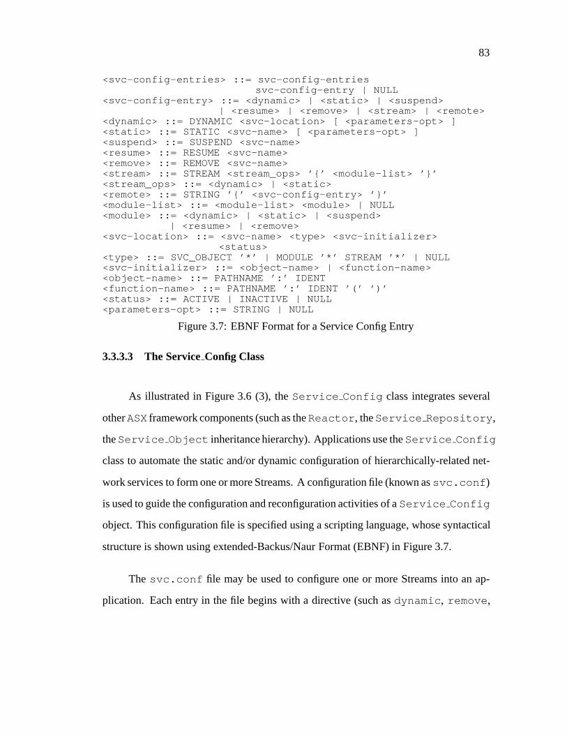
83
<svc-config-entries> ::= svc-config-entriessvc-config-entry | NULL
<svc-config-entry> ::= <dynamic> | <static> | <suspend>| <resume> | <remove> | <stream> | <remote>
<dynamic> ::= DYNAMIC <svc-location> [ <parameters-opt> ]<static> ::= STATIC <svc-name> [ <parameters-opt> ]<suspend> ::= SUSPEND <svc-name><resume> ::= RESUME <svc-name><remove> ::= REMOVE <svc-name><stream> ::= STREAM <stream_ops> ’{’ <module-list> ’}’<stream_ops> ::= <dynamic> | <static><remote> ::= STRING ’{’ <svc-config-entry> ’}’<module-list> ::= <module-list> <module> | NULL<module> ::= <dynamic> | <static> | <suspend>
| <resume> | <remove><svc-location> ::= <svc-name> <type> <svc-initializer>
<status><type> ::= SVC_OBJECT ’*’ | MODULE ’*’ STREAM ’*’ | NULL<svc-initializer> ::= <object-name> | <function-name><object-name> ::= PATHNAME ’:’ IDENT<function-name> ::= PATHNAME ’:’ IDENT ’(’ ’)’<status> ::= ACTIVE | INACTIVE | NULL<parameters-opt> ::= STRING | NULL
Figure 3.7: EBNF Format for a Service Config Entry
3.3.3.3 The ServiceConfig Class
As illustrated in Figure 3.6 (3), theService Config class integrates several
otherASXframework components (such as theReactor , theService Repository ,
theService Object inheritance hierarchy). Applications use theService Config
class to automate the static and/or dynamic configuration of hierarchically-related net-
work services to form one or more Streams. A configuration file (known assvc.conf )
is used to guide the configuration and reconfiguration activities of aService Config
object. This configuration file is specified using a scripting language, whose syntactical
structure is shown using extended-Backus/Naur Format (EBNF) in Figure 3.7.
The svc.conf file may be used to configure one or more Streams into an ap-
plication. Each entry in the file begins with a directive (such asdynamic , remove ,
84
suspend , or resume ) that specifies which configuration activity to perform. Each en-
try also contains attributes that indicate the location of the shared object file for each dy-
namically linked service, as well as any parameters required to initialize a service when
it is linked at run-time. By consolidating service attributes and initialization parame-
ters into a single configuration file, the installation and administration of the services
in an application is simplified. In addition, thesvc.conf file helps to decouple the
structure of an application from the behavior of its services. This decoupling separates
the service-independent configuration and reconfiguration of mechanisms provided by
the framework from the application-specific attributes and parameters specified in the
svc.conf file.
Figure 3.8 illustrates a state transition diagram depicting theService Config
andReactor methods that are invoked in response to events occurring during ser-
vice configuration, execution, and reconfiguration. For example, when theconfig-
ure andreconfigure events occur, theprocess directives method of the
Service Config class is called to parse thesvc.conf file associated with the ap-
plication. The contents of asvc.conf file dictate the content of Streams that are
configured into an application. This file is first parsed when a new instance of a daemon
is initially configured. The file is parsed again whenever a daemon reconfiguration is
triggered upon receipt of a pre-designated external event (such as the UNIX SIGHUP
signal).
3.3.4 TheConcurrency Class Category
Components in theConcurrency class category are responsible for spawning,
executing, synchronizing, and gracefully terminating services via one or more threads of
control at run-time. These threads of control execute protocol tasks and pass messages

85
INITIALIZED
CONFIGURE/Service_Config::process_directives()
NETWORK EVENT/Reactor::dispatch()
RECONFIGURE/Service_Config::process_directives()
SHUTDOWN/Service_Config::close()
START EVENT LOOP/Service_Config::run_event_loop()
CALL HANDLER/Event_Handler::handle_input()
IDLE
PERFORMCALLBACK
AWAITINGEVENTS
Figure 3.8: State Transition Diagram for Service Configuration, Execution, and Recon-figuration
betweenModules in a protocol stack. The following section outlines the classes in the
Concurrency class category.
3.3.4.1 The Synch Classes
Components in theStream class category described in Section 3.3.1 contain min-
imal internal locking mechanisms. By default, synchronization mechanisms from the
Synch classes are only used to protect theASX framework components that would
not function correctly in a preemptive, multi-threaded parallel processing environment.
This design strategy avoids over-constraining the granularity of a process architecture’s
concurrency control policies.
TheSynch classes provide type-safe C++ interfaces for two basic types of syn-
chronization mechanisms:Mutex andCondition objects [Bir89]. AMutex object
is used to ensure the integrity of a shared resource that may be accessed concurrently by
multiple processes. ACondition object allows one or more cooperating processes

86
to suspend their execution until a condition expression involving shared data attains a
particular state.
A Mutex object serializes the execution of multiple processes by defining a crit-
ical section where only one thread of control may execute its code at a time. To enter
a critical section, a process invokes theMutex::acquire method. When a process
leaves its critical section, it invokes theMutex::release method. These two meth-
ods are implemented via adaptive spin-locks that ensure mutual exclusion by using an
atomic hardware instruction. An adaptive spin-lock polls a designated memory location
using the atomic hardware instruction until one of the following conditions occur:
� The value at this location is changed by the process that currently owns the lock.
This signifies that the lock has been released and may now be acquired by the
spinning process.
� The process that is holding the lock goes to sleep. At this point, the spinning
process also puts itself to sleep to avoid unnecessary polling [EKB+92].
On a multi-processor, the overhead incurred by a spin-lock is relatively minor. Hardware-
based polling does not cause contention on the system bus since it only affects the local
PE caches of processes that are spinning on aMutex object.
A Condition object provides a different type of synchronization mechanism.
Unlike the adaptive spin-lockMutex objects, aCondition object enables a process
to suspend itself indefinitely (via theCondition::wait method) until a condition
expression involving shared data attains a particular state. When another cooperat-
ing process indicates that the state of the shared data has changed (by invoking the
Condition::signal method), the associatedCondition object wakes up a pro-
cess that is suspended on thatCondition object. The newly awakened process then

87
re-evaluate its condition expression and potentially resumes processing if the shared data
has attained an appropriate state.
Condition object synchronization is not implemented using spin-locks. Spin-
locks consume excessive resources if a process must wait an indefinite amount of time
for a particular condition to become signaled. Therefore,Condition objects are im-
plemented via sleep-locks that trigger a context switch to allow another process to ex-
ecute. Chapter 4 illustrates the consequences of context switching and synchronization
on process architecture performance.
The ASX framework enables the concurrency control strategies used by differ-
ent process architectures to be selected by instrumenting protocol tasks with various
combinations ofMutex andCondition synchronization objects. When used in con-
junction with C++ language features such as parameterized types, these synchronization
objects help to decouple protocol processing functionality from the concurrency control
strategy used by a particular process architecture [Sch94d]. An illustration of howASX
framework synchronization objects are transparently parameterized into communication
protocol code is presented in the following example.
In the process architecture experiments described in Chapter 4, theMap Manager
class is used to demultiplex incoming network messages to the appropriateModule . As
discussed in Section 3.3.1.4,Map Manager is a template class that is parameterized by
an external identifier (EXT ID ), an internal identifier (INT ID ), and a mutual exclusion
mechanism (MUTEX), as follows:
template <class EXT_ID, class INT_ID, class MUTEX>class Map_Manager{public:
// Associate EXT_ID with INT_IDbool bind (EXT_ID, INT_ID *);// Break an associationbool unbind (EXT_ID);
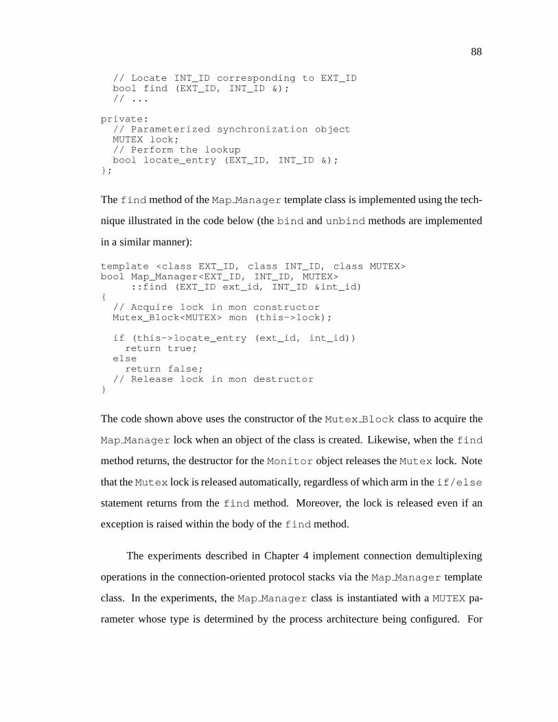
88
// Locate INT_ID corresponding to EXT_IDbool find (EXT_ID, INT_ID &);// ...
private:// Parameterized synchronization objectMUTEX lock;// Perform the lookupbool locate_entry (EXT_ID, INT_ID &);
};
Thefind method of theMap Manager template class is implemented using the tech-
nique illustrated in the code below (thebind andunbind methods are implemented
in a similar manner):
template <class EXT_ID, class INT_ID, class MUTEX>bool Map_Manager<EXT_ID, INT_ID, MUTEX>
::find (EXT_ID ext_id, INT_ID &int_id){
// Acquire lock in mon constructorMutex_Block<MUTEX> mon (this->lock);
if (this->locate_entry (ext_id, int_id))return true;
elsereturn false;
// Release lock in mon destructor}
The code shown above uses the constructor of theMutex Block class to acquire the
Map Manager lock when an object of the class is created. Likewise, when thefind
method returns, the destructor for theMonitor object releases theMutex lock. Note
that theMutex lock is released automatically, regardless of which arm in theif/else
statement returns from thefind method. Moreover, the lock is released even if an
exception is raised within the body of thefind method.
The experiments described in Chapter 4 implement connection demultiplexing
operations in the connection-oriented protocol stacks via theMap Manager template
class. In the experiments, theMap Manager class is instantiated with aMUTEXpa-
rameter whose type is determined by the process architecture being configured. For

89
instance, theMap Manager used in the Message Parallelism implementation of the
transport layer in the protocol stack described in Section 4.5.1 is instantiated with the
following EXT ID , INT ID , andMUTEXtype parameters:
typedef Map_Manager <TCP_Addr, TCB, Mutex> ADDR_MAP;
This particular instantiation ofMap Manager locates the transport control block (TCB)
internal identifier associated with the address of an incomingTCPmessage (TCP Addr )
external identifier. Instantiating theMap Manager class with theMutex class ensures
that itsfind method executes as a critical section. This prevents race conditions from
occurring with other threads of control that are inspecting or inserting entries into the
Map Manager in parallel.
In contrast, the Layer Parallelism implementation of the transport layer in the pro-
tocol stack described in Section 4.5.2 uses a different type of concurrency control. In this
case, serialization is performed at the transport layer using the synchronization mech-
anisms provided by theMessage List defined in theQueue class. Therefore, the
Map Manager used for the Layer Parallelism implementation of the protocol stack is
instantiated with a differentSynch class, as follows:
typedef Map_Manager <TCP_Addr, TCB, Null_Mutex> ADDR_MAP;
The implementation of theacquire andrelease methods in theNull Mutex class
are “no-op” inline functions that are removed completely by the compiler optimizer.
In general, templates generate efficient object code that exacts no additional run-time
overhead for the increased flexibility.
The definition of theMap Manager address map may be conditionally compiled
using template class arguments corresponding to the type of process architecture that is
required,i.e.:

90
typedef// Select a message-based process architecture#if defined (MSG_BASED_PA)Map_Manager <TCP_Addr, TCB, Mutex>// Select a task-based process architecture#elif defined (TASK_BASED_PA)Map_Manager <TCP_Addr, TCB, Null_Mutex>#endifADDR_MAP;
As shown below, this allows the majority of the protocol code to remain unaffected,
regardless of the choice of process architecture, as follows:
ADDR_MAP addr_map;TCP_Addr tcp_addr;TCP tcb;
// ...
if (addr_map.find (tcp_addr, tcb))// Perform connection-oriented processing
3.3.4.2 The ThreadManager Class
TheThread Manager class contains a set of mechanisms that manipulate multi-
ple threads of control atomically. Typically, these threads of control collaborate to imple-
ment collective actions (such as rendering different portions of a large image in parallel).
TheThread Manager class also shields applications from non-portable incompatibil-
ities between different flavors of multi-threading mechanisms (such as POSIX threads,
MACH cthreads, Solaris threads, and Windows NT threads).
The Thread Manager class provides methods (such assuspend all and
resume all ) that suspend and resume a set of collaborating threads of control atom-
ically. This feature is useful for protocol stacks that execute multiple tasks or process
multiple messages in parallel. For example, a Stream implemented using the Layer Par-
allelism process architecture is composed ofModules that execute in separate threads

91
IPC_SAP
A
SOCK_SAP TLI_SAP FIFO_SAPSPIPE_SAP
SOCKET
API
TRANSPORT
LAYER
INTERFACE API
STREAM PIPE
API
NAMED PIPE
API
Figure 3.9:IPC SAPClass Category Relationships
of control. It is crucial that allModules in the Stream are completely interconnected
before allowing messages to be passed betweenQueues in the Stream. The mech-
anisms in theThread Manager class allow these initialization activities to execute
atomically.
3.3.5 TheIPC SAPClass Category
ACE provides a forest of class categories rooted at theIPC SAP(“InterProcess
Communication Service Access Point”) base class.IPC SAP encapsulates the stan-
dard I/O descriptor-based operating system local and remote IPC mechanisms that offer
connection-oriented and connectionless protocols. As shown in Figure 3.9, this forest
of class categories includesSOCKSAP(which encapsulates the socket API),TLI SAP
(which encapsulates the TLI API),SPIPE SAP(which encapsulates the UNIX System
V release 4 STREAM pipe API), andFIFO SAP(which encapsulates the UNIX named
pipe API).

92
Each class category is organized as an inheritance hierarchy. Every subclass pro-
vides a well-defined interface to a subset of local or remote communication mechanisms.
Together, the subclasses within a hierarchy comprise the overall functionality of a partic-
ular communication abstraction (such as the Internet-domain or UNIX-domain protocol
families). The use of classes (as opposed to stand-alone functions) helps to simplify
network programming in the following manner:
� Reduce potential for programmer error– For example, theAddr class hierarchy
shown in Figure 3.9 supports several diverse network addressing formats via a
type-secure C++ interface, rather than using the awkward and error-prone C-based
struct sockaddr data structures directly.
� Combining several operations to form a single operation– For example, the con-
structor in theSOCKListener class performs the various socket system calls
(such assocket , bind , andlisten ) required to create a passive-mode server
endpoint.
� Parameterizing IPC mechanisms into applications– Classes form the basis for
parameterizing an application by the type of IPC mechanism it requires. This
helps to improve portability as discussed in Section 3.3.5.2.
� Enhance code sharing– Inheritance-based hierarchical decomposition increases
the amount of common code that is shared amongst the various IPC mechanisms
(such as the C++ interface to the lower-level UNIX operating system device con-
trol system calls likefcntl andioctl ).
The following sections discuss each of the class categories inIPC SAP.
3.3.5.1 SOCKSAP

93
SOCK_SAPConnect
A
SOCK_SAPDgram
SOCKSAP
Listener
LSOCKSAP
Listener
SOCKSAP
SOCKSAP
CODgram SOCK
SAPStream
SOCK_SAPDgramBrdcast
LSOCKSAP
A
A
LSOCKSAP
Dgram
LSOCKSAP
CODgram
LSOCKSAP
Stream
Addr
INET Addr
UNIX AddrIPCSAP
A
global
global
global
Figure 3.10: TheSOCKSAPInheritance Hierarchy
TheSOCKSAP[Sch92] C++ class category provides applications with an object-
oriented interface to the Internet-domain and UNIX-domain protocol families [Ste90].
Applications may access the functionality of the underlying Internet-domain or UNIX-
domain socket types by inheriting or instantiating the appropriateSOCKSAPsubclasses
shown in Figure 3.10. TheSOCK*subclasses encapsulate Internet-domain functional-
ity and theLSOCK*subclasses encapsulate UNIX-domain functionality. As shown in
Figure 3.10, the subclasses may be further decomposed into (1) the*Dgram compo-
nents (which provide unreliable, connectionless, message-oriented functionality) vs. the
*Stream components (which provide reliable, connection-oriented, bytestream func-
tionality) and (2) the*Listener components (which provide connection establish-
ment functionality typically used by servers) vs. the*Stream components (which
provide bi-directional bytestream data transfer functionality used by both clients and
servers).
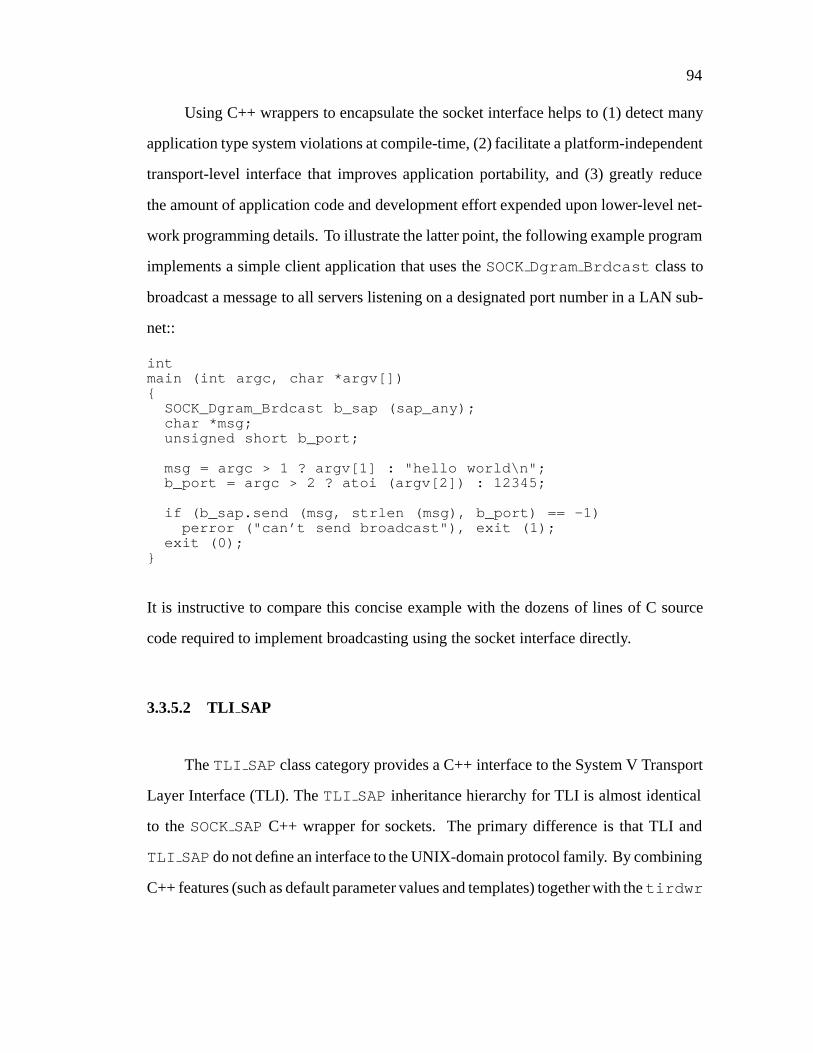
94
Using C++ wrappers to encapsulate the socket interface helps to (1) detect many
application type system violations at compile-time, (2) facilitate a platform-independent
transport-level interface that improves application portability, and (3) greatly reduce
the amount of application code and development effort expended upon lower-level net-
work programming details. To illustrate the latter point, the following example program
implements a simple client application that uses theSOCKDgram Brdcast class to
broadcast a message to all servers listening on a designated port number in a LAN sub-
net::
intmain (int argc, char *argv[]){
SOCK_Dgram_Brdcast b_sap (sap_any);char *msg;unsigned short b_port;
msg = argc > 1 ? argv[1] : "hello world\n";b_port = argc > 2 ? atoi (argv[2]) : 12345;
if (b_sap.send (msg, strlen (msg), b_port) == -1)perror ("can’t send broadcast"), exit (1);
exit (0);}
It is instructive to compare this concise example with the dozens of lines of C source
code required to implement broadcasting using the socket interface directly.
3.3.5.2 TLI SAP
TheTLI SAPclass category provides a C++ interface to the System V Transport
Layer Interface (TLI). TheTLI SAP inheritance hierarchy for TLI is almost identical
to theSOCKSAP C++ wrapper for sockets. The primary difference is that TLI and
TLI SAPdo not define an interface to the UNIX-domain protocol family. By combining
C++ features (such as default parameter values and templates) together with thetirdwr

95
(the read/write compatibility STREAMS module), it becomes relatively straight-
forward to develop applications that may be parameterized at compile-time to operate
correctly over either a socket-based or TLI-based transport interface.
The following code illustrates how C++ templates may be applied to parameterize
the IPC mechanisms used by an application. In the code below, a subclass derived from
Event Handler is parameterized by a particular type of transport interface and its
corresponding protocol address class:
/* Logging_IO header file */template <class XPORT_SAP, class ADDR>class Logging_IO : public Event_Handler{public:
Logging_IO (void);virtual ~Logging_IO (void);
virtual int handle_close (int);virtual int handle_input (int);virtual int get_fd (void) const {
return this->xport_sap.get_fd ();}
protected:XPORT_SAP xport_sap;
};
Depending on certain properties of the underlying OS platform (such as whether it is
BSD-based SunOS 4.x or System V-based SunOS 5.x), the logging application may
instantiate theClient IO class to use eitherSOCKSAPorTLI SAP, as shown below:
/* Logging application */class Logging_IO : public#if defined (MT_SAFE_SOCKETS)Logging_IO<SOCK_Stream, INET_Addr>#elseLogging_IO<TLI_Stream, INET_Addr>#endif /* MT_SAFE_SOCKETS */{
/* ... */};

96
The increased flexibility offered by this template-based approach is extremely use-
ful when developing an application that must run portability across multiple OS plat-
forms. In particular, the ability to parameterize applications according to transport in-
terface is necessary across variants of SunOS platforms since the socket implementation
in SunOS 5.2 is not thread-safe and the TLI implementation in SunOS 4.x contains a
number of serious defects.
TLI SAPalso shields applications from many peculiarities of the TLI interface.
For example, the subtle application-level code required to properly handle the non-
intuitive, error-prone behavior oft listen andt accept in a concurrent server with
aqlen >1 [Rag93] is encapsulated within theaccept method in theTLI Listener
class. This method accepts incoming connection requests from clients. Through the use
of C++ default parameter values, the standard method for calling theaccept method
is syntactically equivalent for bothTLI SAP-based andSOCKSAP-based applications.
3.3.5.3 SPIPESAP
The SPIPE SAPclass category provides a C++ wrapper interface for mounted
STREAM pipes andconnld [PR90]. SunOS 5.x provides thefattach system call
that mounts a pipe descriptor at a designated location in the UNIX file system. A server
application is created by pushing theconnld STREAM module onto the mounted end
of the pipe. When a client application running on the same host machine as the server
subsequently opens the filename associated with the mounted pipe, the client and server
each receive an I/O descriptor that identifies a unique, non-multiplexed, bi-directional
channel of communication.
TheSPIPE SAP inheritance hierarchy mirrors the one used forSOCKSAPand
TLI SAP. It offers functionality that is similar to theSOCKSAP LSOCK*classes (which

97
themselves encapsulate UNIX-domain sockets). However,SPIPE SAP is more flexi-
ble than theLSOCK* interface since it enables STREAM modules to be “pushed” and
“popped” to and fromSPIPE SAPendpoints, respectively.SPIPE SAPalso supports
bi-directional delivery of byte-stream and prioritized message-oriented data between
processes and/or threads executing within the same host machine [Ste92].
3.3.5.4 FIFO SAP
The FIFO SAP class category encapsulates the UNIX named pipe mechanism
(also called FIFOs). Unlike STREAM pipes, named pipes offer only a uni-directional
data channel from one or more senders to a single receiver. Moreover, messages from
different senders are all placed into the same communication channel. Therefore, some
type of demultiplexing identifier must be included explicitly in each message to en-
able the receiver to determine which sender transmitted the message. The STREAMS-
based implementation of named pipes in System V release 4 provides both message-
oriented and bytestream-oriented data delivery semantics. In contrast, SunOS 4.x only
provides bytestream-oriented named pipes. Therefore, unless fixed length messages are
always used, each message sent via a named pipe in SunOS 4.x must be distinguished
by some form of byte count or special termination symbol that allows a receiver to ex-
tract messages from the communication channel bytestream. To alleviate this limitation,
the SunOS 4.xFIFO SAP implementation contains logic that emulates the message-
oriented semantics available in System V release 4.
98
3.4 Summary
Despite an increase in the availability of operating system and hardware platforms
that support networking and parallel processing [EKB+92, Gar90, SPY+93, TRG+87,
Cus93], developing distributed and parallel communication systems remains a complex
and challenging task. The ADAPTIVE Service eXecutive (ASX) provides an extensible
object-oriented framework that simplifies the development of distributed applications
on multi-processor platforms. TheASXframework employs a variety of advanced OS
mechanisms (such as multi-threading and explicit dynamic linking), object-oriented de-
sign techniques (such as encapsulation, hierarchical classification, and deferred compo-
sition) and C++ language features (such as parameterized types, inheritance, and dy-
namic binding) to enhance software quality factors (such as robustness, ease of use,
portability, reusability, and extensibility) without degrading application performance.
In general, the object-oriented techniques and C++ features enhance the software qual-
ity factors, whereas the advanced OS mechanisms improve application functionality and
performance.
TheASXframework components described in this chapter are freely available via
anonymous ftp fromics.uci.edu in the filegnu/C++ wrappers.tar.Z . This
distribution contains complete source code, documentation, and example test drivers for
the C++ components developed as part of the ADAPTIVE project [SBS93, BSS93] at the
University of California, Irvine. Components in theASXframework have been ported to
both UNIX and Windows NT and have been used in a number of commercial products
including the AT&T Q.port ATM signaling software product, the Ericsson EOS family
of PBX monitoring applications, and the network management portion of the Motorola
Iridium mobile communications system.
Chapter 4
Communication Subsystem
Performance Experiments
4.1 Introduction
This chapter presents performance results obtained by measuring the data recep-
tion portion of protocol stacks implemented using several process architectures devel-
oped using theASX framework [SS95b]. Two different types of protocol stacks were
implemented:connection-orientedandconnectionless. Three different variants of task-
based and message-based process architectures were used to parallelize the protocol
stacks:Layer Parallelism(which is a task-based process architecture), as well asMessage-
ParallelismandConnectional Parallelism(which are message-based process architec-
tures). This chapter outlines related work on the performance of parallel process archi-
tectures. It also describes the multi-processor platform and the measurement tools used
in the experiments, as well as the communication protocol stacks and process architec-
tures developed usingASX framework components. Finally, the performance results
from the experiments are presented and analyzed.
99

100
4.2 Related Work
A number of studies have investigated the performance characteristics of task-
based process architectures that ran on either message passing or shared memory plat-
forms. [WF93] measured the performance of several implementations of the transport
and session layers in the ISO OSI reference model using an ADA-like rendezvous-
style of Layer Parallelism in a nonuniform access shared memory multi-processor plat-
form. [LKAS93] measured the performance of Functional Parallelism for presentation
layer and transport layer functionality on a shared memory multi-processor platform.
[BZ93] measured the performance of a de-layered, function-oriented transport system
[ZST93] using Functional Parallelism on a message passing transputer multi-processor
platform. An earlier study [Zit91] measured the performance of the ISO OSI transport
layer and network layer, also on a transputer platform. Likewise, [GKWW89] used a
multi-processor transputer platform to parallelize several data-link layer protocols.
Other studies have investigated the performance characteristics of message-based
process architectures. All these studies utilized shared memory platforms. [HP91] mea-
sured the performance of the TCP, UDP, and IP protocols using Message Parallelism on
a uniprocessor platform running thex-kernel. [Mat93] measured the impact of synchro-
nization on Message Parallelism implementations of TCP and UDP transport protocols
built within a multi-processor version of thex-kernel. Likewise, [NYKT94] examined
performance issues in parallelizing TCP-based and UDP-based protocol stacks using a
different multi-processor version of thex-kernel. [Pre93] measured the performance of
the Nonet transport protocol on a multi-processor version of Plan 9 STREAMS devel-
oped using Message Parallelism. [GNI92] measured the performance of the ISO OSI

101
protocol stack, focusing primarily on the presentation and transport layers using Mes-
sage Parallelism. [SPY+93] measured the performance of the TCP/IP protocol stack
using Connectional Parallelism in a multi-processor version of System V STREAMS.
The research presented in this paper extends existing work by measuring the per-
formance of several representative task-based and message-based process architectures
in a controlled environment. Furthermore, our experiments report the impact of both
context switching and synchronization overhead on communication subsystem perfor-
mance. In addition to measuring data link, network, and transport layer performance,
our experiments also measure presentation layer performance. The presentation layer
is widely considered to be a major bottleneck in high-performance communication sub-
systems [CT90].
4.3 Multi-processor Platform
All experiments were conducted on an otherwise idle Sun SPARCcenter 2000
shared memory symmetric multi-processor. This SPARCcenter platform contained 640
Mbytes of RAM and 20 superscalar SPARC 40 MHz processing elements (PEs), each
rated at approximately 135 MIPs. The operating system used for the experiments was
release 5.3 of SunOS. SunOS 5.3 provides a multi-threaded kernel that allows multi-
ple system calls and device interrupts to execute in parallel on the SPARCcenter plat-
form [EKB+92]. All the process architectures in the experiments execute protocol tasks
using separate SunOS unbound threads. These unbound threads are multiplexed over
1;2;3; . . . 20 SunOS lightweight processes (LWPs) within an OS process. The SunOS
scheduler maps each LWP directly onto a separate kernel thread. Since kernel threads

102
are the units of PE scheduling and execution in SunOS, multiple LWPs run protocol
tasks in parallel on the SPARCcenter 20 PEs.
The memory bandwidth of the SPARCcenter is approximately 750 Mbits/sec. In
addition to memory bandwidth, communication subsystem throughput is significantly
affected by the context switching and synchronization overhead of the multi-processor
platform. Scheduling and synchronizing a SunOS LWP requires a kernel-level context
switch. This context switch flushes register windows and updates instruction and data
caches, instruction pipelines, and translation lookaside buffers [MB91]. These activities
take approximately 50�secs to perform between LWPs running in the same process.
During this time, the PE incurring the context switch does not execute any protocol
tasks.
ASX Mutex andCondition objects were both used in the experiments.Mutex
objects were implemented using SunOS adaptive spin-locks andCondition objects
were implemented using SunOS sleep-locks [EKB+92]. Synchronization methods in-
voked onCondition objects were approximately two orders of magnitude more ex-
pensive compared with methods onMutex objects. For instance, measurements indi-
cated that approximately 4�secs were required to acquire or release aMutex object
when no other PEs contended for the lock. In contrast, when all 20 PEs contended for a
Mutex object, the time required to perform the locking methods increased to approxi-
mately 55�secs.
Approximately 300�secs were required to synchronize LWPs usingCondition
objects when no other PEs contended for the lock. Conversely, when all 20 PEs con-
tended for aCondition object, the time required to perform the locking methods
increased to approximately 520�secs. The two orders of magnitude difference in per-
formance betweenMutex andCondition objects was caused by the more complex

103
algorithms used to implementCondition object methods. In addition, performing
the wait method on aCondition object incurred a context switch, which further
increased the synchronization overhead. In contrast, performing anacquire method
on aMutex object implemented with an adaptive spin-lock rarely triggered a context
switch.
4.4 Functionality of the Communication Protocol Stacks
Two types of protocol stacks were investigated in the experiments. One was based
on the connectionless UDP transport protocol; the other was based on the connection-
oriented TCP transport protocol. Both protocol stacks contained data-link, network,
transport, and presentation layers. The presentation layer was included in the experi-
ments since it represents a major bottleneck in high-performance communication sub-
systems [CT90, GNI92].
Both the connectionless and connection-oriented protocol stacks were developed
by specializing reusable components in theASXframework via inheritance and parame-
terized types. As discussed in Section 3.3.4.1, inheritance and parameterized types were
used to hold protocol stack functionality constant, while the process architecture was
systematically varied. Each layer in a protocol stack was implemented as aModule ,
whose read-side and write-side inherit interfaces and implementations from theQueue
abstract class described in Section 3.3.1. The synchronization and demultiplexing mech-
anisms required to implement different process architectures were parameterized using
C++ template class arguments. As illustrated in Section 3.3.4.1, these templates were
instantiated based upon the type of process architecture being tested.
104
The data-link layer in each protocol stack was implemented by theDLP Module .
This Module transformed network packets received from a network interface into the
canonical message format used internally by the interconnectedQueue components in a
Stream. Preliminary tests conducted with the widely-availablettcp benchmarking tool
indicated that the SPARCcenter multi-processor platform processed messages through a
protocol stack much faster than our 10 Mbps Ethernet network interface was capable of
handling. Therefore, the network interface in our process architecture experiments was
simulated with a single-copy pseudo-device driver operating in loop-back mode. This
approach is consistent with those used in [Mat93, GNI92, NYKT94].
The network and transport layers of the protocol stacks were based on the IP,
UDP, and TCP implementations in the BSD 4.3 Reno release [LMKQ89]. The 4.3 Reno
TCP implementation contains the TCP header prediction enhancements, as well as the
TCP slow start algorithm and congestion avoidance features [Jac88]. The UDP and
TCP transport protocols were configured into theASXframework via theUDPandTCP
Modules . Network layer processing was performed by theIP Module . ThisModule
handled routing and segmentation/reassembly of Internet Protocol (IP) packets.
Presentation layer functionality was implemented in theXDR Module using mar-
shaling routines produced by the ONC eXternal Data Representation (XDR) stub gen-
erator (rpcgen ) [Sun87]. The ONC XDR stub generator translates type specifications
into marshaling routines. These marshaling routines encode/decode implicitly-typed
messages before/after exchanging them among hosts that may possess heterogeneous
processor byte-orders. The ONC presentation layer conversion mechanisms consist of
a type specification language (XDR) and a set of library routines that implement the
appropriate encoding and decoding rules for built-in integral types (e.g.,char, short, int,
and long), as well as real types (e.g.,float and double). These library routines may be
105
combined to produce marshaling routines for arbitrarily complex user-defined compos-
ite types (such as record/structures, unions, arrays, and pointers). Messages exchanged
via XDR are implicitly-typed, which improves marshaling performance at the expense
of run-time flexibility.
TheXDRroutines generated for the connectionless and connection-oriented pro-
tocol stacks converted incoming and outgoing messages into and from variable-sized
arrays of structures containing a set of integral and real values. TheXDRprocessing in-
volved byte-order conversions, as well as dynamic memory allocation and deallocation.
4.5 Structure of the Process Architectures
The remainder of this section outlines the structure of the message-based and
task-based process architectures used to parallelize the connectionless and connection-
oriented protocol stacks described above.
4.5.1 Structure of the Message-based Process Architectures
4.5.1.1 Connectional Parallelism
The protocol stack depicted in Figure 4.1 illustrates anASX-based implementation
of the Connectional Parallelism (CP) process architecture outlined in Section 2.3.1.1.
Each process performs the data-link, network, transport, and presentation layer tasks
sequentially for a single connection. Protocol tasks are divided into four interconnected
Modules , corresponding to the data-link, network, transport, and presentation layers.
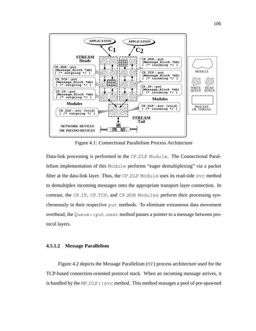
106
APPLICATION APPLICATION
Modules
C1 C2
CP_DLP::svc (void){ /* incoming */ }
CP_DLP::svc (void){ /* outgoing */ }
STREAMHeads
STREAMTail
Modules
NETWORK DEVICESOR PSEUDO-DEVICES
CP_TCP::put(Message_Block *mb){ /* outgoing */ }
CP_IP::put(Message_Block *mb){ /* outgoing */ }
CP_XDR::put(Message_Block *mb){ /* outgoing */ }
CP_XDR::put(Message_Block *mb){ /* incoming */ }
CP_TCP::put(Message_Block *mb){ /* incoming */ }
CP_IP::put(Message_Block *mb){ /* incoming */ }
PROCESSOR THREAD
WRITEQUEUE
READQUEUE
MODULE
Figure 4.1: Connectional Parallelism Process Architecture
Data-link processing is performed in theCP DLP Module . The Connectional Paral-
lelism implementation of thisModule performs “eager demultiplexing” via a packet
filter at the data-link layer. Thus, theCP DLP Module uses its read-sidesvc method
to demultiplex incoming messages onto the appropriate transport layer connection. In
contrast, theCP IP , CP TCP, andCP XDR Modules perform their processing syn-
chronously in their respectiveput methods. To eliminate extraneous data movement
overhead, theQueue::put next method passes a pointer to a message between pro-
tocol layers.
4.5.1.2 Message Parallelism
Figure 4.2 depicts the Message Parallelism (MP) process architecture used for the
TCP-based connection-oriented protocol stack. When an incoming message arrives, it
is handled by theMPDLP::svc method. This method manages a pool of pre-spawned

107
NETWORK DEVICESOR PSEUDO-DEVICES
STREAMHeads
STREAMTail
APPLICATION APPLICATION
Modules
C1 C2
MP_TCP::put(Message_Block *mb){ /* outgoing */ }
MP_IP::put(Message_Block *mb){ /* outgoing */ }
MP_XDR::put(Message_Block *mb){ /* outgoing */ }
MP_XDR::put(Message_Block *mb){ /* incoming */ }
MP_TCP::put(Message_Block *mb){ /* incoming */ }
MP_IP::put(Message_Block *mb){ /* incoming */ }
MP_DLP::svc (void){ /* incoming */ }MP_DLP::svc (void)
{ /* outgoing */ }
ModulesPROCESS
OR THREAD
WRITEQUEUE
READQUEUE
MODULE
Figure 4.2: Message Parallelism Process Architecture
SunOS unbound threads. Each message is associated with an unbound thread that es-
corts the message synchronously through a series of interconnectedQueues that form
a protocol stack. Each layer of the protocol stack performs the protocol tasks defined
by its Queue. When these tasks are complete, an upcall [Cla85] may be used to pass
the message to the next adjacent layer in the protocol stack. The upcall is performed by
invoking theput method in the adjacent layer’sQueue. Thisput method borrows the
thread of control from its caller and executes the protocol tasks associated with its layer.
The Message Parallelism process architecture for the connectionless protocol stack
is similar to the one used to implement the connection-oriented protocol stack. The pri-
mary difference between the two protocol stacks is that the connectionless stack per-
forms UDP transport functionality, which is less complex than TCP. For example, UDP
108
does not generate acknowledgements, keep track of round-trip time estimates, or man-
age congestion windows. In addition, the connectionlessMPUDP::put method han-
dles each message concurrently and independently, without explicitly preserving inter-
message ordering. In contrast, the connection-orientedMPTCP::put method utilizes
severalMutex synchronization objects. As separate messages from the same connec-
tion ascend the protocol stack in parallel, theseMutex objects serialize access to per-
connection control blocks. Serialization is required to protect shared resources (such as
message queues, protocol connection records, TCP segment reassembly, and demulti-
plexing tables) against race conditions.
Both Connectional Parallelism and Message Parallelism optimize message man-
agement by using SunOS thread-specific storage [EKB+92] to buffer messages as they
flow through a protocol stack. This optimization leverages off the cache affinity prop-
erties of the SunOS shared memory multi-processor. In addition, it minimizes the cost
of synchronization operations used to manage the global dynamic memory heap.
4.5.2 Structure of the Task-based Process Architecture
4.5.2.1 Layer Parallelism
Figure 4.3 illustrates theASXframework components that implement a Layer Par-
allelism (LP) process architecture for the TCP-based connection-oriented protocol stack.
The connectionless UDP-based protocol stack for Layer Parallelism was designed in a
similar manner. The primary difference between them was that the read-side and write-
sideQueues in the connectionless transport layerModule (LP UDP) implement the
simpler UDP functionality.
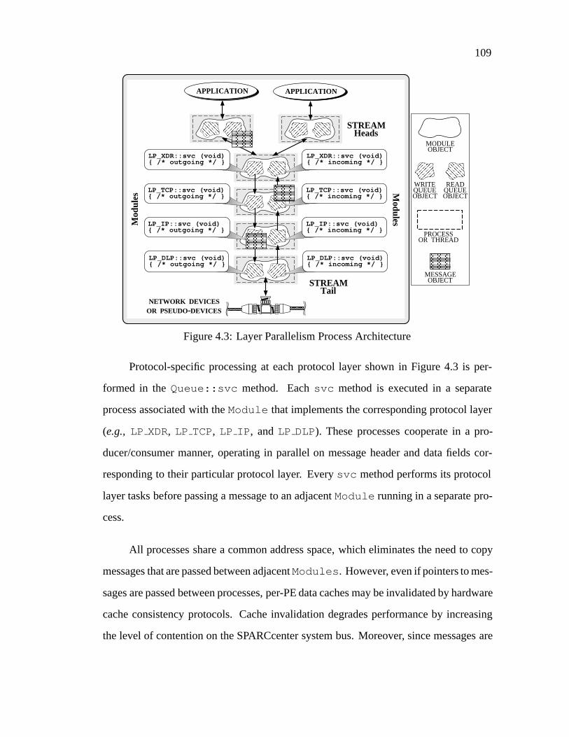
109
STREAMHeads
STREAMTail
APPLICATION
Modules
NETWORK DEVICESOR PSEUDO-DEVICES
APPLICATION
Mod
ules
PROCESSOR THREAD
WRITEQUEUEOBJECT
READQUEUEOBJECT
MODULEOBJECT
MESSAGEOBJECT
LP_DLP::svc (void){ /* outgoing */ }
LP_TCP::svc (void){ /* outgoing */ }
LP_IP::svc (void){ /* outgoing */ }
LP_XDR::svc (void){ /* outgoing */ }
LP_DLP::svc (void){ /* incoming */ }
LP_TCP::svc (void){ /* incoming */ }
LP_IP::svc (void){ /* incoming */ }
LP_XDR::svc (void){ /* incoming */ }
Figure 4.3: Layer Parallelism Process Architecture
Protocol-specific processing at each protocol layer shown in Figure 4.3 is per-
formed in theQueue::svc method. Eachsvc method is executed in a separate
process associated with theModule that implements the corresponding protocol layer
(e.g., LP XDR, LP TCP, LP IP , andLP DLP). These processes cooperate in a pro-
ducer/consumer manner, operating in parallel on message header and data fields cor-
responding to their particular protocol layer. Everysvc method performs its protocol
layer tasks before passing a message to an adjacentModule running in a separate pro-
cess.
All processes share a common address space, which eliminates the need to copy
messages that are passed between adjacentModules . However, even if pointers to mes-
sages are passed between processes, per-PE data caches may be invalidated by hardware
cache consistency protocols. Cache invalidation degrades performance by increasing
the level of contention on the SPARCcenter system bus. Moreover, since messages are
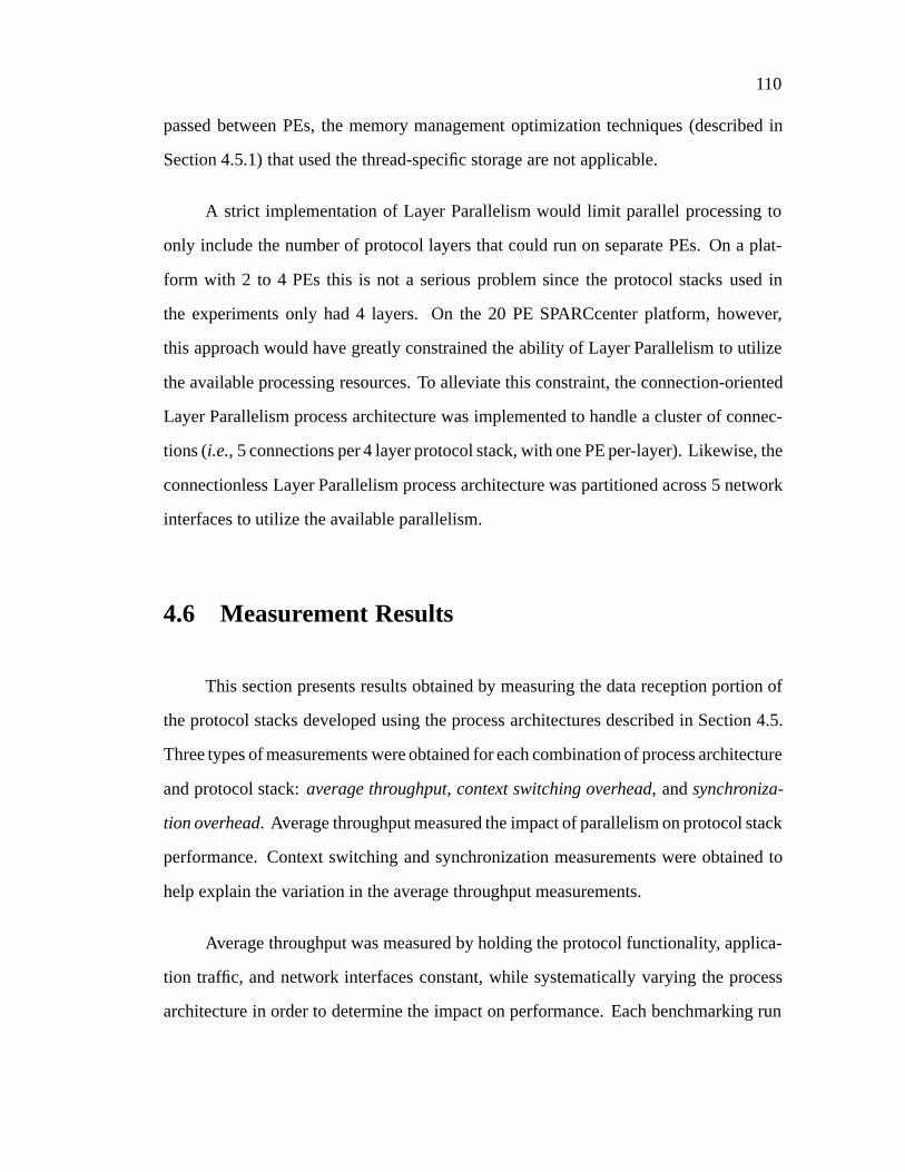
110
passed between PEs, the memory management optimization techniques (described in
Section 4.5.1) that used the thread-specific storage are not applicable.
A strict implementation of Layer Parallelism would limit parallel processing to
only include the number of protocol layers that could run on separate PEs. On a plat-
form with 2 to 4 PEs this is not a serious problem since the protocol stacks used in
the experiments only had 4 layers. On the 20 PE SPARCcenter platform, however,
this approach would have greatly constrained the ability of Layer Parallelism to utilize
the available processing resources. To alleviate this constraint, the connection-oriented
Layer Parallelism process architecture was implemented to handle a cluster of connec-
tions (i.e.,5 connections per 4 layer protocol stack, with one PE per-layer). Likewise, the
connectionless Layer Parallelism process architecture was partitioned across 5 network
interfaces to utilize the available parallelism.
4.6 Measurement Results
This section presents results obtained by measuring the data reception portion of
the protocol stacks developed using the process architectures described in Section 4.5.
Three types of measurements were obtained for each combination of process architecture
and protocol stack:average throughput, context switching overhead, andsynchroniza-
tion overhead. Average throughput measured the impact of parallelism on protocol stack
performance. Context switching and synchronization measurements were obtained to
help explain the variation in the average throughput measurements.
Average throughput was measured by holding the protocol functionality, applica-
tion traffic, and network interfaces constant, while systematically varying the process
architecture in order to determine the impact on performance. Each benchmarking run
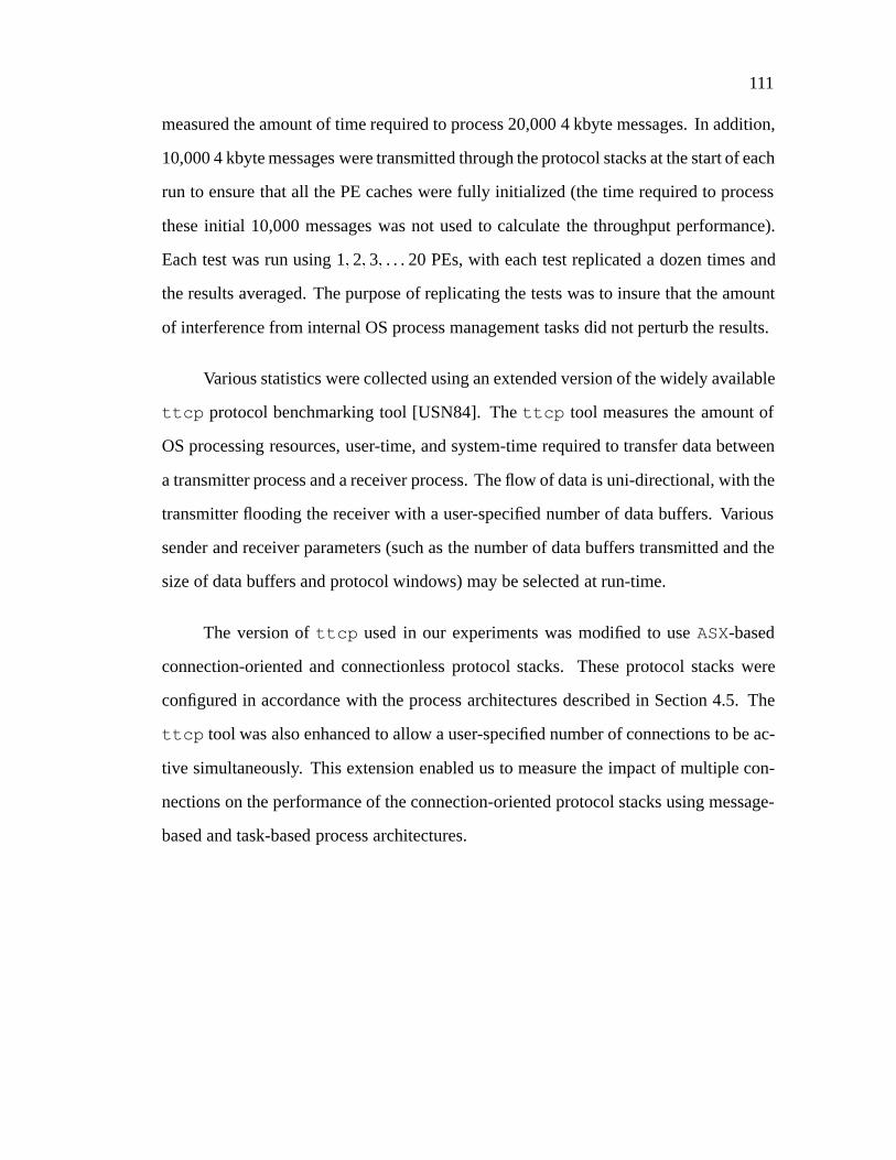
111
measured the amount of time required to process 20,000 4 kbyte messages. In addition,
10,000 4 kbyte messages were transmitted through the protocol stacks at the start of each
run to ensure that all the PE caches were fully initialized (the time required to process
these initial 10,000 messages was not used to calculate the throughput performance).
Each test was run using 1;2;3; . . . 20 PEs, with each test replicated a dozen times and
the results averaged. The purpose of replicating the tests was to insure that the amount
of interference from internal OS process management tasks did not perturb the results.
Various statistics were collected using an extended version of the widely available
ttcp protocol benchmarking tool [USN84]. Thettcp tool measures the amount of
OS processing resources, user-time, and system-time required to transfer data between
a transmitter process and a receiver process. The flow of data is uni-directional, with the
transmitter flooding the receiver with a user-specified number of data buffers. Various
sender and receiver parameters (such as the number of data buffers transmitted and the
size of data buffers and protocol windows) may be selected at run-time.
The version ofttcp used in our experiments was modified to useASX-based
connection-oriented and connectionless protocol stacks. These protocol stacks were
configured in accordance with the process architectures described in Section 4.5. The
ttcp tool was also enhanced to allow a user-specified number of connections to be ac-
tive simultaneously. This extension enabled us to measure the impact of multiple con-
nections on the performance of the connection-oriented protocol stacks using message-
based and task-based process architectures.

112
● ● ● ● ●● ● ● ● ● ● ● ● ● ● ● ● ● ● ●
❍❍
❍
❍❍
❍❍ ❍
❍❍
❍❍
❍❍
❍ ❍❍
❍❍ ❍
1 2 3 4 5 6 7 8 9 10111213141516171819200
50
100
150
200
250
300
350
400
Ave
rage
Thr
ough
put (
Mbi
ts/s
ec)
Number of Processing Elements
● With Presentation Layer
❍ Without Presentation Layer
Figure 4.4: Connection-oriented Connectional Parallelism Throughput
4.6.1 Throughput Measurements
Figures 4.4, 4.5, and 4.6 depict the average throughput for the message-based
process architectures (Connectional Parallelism and Message Parallelism) and the task-
based process architecture (Layer Parallelism) used to implement the connection-oriented
protocol stacks. Each test run for these connection-oriented process architectures used
20 connections. These figures report the average throughput (in Mbits/sec), measured
both with and without presentation layer processing. The figures illustrate how through-
put is affected as the number of PEs increase from 1 to 20. Figures 4.7, 4.8, and 4.9
indicate the relative speedup that resulted from successively adding another PE to each
process architecture. Relative speedup is computed by dividing the average aggregated
throughput forn PEs (shown in Figures 4.4, 4.5, and 4.6, where 1� n � 20) by the
average throughput for 1 PE.
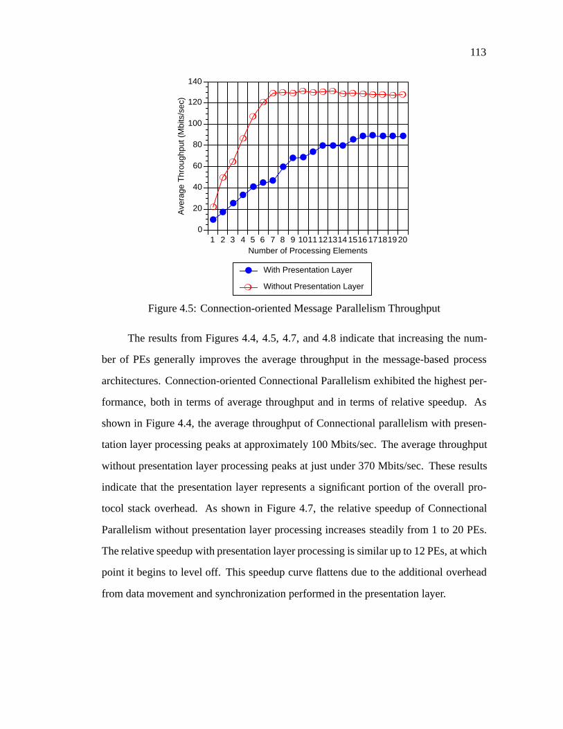
113
●●
●●
●● ●
●● ●
●● ● ●
● ● ● ● ● ●
❍
❍
❍
❍
❍
❍❍ ❍ ❍ ❍ ❍ ❍ ❍ ❍ ❍ ❍ ❍ ❍ ❍ ❍
1 2 3 4 5 6 7 8 9 10111213141516171819200
20
40
60
80
100
120
140
Ave
rage
Thr
ough
put (
Mbi
ts/s
ec)
Number of Processing Elements
● With Presentation Layer
❍ Without Presentation Layer
Figure 4.5: Connection-oriented Message Parallelism Throughput
The results from Figures 4.4, 4.5, 4.7, and 4.8 indicate that increasing the num-
ber of PEs generally improves the average throughput in the message-based process
architectures. Connection-oriented Connectional Parallelism exhibited the highest per-
formance, both in terms of average throughput and in terms of relative speedup. As
shown in Figure 4.4, the average throughput of Connectional parallelism with presen-
tation layer processing peaks at approximately 100 Mbits/sec. The average throughput
without presentation layer processing peaks at just under 370 Mbits/sec. These results
indicate that the presentation layer represents a significant portion of the overall pro-
tocol stack overhead. As shown in Figure 4.7, the relative speedup of Connectional
Parallelism without presentation layer processing increases steadily from 1 to 20 PEs.
The relative speedup with presentation layer processing is similar up to 12 PEs, at which
point it begins to level off. This speedup curve flattens due to the additional overhead
from data movement and synchronization performed in the presentation layer.

114
●
●
●
●
●● ● ● ● ●
● ● ●●
● ● ●● ● ●
❍
❍❍
❍❍
❍ ❍ ❍ ❍ ❍ ❍❍
❍❍
❍❍
❍❍
❍❍
1 2 3 4 5 6 7 8 9 10111213141516171819200
5
10
15
20
25
30
35
40
Ave
rage
Thr
ough
put (
Mbi
ts/s
ec)
Number of Processing Elements
● With Presentation Layer
❍ Without Presentation Layer
Figure 4.6: Connection-oriented Layer Parallelism Throughput
As shown in Figure 4.5, the average throughput achieved by connection-oriented
Message Parallelism without presentation layer processing peaks at 130 Mbits/sec. When
presentation layer processing is performed, the average throughput is 1.5 to 3 times
lower, peaking at approximately 90 Mbits/sec. Note, however, that the relative speedup
without presentation layer processing (shown in Figure 4.8) flattens out after 8 CPUs.
This speedup curve flattens out when presentation layer processing is omitted due to
increased contention for shared synchronization objects at the transport layer. This syn-
chronization overhead is discussed further in Section 4.6.3. In contrast, the relative
speedup of connection-oriented Message Parallelism with presentation layer processing
grows steadily from 1 to 20 PEs. This behavior suggests that connection-oriented Mes-
sage Parallelism benefits more from parallelism when the protocol stack contains presen-
tation layer processing. This finding is consistent with those reported in [NYKT94], and
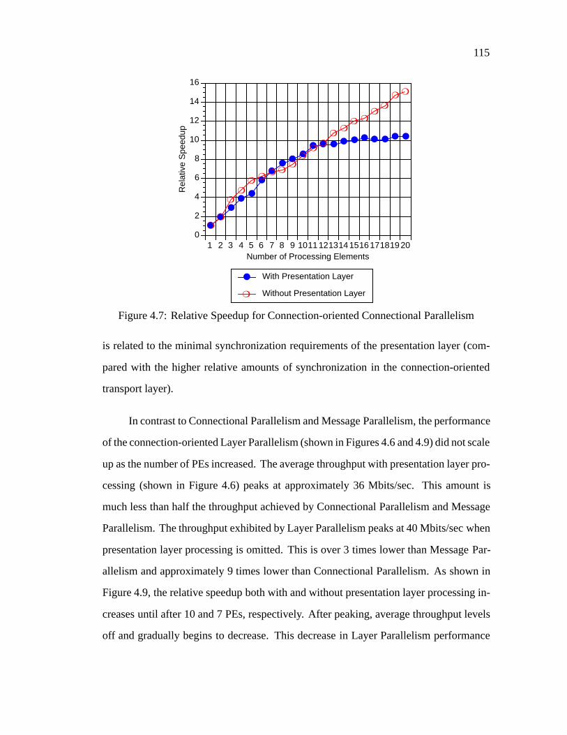
115
●●
●●
●
●●
●●
●● ● ● ● ● ● ● ● ● ●
❍❍
❍❍
❍❍
❍ ❍❍
❍❍
❍❍
❍❍ ❍
❍❍
❍ ❍
1 2 3 4 5 6 7 8 9 10111213141516171819200
2
4
6
8
10
12
14
16
Rel
ativ
e S
peed
up
Number of Processing Elements
● With Presentation Layer
❍ Without Presentation Layer
Figure 4.7: Relative Speedup for Connection-oriented Connectional Parallelism
is related to the minimal synchronization requirements of the presentation layer (com-
pared with the higher relative amounts of synchronization in the connection-oriented
transport layer).
In contrast to Connectional Parallelism and Message Parallelism, the performance
of the connection-oriented Layer Parallelism (shown in Figures 4.6 and 4.9) did not scale
up as the number of PEs increased. The average throughput with presentation layer pro-
cessing (shown in Figure 4.6) peaks at approximately 36 Mbits/sec. This amount is
much less than half the throughput achieved by Connectional Parallelism and Message
Parallelism. The throughput exhibited by Layer Parallelism peaks at 40 Mbits/sec when
presentation layer processing is omitted. This is over 3 times lower than Message Par-
allelism and approximately 9 times lower than Connectional Parallelism. As shown in
Figure 4.9, the relative speedup both with and without presentation layer processing in-
creases until after 10 and 7 PEs, respectively. After peaking, average throughput levels
off and gradually begins to decrease. This decrease in Layer Parallelism performance
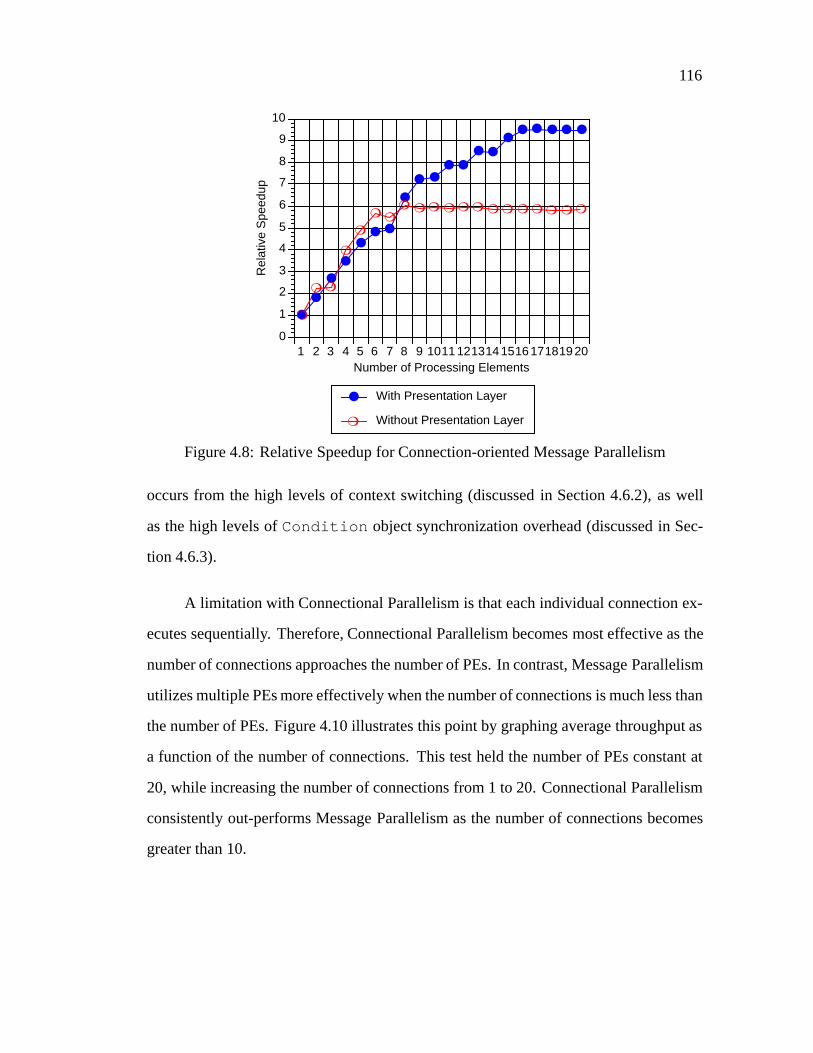
116
●
●
●
●
●● ●
●
● ●● ●
● ●●
● ● ● ● ●
❍
❍ ❍
❍
❍
❍ ❍❍ ❍ ❍ ❍ ❍ ❍ ❍ ❍ ❍ ❍ ❍ ❍ ❍
1 2 3 4 5 6 7 8 9 10111213141516171819200
1
2
3
4
5
6
7
8
9
10
Rel
ativ
e S
peed
up
Number of Processing Elements
● With Presentation Layer
❍ Without Presentation Layer
Figure 4.8: Relative Speedup for Connection-oriented Message Parallelism
occurs from the high levels of context switching (discussed in Section 4.6.2), as well
as the high levels ofCondition object synchronization overhead (discussed in Sec-
tion 4.6.3).
A limitation with Connectional Parallelism is that each individual connection ex-
ecutes sequentially. Therefore, Connectional Parallelism becomes most effective as the
number of connections approaches the number of PEs. In contrast, Message Parallelism
utilizes multiple PEs more effectively when the number of connections is much less than
the number of PEs. Figure 4.10 illustrates this point by graphing average throughput as
a function of the number of connections. This test held the number of PEs constant at
20, while increasing the number of connections from 1 to 20. Connectional Parallelism
consistently out-performs Message Parallelism as the number of connections becomes
greater than 10.

117
●
●
●
●
●
● ● ● ●●
● ● ●●
● ● ●●
● ●
❍
❍❍
❍ ❍❍
❍
❍❍ ❍ ❍
❍ ❍ ❍❍
❍ ❍ ❍ ❍❍
1 2 3 4 5 6 7 8 9 10111213141516171819200
0.5
1
1.5
2
2.5
3
3.5
4
Rel
ativ
e S
peed
up
Number of Processing Elements
● With Presentation Layer
❍ Without Presentation Layer
Figure 4.9: Relative Speedup for Connection-oriented Layer Parallelism
Figures 4.11 and 4.12 depict the average throughput for the message-based and
task-based process architectures used to implement the connectionless protocol stacks
(note that Connectional Parallelism is not applicable for a connectionless protocol stack).
These figures report the throughput measured both with and without presentation layer
processing. Figures 4.13 and 4.14 indicate the speedup of each process architecture,
relative to its single PE case, for the data points reported in Figures 4.11 and 4.12.
The connectionless message-based process architecture (Figure 4.11) significantly
outperforms the task-based process architecture (Figure 4.12). This behavior is consis-
tent with the results from the connection-oriented tests shown in Figure 4.4 through
Figure 4.9. With presentation layer processing, the throughput and relative speedup of
connectionless Message Parallelism is slightly higher than the connection-oriented ver-
sion shown in Figures 4.5 and 4.8. However, without presentation layer processing, the
throughput and relative speedup of connectionless Message Parallelism are substantially
higher (500 Mbits/sec vs. 130 Mbits/sec). In addition, note that the relative speedup of

118
● ● ● ●● ● ●
● ●●
● ● ●●
● ● ● ● ● ●
❍
❍
❍
❍
❍
❍
❍
❍
❍ ❍❍
❍❍
❍ ❍ ❍ ❍ ❍ ❍ ❍
1 2 3 4 5 6 7 8 9 10111213141516171819200
10
20
30
40
50
60
70
80
90
100
Ave
rage
Thr
ough
put (
Mbi
ts/s
ec)
Number of Connections
● Connection-oriented Message Parallelism
❍ Connection-oriented Connectional Parallelism
Figure 4.10: Comparison of Connectional Parallelism and Message Parallelism
connectionless Message Parallelism without presentation layer processing exceeds that
attained with presentation layer processing (shown in Figure 4.13). This behavior is the
reverse of the connection-oriented Message Parallelism results (shown in Figure 4.8).
The difference in performance is due to the fact that connectionless Message Parallelism
incurs much lower levels of synchronization overhead (synchronization is discussed fur-
ther in Section 4.6.3).
The throughput of the connectionless Layer Parallelism (shown in Figure 4.12)
suffered from the same problems as the connection-oriented version (shown in Fig-
ure 4.6). As shown in Figure 4.9, the relative speedup increases only up to 6 PEs, re-
gardless of whether presentation layer processing was performed or not. At this point,
the performance levels off and begins to decrease. This behavior is accounted for by the
high levels of Layer Parallelism context switching discussed in the following section.
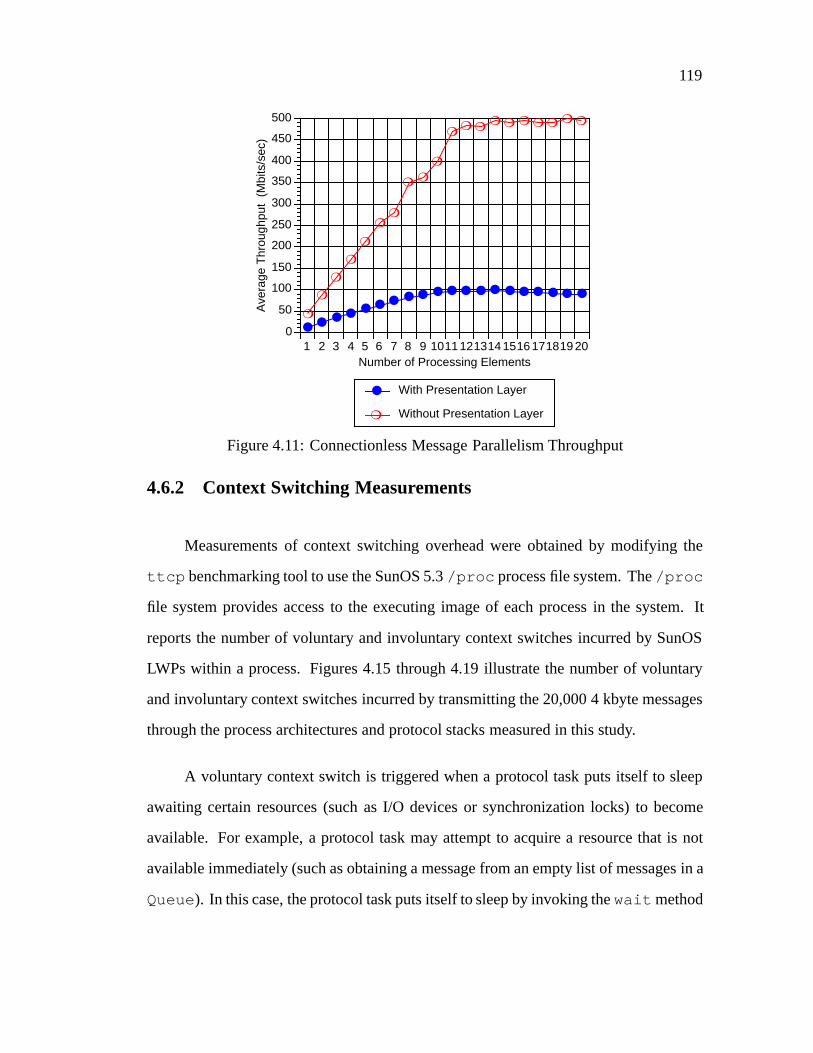
119
● ● ● ● ● ● ● ● ● ● ● ● ● ● ● ● ● ● ● ●
❍
❍
❍
❍
❍
❍❍
❍ ❍
❍
❍❍ ❍
❍ ❍ ❍ ❍ ❍ ❍ ❍
1 2 3 4 5 6 7 8 9 10111213141516171819200
50
100
150
200
250
300
350
400
450
500
Ave
rage
Thr
ough
put
(Mbi
ts/s
ec)
Number of Processing Elements
● With Presentation Layer
❍ Without Presentation Layer
Figure 4.11: Connectionless Message Parallelism Throughput
4.6.2 Context Switching Measurements
Measurements of context switching overhead were obtained by modifying the
ttcp benchmarking tool to use the SunOS 5.3/proc process file system. The/proc
file system provides access to the executing image of each process in the system. It
reports the number of voluntary and involuntary context switches incurred by SunOS
LWPs within a process. Figures 4.15 through 4.19 illustrate the number of voluntary
and involuntary context switches incurred by transmitting the 20,000 4 kbyte messages
through the process architectures and protocol stacks measured in this study.
A voluntary context switch is triggered when a protocol task puts itself to sleep
awaiting certain resources (such as I/O devices or synchronization locks) to become
available. For example, a protocol task may attempt to acquire a resource that is not
available immediately (such as obtaining a message from an empty list of messages in a
Queue). In this case, the protocol task puts itself to sleep by invoking thewait method

120
●
●
●
● ● ●● ●
● ● ●● ● ● ●
● ●● ● ●
❍
❍ ❍❍
❍ ❍❍ ❍ ❍
❍ ❍ ❍❍ ❍
❍❍
❍❍ ❍ ❍
1 2 3 4 5 6 7 8 9 10111213141516171819200
5
10
15
20
25
30
35
40
45
50
Ave
rage
Thr
ough
put (
Mbi
ts/s
ec)
Number of Processing Elements
● With Presentation Layer
❍ Without Presentation Layer
Figure 4.12: Connectionless Layer Parallelism Throughput
of anASX Condition object. This method causes the SunOS kernel to preempt the
current thread of control and perform a context switch to another thread of control that
is capable of executing protocol tasks immediately. For each combination of process
architecture and protocol stack, voluntary context switching increases fairly steadily as
the number of PEs increase from 1 through 20 (shown in Figures 4.15 through 4.19).
An involuntary context switch occurs when the SunOS kernel preempts a running
unbound thread in order to schedule another thread of control to execute other protocol
tasks. The SunOS scheduler preempts an active thread of control every 10 milliseconds
when the time-slice alloted to its LWP expires. Note that the rate of growth for involun-
tary context switching shown in Figures 4.15 through 4.19 remains fairly consistent as
the number of PEs increase. Therefore, it appears that most of the variance in average
throughput performance is accounted for by voluntary context switching, rather than by
involuntary context switching.

121
●
●
●
●
●●
●●
●● ● ● ● ● ● ● ● ● ● ●
❍
❍
❍
❍
❍
❍❍
❍ ❍
❍
❍❍ ❍
❍ ❍ ❍ ❍ ❍ ❍ ❍
1 2 3 4 5 6 7 8 9 10111213141516171819200
2
4
6
8
10
12
Rel
ativ
e S
peed
up
Number of Processing Elements
● With Presentation Layer
❍ Without Presentation Layer
Figure 4.13: Relative Speedup for Connectionless Message Parallelism
The task-based process architectures (shown in Figures 4.18 and 4.19) exhib-
ited approximately 4 to 5 times higher levels of voluntary context switching than the
message-based process architectures (shown in Figures 4.15, 4.16, and 4.17). This dif-
ference stems from the synchronization mechanisms used for the Layer Parallelism pro-
cess architecture. This process architecture uses sleep-locks to implement flow control
between protocol stack layers running in separate PEs. This type of flow control is nec-
essary since processing activities in each layer may execute at different rates. In SunOS,
thewait andsignal methods onCondition objects are implemented using sleep-
locks, which trigger voluntary context switches. In contrast, Connectional Parallelism
and Message Parallelism use adaptive spin-lock synchronization, which is less costly
since it typically doesnot trigger voluntary context switches. The substantially lower-
levels of voluntary context switching exhibited by Connectional Parallelism and Mes-
sage Parallelism helps to account for their consistently higher overall throughput and
greater relative speedup discussed in Section 4.6.1.
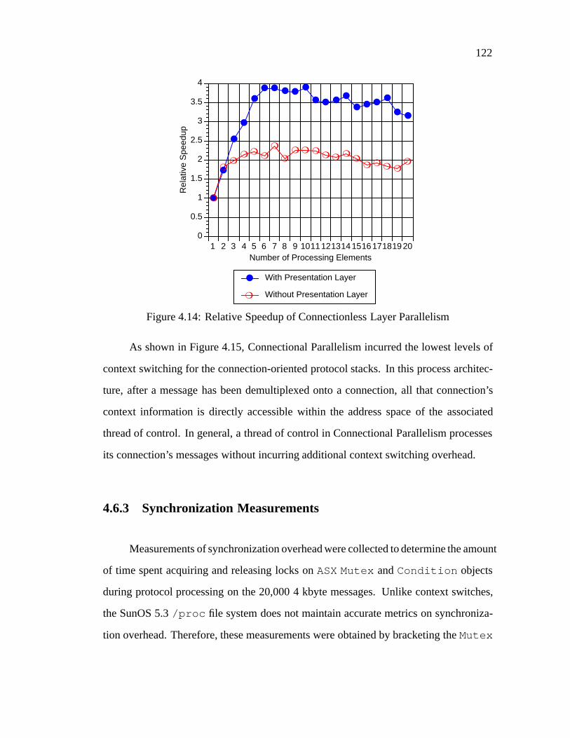
122
●
●
●
●
●
● ● ● ●●
● ● ●●
● ● ●●
● ●
❍
❍❍
❍ ❍❍
❍
❍❍ ❍ ❍
❍ ❍ ❍❍
❍ ❍ ❍ ❍❍
1 2 3 4 5 6 7 8 9 10111213141516171819200
0.5
1
1.5
2
2.5
3
3.5
4
Rel
ativ
e S
peed
up
Number of Processing Elements
● With Presentation Layer
❍ Without Presentation Layer
Figure 4.14: Relative Speedup of Connectionless Layer Parallelism
As shown in Figure 4.15, Connectional Parallelism incurred the lowest levels of
context switching for the connection-oriented protocol stacks. In this process architec-
ture, after a message has been demultiplexed onto a connection, all that connection’s
context information is directly accessible within the address space of the associated
thread of control. In general, a thread of control in Connectional Parallelism processes
its connection’s messages without incurring additional context switching overhead.
4.6.3 Synchronization Measurements
Measurements of synchronization overhead were collected to determine the amount
of time spent acquiring and releasing locks onASX Mutex andCondition objects
during protocol processing on the 20,000 4 kbyte messages. Unlike context switches,
the SunOS 5.3/proc file system does not maintain accurate metrics on synchroniza-
tion overhead. Therefore, these measurements were obtained by bracketing theMutex

123
● ●●
● ● ●●
●
●
●●
● ●
●●
●●
● ●●
❍ ❍ ❍❍
❍
❍❍
❍ ❍ ❍ ❍ ❍ ❍ ❍ ❍ ❍❍ ❍ ❍ ❍
1 2 3 4 5 6 7 8 9 10111213141516171819200
2000
4000
6000
8000
10000
12000
14000
Num
ber
of C
onte
xt S
witc
hes
Number of Processing Elements
● Voluntary Context Switches
❍ Involuntary Context Switches
Figure 4.15: Connection-oriented Connectional Parallelism Context Switching
andCondition methods with calls to thegethrtime system call. This system call
uses the SunOS 5.3 high-resolution timer, which expresses time in nanoseconds from
an arbitrary time in the past. The time returned by thegethrtime system call is not
subject to resetting or drifting since it is not correlated with the current time of day.
Figures 4.20 through 4.24 indicate the total time (measured in msecs) used to ac-
quire and release locks onMutex andCondition synchronization objects. These
tests were performed using all three process architectures to implement connection-
oriented and connectionless protocol stacks that contained data-link, network, transport,
and presentation layer functionality. The message-based process architectures (Con-
nectional Parallelism and Message Parallelism, shown in Figures 4.20, 4.21, and 4.23)
usedMutex synchronization mechanisms that utilize adaptive spin-locks (which rarely
trigger a context switch). In contrast, the task-based process architecture (Layer Paral-
lelism, shown in Figures 4.22 and 4.24) utilized bothMutex andCondition objects
(Condition objectsdo trigger context switches).

124
● ● ●●
●●
● ●
● ● ●
●●
●
● ●
● ●● ●
❍ ❍ ❍ ❍ ❍ ❍ ❍ ❍❍ ❍ ❍ ❍ ❍ ❍
❍ ❍ ❍ ❍ ❍ ❍
1 2 3 4 5 6 7 8 9 10111213141516171819200
5000
10000
15000
20000
25000
Num
ber
of C
onte
xt S
witc
hes
Number of Processing Elements
● Voluntary Context Switches
❍ Involuntary Context Switches
Figure 4.16: Connection-oriented Message Parallelism Context Switching
Connection-oriented Connectional Parallelism (shown in Figure 4.20) exhibited
the lowest levels of synchronization overhead, which peaked at approximately 700 msecs.
This synchronization overhead was approximately 1 order of magnitude lower than the
results shown in Figures 4.21 through 4.24. Moreover, the amount of synchronization
overhead incurred by Connectional Parallelism did not increase significantly as the num-
ber of PEs increased from 1 to 20. This behavior occurs since after a message is demulti-
plexed onto a PE/connection, few additional synchronization operations are required. In
addition, since Connectional Parallelism processes messages within a single PE cache,
it leverages off of SPARCcenter 2000 multi-processor cache affinity properties [VZ91].
The synchronization overhead incurred by connection-oriented Message Paral-
lelism (shown in Figure 4.21) peaked at just over 6,000 msecs. Moreover, the rate of
growth increased fairly steadily as the number of PEs increased from 1 to 20. This be-
havior occurs from the lock contention caused byMutex objects that serialize access

125
● ● ● ● ●● ●
●●
●
●
●
●
●●
●
● ●● ●
❍ ❍ ❍ ❍ ❍ ❍ ❍ ❍ ❍ ❍ ❍ ❍ ❍ ❍ ❍ ❍ ❍ ❍ ❍ ❍
1 2 3 4 5 6 7 8 9 10111213141516171819200
5000
10000
15000
20000
25000
30000
Num
ber
of C
onte
xt S
witc
hes
Number of Processing Elements
● Voluntary Context Switches
❍ Involuntary Context Switches
Figure 4.17: Connectionless Message Parallelism Context Switching
to theMap Manager connection demultiplexer (discussed in Section 3.3.4.1). In con-
trast, the connectionless Message Parallelism protocol stack does not require the use of
this connection demultiplexer. Therefore, the amount of synchronization overhead it
incurred was much lower, peaking at under 1,800 msecs.
Connection-oriented Layer Parallelism exhibited two types of synchronization
overhead (shown in Figure 4.22). The amount of overhead resulting fromMutex ob-
jects peaked at just over 2,000 msecs, which was lower than that of connection-oriented
Message Parallelism (shown in Figure 4.21). However, the amount of synchronization
overhead from theCondition objects was much higher, peaking at approximately
18,000 msecs (shown in Figure 4.22). In the Layer Parallelism implementation, the
Condition objects implemented flow control between separate layers executing on
different PEs in a protocol stack. The connectionless version of Layer Parallelism also
exhibited high levels of synchronization overhead (shown in Figure 4.24).

126
● ● ●●
●
●
●
●● ● ●
●● ●
●● ●
●
● ●
❍❍
❍❍ ❍ ❍ ❍ ❍ ❍ ❍ ❍ ❍ ❍ ❍ ❍ ❍ ❍ ❍ ❍ ❍
1 2 3 4 5 6 7 8 9 10111213141516171819200
10000
20000
30000
40000
50000
60000
70000
80000
90000
100000
Num
ber
of C
onte
xt S
witc
hes
Number of Processing Elements
● Voluntary Context Switches
❍ Involuntary Context Switches
Figure 4.18: Connection-oriented Layer Parallelism Context Switching
4.7 Summary
The following observations resulted from our experience gained by conducting
performance experiments on alternative process architectures for connectionless and
connection-oriented protocol stacks:
� Implementing the task-based process architectures was relatively straightforward.
These process architectures map onto conventional layered communication mod-
els using well-structured “producer/consumer” designs [Atk88]. Minimal syn-
chronization was necessarywithin a layer since parallel processing was serialized
at a service access point (such as the service access point defined between the
network and transport layers). However, as shown by the performance experi-
ments, the task-based Layer Parallelism process architecture exhibited high levels
of context switching and synchronization overhead on the SunOS shared memory
multi-processor platform.

127
● ● ●●
●
●
●
●● ● ●
●● ●
●● ●
●
● ●
❍❍
❍❍ ❍ ❍ ❍ ❍ ❍ ❍ ❍ ❍ ❍ ❍ ❍ ❍ ❍ ❍ ❍ ❍
1 2 3 4 5 6 7 8 9 10111213141516171819200
10000
20000
30000
40000
50000
60000
70000
80000
90000
100000
Num
ber
of C
onte
xt S
witc
hes
Number of Processing Elements
● Voluntary Context Switches
❍ Involuntary Context Switches
Figure 4.19: Connectionless Layer Parallelism Context Switching
� Implementing the message-based process architectures was challenging since the
concurrency control mechanisms were more complex. However, the message-
based process architectures used parallelism more effectively than the task-based
process architectures. This is due in part to the fact that message-based process ar-
chitecture parallelism was based upon dynamic characteristics (such as messages
or connections). This dynamism enables the message-based process architectures
to use a larger number of PEs effectively. As described in Section 4.6.1, the rela-
tive speedups gained from parallel message-based process architectures scaled up
to use a relatively high number of PEs. In contrast, the parallelism used by the
task-based process architectures depended on relatively static characteristics (such
as the number of layers or protocol tasks), which did not scale up. In addition,
the higher rate of growth for context switching and synchronization (discussed in
Sections 4.6.2 and 4.6.3) hampered the ability of Layer Parallelism to effectively
utilize a large number of PEs.
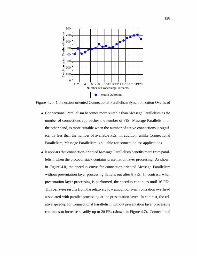
128
●
●
●●
● ● ●
●● ●
● ●●
●●
● ●● ●
●
1 2 3 4 5 6 7 8 9 10111213141516171819200
100
200
300
400
500
600
700
800
Syn
chro
niza
tion
Ove
rhea
d (m
secs
)
Number of Processing Elements
● Mutex Overhead
Figure 4.20: Connection-oriented Connectional Parallelism Synchronization Overhead
� Connectional Parallelism becomes more suitable than Message Parallelism as the
number of connections approaches the number of PEs. Message Parallelism, on
the other hand, is more suitable when the number of active connections is signif-
icantly less than the number of available PEs. In addition, unlike Connectional
Parallelism, Message Parallelism is suitable for connectionless applications.
� It appears that connection-oriented Message Parallelism benefits more from paral-
lelism when the protocol stack contains presentation layer processing. As shown
in Figure 4.8, the speedup curve for connection-oriented Message Parallelism
without presentation layer processing flattens out after 8 PEs. In contrast, when
presentation layer processing is performed, the speedup continues until 16 PEs.
This behavior results from the relatively low amount of synchronization overhead
associated with parallel processing at the presentation layer. In contrast, the rel-
ative speedup for Connectional Parallelism without presentation layer processing
continues to increase steadily up to 20 PEs (shown in Figure 4.7). Connectional

129
●● ●
● ●●
●● ●
●●
●
●●
●
●●
●●
●
1 2 3 4 5 6 7 8 9 10111213141516171819200
1000
2000
3000
4000
5000
6000
7000
Syn
chro
niza
tion
Ove
rhea
d (m
secs
)
Number of Processing Elements
● Mutex Overhead
Figure 4.21: Connection-oriented Message Parallelism Synchronization Overhead
Parallelism performs well in this case due to its low levels of synchronization and
context switching overhead.
� It appears that the relative cost of synchronization operations has a substantial
impact on process architecture performance. On the SPARCcenter 2000 shared
memory multi-processor running SunOS 5.3, the message-based process archi-
tectures benefit from their use of inexpensive adaptive spin-locks. In contrast,
the task-based process architectures were penalized by the much higher (i.e., two
orders of magnitude) cost of sleep-lock synchronization. We conjecture that a
multi-processor platform possessing different synchronization properties would
produce significantly different results. For example, if the experiments reported
in this chapter were replicated on a non-shared memory, message-passing trans-
puter platform [Zit91], it is likely that the performance of the task-based process
architectures would improve relative to the message-based process architectures.

130
● ● ● ● ● ● ● ● ● ● ● ● ● ● ● ● ● ● ● ●
❍ ❍
❍❍ ❍
❍❍
❍❍
❍❍ ❍
❍ ❍ ❍ ❍ ❍ ❍❍
❍
1 2 3 4 5 6 7 8 9 10111213141516171819200
2000
4000
6000
8000
10000
12000
14000
16000
18000
20000
Syn
chro
niza
tion
Ove
rhea
d (m
secs
)
Number of Processing Elements
● Mutex Overhead
❍ Condition Overhead
Figure 4.22: Connection-oriented Layer Parallelism Synchronization Overhead
●
● ● ● ● ● ●● ● ●
●●
● ●●
●●
●
● ●
1 2 3 4 5 6 7 8 9 10111213141516171819200
200
400
600
800
1000
1200
1400
1600
1800
Syn
chro
niza
tion
Ove
rhea
d (m
secs
)
Number of Processing Elements
● Mutex Overhead
Figure 4.23: Connectionless Message Parallelism Synchronization Overhead

131
● ● ● ● ● ● ● ● ● ● ● ● ● ● ● ● ● ● ● ●
❍ ❍❍ ❍ ❍ ❍
❍
❍❍
❍❍
❍❍
❍ ❍ ❍❍
❍❍
❍
1 2 3 4 5 6 7 8 9 10111213141516171819200
2000
4000
6000
8000
10000
12000
14000
16000
18000
Syn
chro
niza
tion
Ove
rhea
d (m
secs
)
Number of Processing Elements
● Mutex Overhead
❍ Condition Overhead
Figure 4.24: Connectionless Layer Parallelism Synchronization Overhead

Chapter 5
Conclusions and Future Research
Problems
This paper describes performance measurements obtained by using theASXframe-
work to parallelize a connection-oriented protocol stack implemented with Connectional
Parallelism and Message Parallelism process architectures. TheASX framework pro-
vides an integrated set of object-oriented components that facilitate experimentation
with different types of process architectures on multi-processor platforms. By decou-
pling the protocol-specific functionality from the underlying process architecture, the
ASXframework increased component reuse and simplified the development, configura-
tion, and experimentation with parallel protocol stacks.
The experimental results presented in this dissertation demonstrate that to increase
performance significantly, the speed-up obtained from parallelizing a protocol stack
must outweight the context switching and synchronization overhead associated with
parallel processing. If these sources of overhead are large, parallelizing a protocol stack
will not yield substantial benefits. The task-based Layer Parallelism process architecture
exhibited high levels of context switching and synchronization, and did not effectively
utilize the available multi-processing resources on a SPARCcenter 2000 shared memory
132
133
multi-processor platform containing 20 processing elements. In contrast, the message-
based process architectures (Connectional Parallelism and Message Parallelism) incurred
significantly less context switching and synchronization overhead, and exhibited much
higher levels of performance and multi-processing resource utilization. In general, the
results from these experiments underscore the importance of the process architecture on
parallel communication subsystem performance.
Selecting an appropriate process architecture is an important design considera-
tion in application domains other than communication subsystems. Over the next sev-
eral years, I plan to replicate my performance experiments using more powerful multi-
processor end-systems (based on both shared memory and message passing computer ar-
chitectures – such as Transputers) and higher-capacity networks (such as ATM) in order
to investigate the scalability of the alternative process architectures on a range of appli-
cations. For example, I am currently working on generalizing my dissertation research to
address more general distributed system topics involving system and network manage-
ment (such as high-speed event service mechanisms for terrestrial- and satellite-based
telecommunication switch management) and integrated database/high-speed communi-
cation systems (such as wide-area video-on-demand servers). These types of systems
also benefit from a flexible framework that automates and simplifies the dynamic con-
figuration and parallel execution of their distributed services.
My current research involves extending theASX framework to use parallel pro-
cessing, along with various filter composition techniques, to optimize event filtering
[Sch94c] for dynamic multi-point (DMP) applications. Examples of DMP applications
include satellite telemetry processing systems, fault management in large-scale network
management systems, real-time market data analysis systems, on-line news “clipping”
services, and distributed agents for mobile personal communication systems. Event fil-
tering is a data reduction mechanism that eliminates unnecessary network traffic and

134
unnecessary processing at consumer endsystems in DMP systems. In addition, filter-
ing is used to demultiplex and classify events, which supports network monitoring and
automated fault management.
In the next five years, I envision that my research will involve experimentation-
based techniques for integrating distributed computing and end-system parallel process-
ing to address applications like tele-conferencing, scientific visualization, medical imag-
ing, and global personal communication systems in a gigabit network environment. Ide-
ally, I would like to become a participant in a gigabit testbed environment that would
enable me to conduct my research in both wide-area and local-area settings.
Bibliography
[ABG+86] M. Accetta, R. Baron, D. Golub, R. Rashid, A. Tevanian, and M. Young.
Mach: A New Kernel Foundation for UNIX Development. InProceedings
of the Summer 1986 USENIX Technical Conference and Exhibition, June
1986.
[ABLL92] Thomas E. Anderson, Brian N. Bershad, Edward D. Lazowska, and
Henry M. Levy. Scheduler Activiation: Effective Kernel Support for the
User-Level Management of Parallelism.ACM Transactions on Computer
Systems, pages 53–79, February 1992.
[ACR88] M. Stella Atkins, Samuel T. Chanson, and James B. Robinson. LNTP –
An Efficient Transport Protocol for Local Area Networks. InProceedings
of the Conference on Global Communications (GLOBECOM), pages 705–
710, 1988.
[Atk88] M. Stella Atkins. Experiments in SR with Different Upcall Program Struc-
tures.ACM Transactions on Computer Systems, 6(4):365–392, November
1988.
[Bir89] Andrew D. Birrell. An Introduction to Programming with Threads. Tech-
nical Report SRC-035, Digital Equipment Corporation, January 1989.
[Bja90] Bjarne Stroustrup and Margret Ellis.The Annotated C++ Reference Man-
ual. Addison-Wesley, 1990.
135
136
[Bja91] Bjarne Stroustrup. The C++ Programming Language, 2nd Edition.
Addison-Wesley, 1991.
[BL88] Ronald E. Barkley and T. Paul Lee. A Heap-Based Callout Implementa-
tion to Meet Real-Time Needs. InProceedings of the USENIX Summer
Conference, pages 213–222. USENIX Association, June 1988.
[BO92] Don Batory and Sean W. O’Malley. The Design and Implementation of
Hierarchical Software Systems Using Reusable Components.ACM Trans-
actions on Software Engineering and Methodology, 1(4), October 1992.
[Boo93] Grady Booch. Object Oriented Analysis and Design with Applications
(2nd Edition). Benjamin/Cummings, Redwood City, California, 1993.
[BSS93] Donald F. Box, Douglas C. Schmidt, and Tatsuya Suda. ADAPTIVE: An
Object-Oriented Framework for Flexible and Adaptive Communication
Protocols. InProceedings of the 4th IFIP Conference on High Perfor-
mance Networking, pages 367–382, Liege, Belgium, 1993. IFIP.
[BZ93] Torsten Braun and Martina Zitterbart. Parallel Transport System Design.
In Proceedings of the 4th IFIP Conference on High Performance Network-
ing, Belgium, 1993. IFIP.
[CDJM91] Ramon Caceres, Peter Danzig, Sugih Jamin, and Danny Mitzel. Char-
acteristics of Wide-Area TCP/IP Conversations. InProceedings of the
SIGCOMM Symposium on Communications Architectures and Protocols,
pages 101–112, Zurich Switzerland, September 1991. ACM.
[Che87] David R. Cheriton. UIO: A Uniform I/O System Interface for Distributed
Systems.ACM Transactions on Computer Systems, 5(1):12–46, February
1987.

137
[Cla85] David D. Clark. The Structuring of Systems Using Upcalls. InProceed-
ings of the10th Symposium on Operating System Principles, Shark Is.,
WA, 1985.
[CRJ87] Roy Campbell, Vincent Russo, and Gary Johnson. The Design of a Mul-
tiprocessor Operating System. InProceedings of the USENIX C++ Work-
shop, pages 109–126. USENIX Association, November 1987.
[CS91] Douglas E. Comer and David L. Stevens.Internetworking with TCP/IP
Vol II: Design, Implementation, and Internals. Prentice Hall, Englewood
Cliffs, NJ, 1991.
[CSSZ90] Eric C. Cooper, Peter A. Steenkiste, Robert D. Sansom, and Brian D. Zill.
Protocol Implementation on the Nectar Communication Processor. InPro-
ceedings of the SIGCOMM Symposium on Communications Architectures
and Protocols, pages 135–144, Philadelphia, PA, September 1990. ACM.
[CT90] David D. Clark and David L. Tennenhouse. Architectural Considerations
for a New Generation of Protocols. InProceedings of the SIGCOMM
Symposium on Communications Architectures and Protocols, pages 200–
208, Philadelphia, PA, September 1990. ACM.
[Cus93] Helen Custer.Inside Windows NT. Microsoft Press, Redmond, Washing-
ton, 1993.
[CWWS92] Jon Crowcroft, Ian Wakeman, Zheng Wang, and Dejan Sirovica. Is Lay-
ering Harmful?IEEE Network Magazine, January 1992.
[DAPP93] Peter Druschel, Mark B. Abbott, Michael Pagels, and Larry L. Peterson.
Network subsystem design.IEEE Network (Special Issue on End-System
Support for High Speed Networks), 7(4), July 1993.

138
[DDK+90] Willibald Doeringer, Doug Dykeman, Matthias Kaiserswerth, Bernd
Meister, Harry Rudin, and Robin Williamson. A Survey of Light-Weight
Transport Protocols for High-Speed Networks.IEEE Transactions on
Communication, 38(11):2025–2039, November 1990.
[EKB+92] J.R. Eykholt, S.R. Kleiman, S. Barton, R. Faulkner, A Shivalingiah,
M. Smith, D. Stein, J. Voll, M. Weeks, and D. Williams. Beyond Mul-
tiprocessing... Multithreading the SunOS Kernel. InProceedings of the
Summer USENIX Conference, San Antonio, Texas, June 1992.
[Fel90] David C. Feldmeier. Multiplexing Issues in Communications System De-
sign. InProceedings of the SIGCOMM Symposium on Communications
Architectures and Protocols, pages 209–219, Philadelphia, PA, September
1990. ACM.
[FM92] D.C. Feldmeier and A.J. McAuley. Reducing Ordering Constraints to Im-
prove Performance. InProceedings of the3rd IFIP Workshop on Protocols
for High-Speed Networks, Stockholm, Sweden, May 1992.
[Gar90] Arun Garg. Parallel STREAMS: a Multi-Process Implementation. InPro-
ceedings of the Winter USENIX Conference, Washington, D.C., January
1990.
[GHJV94] Erich Gamma, Richard Helm, Ralph Johnson, and John Vlissides.De-
sign Patterns: Elements of Reusable Object-Oriented Software. Addison-
Wesley, Reading, MA, 1994.
[GKWW89] D. Giarrizzo, M. Kaiserswerth, T Wicki, and R. Williamson. High-Speed
Parallel Protocol Implementations. InProceedings of the 1st International
Workshop on High-Speed Networks, pages 165–180, May 1989.

139
[GNI92] M. Goldberg, Gerald Neufeld, and Mabo Ito. A Parallel Approach to OSI
Connection-Oriented Protocols. InProceedings of the3rd IFIP Workshop
on Protocols for High-Speed Networks, Stockholm, Sweden, May 1992.
[Haa91] Zygmunt Haas. A Protocol Structure for High-Speed Communication
Over Broadband ISDN.IEEE Network Magazine, pages 64–70, January
1991.
[HMPT89] Norman C. Hutchinson, Shivakant Mishra, Larry L. Peterson, and Vicraj T.
Thomas. Tools for Implementing Network Protocols.Software Practice
and Experience, 19(9):895–916, September 1989.
[HP91] Norman C. Hutchinson and Larry L. Peterson. Thex-kernel: An Architec-
ture for Implementing Network Protocols.IEEE Transactions on Software
Engineering, 17(1):64–76, January 1991.
[Jac88] Van Jacobson. Congestion Avoidance and Control. InProceedings of the
SIGCOMM Symposium on Communications Architectures and Protocols,
Stanford, Calif., August 1988.
[JBB92] Van Jacobson, Robert Braden, and David Borman. TCP Extensions for
High Performance.Network Information Center RFC 1323, pages 1–37,
October 1992.
[JF88] R. Johnson and B. Foote. Designing Reusable Classes.Journal of Object-
Oriented Programming, 1(5):22–35, June/July 1988.
[JSB90] Jiraj Jain, Mischa Schwartz, and Theodore Bashkow. Transport Proto-
col Processing at GBPS Rates. InProceedings of the SIGCOMM Sym-
posium on Communications Architectures and Protocols, pages 188–199,
Philadelphia, PA, September 1990. ACM.

140
[KC88] Hemant Kanakia and David R. Cheriton. The VMP Network Adapter
Board (NAB): High-Performance Network Communication for Multipro-
cessors. InProceedings of the SIGCOMM Symposium on Communications
Architectures and Protocols, pages 175–187, Stanford, CA, August 1988.
ACM.
[LC87] Mark A. Linton and Paul R. Calder. The Design and Implementation of
InterViews. InProceedings of the USENIX C++ Workshop, November
1987.
[LKAS93] Bert Lindgren, Bobby Krupczak, Mostafa Ammar, and Karsten Schwan.
Parallelism and Configurability in High Performance Protocol Archi-
tectures. InProceedings of the Second Workshop on the Architecture
and Implementation of High Performance Communication Subsystems,
Williamsburg, Virgina, September 1993. IEEE.
[LMKQ89] S. J. Leffler, M.K. McKusick, M.J. Karels, and J.S. Quarterman.The De-
sign and Implementation of the 4.3BSD UNIX Operating System. Addison-
Wesley, 1989.
[Mat93] Mats Bjorkman and Per Gunningberg. Locking Strategies in Multipro-
cessor Implementations of Protocols. InProceedings of the SIGCOMM
Symposium on Communications Architectures and Protocols, San Fran-
cisco, California, 1993. ACM.
[MB91] J. C. Mogul and A. Borg. The Effects of Context Switches on Cache Per-
formance. InProceedings of the4th International Conference on Architec-
tural Support for Programming Languages and Operating Systems (ASP-
LOS), Santa Clara, CA, April 1991. ACM.

141
[MD91] Paul E. McKenney and Ken F. Dove. Efficient Demultiplexing of Incom-
ing TCP Packets. Technical Report SQN TR92-01, Sequent Computer
Systems, Inc., December 1991.
[MJ93] Steven McCanne and Van Jacobson. The BSD Packet Filter: A New Ar-
chitecture for User-level Packet Capture. InProceedings of the Winter
USENIX Conference, pages 259–270, San Diego, CA, January 1993.
[MK91] Maria D. Maggio and David W. Krumme. A Flexible System Call Interface
for Interprocess Communication in a Distributed Memory Multicomputer.
Operating Systems Review, 25(2):4–21, April 1991.
[MS92] H. E. Meleis and D. N. Serpanos. Memory Management in High-Speed
Communication Subsystems. InProceedings of the1st IEEE Workshop
on the Architecture and Implementation of High Performance Communi-
cation Subsystems, February 1992.
[NYKT94] Erich M. Nahum, David J. Yates, James F. Kurose, and Don Towsley. Per-
formance Issues in Parallelized Network Protocols. InSubmission to the
Operating Systems Design and Implementation conference. USENIX As-
sociation, November 1994.
[OP92] Sean W. O’Malley and Larry L. Peterson. A Dynamic Network Archi-
tecture. ACM Transactions on Computer Systems, 10(2):110–143, May
1992.
[PBS89] Larry L. Peterson, Nick Buchholz, and Richard D. Schlichting. Preserving
and Using Context Information in Interprocess Communication.ACM
Transactions on Computer Systems, 7(3):217–246, August 1989.
[PR90] D. L. Presotto and D. M. Ritchie. Interprocess Communication in the Ninth
Edition UNIX System. UNIX Research System Papers, Tenth Edition,
2(8):523–530, 1990.

142
[Pre93] David Presotto. Multiprocessor Streams for Plan 9. InProceedings of
the United Kingdom UNIX User Group Summer Proceedings, London,
England, January 1993.
[PS91] Thomas F. La Porta and Mischa Schwartz. Architectures, Features, and
Implementation of High-Speed Transport Protocols.IEEE Network Mag-
azine, pages 14–22, May 1991.
[PS93] Thomas La Porta and Mischa Schwartz. Performance Analysis of MSP: a
Feature-Rich High-Speed Transport Protocol. InProceedings of the Con-
ference on Computer Communications (INFOCOM), San Francisco, Cal-
ifornia, 1993. IEEE.
[Rag93] Steve Rago.UNIX System V Network Programming. Addison-Wesley,
Reading, MA, 1993.
[Rit84] Dennis Ritchie. A Stream Input–Output System.AT&T Bell Labs Techni-
cal Journal, 63(8):311–324, October 1984.
[SBS93] Douglas C. Schmidt, Donald F. Box, and Tatsuya Suda. ADAPTIVE: A
Dynamically Assembled Protocol Transformation, Integration, and eVal-
uation Environment.Journal of Concurrency: Practice and Experience,
5(4):269–286, June 1993.
[Sch92] Douglas C. Schmidt. IPCSAP: An Object-Oriented Interface to Interpro-
cess Communication Services.C++ Report, 4(9), November/December
1992.
[Sch93a] Douglas C. Schmidt. The Object-Oriented Design and Implementation of
the Reactor: A C++ Wrapper for UNIX I/O Multiplexing (Part 2 of 2).
C++ Report, 5(7), September 1993.
143
[Sch93b] Douglas C. Schmidt. The Reactor: An Object-Oriented Interface for
Event-Driven UNIX I/O Multiplexing (Part 1 of 2).C++ Report, 5(2),
February 1993.
[Sch94a] Douglas C. Schmidt. A Domain Analysis of Network Daemon Design
Dimensions.C++ Report, 6(3), March/April 1994.
[Sch94b] Douglas C. Schmidt. ASX: an Object-Oriented Framework for Devel-
oping Distributed Applications. InProceedings of the6th USENIX C++
Technical Conference, Cambridge, Massachusetts, April 1994. USENIX
Association.
[Sch94c] Douglas C. Schmidt. High-Performance Event Filtering for Dynamic
Multi-point Applications. In 1st Workshop on High Performance Protocol
Architectures (HIPPARCH). INRIA, December 1994.
[Sch94d] Douglas C. Schmidt. Transparently Parameterizing Synchronization
Mechanisms into a Concurrent Distributed Application.C++ Report,
6(6), July/August 1994.
[Sch95] Douglas C. Schmidt. Reactor: An Object Behavioral Pattern for Concur-
rent Event Demultiplexing and Event Handler Dispatching. In James O.
Coplien and Douglas C. Schmidt, editors,Pattern Languages of Pro-
grams, Reading, MA, June 1995. Addison-Wesley.
[SP90] J. Sterbenz and G. Parulkar. AXON: Application-Oriented Lightweight
Transport Protocol Design. InInternational Conference on Computers
and Communications, New Delhi, India, November 1990.
[SPY+93] Sunil Saxena, J. Kent Peacock, Fred Yang, Vijaya Verma, and Mohan Kr-
ishnan. Pitfalls in Multithreading SVR4 STREAMS and other Weightless
Processes. InProceedings of the Winter USENIX Conference, pages 85–
106, San Diego, CA, January 1993.

144
[SS93] Douglas C. Schmidt and Tatsuya Suda. Transport System Architecture
Services for High-Performance Communications Systems.IEEE Journal
on Selected Areas in Communication, 11(4):489–506, May 1993.
[SS94a] Douglas C. Schmidt and Tatsuya Suda. An Object-Oriented Framework
for Dynamically Configuring Extensible Distributed Communication Sys-
tems. IEE/BCS Distributed Systems Engineering Journal (Special Issue
on Configurable Distributed Systems), 2:280–293, December 1994.
[SS94b] Douglas C. Schmidt and Tatsuya Suda. Experiences with an Object-
Oriented Architecture for Developing Extensible Distributed System
Management Software. InProceedings of the Conference on Global Com-
munications (GLOBECOM), San Francisco, CA, November/December
1994. IEEE.
[SS94c] Douglas C. Schmidt and Tatsuya Suda. Measuring the Impact of Alterna-
tive Parallel Process Architectures on Communication Subsystem Perfor-
mance. InProceedings of the4th International Workshop on Protocols for
High-Speed Networks, Vancouver, British Columbia, August 1994. IFIP.
[SS94d] Douglas C. Schmidt and Tatsuya Suda. The Service Configurator Frame-
work: An Extensible Architecture for Dynamically Configuring Concur-
rent, Multi-Service Network Daemons. InProceedings of the Second In-
ternational Workshop on Configurable Distributed Systems, pages 190–
201, Pittsburgh, PA, March 1994. IEEE.
[SS95a] Douglas C. Schmidt and Tatsuya Suda. Measuring the Performance of Al-
ternative Process Architectures for Parallelizing Communication Subsys-
tems.Submitted to the IEEE/ACM Journal of Transactions on Networking,
1995.
145
[SS95b] Douglas C. Schmidt and Tatsuya Suda. Measuring the performance of
parallel message-based process architectures. InProceedings of the Con-
ference on Computer Communications (INFOCOM), Boston, MA, April
1995. IEEE.
[SSS+93] Douglas C. Schmidt, Burkhard Stiller, Tatsuya Suda, Ahmed Tantawy, and
Martina Zitterbart. Language Support for Flexible, Application-Tailored
Protocol Configuration. InProceedings of the18th Conference on Local
Computer Networks, pages 369–378, Minneapolis, Minnesota, September
1993.
[Ste90] W. Richard Stevens.UNIX Network Programming. Prentice Hall, Engle-
wood Cliffs, NJ, 1990.
[Ste92] W. Richard Stevens.Advanced Programming in the UNIX Environment.
Addison Wesley, Reading, Massachusetts, 1992.
[Sun87] Sun Microsystems. XDR: External Data Representation Standard.Net-
work Information Center RFC 1014, June 1987.
[Sun92] Sun Microsystems.Network Interfaces Programmer’s Guide, Chapter 6
(TLI Interface) edition, 1992.
[Svo89] Liba Svobodova. Implementing OSI Systems.IEEE Journal on Selected
Areas in Communications, SAC-7:1115–1130, September 1989.
[Ten89] David L. Tennenhouse. Layered Multiplexing Considered Harmful. In
Proceedings of the1st International Workshop on High-Speed Networks,
May 1989.
[TRG+87] Avadis Tevanian, Richard Rashid, David Golub, David Black, Eric
Cooper, and Michael Young. Mach Threads and the Unix Kernel: The
Battle for Control. InProceedings of the USENIX Summer Conference.
USENIX Association, August 1987.

146
[USN84] USNA. TTCP: a test of TCP and UDP Performance, Dec 1984.
[VL87] George Varghese and Tony Lauck. Hashed and Hierarchical Timing
Wheels: Data Structures for the Efficient Implementation of a Timer Fa-
cility. In The Proceedings of the11th Symposium on Operating System
Principles, November 1987.
[VZ91] Raj Vaswani and John Zahorjan. The Implications of Cache Affinity on
Processor Scheduling for Multiprogrammed, Shared Memory Multipro-
cessors. InProceedings of the13th Symposium on Operating System Prin-
ciples, pages 26–40, Pacific Grove, CA, October 1991. ACM.
[WBC+93] G. Watson, D. Banks, C. Calamvokis, C. Dalton, A. Edwards, and J. Lum-
ley. Afterburner.IEEE Network Magazine, 7(4), July 1993.
[WF93] C. Murray Woodside and R. Greg Franks. Alternative Software Architec-
tures for Parallel Protocol Execution with Synchronous IPC.IEEE/ACM
Transactions on Networking, 1(2), April 1993.
[WGM88] A. Weinand, E. Gamma, and R. Marty. ET++ - an object-oriented appli-
cation framework in C++. InProceedings of the Object-Oriented Pro-
gramming Systems, Languages and Applications Conference, pages 46–
57. ACM, September 1988.
[WM87] Richard W. Watson and Sandy A. Mamrak. Gaining Efficiency in Trans-
port Services by Appropriate Design and Implementation Choices.ACM
Transactions on Computer Systems, 5(2):97–120, May 1987.
[WM89] C. Murray Woodside and J. Ramiro Montealegre. The Effect of Buffer-
ing Strategies on Protocol Execution Performance.IEEE Transactions on
Communications, 37(6):545–554, June 1989.
[Zit91] Martina Zitterbart. High-Speed Transport Components.IEEE Network
Magazine, pages 54–63, January 1991.

147
[ZJ91] Jonathan M. Zweig and Ralph Johnson. Delegation in C++.Journal of
Object-Oriented Programming, 4(7):31–34, November/December 1991.
[ZS90] Xi Zhang and Aruna Seneviratne. An Efficient Implementation of High-
Speed Protocol without Data Copying. InProceedings of the15th Con-
ference on Local Computer Networks, pages 443–450, Minneapolis, MN,
October 1990. IEEE.
[ZST93] Martina Zitterbart, Burkhard Stiller, and Ahmed Tantawy. A Model for
High-Performance Communication Subsystems.IEEE Journal on Se-
lected Areas in Communication, 11(4):507–519, May 1993.
[Zwe90] Jonathan M. Zweig. The Conduit: a Communication Abstraction in C++.
In Proceedings of the2nd USENIX C++ Conference, pages 191–203.
USENIX Association, April 1990.