An Introduction to Interior Electrical Distribution Systems to Interior Electrical Distribution...An...
33
An Introduction to Interior Electrical Distribution Systems Course No: E03-019 Credit: 3 PDH J. Paul Guyer, P.E., R.A., Fellow ASCE, Fellow AEI Continuing Education and Development, Inc. 9 Greyridge Farm Court Stony Point, NY 10980 P: (877) 322-5800 F: (877) 322-4774 [email protected]
Transcript of An Introduction to Interior Electrical Distribution Systems to Interior Electrical Distribution...An...
An Introduction to Interior Electrical Distribution Systems Course No: E03-019
Credit: 3 PDH
J. Paul Guyer, P.E., R.A., Fellow ASCE, Fellow AEI
Continuing Education and Development, Inc. 9 Greyridge Farm Court Stony Point, NY 10980 P: (877) 322-5800 F: (877) 322-4774 [email protected]
© J. Paul Guyer 2013 1
J. Paul Guyer, P.E., R.A. Paul Guyer is a registered civil engineer, mechanical engineer, fire protection engineer, and architect with over 35 years of experience in the design of buildings and related infrastructure. For an additional 9 years he was a senior advisor to the California Legislature on infrastructure and capital outlay issues. He is a graduate of Stanford University and has held numerous national, state and local positions with the American Society of Civil Engineers, Architectural Engineering Institute and National Society of Professional Engineers.
An Introduction to
Interior Electrical
Distribution
Systems
© J. Paul Guyer 2013 2
CONTENTS
1. INTRODUCTION
2. GENERAL POWER SYSTEM CRITERIA
3. POWER DISTRIBUTION AND UTILIZATION
4. GLOSSARY
(This publication is adapted from the Unified Facilities Criteria of the United States government which are in the public domain, are authorized for unlimited distribution, and are not copyrighted.)
© J. Paul Guyer 2013 3
1. INTRODUCTION
1.1 PURPOSE AND SCOPE. The criteria contained herein are intended to ensure
economical, durable, efficient, and reliable systems and installations. Whenever unique
conditions and problems are not specifically covered by this publication, use the
applicable referenced industry standards and other documents for design guidance.
1.2 APPLICABILITY. This publication typically applies up to 5 feet beyond the facility
envelope. It also applies to:
• Service(s) supplying power from the utility system utilization transformer to the wiring
system of the facility.
• Circuits originating from within the facility that extend beyond the facility envelope.
• Wiring and connections for supplemental grounding systems.
• Wiring from and connections to non-utility equipment supplying power to the wiring
system of the facility, including engine-generator sets, photovoltaic power systems
and fuel cells.
In addition to NFPA 70 requirements, facilities located outside of the United States must
also comply with the applicable host nation standards. Host nation voltage and frequency
shall generally apply. Different wiring and grounding conventions usually apply in other
host nations; however, follow the design principles provided in this publication to the
extent practical.
1.3 GENERAL BUILDING REQUIREMENTS. Comply with applicable building codes.
1.4 REFERENCES. Applicable references are provided in this publication.
1.5 DESIGN STANDARDS. Comply with the requirements of National Fire Protection
Association (NFPA) 70, National Electrical Code, and the requirements herein. (Note:
When a project, or portion of a project, has been designated as requiring Critical
Operations Power Systems (COPS) treatment as a Designated Critical Operations Area

© J. Paul Guyer 2013 4
(DCOA) per NFPA 70 Article 708, the requirements that are more stringent than this
publication take precedence over this publication.) Codes and standards are referenced
throughout this publication. The publication date of the code or standard is not routinely
included with the document identification throughout the text of the document. In general,
the latest issuance of a code or standard has been assumed for use.
© J. Paul Guyer 2013 5
2. GENERAL POWER SYSTEM CRITERIA
2.1 VOLTAGE. Unless there are specialty voltage requirements, the facility system
voltage shall be based on the interior load requirements as follows:
Apply 240/120V for small facilities with only single-phase loads.
Apply three-phase, four-wire, 208Y/120V systems for lighting and power demand
loads less than 150 kVA.
Apply three-phase, four-wire, 480Y/277V systems for lighting and power demand
loads greater than 150 kVA unless 208Y/120V systems are shown to be more
cost-effective. Use step-down transformers inside the facility as required to obtain
lower voltages.
2.2 FREQUENCY. Apply a frequency of 60 Hz for distribution and utilization power. In
locations in which the commercially-supplied frequency is other than 60 Hz, such as 50
Hz, use the available supplied frequency to the extent practical. Where frequencies other
than that locally available are required for technical purposes, frequency conversion or
generation equipment can be installed.
© J. Paul Guyer 2013 6
3. POWER DISTRIBUTION AND UTILIZATION
3.1 TRANSFORMERS. The transformer design criteria provided herein apply to interior
applications. Commonly, facilities will be supplied by an exterior utility system pad-
mounted transformer.
3.1.1 LOW VOLTAGE TRANSFORMERS. Specify dry-type transformers in accordance
with NEMA ST 20 and the following:
• For transformers rated for 15 kVA or larger, use transformers with a 220 degree C
(428 degrees F) insulation system not to exceed an 115 degree C (239 degrees
F) rise capable of carrying continuously 115 percent of nameplate kVA without
exceeding insulation rating at a maximum ambient temperature of 40 degrees C
(104 degrees F). Provide a transformer of 80 degrees C temperature rise capable
of carrying continuously 130 percent of nameplate kVA without exceeding
insulation rating when additional overload capacity is required.
• Transformers rated less than 15 kVA can use a 180 degree C (356 degrees F)
insulation system not to exceed an 80 degree C (176 degrees F) rise at a
maximum ambient temperature of 40 degrees C (104 degrees F).
• When the transformer is located in areas where noise is a factor, specify sound
levels at least 3 decibels below recommended values established by NEMA ST
20.
• Derate the transformer in accordance with the manufacturer’s guidance for
locations with a maximum ambient temperature above 40 degrees C (104
degrees F) and in accordance NEMA ST 20 for altitudes higher than 3,300 feet
(1,000 meters).
Include the following as part of the installation:
• Mount the transformer so that vibrations are not transmitted to the surrounding
structure. Small transformers can usually be solidly mounted on a reinforced
© J. Paul Guyer 2013 7
concrete floor or wall. Flexible mounting will be necessary if the transformer is
mounted to the structure in a normally low-ambient noise area.
• Use flexible couplings and conduit to minimize vibration transmission through the
connection points.
• Locate the transformer in spaces where the sound level is not increased by sound
reflection. For example, in terms of sound emission, the least desirable
transformer location is in a corner near the ceiling because the walls and ceiling
function as a megaphone.
• Transformer spaces shall be adequately ventilated to prevent the temperature rise
from exceeding the transformer rating.
Refer to TSEWG TP-5, Interior Transformer Ratings and Installation, for additional
information regarding transformers and transformer ratings.
3.1.2 OTHER TRANSFORMERS. Do not use unless justified and documented in the
design analysis.
3.2 SERVICE ENTRANCE AND DISTRIBUTION EQUIPMENT. Locate service
entrance equipment and other major electrical equipment in a dedicated electrical
equipment room. Provide a main breaker on each service entrance. Locate other
electrical equipment, such as electrical panels, in dedicated spaces. Use 100 percent
rated main overcurrent device for sizes 400 ampere and larger. Size circuit breaker
interrupting ratings based on the available short circuit current; however, do not select
circuit breakers less than 10 kA symmetrical interrupting rating for voltages 240V and
below and 14 kA symmetrical interrupting rating for 480V applications. Do not use
series-combination rated breakers or fusible overcurrent devices.
3.2.1 SWITCHGEAR AND SWITCHBOARDS GENERAL CRITERIA. Select low-
voltage switchboards versus switchgear as follows:
• Specify switchboards for service entrance equipment when the service is 1200A
or larger, and branch and feeder circuits are combined sizes from 20A up to 800A.
Utilize switchboards throughout the distribution system where feeders are 1200A
© J. Paul Guyer 2013 8
or larger. Devices must be front accessible and must be completely isolated
between sections by vertical steel barriers. Switchboards should have hinged
fronts to allow safer maintenance access.
• Specify metal clad switchgear for service entrance equipment only when the
service is 1200A or larger, and all branch and feeder circuits are large, such as
600A or 800A each. The circuit breakers must be electrically operated. The
switchgear and circuit breakers must be the product of the same manufacturer.
Consider remote racking device designs (robots) to rack breakers in and out.
Select switchgear and switchboards of the dead-front, floor-mounted, freestanding,
metal-enclosed type with copper bus and utilizing circuit breakers as circuit protective
devices. Provide a minimum of 20 percent space-only cubicles and appropriate bus
provisions for future protective device additions to accommodate planned load growth.
Ensure switchboards are designed in accordance with NEMA PB 2 and UL 891 listed.
Place a safety sign on any cubicles containing more than one voltage source. Refer to
ANSI Z535.4 for safety sign criteria.
3.2.2 PANELBOARDS. Specify panelboards for service entrance equipment when the
service is less than 1200A and feeder circuits will fit in one panelboard. Equip
panelboards with separate ground bus bars and insulated neutral bus bars to isolate the
bus bar, when required by code, from the panelboard. Circuit breakers must be bolt-on
type. Do not use dual section panelboards. Provide a minimum of 20% empty space for
all panelboards. For flush-mounted panelboards, provide spare conduits extending up
above the ceiling and down below raised floors when applicable. Provide one spare
conduit, minimum of ¾-inch (18 mm), for every three empty spaces. Use panelboards
for service entrance equipment and electrical distribution in residential facilities. Load
center style panelboards, /1/ with plug-in breakers, can be used in housing units and
residential rooms. Ensure circuit breakers used as switches in 120V and 277V lighting
circuits are listed for the purpose and are marked “SWD” or “HID” (switching duty or
high-intensity discharge lighting). Provide arc-fault circuit interrupter protection for
branch circuits supplying 120V, single-phase, 15A and 20A outlets installed in dwelling
units as specifically required by NFPA 70. Distribution and branch circuit panelboards
© J. Paul Guyer 2013 9
should be of the wall-mounted, dead-front type, equipped with circuit breakers. Circuit
breaker size should be a minimum 1 inch (25 millimeters) per pole with bolt-on breakers.
Load center style panelboards, with plug-in breakers, should be used only where eight or
fewer circuits are supplied, and where light duty can be expected, except as authorized
for military family housing. Place panelboards as close as possible to the center of the
loads to be served. Panelboards should have hinged fronts to allow safer maintenance
access. Clearly fill out panelboard circuit directories indicating the specific load and
location, such as “Lights, Room 102”. Optimize equipment layout and circuit
arrangement. All homeruns (identifying conduit and wiring back to panel) should be
shown on the design drawings. Combine one-pole branch circuits to minimize the
number of homeruns. Do not show more than a 3-phase circuit; or 3-phase conductors, a
neutral conductor and an equipment grounding conductor in a single conduit. When
more conductors are required, provide detailed calculations showing compliance with
NFPA 70 for derating conductors and conduit fill. Refer to TSEWG TP-6, Low Voltage
Breaker Interrupting Ratings, for additional information regarding low voltage breaker
interrupting ratings.
3.2.3 MOTOR CONTROL CENTERS (MCCS). MCCs shall meet UL 845 and NEMA
ICS 2.
3.2.4 POWER FOR FIRE PROTECTION SYSTEMS. Provide power for the fire
protection systems from the service entrance equipment as follows:
3.2.4.1 208Y/120 V OR 120/240V SYSTEMS: Provide lock-on breaker in the service
equipment. If more than one fire protection circuit is required, provide a dedicated
emergency panel (sized for a minimum of six circuits) powered from the lock-on breaker
in the service equipment.
3.2.4.2 480Y/277 V SYSTEMS: Provide circuit from the service entrance equipment (as
above) to a dedicated emergency panel through a step-down transformer. Consider
using a packaged power supply for this transformer/emergency panel combination. Size
the emergency panel for a minimum of six circuits.
© J. Paul Guyer 2013 10
3.2.4.3 LOCATE THE DEDICATED EMERGENCY PANEL near the service entrance
equipment.
3.2.4.4 IN ALL CASES paint the lock-on breaker in the service entrance equipment and
the dedicated emergency panel enclosure red. At the service entrance equipment, in
addition to the panel nameplate, provide a label with the following inscription: “Fire
Protection/Life Safety Equipment.” Construct and fasten the label identical to the panel
nameplate, except the label must be red laminated plastic with white center core.
3.2.5 DISCONNECT SWITCHES. Fusible disconnect switches should be used only
where special considerations require their use. Provide heavy duty type safety switches
on systems rated for greater than 240V. Use fused switches that utilize Class R
fuseholders and fuses. Use NEMA 4X stainless steel switch enclosures for switches
located on building exteriors in areas where salt spray or extended high humidity is a
concern. Utilize non-fused disconnect switches as local disconnects only, properly
protected by an upstream protective device.
3.2.6 CIRCUIT LOCKOUT REQUIREMENTS. Circuit breakers, disconnect switches,
and other devices that are electrical energy-isolating must be lockable in accordance
with NFPA 70E and OSHA 1910.303.
3.3 MOTORS AND MOTOR CONTROL CIRCUITS.
3.3.1 BASIC MOTOR CRITERIA. All motors shall have premium efficiency ratings per
the Energy Policy Act of 2005 (EPACT 2005). Use three-phase motors if more than 0.5
horsepower (373 watts) rating when such service is available. If three-phase service is
not available, operate motors 0.5 horsepower (373 watts) and larger at phase-to-phase
voltage rather than phase-to-neutral voltage. Motors smaller than 0.5 horsepower (373
watts) should be single phase, with phase-to-phase voltage preferred over phase-to-
neutral voltage. Do not use 230V motors on 208V systems because the utilization
voltage will commonly be below the -10% tolerance on the voltage rating for which the
motor is designed (a 230V motor is intended for use on a nominal 240V system).
© J. Paul Guyer 2013 11
3.3.2 MOTOR CONTROL CIRCUITS. Provide motor controllers (starters) for motors
larger than 0.125 horsepower (93.25 watts) and apply the design criteria of NEMA ICS 1
and NEMA ICS 2. Use full voltage-type starting unless the motor starting current will
result in more than a 20% transient voltage dip or if the analyzed voltage dip is otherwise
determined to be unacceptable. For other than full voltage starting, apply one of the
following methods for motor starting:
• Reduced Voltage Starters.
• Adjustable Speed Drives (ASDs) are also referred to as Variable Frequency
Drives (VFDs). If an ASD is required for other reasons, it can also address motor
starting current design needs. Refer to NEMA ICS 7 for design criteria related to
the selection and design of ASDs. Appendix B provides additional information
regarding the sizing and operational design of ASDs.
Provide manual control capability for all installations having automatic control that
operates the motor directly. Use a double-throw, three-position switch or other suitable
device (marked MANUAL-OFF-AUTOMATIC) for the manual control. Confirm that all
safety control devices, such as low- or high-pressure cutouts, high-temperature cutouts,
and motor overload protective devices, remain connected in the motor control circuit in
both the manual and automatic positions.
3.4 SURGE PROTECTIVE DEVICES (SPDS). Provide SPDs for surge protection of
sensitive or critical electronic equipment and when specifically required.
3.4.1 POWER SYSTEM SURGE PROTECTION. Use Type 1 or Type 2 SPD and
connect on the load side of a dedicated circuit breaker of the associated main distribution
or branch panelboard, switchboard, or switchgear. Locate as close as practical to the
breaker with a maximum lead length of 3 ft (900 mm). The term transient voltage surge
suppression (TVSS) is also used to describe SPDs. The design criteria provided here
apply to permanently installed, hard-wired surge protectors and should not be applied to
plug-in type surge protectors (Type 3). Use point-of-use (plug-in type) surge protectors to
protect specific critical equipment that plugs into wall receptacles. For buildings with high
concentrations of electronics equipment, employ a two-stage or cascaded system.
© J. Paul Guyer 2013 12
Coordinate multiple stage surge protection. Do not install SPD inside a panelboard or
switchboard enclosure. However, SPD can be installed in a separate compartment of a
switchboard provided that it is supplied by a dedicated circuit breaker.
3.4.1.1 SERVICE ENTRANCE SURGE PROTECTION. Provide the following
specification requirements for SPD on the service entrance equipment:
a. Use SPD to protect the electrical service entrance equipment.
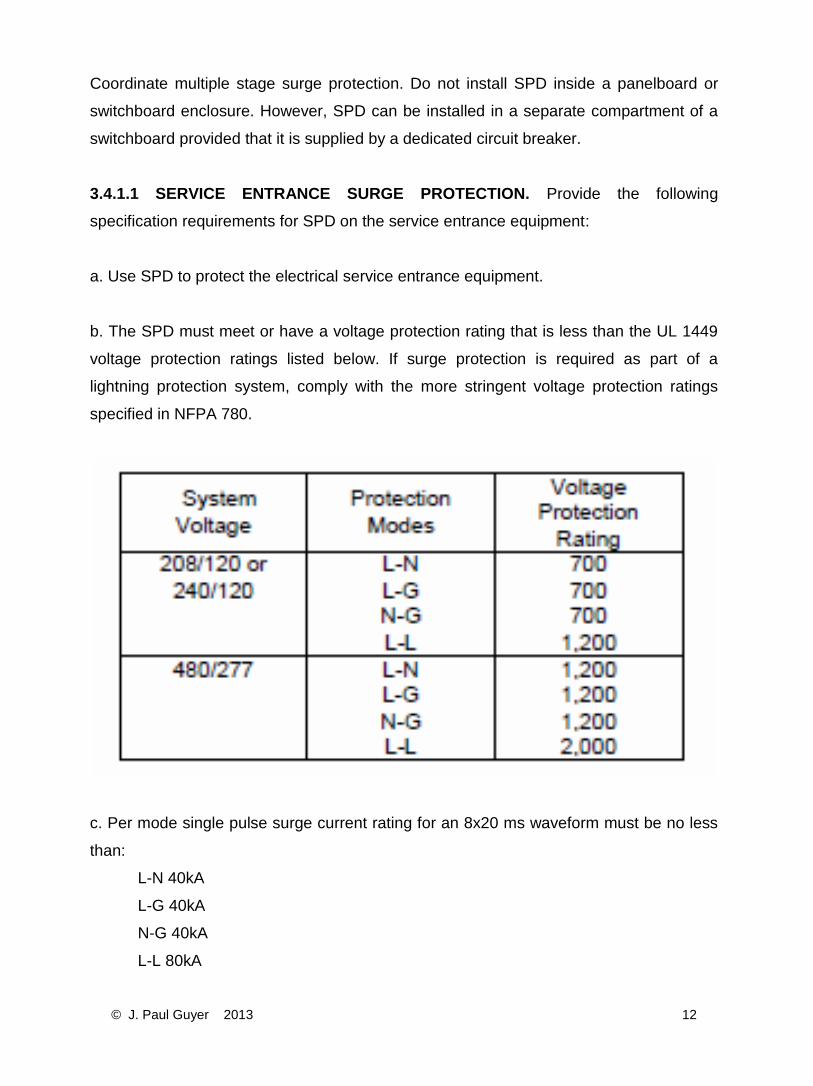
b. The SPD must meet or have a voltage protection rating that is less than the UL 1449
voltage protection ratings listed below. If surge protection is required as part of a
lightning protection system, comply with the more stringent voltage protection ratings
specified in NFPA 780.
c. Per mode single pulse surge current rating for an 8x20 ms waveform must be no less
than:
L-N 40kA
L-G 40kA
N-G 40kA
L-L 80kA
© J. Paul Guyer 2013 13
d. Protection Mode: Provide the following six modes (additional modes are permitted):
Line-to-line, Line-to-ground or line-to-neutral SPDs at grounded service entrances shall
be wired in a line-to-ground (L–G) or line-to-neutral (L–N) configuration. For services
without a neutral, SPD elements shall be connected line-to-ground (L–G).
e. MCOV for L-N and L-G modes of operation: 125% of nominal voltage for 240 volts and
below; 120% of nominal voltage above 240 volts to 480 volts.
f. Surge Life: Greater than 5000 surges of repetitive sequential IEEE C62.41 Category
C3 waveforms with less than 10% degradation of measured limiting voltage.
g. Listing: The total unit as installed must be UL 1283 and UL 1449 listed, and not merely
the components or modules.
h. Warranty: Not less than a 5-year warranty and include unlimited free replacements of
the unit if destroyed by lightning or other transients during the warranty period.
i. Diagnostics: Visual indication unit has malfunctioned or requires replacement. Provide
Form C dry contacts for remote monitoring.
3.4.1.2 BRANCH PANELBOARD SURGE PROTECTION. Provide the following
specification requirements for SPD on all the branch panelboards for facilities requiring
cascaded suppression system protection.
a. Use SPD to protect the distribution branch panelboards.
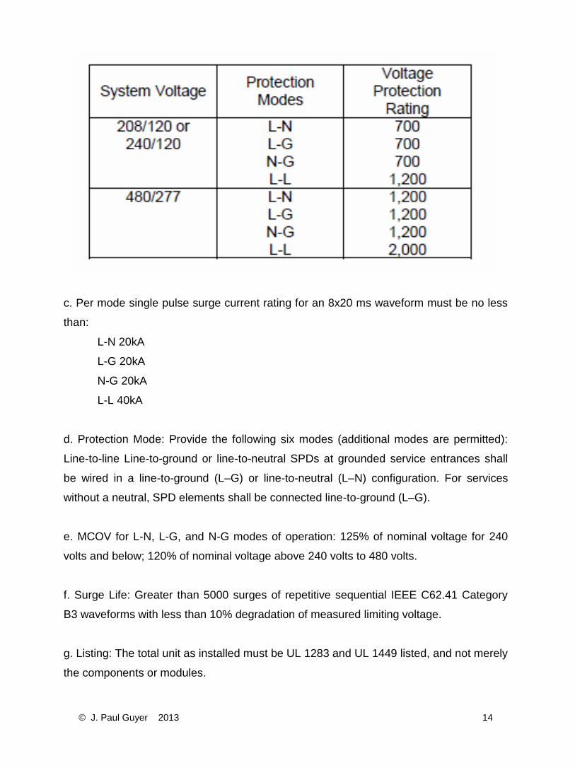
b. The SPD must meet or have a voltage protection rating that is less than the UL 1449
voltage protection ratings listed below.
© J. Paul Guyer 2013 14
c. Per mode single pulse surge current rating for an 8x20 ms waveform must be no less
than:
L-N 20kA
L-G 20kA
N-G 20kA
L-L 40kA
d. Protection Mode: Provide the following six modes (additional modes are permitted):
Line-to-line Line-to-ground or line-to-neutral SPDs at grounded service entrances shall
be wired in a line-to-ground (L–G) or line-to-neutral (L–N) configuration. For services
without a neutral, SPD elements shall be connected line-to-ground (L–G).
e. MCOV for L-N, L-G, and N-G modes of operation: 125% of nominal voltage for 240
volts and below; 120% of nominal voltage above 240 volts to 480 volts.
f. Surge Life: Greater than 5000 surges of repetitive sequential IEEE C62.41 Category
B3 waveforms with less than 10% degradation of measured limiting voltage.
g. Listing: The total unit as installed must be UL 1283 and UL 1449 listed, and not merely
the components or modules.
© J. Paul Guyer 2013 15
h. Warranty: Not less than a 5-year warranty and include unlimited free replacements of
the unit if destroyed by lightning or other transients during the warranty period.
i. Diagnostics: Visual indication unit has malfunctioned or requires replacement. Provide
Form C dry contacts for remote monitoring.
3.4.1.3 DWELLING UNITS SURGE PROTECTION. Install as close as practical to the
main breaker/lugs. All leads must be as short as possible, with no leads longer than 24 in
(610 mm). Provide protection in accordance with branch panelboard surge protection
criteria listed above.
3.4.2 SURGE PROTECTION FOR COMMUNICATIONS AND RELATED SYSTEMS.
Provide surge protection for the following systems, including related systems:
• Fire alarm systems.
• Telephone systems.
• Computer data circuits.
• Security systems.
• Television systems.
• Coaxial cable systems.
• Intercom systems.
• Electronic equipment data lines.
Surge protection equipment used for communications and related systems shall be UL
Listed or third-party verified and tested to UL 497A. If surge protection is required as part
of a lightning protection system, comply with the more stringent voltage protection ratings
specified in NFPA 780.
• Telephone communication interface circuit protection shall provide a minimum surge
current rating of 9,000A.
• Central office telephone line protection shall have multi-stage protection with a
minimum surge current rating of 4,000A.
© J. Paul Guyer 2013 16
• Intercom circuit protection shall have a minimum surge current rating of 9,000A.
Provide protection on points of entry and exit from separate buildings.
• Provide fire alarm and security alarm system loops and addressable circuits that
enter or leave separate buildings with a minimum of 9,000A surge current rating.
Annunciation shall be UL Listed or third-party verified and tested to UL 497B.
Protect coaxial lines at points of entry and exit from separate buildings. Single stage gas
discharge protectors can be used for less critical circuits. Multistage protectors utilizing a
gas discharge protector with solid-state secondary stages should be used to obtain lower
let-through voltages for more critical equipment.
3.4.3 ACCEPTANCE TESTS. Perform the following installation checks:
• Inspect for physical damage and compare nameplate data with drawings and
specifications.
• Verify that the surge protector rating is appropriate for the voltage.\2\ /2/
• Inspect for proper mounting and adequate clearances.
• Verify that the installation achieves the minimum possible lead lengths. Inspect
the wiring for loops or sharp bends that add to the overall inductance.
• Check tightness of connections by using a calibrated torque wrench. Refer to the
manufacturer’s instructions or Table 10-1 of International Electrical Testing
Association (NETA) ATS for the recommended torque.
• Check the ground lead on each device for individual attachment to the ground bus
or ground electrode.
• Perform insulation resistance tests in accordance with the manufacturer’s
instructions.
• For surge protectors with visual indications of proper operation (indicating lights),
verify that the surge protector displays normal operating characteristics.
• Record the date of installation.
3.5 METERING. Provide smart metering systems (e.g., with remote reading,
monitoring, or activation capabilities) in accordance with owner-specific criteria to comply
© J. Paul Guyer 2013 17
with requirements. Coordinate meters, system components, and meter locations to be
compatible with the owner’s central system.
3.6 RACEWAY AND WIRING.
3.6.1 WIRING DEVICES. Wiring devices and faceplate colors must match and be
consistent with the interior wall types and colors. Use grounding type wiring devices.
Outlet boxes must not be placed back to back. Provide a minimum of 12 inch (300 mm)
of separation between outlet boxes located on opposite sides on common walls.
3.6.1.1 SWITCHES. Toggle switches must be specification grade, quiet type, and rated
minimum 120/277V, 20A, totally enclosed with bodies of thermoplastic and/or thermoset
plastic and mounting strap with grounding screw. Use silver-cadmium contacts and one-
piece copper alloy contact arm. When specified, pilot lights must be integrally
constructed as a part of the switch's handle.
3.6.1.2 RECEPTACLES. Provide general purpose convenience outlets that are
specification grade, 20A, 120V, duplex. In addition to the location requirements specified
by NFPA 70, locate general purpose and dedicated (on an individual circuit) outlets in
accordance with the following:
a. Mechanical equipment: Provide receptacle within 25 ft (7.6 m) of mechanical
equipment on the interior and exterior of buildings.
b. Office, staff-support spaces, and other workstation locations: One receptacle for each
workstation with a minimum of one for every 10 ft (3 m) of wall space. When less than 10
ft (3 m) of wall at the floor line, provide a minimum of two receptacles spaced
appropriately to anticipate furniture relocations. Limit loads to a maximum of four (4)
workstations per 20A circuit.
c. Conference rooms and training rooms: One for every 12 ft (3.6 m) of wall space at the
floor line. Ensure one receptacle is located next to each voice/data outlet. Provide one
receptacle above the ceiling to support video projection device. Extend circuit to wall
© J. Paul Guyer 2013 18
location for connection to motorized screen. When it is expected that a conference room
table will be specifically dedicated to floor space in a conference room, locate a floor-
mounted receptacle under the table. This receptacle may be part of combination
power/communications outlet.
d. Provide power outlets throughout the building to serve all proposed equipment,
including government furnished equipment, and allow for future reconfiguration of
equipment layout. Provide power connections to all ancillary office equipment such as
printers, faxes, plotters, and shredders. Provide dedicated circuits where warranted.
e. In each telecommunications room provide a dedicated 20A circuit with a receptacle
adjacent to each rack or backboard for each of the following:
• CCTV for training systems
• CCSTV for security systems
• CATV
• Voice systems
• Data systems.
f. Provide dedicated receptacles as required throughout the facility for television
monitors. These outlets will typically be located at the ceiling level for wall mounted
television monitors. However, similar specialty equipment can share the same circuit.
g. Corridors: One every 50 ft (15 m) with a minimum of one per corridor.
h. Janitor’s closet and toilet rooms: One GFI receptacle per closet. Provide GFI
receptacles at counter height for each counter in toilets such that there is a minimum of
one outlet for each two sinks.
i. Space with counter tops: One for every 4 ft (1.2 m) of countertop, with a minimum of
one outlet. Provide GFI protection of outlets when located within 6 ft (1.8 m) of plumbing
fixtures.
© J. Paul Guyer 2013 19
j. Building exterior: One for each wall, GFI protected and weatherproof.
k. Kitchen non-residential: One for each 10 ft (3 m) of wall space at the floor line. Provide
GFI protection when located within 6 ft (1.8 m) of plumbing fixture.
l. Dwelling units, child development centers, and other child occupied spaces (including
toilets): Provide listed tamper-resistant receptacles.
m. All other rooms: One for every 25 ft (7.6 m) of wall space at the floor line. When 25 ft
(7.6 m) or less of wall at the floor line exists in a room, provide a minimum of two
receptacles spaced appropriately to anticipate furniture relocations.
n. Special purpose receptacles: Coordinate with the user to provide any special purpose
outlets required. Provide outlets to allow connection of equipment in special use rooms.
3.6.2 RACEWAY CRITERIA. Install all wiring in raceways unless specifically indicated
otherwise. Minimum permitted size conduit permitted is 1/2 in (16 mm). Provide an
insulated green equipment grounding conductor for all circuit(s) installed in raceways.
Conceal raceways above ceilings and in finished areas that have finished walls or
finished surfaces. Do not use electrical non-metallic tubing (ENT) or flexible non-metallic
tubing and associated fittings. The following summarizes approved raceway types and
their limitations of use:
• Galvanized Rigid Steel (GRS) Conduit. Specify GRS conduit \1\ where exposed to
weather, where subject to physical damage, and where exposed /1/ on exterior of
buildings.
• Intermediate Metal Conduit (IMC). IMC may be used in lieu of GRS as allowed by
NFPA 70.
• Electrical Metallic Tubing (EMT). Specify EMT for branch circuits and feeders
above suspended ceilings or exposed where not subject to physical damage. Do
not use EMT underground, encased in concrete, mortar or grout, in hazardous
© J. Paul Guyer 2013 20
locations, where exposed to physical damage, outdoors or in fire pump rooms.
Use die-cast compression connectors.
• Flexible Metal Conduit. Flexible metal conduit can be used, limited to 6-foot
length, for recessed and semirecessed lighting fixtures; for equipment subject to
vibration; and for motors other than pumps. Use liquidtight flexible metal conduit in
damp and wet locations and for pumps.
• Polyvinyl Chloride (PVC). Specify Schedule 40 PVC (minimum) for service
entrance conduits from the service utility to the substation or underground below
floor slabs. PVC is not approved for use when restrictions are stipulated in other
industry standards or UFCs for specific types of buildings such as medical
facilities.
• Surface Metal Raceways. Specify two-piece painted steel, totally enclosed, snap-
cover type, multiple outlet-type raceway only for shops, laboratories, and medical
facilities.
• Convert nonmetallic conduit, other than PVC Schedule 40 or 80, to plastic-coated
rigid, or IMC, steel conduit before rising through the floor slab.
Use surface metal raceways or multi-outlet assemblies only for building improvements or
renovations, or for applications where a variety of cord-and-plug connected equipment
will be utilized in a limited space, such as in some areas of medical facilities, shops, and
laboratories. Refer to TSEWG TP-8, Electrical Equipment Enclosures and Hazardous
Locations, at http://www.wbdg.org/ccb/browse_cat.php?o=29&c=248 for additional
information regarding equipment enclosures and hazardous locations.
3.6.3 CONDUCTORS. Conductors #6 AWG and smaller must be copper. Aluminum
conductors of equivalent ampacity can be used instead of copper for #4 AWG and larger
sizes. Branch circuit conductors, including power and lighting applications, will in no case
be less than #12 AWG. Branch circuit breakers shall be 20 amperes minimum, except
where lesser ratings are required for specific applications
© J. Paul Guyer 2013 21
3.7 LIGHTING. Lighting design is not part of this publication.
3.8 EMERGENCY GENERATORS.
3.8.1 APPLICATIONS. Emergency generators and related wiring systems are
authorized for use when needed to support mission-critical functions in the following
types of facilities and locations in accordance with paragraph 3.8.2:
• Medical treatment facilities
• Air transportation navigation aids and facilities
• Refrigerated storage rooms
• POL storage and dispensing facilities
• Critical utility plants and systems
• Civil engineer control centers
• Communication facilities and telephone exchanges
• Fire stations, including fire alarm, fire control, and radio equipment
• Critical computer automatic data processing facilities
• Airport traffic control towers
• Weather stations
• Surveillance and warning facilities
• Central control facilities
• Security lighting systems
• Law enforcement and security facilities
• Emergency operations centers (EOCs)
• Critical activity, property, and life support facilities at remote and not readily
accessible sites
• Industrial facilities that have noxious fumes requiring removal—provide power for
exhaust system only
3.8.2 LOAD ANALYSIS. Determine what loads or facilities need to continue to function
following a loss of normal power. Evaluate which loads must be uninterruptible, can
experience momentary power loss, or can experience a longer duration power loss.
© J. Paul Guyer 2013 22
Apply the following documents to determine which loads require backup power and
should be reviewed as part of a backup power need analysis:
• IEEE Std 446—provides a detailed discussion of how to evaluate the need for backup
power.
• NFPA 110—provides specific criteria for backup power systems.
• NFPA 111—establishes the NFPA requirements associated with backup power
systems.
3.8.3 SERVICE ENTRANCE DESIGN. If the facility has a permanently installed
emergency power source, provide a separate panel to supply only the loads requiring
emergency power. This panel will normally be supplied by the upstream main distribution
panel. Do not design the system in a manner that allows non-essential loads to be
carried by the emergency power source. If the facility is intended to have the capability
to connect portable emergency power generation, install a manually operated safety
switch designed for this purpose on the exterior of the facility. Alternatively, an approved
cable connection system can be installed with the cable connector located on the
exterior of the facility and connected on the interior of the facility to a normally open
safety switch or circuit breaker.
3.9 AUTOMATIC TRANSFER EQUIPMENT. Provide an open transition transfer
scheme unless the system requires paralleling with the utility. Closed transition transfer
is rarely required for backup power applications. Closed transition will require
coordination with the local utility and will require designing for the higher available short
circuit current of the combined parallel sources. Provide four-pole ATS designs to
ensure that the neutral is switched with the circuit. If allowed by the facility layout, locate
the transfer switch near the load. This increases system reliability by minimizing the
length of the run common to both power sources from the transfer switch to the load.
Design feeder routing with physical separation between the normal power feeders and
the emergency feeders. This minimizes the possibility that both power sources will be
simultaneously interrupted by a localized problem within the facility. Where possible, use
a greater number of small transfer switches rather than a lesser number of large transfer
switches. By this approach, failure of a single transfer switch should not affect the entire
© J. Paul Guyer 2013 23
facility. Include a fully rated break and load maintenance bypass switch in parallel with a
closed transition ATS. The ATS must be designed for maintenance and repair without
requiring shutdown of the associated system. Refer to NFPA 99 for any transfer switch
applications involving medical facilities. The following references provide additional
information regarding automatic transfer switches:
• EGSA 100S—contains classifications, applications and performance requirements
for transfer switches for emergency and standby transfer switches.
• IEEE Std 446—discusses ATS applications.
• NFPA 99—provides specific electrical requirements for medical facilities and
addresses transfer switch requirements in detail.
• NFPA 111—establishes the NFPA requirements for ATS designs.
• UL 1008—establishes ATS certification requirements and is a useful reference
source for ATS ratings.
3.10 STATIONARY BATTERIES AND BATTERY CHARGERS.
3.10.1 SELECTION. Use vented lead acid batteries preferentially for switchgear control
power and UPS applications. Batteries for switchgear or backup power applications
should be rated for general purpose, switchgear, or utility use. Batteries for UPS
applications should be rated for UPS or high-rate use. Nickel-cadmium batteries are
often more expensive than vented lead-acid batteries and should be considered primarily
for extreme temperature environments or engine-starting applications. Nickel-cadmium
batteries are preferred for engine starting applications because of their high-rate
discharge capability and their more predictable failure modes. As a general practice, do
not use a valve-regulated lead acid (VRLA) battery if a vented lead-acid battery will
satisfy the design and installation requirements. VRLA batteries have exhibited a shorter
service life than vented equivalents and have shown a tendency to fail without warning.
Refer to IEEE Std 1189 for additional information regarding the unique failure modes and
© J. Paul Guyer 2013 24
shorter service life of this battery type. VRLA batteries are allowed to be used in the
following types of applications:
• Installations with small footprints such that a vented battery with adequate power
density will not fit within the available space.
• Locations in which the consequences of electrolyte leakage cannot be allowed. UPS
systems are often located in areas that necessitate the use of a VRLA battery.
Do not use VRLA batteries in the following types of applications:
• Unregulated environments that can experience abnormally high and low
temperatures.
• Unmonitored locations that seldom receive periodic maintenance checks. VRLA
batteries have shown a tendency to fail within only a few years after installation.
• Critical applications, unless the installation location requires the features available
only in a VRLA battery.
Apply the following service life for life-cycle cost comparisons of stationary batteries:
• Small VRLA batteries – 3 years.
• Large VRLA batteries – 7 years.
• Small vented lead acid batteries – 10 years.
• Large vented lead acid batteries – 15 years.
• Nickel-cadmium batteries – 15 years.
3.10.2 BATTERY AREAS AND BATTERY RACKS. Comply with owner requirements.
3.10.3 INSTALLATION DESIGN.
© J. Paul Guyer 2013 25
3.10.3.1 INDUSTRY STANDARDS. Review the following IEEE standards, as applicable
for the battery type, prior to the installation:
• IEEE Std 450—provides maintenance and test criteria for vented lead acid
batteries.
• IEEE Std 484—provides installation criteria for vented lead acid batteries.
• IEEE Std 485—defines battery sizing requirements for lead acid batteries.
• IEEE Std 1106—provides maintenance and test criteria for nickel cadmium
batteries.
• IEEE Std 1115—defines battery sizing requirements for nickel cadmium batteries.
• IEEE Std 1184—provides application and sizing criteria for UPS applications.
• IEEE Std 1187—provides installation criteria for valve-regulated lead acid
batteries.
• IEEE Std 1188—provides maintenance and test criteria for valve-regulated lead
acid batteries.
• IEEE Std 1189—explains application limitations for valve-regulated lead acid
batteries.
3.10.3.2 DESIGN REQUIREMENTS. Size the battery in accordance with IEEE Std 485,
IEEE Std 1115, or IEEE Std 1184 as appropriate for the selected battery type and
application.
3.10.3.3 INSTALLATION REQUIREMENTS. Design and install the battery in
accordance with IEEE Std 484, IEEE Std 1187, or IEEE Std 1106 as appropriate for the
© J. Paul Guyer 2013 26
selected battery type. Refer to the above industry standards and NETA ATS for
acceptance test criteria.
3.10.4 BATTERY CHARGERS. Use single-phase chargers for smaller applications.
Rate single-phase battery chargers for 240V single phase, unless only 120V is available.
Use three-phase chargers if the charger’s DC output current rating will be greater than
75A. Unless the battery has specific requirements to the contrary, all chargers should be
of the constant voltage type.
3.10.5 BATTERY PROTECTION. Install a circuit breaker or fused protection device as
close to the battery as possible. Provide overcurrent protection for each string in a
parallel battery system. Refer to IEEE Std 1375 for additional guidance.
3.11 GROUNDING, BONDING, AND STATIC PROTECTION. Comply with NFPA 70 for
grounding and bonding requirements.
3.11.1 GROUND RODS. Ground rod composition, minimum spacing requirements and
connections shall conform to the requirements of NFPA 70 Section 250 except that
minimum length dimensions shall be 10 feet (3.0 m) in length and ¾ inch (19 mm)
diameter. Ground rods shall be copper-clad steel, solid copper, or stainless steel. All
connections to ground rods below ground level must be by exothermic weld connection
or with a high compression connection using a hydraulic or electric compression tool to
provide the correct circumferential pressure. Accessible connections above ground level
and in test wells can be accomplished by clamping. Spacing for driving additional
grounds must be a minimum of 10 ft (3.0 m). Bond these driven electrodes together with
a minimum of 4 AWG soft drawn bare copper wire buried to a depth of at least 12 in (300
mm). Install ground rods (and ground ring, if applicable) 3 ft to 8 ft (0.9 m to 2.4 m)
beyond the perimeter of the building foundation and at least beyond the drip line for the
facility.
3.11.2 GROUND RINGS. Provide a ground ring (counterpoise) for facilities with
sensitive electronic equipment or other applications when identified by project
requirements. A ground ring shall have at least two ground rods located diagonally at
© J. Paul Guyer 2013 27
opposite corners. When required by a specific activity or facility, provide a ground rod at
each change in direction of the ground ring and install test wells for at least two of the
corner ground rods to allow for testing of the system. Assemble test wells with bolted
connections to facilitate future testing.
3.11.3 COMMUNICATION-ELECTRONICS FACILITIES. Provide grounding electrode
systems for communications-electronics (c-e) facilities in accordance with owner
requirements.
3.11.4 STATIC ELECTRICITY PROTECTION. Comply with owner requirements for
static protection.
3.12 LIGHTNING PROTECTION SYSTEMS. Provide lightning protection systems in
accordance with best practices and owner requirements.
3.13 400-HERTZ DISTRIBUTION SYSTEMS. Design 400 hertz power systems in
accordance with best practices and owner requirements.
3.14 270-VOLT DC DISTRIBUTION SYSTEMS. System design requirements are not
part of this publication.
3.15 POWER FACTOR CORRECTION. The power factor within a facility is normally
0.9 lagging or greater; therefore, power factor correction is not routinely required for
interior electrical systems.
3.16 POWER QUALITY. Design secondary electrical systems to mitigate the harmonic
effects of non-linear loads as a result of connections to electronic loads, including
computer work stations, file servers, UPS, and electronic ballasts.
3.17 SYSTEMS FURNITURE. When systems furniture is utilized, the electrical
engineer, the architect, and the interior designer must coordinate during the design
process. Systems furniture is typically specified and ordered when construction is
nearing completion; therefore, if proper coordination has not occurred earlier in the
© J. Paul Guyer 2013 28
design process, field interface problems will occur. Systems furniture is pre-wired to a
wiring harness. Unless specified otherwise, select a standard wiring harness that meets
one of the following configurations:
• 5-wire harness consisting of 3 circuit conductors, 1 oversized neutral conductor
and 1 equipment grounding conductor.
• 8-wire harness consisting of 4 circuit conductors, 1 oversized neutral conductor, 1
full sized neutral conductor and 2 separate equipment grounding conductors.
Serve 5-wire harnesses with 3 separate circuits and 8-wire harnesses with 4 separate
circuits. Provide oversized neutrals to match the harness configuration and balance
loads between circuits and phases. A single circuit must not serve more than 4 cubicles
under any circumstances.
© J. Paul Guyer 2013 29
4. GLOSSARY
Abbreviations and Acronyms:
A—Amperes
AC—Alternating Current
AHJ—Authority Having Jurisdiction
ANSI—American National Standards Institute
ASD—Adjustable Speed Drive
ATS—Automatic Transfer Switch
AWG—American Wire Gauge
CCTV—Closed Circuit Television
CATV—Cable Television
CFR—Code of Federal Regulations
COPS—Critical Operations Power System /1/
DC—Direct Current
DDC—Direct Digital Control
EGSA—Electrical Generating Systems Association
EMT—Electrical Metallic Tubing
ENT—Electrical Non-Metallic Tubing
FE—Full Electric
ft—Feet
GRS—Galvanized Rigid Steel
HID—High Intensity Discharge
HVAC—Heating, Ventilating, and Air Conditioning
© J. Paul Guyer 2013 30
Hz—Hertz
IEEE—formerly Institute of Electrical and Electronics Engineers
IMC—Intermediate Metal Conduit
kA—Kilo-Amperes
kVA—Kilo-Volt-Amperes
kW—Kilowatt
m—Meter
MCC—Motor Control Center
MCOV—Maximum Continuous Overvoltage Rating
MI—Mineral Insulated
MOV—Metal Oxide Varistor
mm—Millimeter
MVA—Megavolts-Ampere
NEC—National Electrical Code
NEMA—National Electrical Manufacturers Association
NETA—International Electrical Testing Association
NFPA—National Fire Protection Association
OSHA—Occupational Safety and Health Administration
PVC—Polyvinyl Chloride
RMS—Root-Mean-Square
SPD—Surge Protective Devices /1/
SWD—Switching Duty
TVSS—Transient Voltage Surge Suppressor
UFC—Unified Facilities Criteria
© J. Paul Guyer 2013 31
UL—Underwriters Laboratories
UPS—Uninterruptible Power Supply
V—Volts
VFD—Variable Frequency Drive (see ASD)
VRLA—Valve-Regulated Lead Acid
Terms:
Note: The terms listed here are provided for clarification of the design criteria provided in
this publication. Refer to IEEE Std 100 for additional electrical-related definitions.
Automatic Transfer Switch (ATS)—A switch designed to sense the loss of one power
source and automatically transfers the load to another source of power.
Branch Circuit—The circuit conductors and components between the final overcurrent
device protecting the circuit and the equipment.
Closed Transition Switch—Transfer switch that provides a momentary paralleling of
both power sources during a transfer in either direction. The closed transition is possible
only when the sources are properly interfaced and synchronized.
Existing Facility—A facility is existing if changes to be made are cosmetic or minor in
nature.
Harmonic—A sinusoidal component of a periodic wave or quantity having a frequency
that is an integral multiple of the fundamental frequency.
Linear Load—An electrical load device that presents an essentially constant load
impedance to the power source throughout the cycle of applied voltage in steady-state
operation.
Listed—Applies to equipment or materials included in a list published by an organization
acceptable to the authority having jurisdiction. The organization periodically inspects
production and certifies that the items meet appropriate standards or tests as suitable for
a specific use.
Low Voltage System—An electrical system having a maximum root-mean-square (rms)
voltage of less than 1,000 volts.
© J. Paul Guyer 2013 32
Medium Voltage System—An electrical system having a maximum RMS AC voltage of
1,000 volts to 34.5 kV. Some documents such as ANSI C84.1 define the medium voltage
upper limit as 100 kV, but this definition is inappropriate for facility applications.
Molded Case Circuit Breaker—A low voltage circuit breaker assembled as an integral
unit in an enclosed housing of insulating material. It is designed to open and close by
nonautomatic means, and to open a circuit automatically on a predetermined
overcurrent, without damage to itself, when applied properly within its rating.
Motor Control Center—A piece of equipment that centralizes motor starters, associated
equipment, bus and wiring in one continuous enclosed assembly.
New Construction—A facility is considered new if changes to be made are more than
cosmetic or minor, such as major renovations, additions, or new facilities.
Nonlinear Load—A steady state electrical load that draws current discontinuously or
has the impedance vary throughout the input ac voltage waveform cycle. Alternatively, a
load that draws a nonsinusoidal current when supplied by a sinusoidal voltage source.
Power Quality—The concept of powering and grounding sensitive equipment in a
manner that is suitable to the operation of that equipment.
Service Voltage—Voltage at the facility service entrance location.
Short Circuit—An abnormal condition (including an arc) of relatively low impedance,
whether made accidentally or intentionally, between two points of different potential.
Surge Protector—A device composed of any combination of linear or nonlinear circuit
elements and intended for limiting surge voltages on equipment by diverting or limiting
surge current; it prevents continued flow of current and is capable of repeating these
functions as specified.
Transfer Switch—A device for transferring one or more load conductor connections
from one power source to another.
Uninterruptible Power Supply System—A system that converts unregulated input
power to voltage and frequency controlled filtered AC power that continues without
interruption even with the deterioration of the input AC power.
Utilization Voltage—The voltage at the line terminals of utilization equipment