An Introduction to Carrier Aggregation Testing...LTE to LTE-A while maintaining service to legacy...
23
An Introduction to Carrier Aggregation Testing Meeting the challenge of high quality mobile services
Transcript of An Introduction to Carrier Aggregation Testing...LTE to LTE-A while maintaining service to legacy...
An Introduction to Carrier Aggregation TestingMeeting the challenge of high quality mobile services
Content 1.0 Carrier Aggregation as a part of LTE-A 4
2.0 Basics on 3GPP Specifications Related to Carrier Aggregation 5
2.1 Component Carrier Combination and Bands 5
2.2 Deployment Scenarios 8
3.0 Carrier Aggregation Design Principles 9
3.1 General Rules 9
3.2 Higher Layer Aspects 9
3.3 Main Physical Layer Aspects 10
3.4 Some Further Enhancements 12
4.0 Carrier Aggregation Testing with TEMS Tools 13
4.1 Carrier Aggregation Deployment Monitoring 13
4.2 Network Optimization 17
4.3 Troubleshooting 20
5.0 Conclusions 22
6.0 References 23

WHITE PAPER
4
1.0 Carrier Aggregation as part of LTE-AMeeting the challenge of high quality mobile
services
Today’s mobile data services explosion imposes
challenges on operators to provide high quality services
for mobile applications in a cost effective manner. To
support operators, the ITU initiated a global standard
initiative for IMT Advanced systems which are required to
meet enhanced user and service demands with peak data
rate targets of 100 Mb/sec for high mobility and 1 Gb/sec
for low mobility. In addition, IMT-A systems have to have
key features such as functional commonality, intersystem
operability, global roaming and user friendly applications.
In November 2010, LTE-A was ratified as the technology to
meet all IMT-A requirements. Therefore, LTE-A, which is first
released with Release 10, builds on 3GPP specifications
for LTE Releases 8 and 9. To satisfy the peak data rates,
LTE-A needs to minimally support bandwidths of up to 100
MHz. The ability to achieve higher data rates is constrained
by spectrum fragmentation and, as large portions of
contiguous spectrum are rare, the bandwidth increase can
be ensured only by the aggregation of multiple component
carriers of smaller bandwidths of different frequencies, and
this technique is called carrier aggregation (hereinafter
referred to as simply CA). CA can be used for both Time-
division duplexing (TDD) and Frequency-division duplexing
(FDD).
CA provides advantages in addition to faster data rates,
such as spectrum efficiency, deployment flexibility, and
backward compatibility. The spectrum can be more
efficiently utilized by aggregating non-continuous
carriers. Proper utilization of different carriers can support
various deployment scenarios for both homogenous and
heterogeneous networks. Each component carrier is LTE
compatible, thereby allowing operators to migrate from
LTE to LTE-A while maintaining service to legacy LTE users.
In addition, re-utilization of the LTE design on each of the
component carriers minimizes the implementation and
specification efforts. CA provides support for several uses
cases, starting with Release 10, which was frozen by the
3GPP in April of 2011:
1. CA allows operators with higher licensed frequency
spectrum like 3.5 GHz to provide higher peak rates
and capacity without being restricted by the Release 8
and 9 20 MHz limit. In the lower frequency bandwidths
like 700 MHz, where spectrum is licensed in much
narrower blocks like 6 MHz in the U.S., CA enables
operators to pool their spectrum resources together
(up to 100 MHz total) within the same band or across
different bands to achieve higher peak rates and
capacity.
2. CA allows operators to provide multiple services
simultaneously over multiple carriers.
3. CA can improve network efficiency and user
performance by dynamically allocating traffic
across the entire available spectrum. This can be
implemented using CA capable devices that report
channel quality for carriers across a wide spectrum.
This improves resource allocation and handover in
heterogeneous networks where both the number
of carriers and the carrier transmit powers can vary
significantly across sites. Both the macro and the small
cells (pico/femto) can transmit aggregated multiple
carriers and dynamically allocate resources across
carriers.
4. CA already supports cross carrier scheduling that
can mitigate the control channel intercell interference
resulting from spectrum sharing between macrocells
and pico/femto cells.
CA provides advantages in addition to faster data rates, such as spectrum efficiency, deployment flexibility, and backward compatibility. The spectrum can be more efficiently utilized by aggregating non-continuous carriers. Proper utilization of different carriers can support various deployment scenarios for both homogenous and heterogeneous networks.
WHITE PAPER
5
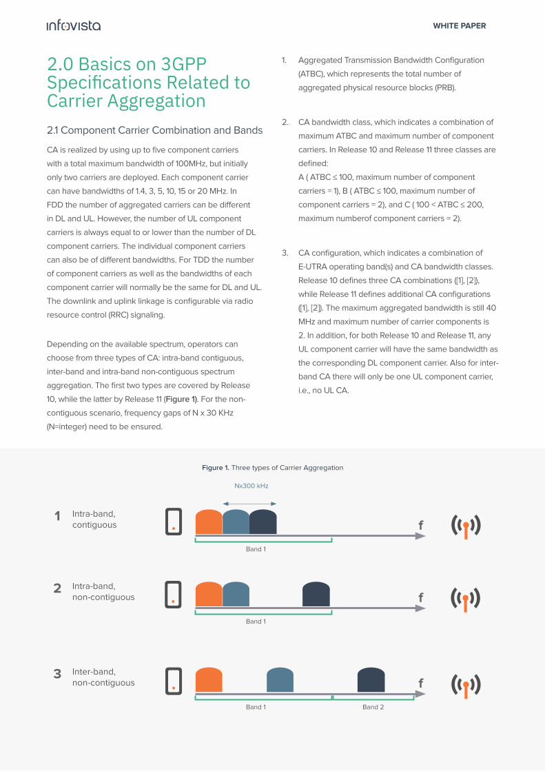
Figure 1. Three types of Carrier Aggregation
2.0 Basics on 3GPP Specifications Related to Carrier Aggregation2.1 Component Carrier Combination and Bands
CA is realized by using up to five component carriers
with a total maximum bandwidth of 100MHz, but initially
only two carriers are deployed. Each component carrier
can have bandwidths of 1.4, 3, 5, 10, 15 or 20 MHz. In
FDD the number of aggregated carriers can be different
in DL and UL. However, the number of UL component
carriers is always equal to or lower than the number of DL
component carriers. The individual component carriers
can also be of different bandwidths. For TDD the number
of component carriers as well as the bandwidths of each
component carrier will normally be the same for DL and UL.
The downlink and uplink linkage is configurable via radio
resource control (RRC) signaling.
Depending on the available spectrum, operators can
choose from three types of CA: intra-band contiguous,
inter-band and intra-band non-contiguous spectrum
aggregation. The first two types are covered by Release
10, while the latter by Release 11 (Figure 1). For the non-
contiguous scenario, frequency gaps of N x 30 KHz
(N=integer) need to be ensured.
1. Aggregated Transmission Bandwidth Configuration
(ATBC), which represents the total number of
aggregated physical resource blocks (PRB).
2. CA bandwidth class, which indicates a combination of
maximum ATBC and maximum number of component
carriers. In Release 10 and Release 11 three classes are
defined:
A ( ATBC ≤ 100, maximum number of component
carriers = 1), B ( ATBC ≤ 100, maximum number of
component carriers = 2), and C ( 100 < ATBC ≤ 200,
maximum numberof component carriers = 2).
3. CA configuration, which indicates a combination of
E-UTRA operating band(s) and CA bandwidth classes.
Release 10 defines three CA combinations ([1], [2]),
while Release 11 defines additional CA configurations
([1], [2]). The maximum aggregated bandwidth is still 40
MHz and maximum number of carrier components is
2. In addition, for both Release 10 and Release 11, any
UL component carrier will have the same bandwidth as
the corresponding DL component carrier. Also for inter-
band CA there will only be one UL component carrier,
i.e., no UL CA.
Intra-band, contiguous
Band 1
Nx300 kHz
f1
Intra-band, non-contiguous
Band 1
f2
Inter-band, non-contiguous
Band 1
f3
Band 2
WHITE PAPER
6
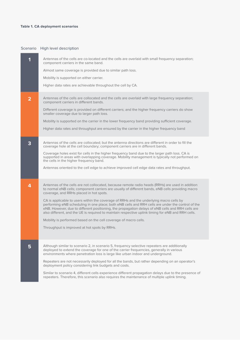
Table 1. CA deployment scenarios
Scenario High level description
Antennas of the cells are co-located and the cells are overlaid with small frequency separation; component carriers in the same band.
Almost same coverage is provided due to similar path loss.
Mobility is supported on either carrier.
Higher data rates are achievable throughout the cell by CA.
Antennas of the cells are collocated and the cells are overlaid with large frequency separation; component carriers in different bands.
Different coverage is provided on different carriers; and the higher frequency carriers do show smaller coverage due to larger path loss.
Mobility is supported on the carrier in the lower frequency band providing sufficient coverage.
Higher data rates and throughput are ensured by the carrier in the higher frequency band
Antennas of the cells are collocated; but the antenna directions are different in order to fill the coverage hole at the cell boundary; component carriers are in different bands.
Coverage holes exist for cells in the higher frequency band due to the larger path loss. CA is supported in areas with overlapping coverage. Mobility management is typically not performed on the cells in the higher frequency band.
Antennas oriented to the cell edge to achieve improved cell edge data rates and throughput.
Antennas of the cells are not collocated, because remote radio heads (RRHs) are used in addition to normal eNB cells; component carriers are usually of different bands, eNB cells providing macro coverage, and RRHs placed in hot spots.
CA is applicable to users within the coverage of RRHs and the underlying macro cells by performing eNB scheduling in one place; both eNB cells and RRH cells are under the control of the eNB. However, due to different positioning, the propagation delays of eNB cells and RRH cells are also different, and the UE is required to maintain respective uplink timing for eNB and RRH cells.
Mobility is performed based on the cell coverage of macro cells.
Throughput is improved at hot spots by RRHs.
Although similar to scenario 2, in scenario 5, frequency selective repeaters are additionally deployed to extend the coverage for one of the carrier frequencies, generally in various environments where penetration loss is large like urban indoor and underground.
Repeaters are not necessarily deployed for all the bands, but rather depending on an operator’s deployment policy considering link budgets and costs.
Similar to scenario 4, different cells experience different propagation delays due to the presence of repeaters. Therefore, this scenario also requires the maintenance of multiple uplink timing.
1
2
3
4
5

WHITE PAPER
7
Figure 2. CA deployment scenarios
eNodeB
eNodeB
eNodeB
eNodeB
RRH
RRH
RRH
RRH
eNodeBRepeater
Component Carrier 1
Component Carrier 2
3Scenario
1Scenario
2Scenario
4Scenario
5Scenario

WHITE PAPER
8
Based on real world spectrum allocation and operators’
need, 3GPP RAN 4 has been working on 14 different band
combinations, most of which aggregate two carriers to
achieve up to 40MHz total bandwidth in both downlink and
uplink. Some of the operators’ combinations of interest are
presented in [2].
Based on the demand to support the asymmetric
downlink heavy user traffic pattern, the Release 10 and
11 RF specification work has been prioritized to focus on
downlink CA, while the work on uplink CA is expected to
follow in Release 12.
2.2 Deployment Scenarios
CA deployment scenarios aim to improve data rates
for users within overlapped areas of cells and depend
largely on the operator’s needs. For efficient deployment,
operators take into consideration various factors, such as
spectrum allocation, urban/suburban/rural areas antenna
direction and location, hot spots, and the presence of
frequency-selective repeaters.
Table 1 and Figure 2 describe the possible deployment
scenarios [3], [4].
The downlink CA operation does not affect uplink timing
in any of the scenarios described in Table 1. Therefore,
downlink CA is already covered starting with Release 10,
while the uplink case has been deferred to Release 11.
Backward compatibility is required for smooth migration and maximal reuse of the LTE Releases 8 and 9 design. Each component carrier in 3GPP LTE-A should be accessible by LTE Releases 8 and 9 user equipment (UE). Therefore, the complete set of Releases 8 and 9 downlink physical channels and signals are transmitted on each component’s carrier based on the LTE Releases 8 and 9 procedures, including system information, synchronization and reference signals, and control channels.
WHITE PAPER
9
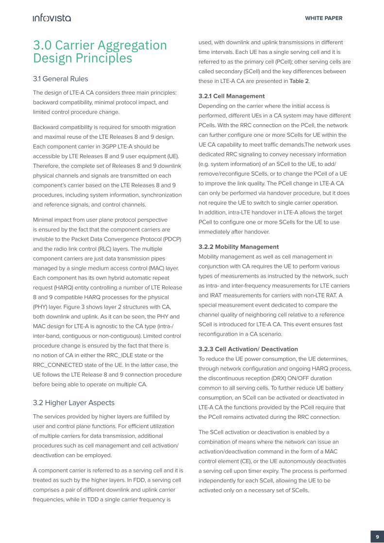
3.0 Carrier Aggregation Design Principles3.1 General Rules
The design of LTE-A CA considers three main principles:
backward compatibility, minimal protocol impact, and
limited control procedure change.
Backward compatibility is required for smooth migration
and maximal reuse of the LTE Releases 8 and 9 design.
Each component carrier in 3GPP LTE-A should be
accessible by LTE Releases 8 and 9 user equipment (UE).
Therefore, the complete set of Releases 8 and 9 downlink
physical channels and signals are transmitted on each
component’s carrier based on the LTE Releases 8 and 9
procedures, including system information, synchronization
and reference signals, and control channels.
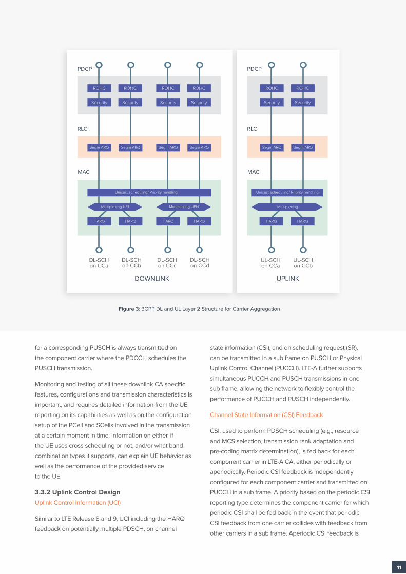
Minimal impact from user plane protocol perspective
is ensured by the fact that the component carriers are
invisible to the Packet Data Convergence Protocol (PDCP)
and the radio link control (RLC) layers. The multiple
component carriers are just data transmission pipes
managed by a single medium access control (MAC) layer.
Each component has its own hybrid automatic repeat
request (HARQ) entity controlling a number of LTE Release
8 and 9 compatible HARQ processes for the physical
(PHY) layer. Figure 3 shows layer 2 structures with CA,
both downlink and uplink. As it can be seen, the PHY and
MAC design for LTE-A is agnostic to the CA type (intra-/
inter-band, contiguous or non-contiguous). Limited control
procedure change is ensured by the fact that there is
no notion of CA in either the RRC_IDLE state or the
RRC_CONNECTED state of the UE. In the latter case, the
UE follows the LTE Release 8 and 9 connection procedure
before being able to operate on multiple CA.
3.2 Higher Layer Aspects
The services provided by higher layers are fulfilled by
user and control plane functions. For efficient utilization
of multiple carriers for data transmission, additional
procedures such as cell management and cell activation/
deactivation can be employed.
A component carrier is referred to as a serving cell and it is
treated as such by the higher layers. In FDD, a serving cell
comprises a pair of different downlink and uplink carrier
frequencies, while in TDD a single carrier frequency is
used, with downlink and uplink transmissions in different
time intervals. Each UE has a single serving cell and it is
referred to as the primary cell (PCell); other serving cells are
called secondary (SCell) and the key differences between
these in LTE-A CA are presented in Table 2.
3.2.1 Cell Management
Depending on the carrier where the initial access is
performed, different UEs in a CA system may have different
PCells. With the RRC connection on the PCell, the network
can further configure one or more SCells for UE within the
UE CA capability to meet traffic demands.The network uses
dedicated RRC signaling to convey necessary information
(e.g. system information) of an SCell to the UE, to add/
remove/reconfigure SCells, or to change the PCell of a UE
to improve the link quality. The PCell change in LTE-A CA
can only be performed via handover procedure, but it does
not require the UE to switch to single carrier operation.
In addition, intra-LTE handover in LTE-A allows the target
PCell to configure one or more SCells for the UE to use
immediately after handover.
3.2.2 Mobility Management
Mobility management as well as cell management in
conjunction with CA requires the UE to perform various
types of measurements as instructed by the network, such
as intra- and inter-frequency measurements for LTE carriers
and IRAT measurements for carriers with non-LTE RAT. A
special measurement event dedicated to compare the
channel quality of neighboring cell relative to a reference
SCell is introduced for LTE-A CA. This event ensures fast
reconfiguration in a CA scenario.
3.2.3 Cell Activation/ Deactivation
To reduce the UE power consumption, the UE determines,
through network configuration and ongoing HARQ process,
the discontinuous reception (DRX) ON/OFF duration
common to all serving cells. To further reduce UE battery
consumption, an SCell can be activated or deactivated in
LTE-A CA the functions provided by the PCell require that
the PCell remains activated during the RRC connection.
The SCell activation or deactivation is enabled by a
combination of means where the network can issue an
activation/deactivation command in the form of a MAC
control element (CE), or the UE autonomously deactivates
a serving cell upon timer expiry. The process is performed
independently for each SCell, allowing the UE to be
activated only on a necessary set of SCells.
WHITE PAPER
10
To understand the impact of the CA benefits as well as
its operability, it is important to monitor intra-handover
information (before and after), UE measurement events
related to CQI of neighboring cells in relationship to a
reference SCell, as well as cell activation/deactivation
events and processes.
3.3 Main Physical Layer Aspects
LTE-A CA largely inherits the LTE Release 8 and 9 data
transmission procedure per component carrier [6], [7], [8],
including the multiple access scheme, modulation and
channel coding. In addition to those, starting with Release
10 additional UEfunctionalities aimed at CA support are
introduced.
These new capabilities refer to: data transmission over
two clusters of contiguous bandwidth in the same carrier,
simultaneous transmission of a control channel and a
data channel in the PCell, data transmission from multiple
antennas with spatial multiplexing, and improved design
of downlink and uplink control to efficiently support data
transmission. The latter represents the core of the physical
layer design for CA. Some of the downlink and uplink
improved designs are discussed in this section. Some
testing requirements are also pointed out.
3.3.1 Downlink Control Design
Physical Downlink Control Channel (PDCCH)
PDCCH provides information on resource allocation,
modulation and coding scheme (MSC), and other related
parameters for downlink (Physical Downlink Shared
Channel, PDSCH) and uplink (Physical Uplink Shared
Channel, PUSCH) data transmission. In LTE-A, CA allows
the configuration of each component carrier to transmit
PDCCH scheduling of a PDSCH on the same carrier
frequency and PDCCH scheduling of a PUSCH on a linked
UL carrier frequency where the linkage of the DL and UL
carriers is conveyed as system information. A new field,
Carrier Indicator Field (CIF), which is delivered through the
PDCCH, indicates the target component carrier where the
allocated radio resources exist. In addition, PDCCH on a
component carrier can be configured to schedule PDSCH
and PUSCH transmissions on other component carrier by
means of cross carrier scheduling. There are three benefits
of this CA feature:
• It is effective in a HetNet environment, where
neighboring cell interference alters the PDCCH signals
and radio resource allocation for the interfered cell
may not be possible. Cross carrier scheduling solves
the problem because the eNB can configure cells
other than the interfered cell for PDCCH transmission.
• It improves the scheduling flexibility of the eNB, in
the sense that the eNB has multiple DL component
carriers’ options for the transmission of the resource
allocation information.
• It reduces the processing burden of the UE’s PDCCH
blind decoding because using cross carrier scheduling
allows the UE to monitor a smaller number of DL
component carriers rather than all of the configured DL
component carriers.
PDCCH Search Space
A PDCCH search space is monitored by all UEs only in
their respective PCell for receiving system, paging, power
control and random access related information. In addition,
each UE has its own specific PDCCH search space which
is a function of the UE’s radio network temporary identifier
(RNTI). Since the same set of resources for PDCCH
transmission is shared, a PDCCH to a UE may not be
transmitted due to at least partial overlapping with PDCCH
to another UE, creating PDCCH blocking. To maintain the
same level of blocking probability as in Release 8 and 9,
LTE-A UE monitors one UE-specific PDCCH search space
for each activated component carrier. If cross carrier
scheduling is used, then the UE-specific PDCCH search
space is defined by a combination of the UE’s RNTI and the
serving cell index [8].
Physical Control Format Indicator Channel (PCFICH)
PCFICH transmitted in each sub frame conveys the control
format indicator (CFI) field which indicates the number of
OFDM symbols carrying control information in the sub
frame and which is decoded by the UE to determine the
starting OFDM symbol used for PDSCH transmission. The
UE is required to decode the CFI for PDSCH scheduled
by PDCCH on the same component carrier, however, in
cross carrier allocation scenarios, the UE is not required to
decode the CFI for the PDSCH on the aggregated CC as
the starting OFDM is communicated by higher layers.
Physical HARQ Indicator Channel (PHICH)
PHICH carrying the HARQ feedback information associated
with the PUSCH transmission is sent in LTE-A CA similar to
LTE Release 8 and 9, on the component carrier where the
PDCCH schedules the PUSCH transmission. The PHICH
WHITE PAPER
11
for a corresponding PUSCH is always transmitted on
the component carrier where the PDCCH schedules the
PUSCH transmission.
Monitoring and testing of all these downlink CA specific
features, configurations and transmission characteristics is
important, and requires detailed information from the UE
reporting on its capabilities as well as on the configuration
setup of the PCell and SCells involved in the transmission
at a certain moment in time. Information on either, if
the UE uses cross scheduling or not, and/or what band
combination types it supports, can explain UE behavior as
well as the performance of the provided service
to the UE.
3.3.2 Uplink Control Design
Uplink Control Information (UCI)
Similar to LTE Release 8 and 9, UCI including the HARQ
feedback on potentially multiple PDSCH, on channel
state information (CSI), and on scheduling request (SR),
can be transmitted in a sub frame on PUSCH or Physical
Uplink Control Channel (PUCCH). LTE-A further supports
simultaneous PUCCH and PUSCH transmissions in one
sub frame, allowing the network to flexibly control the
performance of PUCCH and PUSCH independently.
Channel State Information (CSI) Feedback
CSI, used to perform PDSCH scheduling (e.g., resource
and MCS selection, transmission rank adaptation and
pre-coding matrix determination), is fed back for each
component carrier in LTE-A CA, either periodically or
aperiodically. Periodic CSI feedback is independently
configured for each component carrier and transmitted on
PUCCH in a sub frame. A priority based on the periodic CSI
reporting type determines the component carrier for which
periodic CSI shall be fed back in the event that periodic
CSI feedback from one carrier collides with feedback from
other carriers in a sub frame. Aperiodic CSI feedback is
Figure 3: 3GPP DL and UL Layer 2 Structure for Carrier Aggregation
ROHC
Security
Segm ARQ
Unicast scheduling/ Priority handling
ROHC
Security
Segm ARQ
ROHC
Security
Segm ARQ
ROHC
Security
Segm ARQ
ROHC
Security
Segm ARQ
ROHC
Security
Segm ARQ
Unicast scheduling/ Priority handling
Multiplexing UE1
HARQHARQ HARQ HARQ
Multiplexing UEN
HARQ HARQ
Multiplexing
DL-SCH on CCa
DL-SCH on CCb
DL-SCH on CCc
DL-SCH on CCd
UL-SCH on CCa
UL-SCH on CCb
DOWNLINK UPLINK
PDCP
RLC
MAC
PDCP
RLC
MAC
WHITE PAPER
12
transmitted on PUSCH and LTE-A CA can support single or
multiple component carriers in a sub frame in order for the
network to balance feedback overhead.
Uplink Power Control
The uplink power control mechanism is used by the UE
to determine a PUSCH or PUCCH transmission power
[8], which ensures that the respective reception reliability
targets are achieved. The mechanism is based on an open
loop adjusting for the path loss between the UE and its
serving node and a closed loop transmitting power control
(TPC) commands in PDCCH to the UE.
The process is independent among the activated cells, and
it is the same as in LTE Release 8 and 9. The key difference
of a CA scenario (Release 10 and upwards) comes when
the sum of nominal transmission powers for either PUSCH
or PUCCH from the UE exceeds the total maximum output
power for which the UE has been configured in a sub
frame. As mentioned above, depending on the UCI, the
UE may transmit in a sub frame one PUCCH, one PUSCH
or more, or some other combination. If the total maximum
power is exceeded, then the UE transmission power is
distributed by descending priority to PUCCH, PUSCH with
UCI, and then PUSCH without UCI, where the nominal
transmission power for a channel with higher priority is
first guaranteed until the UE reaches the maximum output
power. For one or more PUSCH without UCI, the UE scales
each PUSCH power by the same factor, considering that
the same QoS for data transmission is required on all
component carriers.
Monitoring the uplink designed improvements
characteristic to CA helps complete the view on the CA
operational performance. For example, monitoring the
periodic CSI feedback on each component can help detect
performance degradation in a CA scenario caused by
excessive drops of CSI feedback due to collisions within
the same transmission sub frame on PUCCH. Similarly,
monitoring the uplink power control mechanism of CA
capable devices can help correlate the QoS behavior to the
UE scaling down of the PUSCH power on each component
carrier when the total maximum power is exceeded.
3.4 Some Further Enhancements
To simplify design, one of the principles of CA (section
3.1) is backward compatibility. However, this comes at
the price of irreducible overhead on each component
carrier for transmission of broadcast information, such
as common reference signals, synchronization signals
and downlink control signals. Therefore, usage of non-
backward compatible component carriers not requiring
the large overhead for signaling can further improve the
spectrum efficiency, especially for scenarios aggregating
fragmented and small pieces of transmission bandwidths
and for energy-efficient network implementations. The non-
backward compatible carriers shall be used in association
with a backward compatible carrier where the necessary
control signals are transmitted.
Enhancements on the physical control channel design
are also envisioned for LTE-A CA, such as periodic CSI
feedback of multiple component carriers in a sub frame to
reduce feedback latency and avoid excessive drops of CSI
feedback due to collisions. Other enhancements include
joint CSI and HARQ feedback for UE configured with
downlink CA and extension of downlink control channels
in the PDSCH region to increase capacity and allow for
interference coordination in the frequency domain.
In addition, to support CA deployment scenarios 4 and 5
(see Table 2, section 2.2), different UE uplink transmission
timings matching different propagation delays of the
component carriers need to be supported.
Along with the development and deployment of these
enhancements, testing and monitoring of CA functionality
needs to evolve, especially in the area of uplink timing and
support of non-backward compatible component carriers.
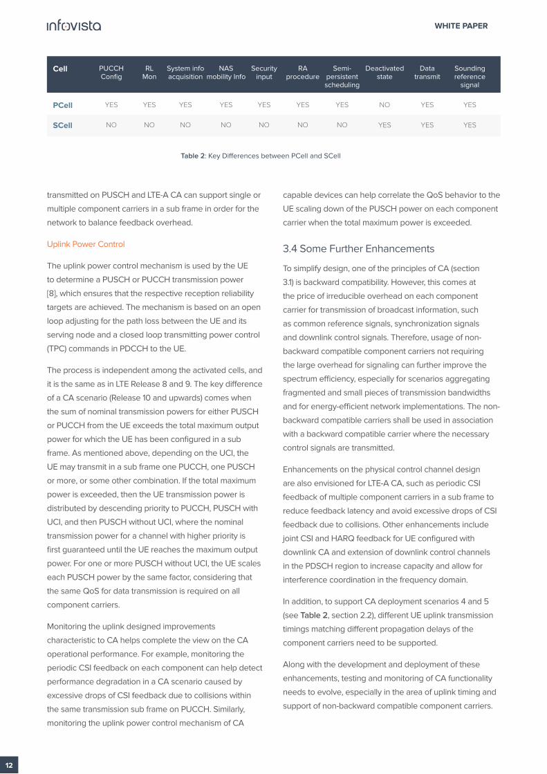
Cell
PUCCH Config
System info acquisition
NAS mobility Info
RL Mon
Security input
RA procedure
Deactivated state
Data transmit
Semi-persistent scheduling
Sounding reference
signal
PCell
SCell
YES
NO
YES
NO
YES
NO
YES
NO
YES
NO
YES
NO
YES
NO
NO
YES
YES
YES
YES
YES
Table 2: Key Differences between PCell and SCell

WHITE PAPER
13
4.0 Carrier Aggregation Testing With TEMS ToolsTEMS™ Investigation is our leading product in CA
performance monitoring in live networks as well as testing
in the lab. The developed features are perfectly suited for
detailed studies of secondary carrier assignments including
performance measurements, site verification, coverage
measurements, neighbor optimization, UE and network
capabilities and settings, and troubleshooting. Therefore,
the TEMS solution for CA covers from the deployment to
the optimization and troubleshooting phase.
This section covers some examples of what can be done
today with TEMS Investigation.
4.1 Carrier Aggregation Deployment Monitoring
As it has been discussed in section 3.2 above, the CA
feature’s performance depends to a large extent on the
SCell deployment.
When deploying a secondary carrier, the performance
in terms of end-user throughput varies with many
parameters including cell configuration, UE capabilities,
radio environment, etc. Therefore, monitoring all these
information elements is critical for successful CA
deployments.
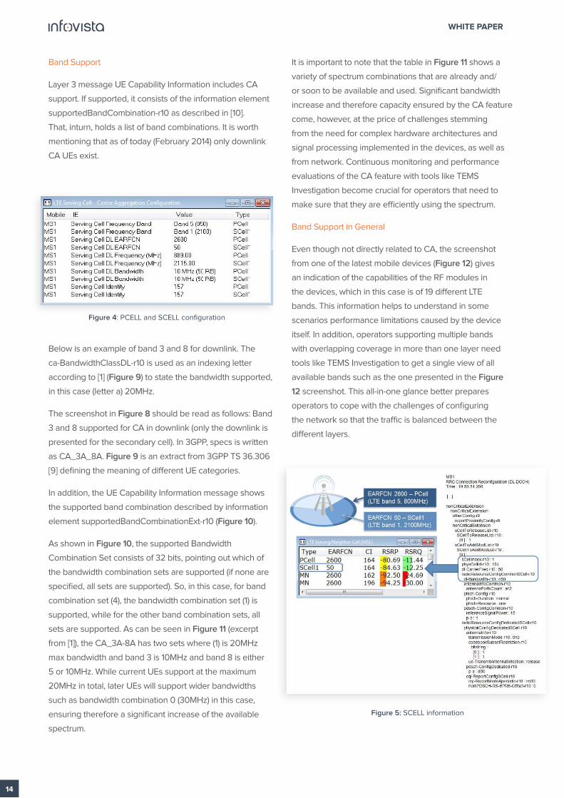
4.1.1 Cell Configuration
TEMS Investigation includes detailed information
about serving cell configuration, both primary and
secondary cell. The information is presented in text format
(Figure 4) and it refers to the band (band number and
frequency band), as well as the frequency of the deployed
cells (both EARFCN and the MHz value). Also, bandwidth
of the cells can easily be found (see Figure 5). There are
a series of parameters related to the secondary carrier
assignment and its configuration.
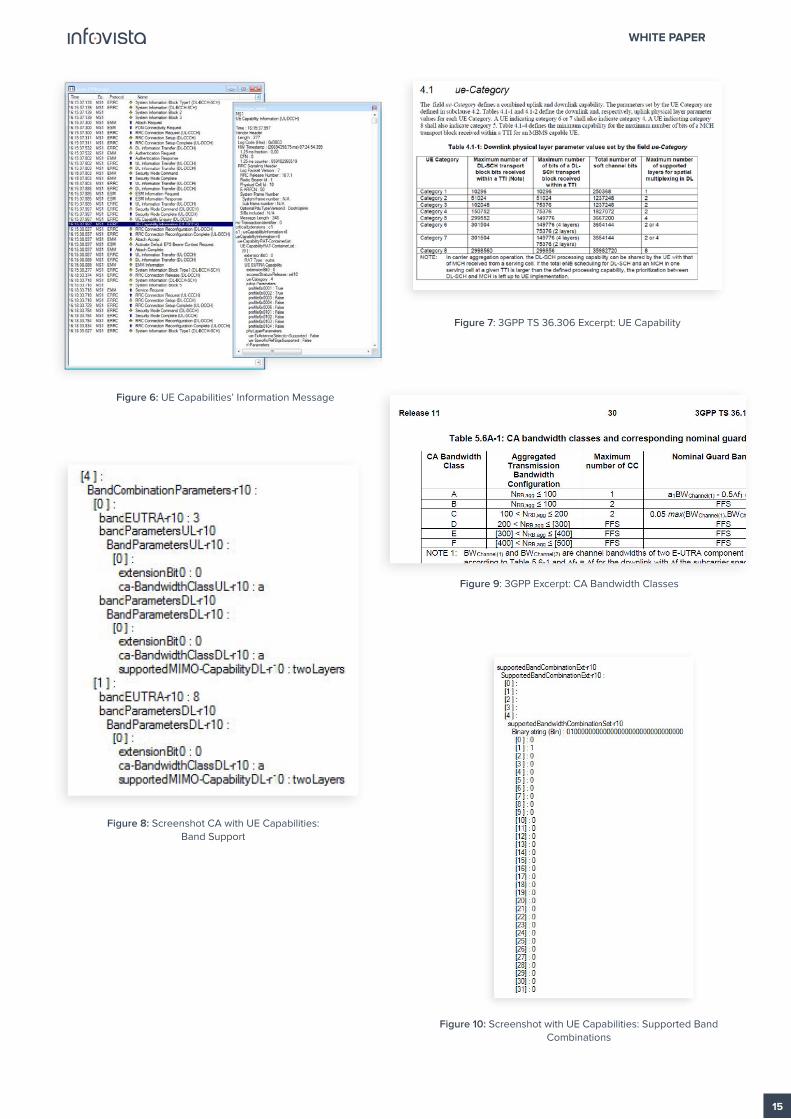
4.1.2 UE Capabilities
As discussed in section 3.2, the UE needs to be able
to support the CA feature. Therefore, capturing the UE
capabilities’ information plays a significant role in CA
deployment monitoring. However, as it can be seen in the
screenshot presented in Figure 6 below, the UE Capability
Information message can consist of a large number of
information lines (almost 1,900 for the presented case).
Therefore, it is crucial to discuss the most meaningful
information that can be used for understanding the UE’s
capabilities for CA support.
UE Category
The field ue-Category in the UE Capability Information
indicates performance figures related to maximum
throughput and number of MIMO layers supported as
described in [9]. It should be noted that a UE category 4
can perfectly support CA. The only limitation is that the
maximum throughput is only 150MB/sec.
Figure 7 is an extract from 3GPP TS 36.306 [9] defining the
meaning of different UE categories.
PARAMETERS’ CATEGORY PARAMETERS
CrossCarrierSchedulingConfig
UplinkPowerControlDedicatedSCell
cif-Presence - pdsch-Start - schedulingCellId
-p0-UE-PUSCH -deltaMCS-Enabled-r10
CQI-ReportConfigSCell-r10 - cqi-ReportPeriodicSCell-r10 - pmi-RI-Report-r10
UplinkPowerControlCommonSCell-r10 - p0-NominalPUSCH-r10 - alpha-r10
PUSCH-ConfigDedicatedSCell-r10 -groupHoppingDisabled-r10 -dmrs-WithOCC-Activated-r10
Table 3: SCell Configuration Parameters
WHITE PAPER
14
Band Support
Layer 3 message UE Capability Information includes CA
support. If supported, it consists of the information element
supportedBandCombination-r10 as described in [10].
That, inturn, holds a list of band combinations. It is worth
mentioning that as of today (February 2014) only downlink
CA UEs exist.
Below is an example of band 3 and 8 for downlink. The
ca-BandwidthClassDL-r10 is used as an indexing letter
according to [1] (Figure 9) to state the bandwidth supported,
in this case (letter a) 20MHz.
The screenshot in Figure 8 should be read as follows: Band
3 and 8 supported for CA in downlink (only the downlink is
presented for the secondary cell). In 3GPP, specs is written
as CA_3A_8A. Figure 9 is an extract from 3GPP TS 36.306
[9] defining the meaning of different UE categories.
In addition, the UE Capability Information message shows
the supported band combination described by information
element supportedBandCombinationExt-r10 (Figure 10).
As shown in Figure 10, the supported Bandwidth
Combination Set consists of 32 bits, pointing out which of
the bandwidth combination sets are supported (if none are
specified, all sets are supported). So, in this case, for band
combination set (4), the bandwidth combination set (1) is
supported, while for the other band combination sets, all
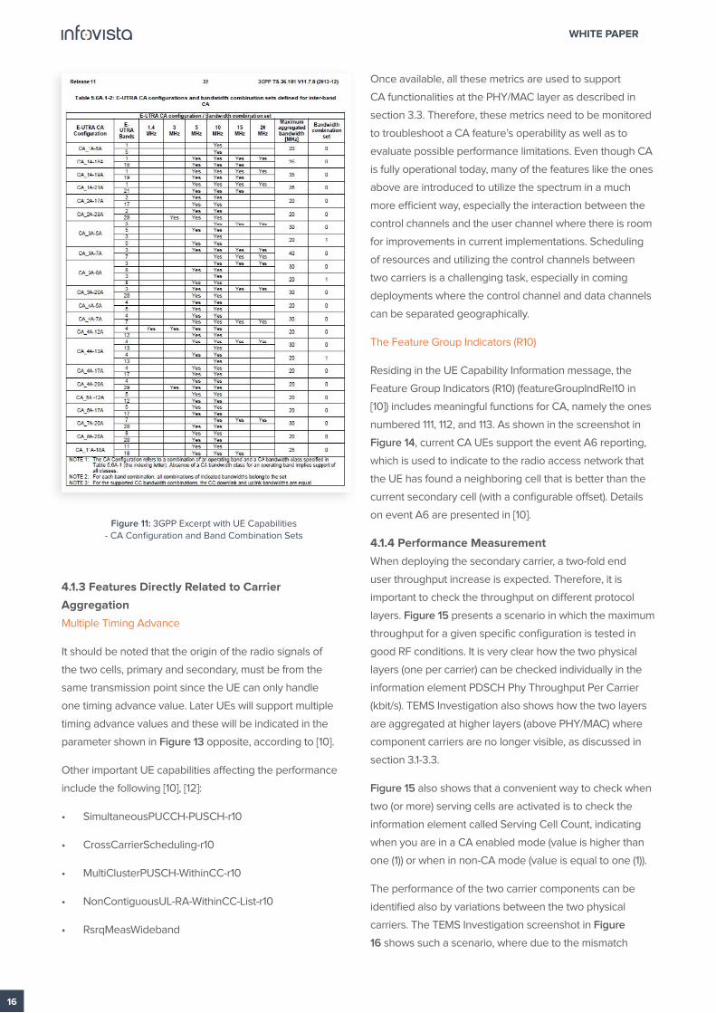
sets are supported. As can be seen in Figure 11 (excerpt
from [1]), the CA_3A-8A has two sets where (1) is 20MHz
max bandwidth and band 3 is 10MHz and band 8 is either
5 or 10MHz. While current UEs support at the maximum
20MHz in total, later UEs will support wider bandwidths
such as bandwidth combination 0 (30MHz) in this case,
ensuring therefore a significant increase of the available
spectrum.
It is important to note that the table in Figure 11 shows a
variety of spectrum combinations that are already and/
or soon to be available and used. Significant bandwidth
increase and therefore capacity ensured by the CA feature
come, however, at the price of challenges stemming
from the need for complex hardware architectures and
signal processing implemented in the devices, as well as
from network. Continuous monitoring and performance
evaluations of the CA feature with tools like TEMS
Investigation become crucial for operators that need to
make sure that they are efficiently using the spectrum.
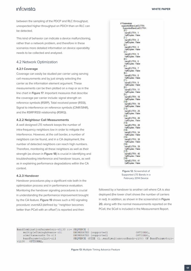
Band Support in General
Even though not directly related to CA, the screenshot
from one of the latest mobile devices (Figure 12) gives
an indication of the capabilities of the RF modules in
the devices, which in this case is of 19 different LTE
bands. This information helps to understand in some
scenarios performance limitations caused by the device
itself. In addition, operators supporting multiple bands
with overlapping coverage in more than one layer need
tools like TEMS Investigation to get a single view of all
available bands such as the one presented in the Figure
12 screenshot. This all-in-one glance better prepares
operators to cope with the challenges of configuring
the network so that the traffic is balanced between the
different layers.
Figure 4: PCELL and SCELL configuration
Figure 5: SCELL information
WHITE PAPER
15
Figure 6: UE Capabilities’ Information Message
Figure 7: 3GPP TS 36.306 Excerpt: UE Capability
Figure 8: Screenshot CA with UE Capabilities: Band Support
Figure 9: 3GPP Excerpt: CA Bandwidth Classes
Figure 10: Screenshot with UE Capabilities: Supported Band Combinations
WHITE PAPER
16
4.1.3 Features Directly Related to Carrier
Aggregation
Multiple Timing Advance
It should be noted that the origin of the radio signals of
the two cells, primary and secondary, must be from the
same transmission point since the UE can only handle
one timing advance value. Later UEs will support multiple
timing advance values and these will be indicated in the
parameter shown in Figure 13 opposite, according to [10].
Other important UE capabilities affecting the performance
include the following [10], [12]:
• SimultaneousPUCCH-PUSCH-r10
• CrossCarrierScheduling-r10
• MultiClusterPUSCH-WithinCC-r10
• NonContiguousUL-RA-WithinCC-List-r10
• RsrqMeasWideband
Once available, all these metrics are used to support
CA functionalities at the PHY/MAC layer as described in
section 3.3. Therefore, these metrics need to be monitored
to troubleshoot a CA feature’s operability as well as to
evaluate possible performance limitations. Even though CA
is fully operational today, many of the features like the ones
above are introduced to utilize the spectrum in a much
more efficient way, especially the interaction between the
control channels and the user channel where there is room
for improvements in current implementations. Scheduling
of resources and utilizing the control channels between
two carriers is a challenging task, especially in coming
deployments where the control channel and data channels
can be separated geographically.
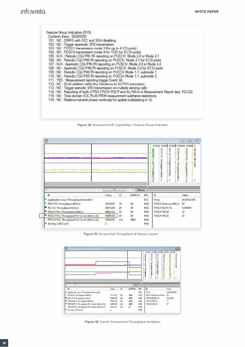
The Feature Group Indicators (R10)
Residing in the UE Capability Information message, the
Feature Group Indicators (R10) (featureGroupIndRel10 in
[10]) includes meaningful functions for CA, namely the ones
numbered 111, 112, and 113. As shown in the screenshot in
Figure 14, current CA UEs support the event A6 reporting,
which is used to indicate to the radio access network that
the UE has found a neighboring cell that is better than the
current secondary cell (with a configurable offset). Details
on event A6 are presented in [10].
4.1.4 Performance Measurement
When deploying the secondary carrier, a two-fold end
user throughput increase is expected. Therefore, it is
important to check the throughput on different protocol
layers. Figure 15 presents a scenario in which the maximum
throughput for a given specific configuration is tested in
good RF conditions. It is very clear how the two physical
layers (one per carrier) can be checked individually in the
information element PDSCH Phy Throughput Per Carrier
(kbit/s). TEMS Investigation also shows how the two layers
are aggregated at higher layers (above PHY/MAC) where
component carriers are no longer visible, as discussed in
section 3.1-3.3.
Figure 15 also shows that a convenient way to check when
two (or more) serving cells are activated is to check the
information element called Serving Cell Count, indicating
when you are in a CA enabled mode (value is higher than
one (1)) or when in non-CA mode (value is equal to one (1)).
The performance of the two carrier components can be
identified also by variations between the two physical
carriers. The TEMS Investigation screenshot in Figure
16 shows such a scenario, where due to the mismatch
Figure 11: 3GPP Excerpt with UE Capabilities - CA Configuration and Band Combination Sets
WHITE PAPER
17
between the sampling of the PDCP and RLC throughput,
unexpected higher throughput on PDCH than on RLC can
be detected.
This kind of behavior can indicate a device malfunctioning,
rather than a network problem, and therefore in these
scenarios more detailed information on device operability
needs to be collected and analyzed.
4.2 Network Optimization
4.2.1 Coverage
Coverage can easily be studied per carrier using serving
cell measurements and by just simply selecting the
carrier as the information element argument. These
measurements can be then plotted on a map or as in the
line chart in Figure 17. Important measures that describe
the coverage per carrier include: signal strength on
reference symbols (RSRP), Total received power (RSSI),
Signal to interference on reference symbols (CINR/SINR),
and the RSRP/RSSI relationship (RSRQ).
4.2.2 Neighbour Call Measurements
A well designed LTE network keeps the number of
intra-frequency neighbors low in order to mitigate the
interference. However, at the cell border, a number of
neighbors can be found, and in a CA deployment, the
number of detected neighbors can reach high numbers.
Therefore, monitoring all these neighbors as well as their
strength (as shown in Figure 18) is crucial in identifying and
troubleshooting interference and handover issues, as well
as in explaining performance degradations within the CA
context.
4.2.3 Handover
Handover procedures play a significant role both in the
optimization process and in performance evaluation.
Monitoring the handover signaling procedures is crucial
in understanding the performance improvement brought
by the CA feature. Figure 19 shows such a HO signaling
procedure: eventA3 (defined by: “neighbor becomes
better than PCell with an offset”) is reported and then
followed by a handover to another cell where CA is also
deployed (the lower chart shows the number of carriers
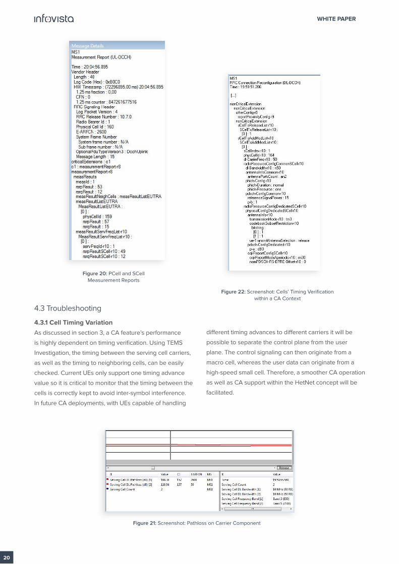
in red). In addition, as shown in the screenshot in Figure
20, along with the normal measurements reported on the
PCell, the SCell is included in the Measurement Report.
Figure 12: Screenshot of
Supported LTE Bands in a
February 2014 Device
Figure 13: Multiple Timing Advance Feature
WHITE PAPER
18
Figure 14: Screenshot UE Capabilities: Feature Group Indicator
Figure 15: Screenshot Throughput at Various Layers
Figure 16: Carrier Component Throughput Variations

WHITE PAPER
19
4.2.4 Pathloss
Using just downlink signal strength measurements on
reference symbols (RSRP) misses one important aspect
when optimizing the radio network: pathloss.
In a typical two-band deployment, the frequency of the
two carriers can differ a lot. Due to the nature of the radio
waves, attenuation is frequency dependent where higher
frequencies attenuate more than lower ones. This means
that traditional signal strength measurements based on
RSRP do not map according to the expected coverage
plans if the eNB output power is the same on both carriers.
A better approach is to use the pathloss, defined as:
• Pathloss = eNB output power - received signal strength
(RSRP)
Using this, a better understanding of the actual cell
configuration and actual coverage of the two carriers can
be achieved. In addition, tuning can be performed to get a
good balance between the two carriers. In the future, UEs
will support CA in the uplink too, and with that, an uplink/
downlink balance per carrier can also be tuned.
The eNB output power is given by layer 3 signaling in RRC
Connection Reconfiguration
(DL-DCCH), individually for the carriers as the:
• pdsch-ConfigCommon / referenceSignalPower: 15
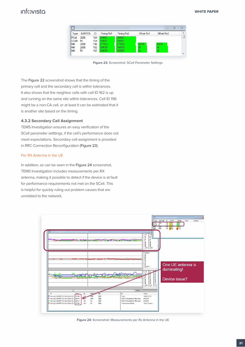
Using pathloss, as shown in the screenshot in Figure 21, a
benefit of a carrier difference of 8 to 10dB can be the result,
using the same output power on both carriers, where one
is on the 850 MHz band and the other on the 2100 MHz
band.
Figure 17: Screenshot: Coverage Performance per Carrier Component
PCell SCell1
Figure 18: Screenshot: Neighbour Call Measurements Figure 19: Screenshot: HO Signallling Procedures within
CA Context
WHITE PAPER
20
4.3 Troubleshooting
4.3.1 Cell Timing Variation
As discussed in section 3, a CA feature’s performance
is highly dependent on timing verification. Using TEMS
Investigation, the timing between the serving cell carriers,
as well as the timing to neighboring cells, can be easily
checked. Current UEs only support one timing advance
value so it is critical to monitor that the timing between the
cells is correctly kept to avoid inter-symbol interference.
In future CA deployments, with UEs capable of handling
different timing advances to different carriers it will be
possible to separate the control plane from the user
plane. The control signaling can then originate from a
macro cell, whereas the user data can originate from a
high-speed small cell. Therefore, a smoother CA operation
as well as CA support within the HetNet concept will be
facilitated.
Figure 20: PCell and SCell Measurement Reports
Figure 21: Screenshot: Pathloss on Carrier Component
Figure 22: Screenshot: Cells’ Timing Verification within a CA Context
WHITE PAPER
21
The Figure 22 screenshot shows that the timing of the
primary cell and the secondary cell is within tolerances.
It also shows that the neighbor cells with cell ID 162 is up
and running on the same site within tolerances. Cell ID 196
might be a non-CA cell, or at least it can be estimated that it
is another site based on the timing.
4.3.2 Secondary Cell Assignment
TEMS Investigation ensures an easy verification of the
SCell parameter setttings, if the cell’s performance does not
meet expectations. Secondary cell assignment is provided
in RRC Connection Reconfiguration (Figure 23).
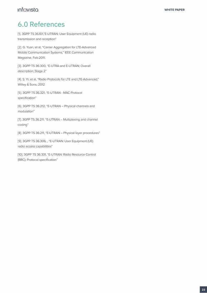
Per RX Antenna in the UE
In addition, as can be seen in the Figure 24 screenshot,
TEMS Investigation includes measurements per RX
antenna, making it possible to detect if the device is at fault
for performance requirements not met on the SCell. This
is helpful for quickly ruling out problem causes that are
unrelated to the network.
Figure 23: Screenshot: SCell Parameter Settings
Figure 24: Screenshot: Measurements per Rx Antenna in the UE
WHITE PAPER
22
5.0 Conclusions
Carrier aggregation with various 3GPP defined bands and
component carrier combinations is the fastest path for
operators to increase data rates as well as improve efficient
spectrum reutilization in various deployment scenarios.
Inheriting the key designs of LTE Release 8 and 9 per
component carrier, LTE-A CA (Release 10 and beyond) has
the advantages of reducing implementation efforts for
faster product availability and system deployment.
However, new capabilities that come from CA operability
do require extensive verification, testing and monitoring of
performance and events referring to:
• Data transmission over two clusters of contiguous
bandwidth in the same carrierSimultaneous
transmission of a control channel and a data channel in
the PCell
• Data transmission from multiple antennas with spatial
multiplexing
• Evaluation of improved CA design of downlink and
uplink control to efficiently support improved data
transmission speeds.
In addition, monitoring CA’s impact on higher layers, such
as cell and mobility management, as well as cell activation/
deactivation events, is needed in order evaluate CA
performance and maximize the benefits of CA functionality.
UE-centric testing solutions, such as TEMS Investigation,
which unveil UE behavior and correlate this with UE
capabilities become key in CA scenario monitoring. In
addition, TEMS Investigation features are perfectly suited
for detailed studies of secondary carrier assignments
including performance measurements, site verification,
coverage measurements, neighbor optimization,
UE and network capabilities and settings, as well as
troubleshooting. The screenshots included in this paper
demonstrate how TEMS Investigation can be easily used
for CA testing and evaluation from the deployment to the
optimization and troubleshooting phase. TEMS solutions for
CA monitoring and performance evaluation will grow along
with future contemplated CA functionality enhancements,
especially in the area of uplink timing and the support of
non-backward-compatible component carriers.
TEMS Investigation features are perfectly suited for detailed studies of secondary carrier assignments including performance measurements, site verification, coverage measurements, neighbor optimization, UE and network capabilities and settings, as well as troubleshooting
WHITE PAPER
23
6.0 References[1]. 3GPP TS 36.101,”E-UTRAN: User Equipment (UE) radio
transmission and reception”
[2]. G. Yuan, et al, “Carrier Aggregation for LTE-Advanced
Mobile Communication Systems,” IEEE Communication
Magazine, Feb.2011.
[3]. 3GPP TS 36.300, “E-UTRA and E-UTRAN; Overall
description; Stage 2”
[4]. S. Yi, et al, “Radio Protocols for LTE and LTE-Advanced,”
Willey & Sons, 2012
[5]. 3GPP TS 36.321, “E-UTRAN - MAC Protocol
specification”
[6]. 3GPP TS 36.212, “E-UTRAN – Physical channels and
modulation”
[7]. 3GPP TS 36.211, “E-UTRAN – Multiplexing and channel
coding”
[8]. 3GPP TS 36.211, “E-UTRAN – Physical layer procedures”
[9]. 3GPP TS 36.306, , “E-UTRAN: User Equipment (UE)
radio access capabilities”
[10]. 3GPP TS 36.331, “E-UTRAN: Radio Resource Control
(RRC); Protocol specification”
Infovista, the leader in modern network performance, provides complete visibility and unprecedented
control to deliver brilliant experiences and maximum value with your network and applications. At the core
of our approach are data and analytics, to give you real-time insights and make critical business decisions.
Infovista offers a comprehensive line of solutions from radio network to enterprise to device throughout
the lifecycle of your network. No other provider has this completeness of vision. Network operators
worldwide depend on Infovista to deliver on the potential of their networks and applications to exceed user
expectations every day. Know your network with Infovista.
About Infovista
© Infovista - All rights reserved.