An Introduction of 3GPP Long Term Evolution (LTE)
40
An Introduction of 3GPP Long Term Evolution (LTE) Speaker : Tsung- Yin Lee
-
Upload
elijah-erickson -
Category
Documents
-
view
25 -
download
0
description
An Introduction of 3GPP Long Term Evolution (LTE). Speaker : Tsung-Yin Lee. Reference. http://www.tcs.com “LTE-Advanced: Future of Mobile Broadband,” TATA Consultancy Services - PowerPoint PPT Presentation
Transcript of An Introduction of 3GPP Long Term Evolution (LTE)
An Introduction of3GPP Long Term Evolution (LTE)
Speaker : Tsung-Yin Lee

2
Reference http://www.tcs.com “LTE-Advanced: Future of Mobile Broadband,”
TATA Consultancy Services Takehiro Nakamura ,“Proposal for Candidate Radio Interface Technol
ogies for IMT‐Advanced Bas d on LTE Release 10 and Beyond,” 3GPP TSG‐RAN Chairman
“3GPP LTE Channels and MAC Layer,” EventHelix.com Inc. 2009 Ahmed Hamza, Network Systems Laboratory Simon Fraser
University, “Long Term Evolution (LTE) - A Tutorial,” October 13, 2009
Jim Zyren, “Overview of the 3GPP Long Term Evolution Physical Layer,” Document Number: 3GPP EVOLUTIONWP Rev0 07/2007
David Astély, Erik Dahlman, Anders Furuskär, Ylva Jading, Magnus Lindström, and Stefan Parkvall, Ericsson Research, “LTE: The Evolution of Mobile Broadband” , IEEE Communications Magazine, April 2009
3
Outline
History of 3GPP LTE Basic Concepts of LTE Introduction of LTE Protocol Compare with LTE and LTE-Advanced Conclusion
4
What is LTE ?
In Nov. 2004, 3GPP began a project to define the long-term evolution (LTE) of Universal Mobile Telecommunications System (UMTS) cellular technology Higher performance Backwards compatible Wide application
5
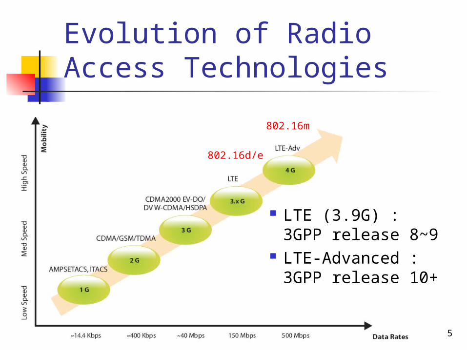
Evolution of Radio Access Technologies
LTE (3.9G) : 3GPP release 8~9
LTE-Advanced :3GPP release 10+
802.16d/e
802.16m
6
LTE Basic Concepts
LTE employs Orthogonal Frequency Division Multiple Access (OFDMA) for downlink data transmission and Single Carrier FDMA (SC-FDMA) for uplink transmission

7
Multipath-Induced Time Delays Result in Inter-Symbol Interference (ISI)
)()()()( tnmtStSty
y(t) : output signalS(t) : input signalS(t-m) : delayed m time input signaln(t) : noise
y(t)
βS(t-m)
S(t)
8
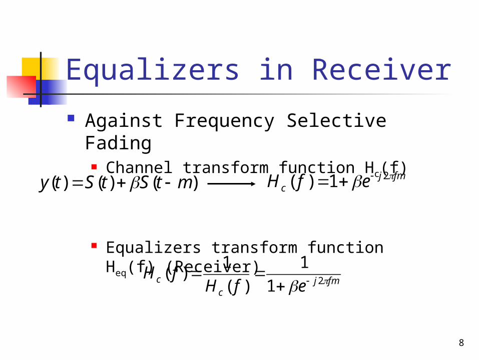
Equalizers in Receiver
Against Frequency Selective Fading Channel transform function Hc(f)
Equalizers transform function Heq(f) (Receiver)
fmjc efH 21)(
fmjc
c efHfH 21
1
)(
1)(
)()()( mtStSty
9
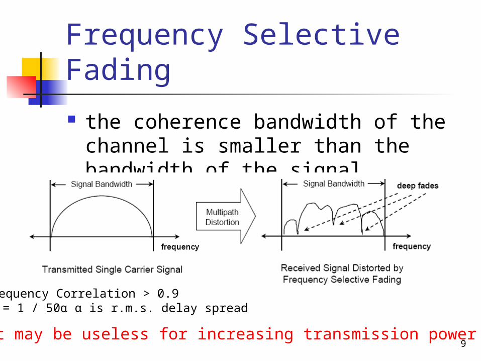
Frequency Selective Fading
the coherence bandwidth of the channel is smaller than the bandwidth of the signal
It may be useless for increasing transmission power
Frequency Correlation > 0.9Bc = 1 / 50α α is r.m.s. delay spread
10
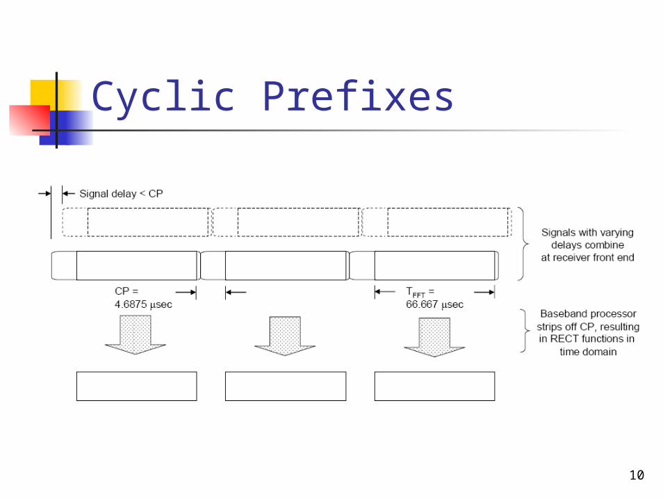
Cyclic Prefixes

11
FDM vs. OFDM
12
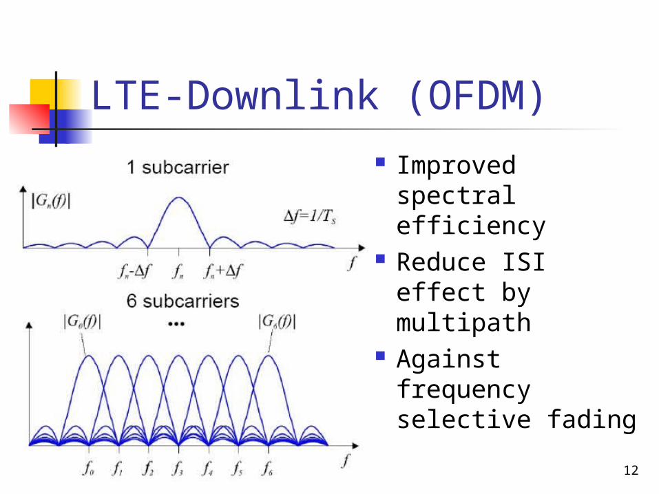
LTE-Downlink (OFDM)
Improved spectral efficiency
Reduce ISI effect by multipath
Against frequency selective fading
13
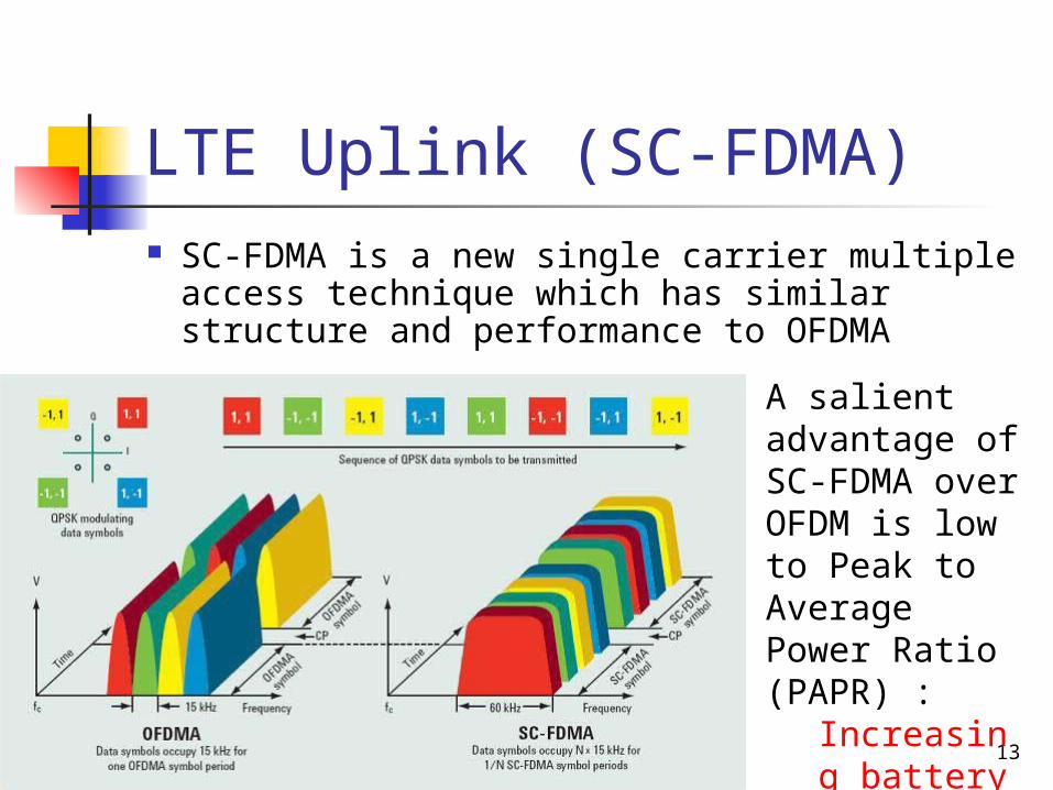
LTE Uplink (SC-FDMA) SC-FDMA is a new single carrier multiple access
technique which has similar structure and performance to OFDMA
A salient advantage of SC-FDMA over OFDM is low to Peak to Average Power Ratio (PAPR) :
Increasing battery life
14
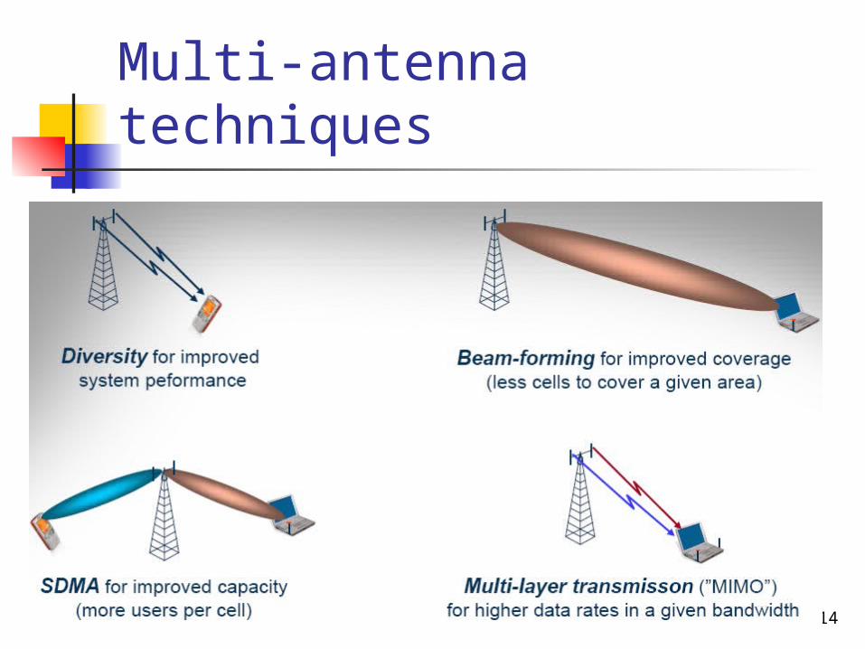
Multi-antenna techniques

15
Generic Frame Structure
Allocation of physical resource blocks (PRBs) is handled by a scheduling function at the 3GPP base station (eNodeB)
Frame 0 and frame 5 (always downlink)
16
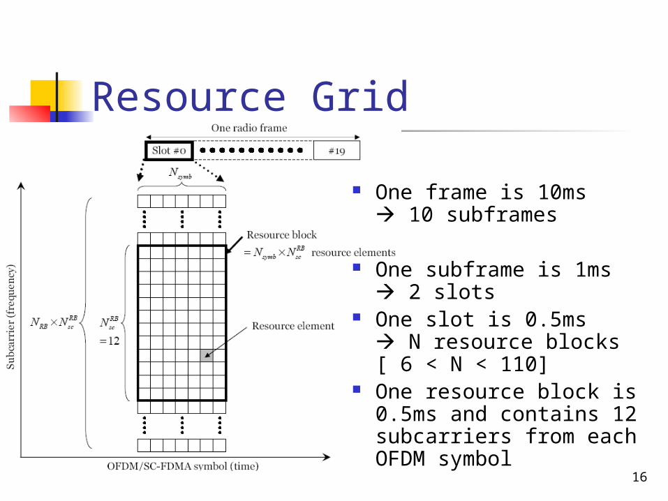
Resource Grid
One frame is 10ms 10 subframes
One subframe is 1ms 2 slots
One slot is 0.5ms N resource blocks[ 6 < N < 110]
One resource block is 0.5ms and contains 12 subcarriers from each OFDM symbol
17
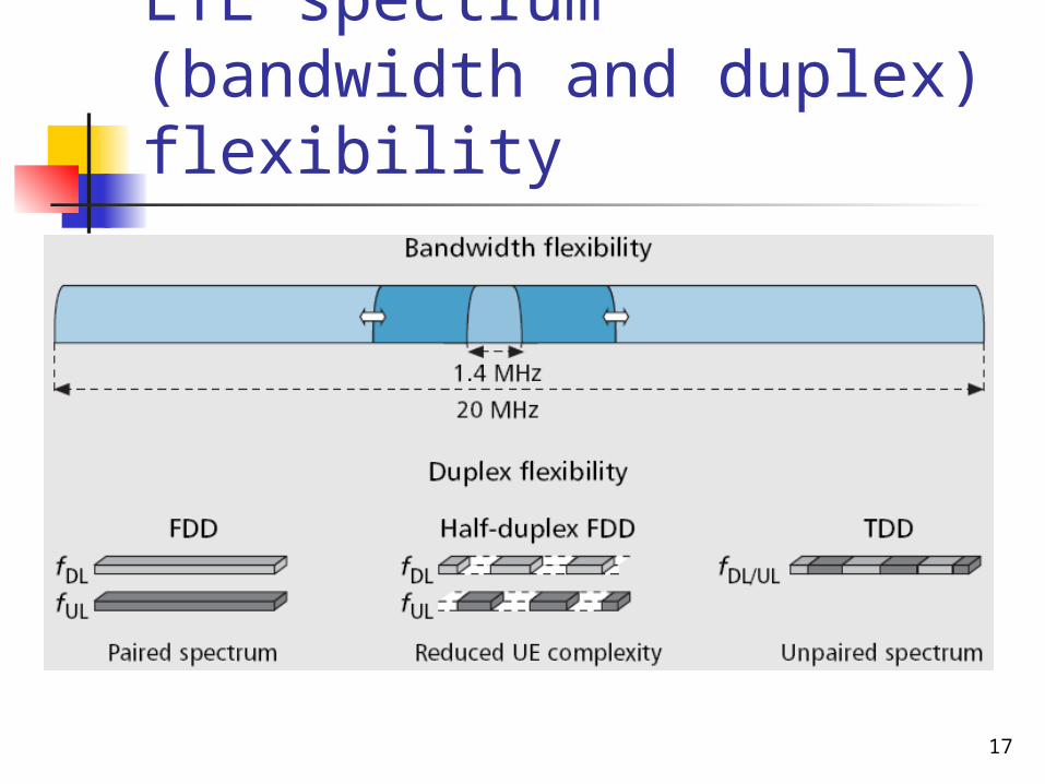
LTE spectrum (bandwidth and duplex) flexibility
18
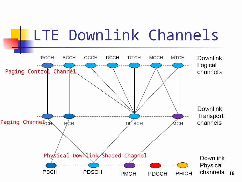
LTE Downlink Channels
Paging Channel
Paging Control Channel
Physical Downlink Shared Channel

19
LTE Uplink Channels
Random Access Channel
Physical Radio Access Channel
Physical Uplink Shared Channel
CQI report

20
LTE Release 8 Key Features (1/2)
High spectral efficiency OFDM in Downlink Single‐Carrier FDMA in Uplink
Very low latency Short setup time & Short transfer delay Short hand over latency and interruption time
Support of variable bandwidth 1.4, 3, 5, 10, 15 and 20 MHz

21
LTE Release 8 Key Features (2/2)
Compatibility and interworking with earlier 3GPP Releases
FDD and TDD within a single radio access technology
Efficient Multicast/Broadcast
22
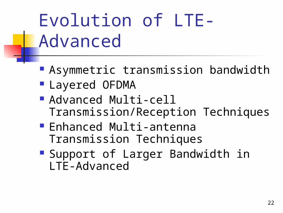
Evolution of LTE-Advanced
Asymmetric transmission bandwidth Layered OFDMA Advanced Multi-cell
Transmission/Reception Techniques Enhanced Multi-antenna Transmission
Techniques Support of Larger Bandwidth in LTE-
Advanced
23
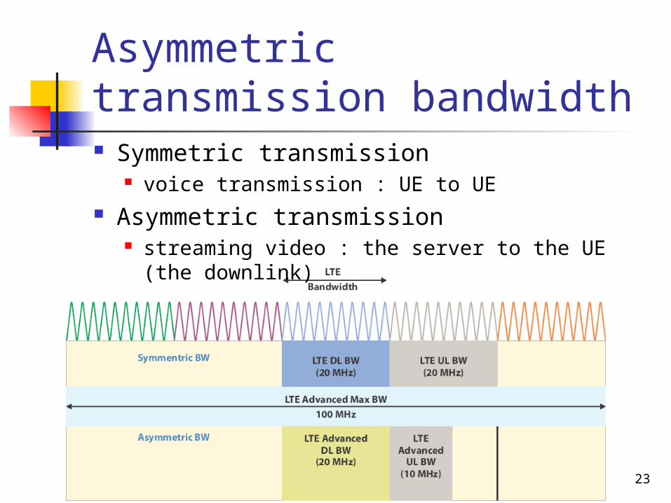
Asymmetric transmission bandwidth Symmetric transmission
voice transmission : UE to UE Asymmetric transmission
streaming video : the server to the UE (the downlink)

24
Layered OFDMA
The bandwidth of basic frequency block is, 15–20 MHz
Layered OFDMA radio access scheme in LTE-A will have layered transmission bandwidth, support of layered environments and control signal formats

25
Advanced Multi-cell Transmission/Reception Techniques
In LTE-A, the advanced multi-cell transmission/reception processes helps in increasing frequency efficiency and cell edge user throughput Estimation unit Calculation unit Determination unit Feedback unit
26
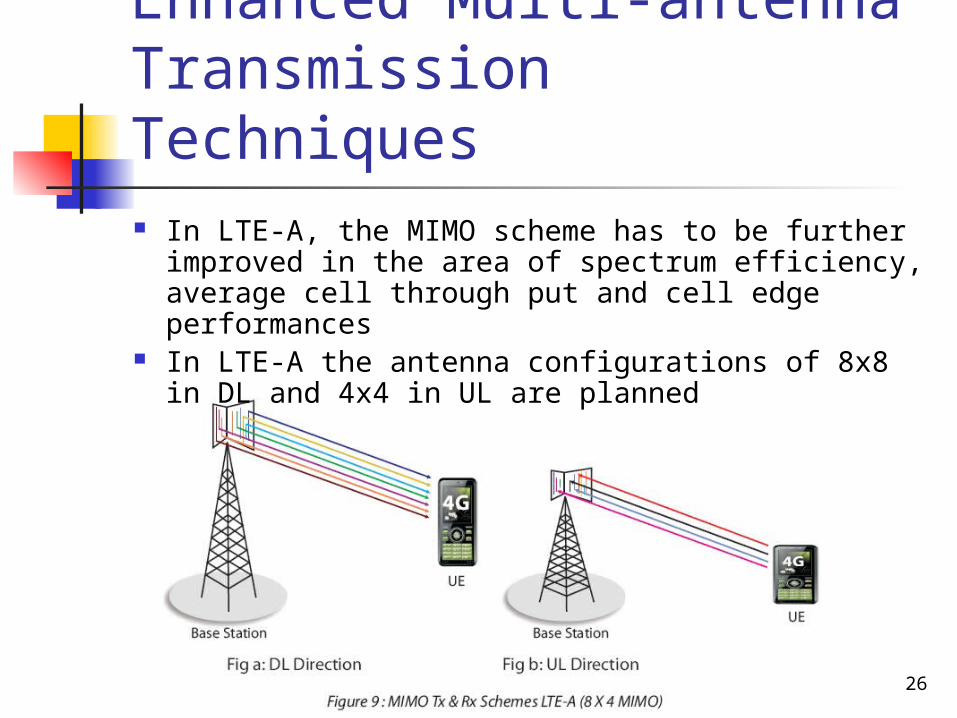
Enhanced Multi-antenna Transmission Techniques In LTE-A, the MIMO scheme has to be further improved
in the area of spectrum efficiency, average cell through put and cell edge performances
In LTE-A the antenna configurations of 8x8 in DL and 4x4 in UL are planned

27
Enhanced Techniques to Extend Coverage Area Remote Radio Requirements (RREs) using optical
fiber should be used in LTE-A as effective technique to extend cell coverage
28
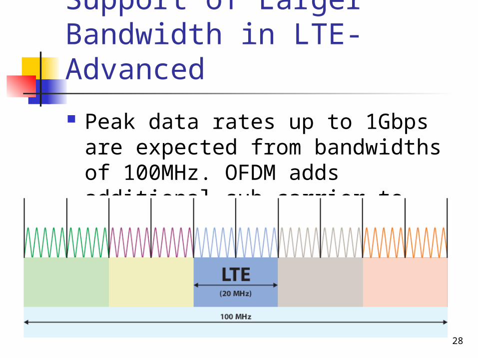
Support of Larger Bandwidth in LTE-Advanced
Peak data rates up to 1Gbps are expected from bandwidths of 100MHz. OFDM adds additional sub-carrier to increase bandwidth

29
LTE vs. LTE-Advanced

30
Conclusion
LTE-A helps in integrating the existing networks, new networks, services and terminals to suit the escalating user demands
LTE-Advanced will be standardized in the 3GPP specification Release 10 (LTE-A) and will be designed to meet the 4G requirements as defined by ITU
31
Backup

32
LTE Downlink Logical Channels
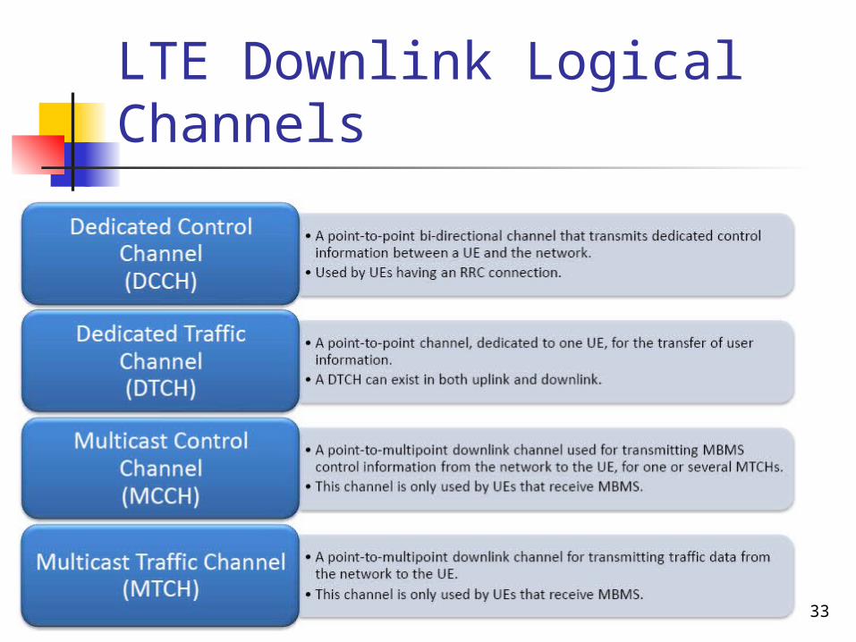
33
LTE Downlink Logical Channels

34
LTE Downlink Transport Channel

35
LTE Downlink Transport Channel
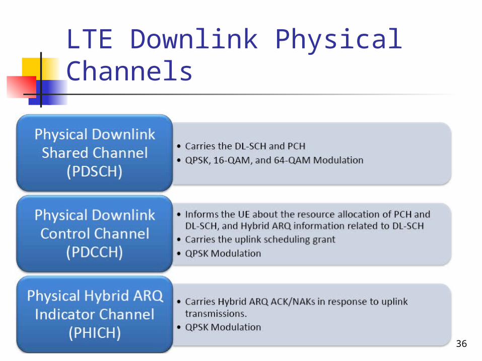
36
LTE Downlink Physical Channels
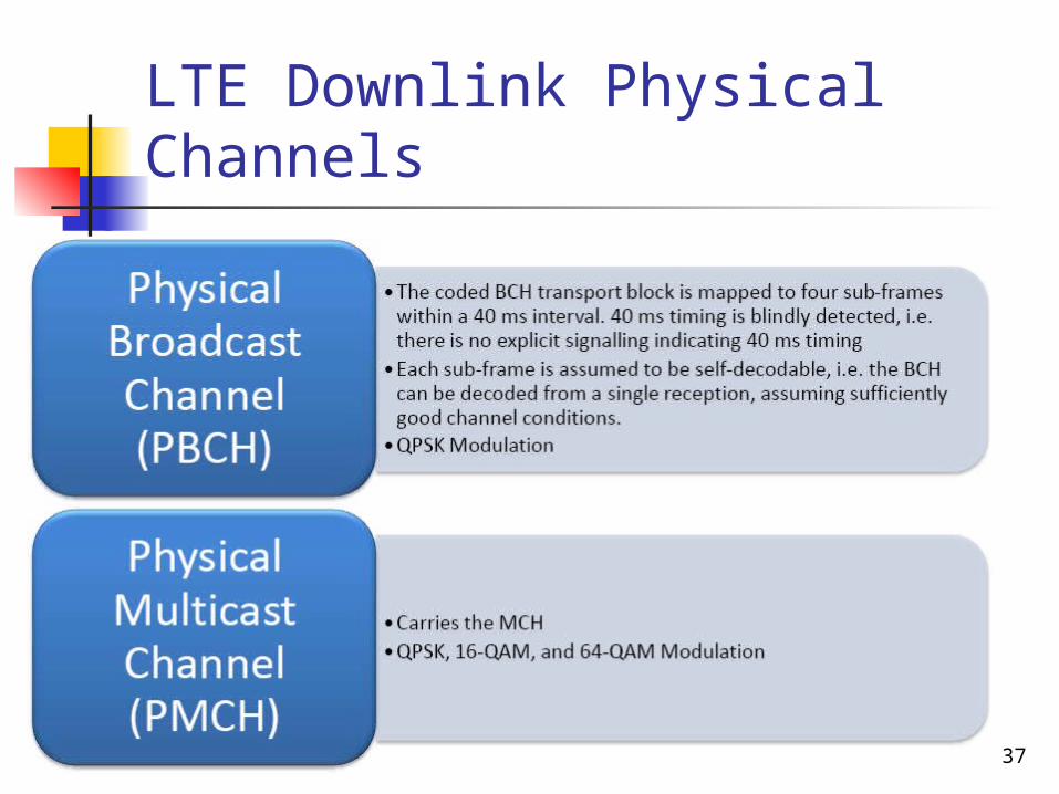
37
LTE Downlink Physical Channels
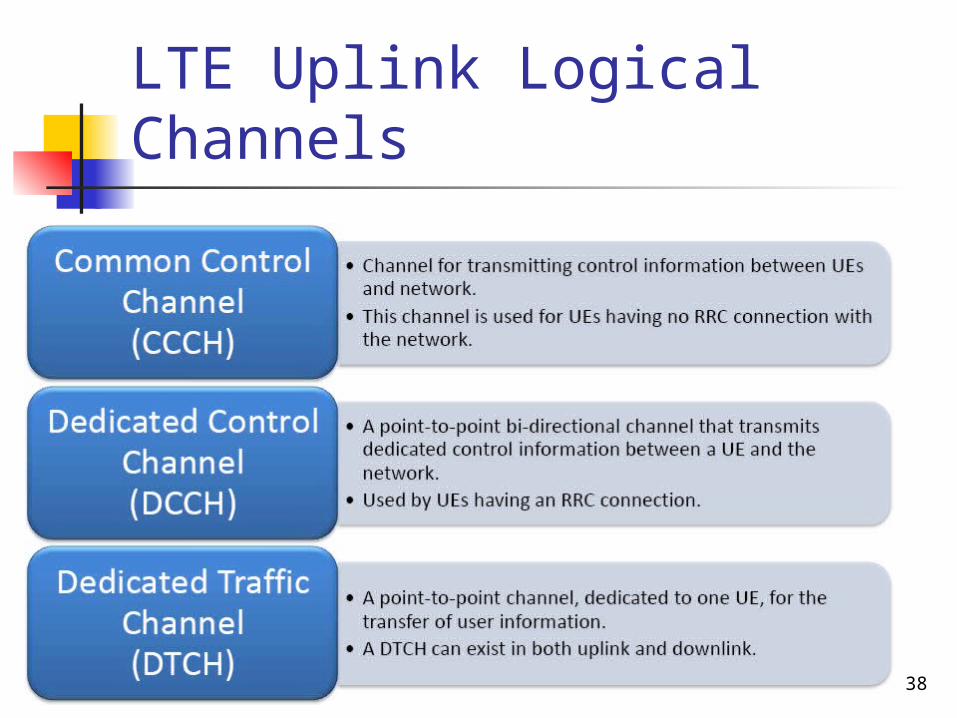
38
LTE Uplink Logical Channels

39
LTE Uplink Transport Channel

40
LTE Uplink Physical Channels