Initial Investigation of Organisational Factors Relevant to Implementing Active Support

An Initial Investigation on the Use of CarbonMicrofibers for Conformal Transmission Lines
B. Braaten #1, A. Iftikhar #2, M. Rafiq #3, A. Naqvi #4, S. Nariyal #5,A. Taylor #6, S. Sajal #7, M. Iskander ∗8, D. Anagnostou ∗9
# Electrical and Computer Engineering Department, North Dakota State University1411 Centennial Blvd., Fargo, ND USA 58104
∗ Electrical and Computer Engineering Department, South Dakota School of Mines and TechnologyRapid City, SD USA 57701
1 [email protected], [email protected] [email protected]
3 [email protected] [email protected]
5 [email protected] [email protected] [email protected]
8 [email protected] [email protected]
Abstract—The use of carbon microfiber tow (or bundle) forconformal transmission lines (TLs) is initially investigated inthis work. Two different microfiber TLs have been synthesizedand tested. A 28.2 mm long microfiber TL was manufacturedto demonstrate the wave propagating properties. Once thesecharacteristics were determined, a microstrip TL was preparedby attaching 1oz conducting copper tape to a conformal surfaceand a similar microfiber TL with the same length and on thesame substrate was manufactured. This prototype was then usedto compare the propagation characteristics of the microfiber TLto the traditional and well established microstrip TL. Overall,it has been shown that the microfiber TL can support wavepropagation in a manner similar to a microstrip TL; however, theattenuation constant appears to be rather large for frequenciesabove 500 MHz.
I. INTRODUCTION
Conformal antennas can be used in wireless systems ina manner different than antennas on printed circuit boards(PCB). Because conformal antennas can be attached to singlyor doubly curved surfaces [1]-[7], wearable clothing [8]-[20] or structures with vibrating surfaces [21]-[27] they haveparticular applications to vehicles, aircraft, sensors and searchand rescue personnel. There are many challenges with thelong term use of conformal antennas such as element failure,conductor breakage and substrate durability. To address theseissues, many different research areas have been developed in-cluding antenna pattern distortion and correction due to varioussurface deformations [3], [8], [27], new flexible substrates [4]and unique manufacturing techniques [20].
Load bearing antennas have recently received attention [20]as a promising way to integrate microwave antennas intoan existing structure without compromising the behaviour.One method to reinforce an overall structure is to selectivelyintroduce carbon microfibers [28] to create a lightweight
Fig. 1. Picture of the microfiber bundle being considered in this work.
composite material that not only provide tensile strength,provide electrical properties as well. In this paper, the appli-cation of carbon microfibers to conformal (flexible) microstriptransmission lines (TLs) is initially investigated. A picture ofthe carbon microfiber tow (or bundle) considered in this workis shown in Fig. 1. Initially, the microfiber bundles are attachedto a flat grounded substrate to create a microfiber TL. Thenthe propagation characteristics of this TL are investigated. Themicrofiber TL is next attached to a non-conducting sphere toinvestigate the TL properties on a conformal substrate. Finally,a traditional microstrip TL is manufactured and tested ona flexible substrate and compared to a microfiber TL withsimilar dimensions on the same substrate. By investigatingthe electrical properties of microfiber bundles, new methodsfor integrating embedded conducting TLs, antennas and RFelectronics within composite materials may be explored.
II. THE PROTOTYPE CARBON MICROFIBER BUNDLETRANSMISSION LINE
The flexible bundle of microfibers in Fig. 1 was man-ufactured by Fibre Glast Development Corp. [28] and thefiber properties are summarized in Table I. To initially study
978-1-4673-5208-6/13/$31.00 ©2013 IEEE
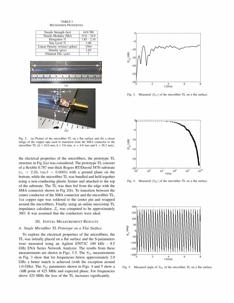
TABLE IMICROFIBER PROPERTIES.
Tensile Strength (ksi) 610-700Tensile Modulus (Msi) 33.6 - 34.9
Elongation % 1.85 - 2.10Size Level % 1.00
Linear Density (w/size) (g/km) 1564Density (g/cc) 1.82
Filament Dia. (µm) 7
(a)
(b)
L
w
h
d
Fig. 2. (a) Picture of the microfiber TL on a flat surface and (b) a closerimage of the copper tape used to transition from the SMA connector to themicrofiber TL (d = 10.0 mm, h = 5.0 mm, w = 4.0 mm and L = 28.2 mm).
the electrical properties of the microfibers, the prototype TLstructure in Fig 2(a) was considered. The prototype TL consistsof a flexible 0.787 mm thick Rogers RT/Duroid 5870 substrate(εr = 2.33, tan δ = 0.0005) with a ground plane on thebottom, while the microfiber TL was bundled and held togetherusing a non-conducting plastic fixture and attached to the topof the substrate. The TL was then fed from the edge with theSMA connector shown in Fig 2(b). To transition between thecenter conductor of the SMA connector and the microfiber TL,1oz copper tape was soldered to the center pin and wrappedaround the microfibers. Finally, using an online microstrip TLimpedance calculator, Zo was computed to be approximately30Ω. It was assumed that the conductors were ideal.
III. INITIAL MEASUREMENT RESULTS
A. Single Microfiber TL Prototype on a Flat Surface
To explore the electrical properties of the microfibers, theTL was initially placed on a flat surface and the S-parameterswere measured using an Agilent E5071C 100 kHz - 8.5GHz ENA Series Network Analyzer. The results from thesemeasurements are shown in Figs. 3-5. The S11 measurementsin Fig. 3 show that for frequencies below approximately 2.0GHz a better match is achieved (with the exception around1.0 GHz). The S21 parameters shown in Figs. 4 and 5 show a-3dB point of 425 MHz and expected phase. For frequenciesabove 425 MHz the loss of the TL increases significantly.
0 2 4 6 8−30
−25
−20
−15
−10
−5
0
f (GHz)
|S11
| (dB
)
Fig. 3. Measured |S11| of the microfiber TL on a flat surface.
105
106
107
108
109
1010
−25
−20
−15
−10
−5
0
f (Hz)
|S21
| (dB
)
Fig. 4. Measured |S21| of the microfiber TL on a flat surface.
0 2 4 6 8−200
−150
−100
−50
0
50
100
150
200
f (GHz)
φ 21 (
deg)
Fig. 5. Measured angle of S21 of the microfiber TL on a flat surface.

Fig. 6. Picture of the microfiber TL on a non-conducting styrofoam sphere.
0 2 4 6 8−30
−25
−20
−15
−10
−5
0
f (GHz)
|S11
| (dB
)
Fig. 7. Measured |S11| of the microfiber TL on a spherical surface.
B. Single Microfiber TL Prototype on a Curved Surface
Next, the prototype fiber TL in Fig. 2(a) was placed on anon-conducting sphere with a radius of 20.32 cm, as shown inFig. 6. The S-parameters from these measurements are shownin Figs. 7 - 9. In a similar manner to the flat TL, the curved TLalso has a fair match with the exception of frequencies below600 MHz. On the other hand, the -3dB point was reduced to100 MHz.
Overall, the spherical surface appears to affect the -3dBpoint and the lower matching frequencies of the fiber TL.This change is thought to be due to the radiation from theTL and the deformation of the microfiber conductors. As theTL conforms to the sphere, the width of bundle increases andthe threads move closer (i.e., the threads are more compact).
C. Microstrip and Microfiber TL Prototype Comparison on aFlat Surface
For comparison purposes, a microstrip and microfiber TLwas manufactured on the same 20 mil Rogers 5870 substrate asthe microfiber TL in the previous subsections. The conductorfor the microstrip TL was made using 1oz copper tape, asshown in Fig. 10. Using the Agilent network analyzer, theS-parameters were measured for each TL on a flat surface.The results from these measurements are shown in Figs. 12- 14. Again, using an on line microstrip-line calculator, forthe dimensions in Fig. 10 the characteristic impedance of thecopper tape microstrip TL was determined to be 42Ω.
105
106
107
108
109
1010
−35
−30
−25
−20
−15
−10
−5
0
f (Hz)
|S21
| (dB
)
Fig. 8. Measured |S21| of the microfiber TL on a spherical surface.
0 2 4 6 8−200
−150
−100
−50
0
50
100
150
200
f (GHz)
φ 21 (
deg)
Fig. 9. Measured angle of S21 of the microfiber TL on a spherical surface.
D. Microstrip and Microfiber TL Prototype Comparison on aCurved Surface
Next, the prototype board with the microstrip and fiber TLwas attached to a non-conducting surface with a radius ofcurvature of 10 cm and the S-parameters were measured. Apicture of the prototype being measured is shown in Fig. 11and the results are also shown in Figs. 12 - 14.
Overall, the fiber TL response was similar to the TL in Fig.2(a). When compared to the microstrip TL with the coppertape, the matching is similar; however, the -3dB in the S21
plot is approximately 250 MHz for both cases.
IV. DISCUSSION
The TL in Fig. 2(a) was chosen to be long enough todemonstrate wave propagation only. The measurements areused to simply illustrate that matching can be achieved, signalpropagation from one port to the other can be observed and thephase constant is similar to the phase constant of a microstripTL.
Since wave propagation was observed, the prototype boardin Fig. 10 was then manufactured to compare the propagationcharacteristics of the fiber TL to the microstrip TL. It hasbeen shown that matching can be achieved, and for frequencies

M
Fig. 10. Picture of the microstrip and microfiber TL on a conformal substrate(M = 92.0 mm).
Np
q
Fig. 11. Picture of the microstrip and microfiber TL being measured on acurved surface (N = 38.0 mm, p = 2.9 mm, q ≈ 5.0 mm).
below approximately 500MHz, the attenuation constant of thefiber TL may be low enough for some applications.
Finally, it should be mentioned that several microfiber TLswere manufactured with varying lengths and more denselypacked carbon microfibers. The matching did not appear tobe affected much by more fibers; however, the attenuationconstant of the TL was reduced.
V. CONCLUSION
In this paper, two prototype microfiber transmission lineswere manufactured and tested on various surfaces. First, amicrofiber TL 28.2 mm long was synthesized and used todemonstrate wave propagation. Then, a microstrip TL withcopper tape and a microfiber TL with the same length of themicrostrip TL was manufactured and the S-parameters werecompared on a flat and conformal surface. This comparisonillustrated the difference between the microfiber TL and theconventional microstrip TL. Overall, it was determined thatthe matching characteristics of the microfiber TL are similarto the microstrip TL; however, the attenuation constant of themicrofiber TL was much larger for frequencies above approx500 MHz.
REFERENCES
[1] R. L. Haupt, Antenna Arrays: A Computational Approach, John Wileyand Sons, Ltd., Hoboken, New Jersey, 2010.
0 1 2 3 4−60
−50
−40
−30
−20
−10
0
f (GHz)
|S11
| (dB
)
Microstrip TL − FlatFiber TL − FlatMicrostrip TL − CurvedFiber TL − Curved
Fig. 12. Measured |S11| of the microstrip and fiber TL on a flat and curvedsurface.
0 1 2 3 4−30
−25
−20
−15
−10
−5
0
f (GHz)
|S21
| (dB
)
Microstrip TL − FlatFiber TL − FlatMicrostrip TL − CurvedFiber TL − Curved
Fig. 13. Measured |S21| of the microstrip and fiber TL on a flat and curvedsurface.
0 1 2 3 4−200
−150
−100
−50
0
50
100
150
200
250
300
f (GHz)
φ 21 (
deg)
Microstrip TL − FlatFiber TL − FlatMicrostrip TL − CurvedFiber TL − Curved
Fig. 14. Measured angle of S21 of the microstrip and fiber TL on a flat andcurved surface.

[2] R. C. Hansen, Phased Array Antennas, John Wiley and Sons, Inc., NewYork, NY, 1998.
[3] P. L. O’Donovan and A.W. Rudge, “Adaptive control of a flexible lineararray,” Electron. Lett., vol.9, no.6, pp.121-122, Mar. 22, 1973.
[4] D. J. Chung, S. K. Bhattacharya, G. E. Ponchak and J. Papapolymerou,“An 8x8 lightweight flexible multilayer antenna array,” Proc. IEEEAntennas Propag. Soc. Int. Symp. Dig., June 1-5, 2009, Charleston, SC.
[5] M. A. Aziz, S. Roy, L. A. Berge, I. Ullah and B. D. Braaten, ”Aconformal CPW folded slot antenna array printed on a Kapton substrate,”Accepted for publication in the 2012 European Conf. on AntennasPropag. (EuCAP), Prague, Czech. Republic, Mar. 2012.
[6] K. Wincza and S. Gruszczynski, “Influence of Curvature Radius onRadiation Patterns in Multibeam Conformal Antennas,” 36th EuropeanMicrow. Conf., pp. 1410-1413, Sept. 10 - 15, 2006.
[7] C. A. Balanis, Antenna Theory: Analysis and Design, 3rd Ed., JohnWiley and Sons, Ltd., Hoboken, New Jersey, 2005.
[8] P. Salonen, Y. Rahmat-Samii, H. Hurme and M. Kivikoski, “Dual-bandwearable textile antennas,” Proc. IEEE Antennas Propag. Soc. Int. Symp.Dig., pp. 463-466, vol. 1, Jun. 20-25, 2004.
[9] S. Zhu and R. Langley, “Dual-Band Wearable Textile Antenna on anEBG Substrate,” IEEE Trans. on Antennas Propag., pp. 926 - 935, vol.57 no. 4, Apr. 2009.
[10] P. Salonen, Y. Rahmat-Samii, M. Schaffrath, and M. Kivikoski, “Effectof textile materials on wearable antenna performance: A case study ofGPS antennas,” in Proc. IEEE Antennas Propag. Soc. Int. Symp., 2004,vol. 1, pp. 459-462.
[11] T. F. Kennedy, P.W. Fink, P.W., A.W. Chu, N.J. Champagne, G.Y. Linand M.A. Khayat, M.A., “Body-Worn E-Textile Antennas: The Good,the Low-Mass, and the Conformal,” IEEE Trans. on Antennas Propag.,pp. 910 - 918, vol. 57, no. 4, Apr. 2009
[12] F. Declercq, H. Rogier and C. Hertleer, “Permittivity and Loss TangentCharacterization for Garment Antennas Based on a New Matrix-PencilTwo-Line Method,” IEEE Trans. on Antennas Propag., pp. 2548 - 2554,vol. 56, no. 8, Aug. 2008.
[13] M. Klemm and G. Troester, “Textile UWB antennas for wireless bodyarea networks,” IEEE Trans. Antennas Propag., vol. 54, pp. 3192-3197,2006.
[14] P. Salonen, Y. Rahmat-Samii, and M. Kivikoski, “Wearable antennas inthe vicinity of human body,” in Proc. IEEE Antennas Propag. Soc. Int.Symp., 2004, vol. 1, pp. 467-470.
[15] C. Cibin, P. Leuchtmann, M. Gimersky, R. Vahldieck, and S. Mosci-broda, “A flexible wearable antenna,“ in Proc. IEEE Antennas Propag.Soc. Int. Symp., 2004, vol. 4, pp. 3589-3592.
[16] Y. Byram, Y. Zhou, B. S. Shim, S. Xu, J. Zhu, N. A. Kotov and J. L.Volakis, “E-textile conductors and polymer composites for conformallightweight antennas,” IEEE Trans. on Antennas Propag., pp. 2732 -2736, vol. 56, no. 8, Aug. 2010.
[17] D. Psychoudakis, G. Y. Lee, C. - C. Chen and J. L. Volakis, “Estimatingdiversity for body-worn antennas,” 3rd European Conference on Anten-nas and Propagation (EuCAP), March 23-27, 2009, Berlin Germany.
[18] J. - S. Roh, Y. - S. Chi, J. - H. Lee, Y. Tak, S. Nam and T. J.Kang, “Embroidered wearable multiresonant folded dipole antenna forRF reception,” IEEE Antennas Wireless Propag. Lett., pp. 803 - 806,vol. 9, 2010.
[19] S. E. Morris, Y. Bayram, L. Zhang, Z. Wang, M. Shtein and J. L.Volakis, “High-strength, metalized fibers for conformal load bearingantenna applicaitions,” IEEE Trans. on Antennas Propag., pp. 3458 -3462, vol. 59, no. 9, Sep. 2011.
[20] Z. Wang, L. Zhang, Y. Bayram and J. L. Volakis, “Multilayer printing ofembroidered RF circuits on polymer composites,” Proc. IEEE AntennasPropag. Soc. Int. Symp. Dig., July 3 - 8, 2011, Spokane WA.
[21] H. Schippers, G. Spalluto and G. Vos, “Radiation analysis of conformalphased array antennas on distorted structures,” 12th International Con-ference on Antennas and Propagation (ICAP 2003), Mar. 31 - Apr. 3,2003, pp. 160-163.
[22] H. Schippers, J. Verpoorte, P. Jorna, A. Hulzinga, A. Meijerink, C.Roeloffzen, R. G. Heideman, A. Leinse and M. Wintels, “Conformalphased array with beam forming on airborne satellite communication,”International ITG Workshop on Smart Antennas, 26-27 Feb. 2008, pp.343-350.
[23] H. Schippers, P. Knott, T. Deloues, P. Lacomme and M. R.Scherbarth, “Vibrating antennas and compensation techniques researchin NATO/RTO/SET 087/ RTG 50,” IEEE Aerospace Conference, Mar.3 - 10, 2007, pp. 1-13.
[24] P. Jorna, H. Schippers and J. Verpoorte, “Beam synthesis for conformalarray antennas with efficient tapering,” Proc. of 5th Europ. Workshopon Conformal Antennas, Bristol, Sept. 11-12, 2007.
[25] P. Knott, “Deformation and vibration of conformal antenna arrays andcompensation techniques,” Meeting proc. RTO-MP-AVT-141, paper 19,pp. 1-12, 2006.
[26] T. J. Seidel, W. S. T. Rowe and K. Ghorbani, “Passive compensationof beam shift in a bending array,” Prog. in Electrom. Research, vol. 29,pp. 41-53, 2012.
[27] B. D. Braaten, M. A. Aziz, S.Roy, S. Nariyal, I. Irfanullah, N. F.Chamberlain, M. T. Reich and D. E. Anagnostou, “A Self-AdaptingFlexible (SELFLEX) Antenna Array for Changing Conformal SurfaceApplications,” IEEE Trans. on Antennas and Propag., pp. 655 - 665,vol. 61, no. 2, Feb. 2013.
[28] Fibre Glast Development Corp., [online] (Feb. 2013)www.fibreglast.com, last access date: 2013.
[29] Ansys Inc., Ansoft HFSS, Version 13.0.1, [online] (Jan. 2013)www.ansoft.com, last access date: 2013.
[30] Rogers Corporation, (2013) [online] www.rogerscorp.com.