NR Overview · PDF file10 GHz. 30 GHz. 100 GHz. 1 GHz. 3 GHz. 10 GHz. 30 GHz. 100 GHz

1
Abstract— It is a well known fact that the traditional 1-18 GHz
Double Ridge Guide Horn (DRGH) antenna suffers from pattern deterioration above 12 GHz. At these frequencies, instead of maintaining a single main lobe radiation pattern, the pattern splits up into four lobes. It was shown in the literature that higher order modes are causing the pattern breakup. A benchmark study is performed to establish the performance of typical current and historic 1-18 GHz DRGH antennas. The performance of the antennas are evaluated in terms of gain, VSWR and radiation patterns. An improved 1-18 GHz DRGH antenna is presented. The new design has better gain and VSWR performance without any pattern deterioration. It also consists of significantly fewer parts, reducing the possibility of performance deterioration due to gaps between parts. Two prototypes of the new design were manufactured and tested with excellent agreement between measured and simulated results. The aperture dimensions of the new design are identical to that of the traditional DRGH, making it the only 1-18 GHz DRGH without pattern breakup whose aperture dimensions comply with the requirements specified in MIL-STD-461F - 24.2 by 13.6 cm.
Index Terms— Broadband ridged horn antenna, EMC (ElectroMagnetic Compatibility) measurements.
I. INTRODUCTION
The traditional 1-18 GHz DRGH antenna was adapted from designs by Kerr for a 1-12 GHz horn [1]. The 1-18 GHz antenna is used extensively in antenna and ElectroMagnetic Compatibility (EMC) measurements and in feeds for reflector systems. In these applications, a well behaved antenna pattern is an absolute necessity. Standards such as MIL-STD-461F, ANSI-C 63.2-1987 and CISPR 16-1-4 specifies wideband 1-18 GHz DRGH antennas suitable for radiated emissions and susceptibility testing [2]-[4].
It is well known that the pattern of this antenna deteriorates in the upper frequency band above 12 GHz, [5]-[7]. The main beam splits into four large side lobes and the boresight gain reduces by approximately 6 dB. This makes the use of these antennas for EMC and measurement applications less desirable. A number of tolerance and sensitivity studies using
Manuscript received 6 June, 2011. This work was supported in part by the
National Research Foundation (NRF) of South-Africa. B. Jacobs is with the University of Pretoria, Pretoria 0002, South-Africa
and also with Saab Electronic Defense Systems, EW Operations, Antennas Group, Centurion, South-Africa (e-mail: [email protected]).
J. W. Odendaal and J. Joubert are with the Centre for Electromagnetism, University of Pretoria, Pretoria 0002, South Africa.
commercial numerical solvers viz. FEKO, CST and HFSS followed to investigate the causes of the pattern deterioration [8]-[11]. Subsequently, a new open boundary type of horn design that produces a single main beam across the band was developed [10]-[12]. The new design included a number of changes:
• The dielectric sidewalls were removed to improve the radiation characteristics of the DRGH antenna above 12 GHz. It was found in [10] that the dielectric rather than the metallic strips of the sidewalls causes an on-axis gain drop at 18 GHz. The removal of the sidewalls was at the expense of the low frequency (1-4 GHz) performance – the beamwidths increased and the gain decreased.
• The ridges and the conducting flares (top and bottom) were redesigned to reduce edge diffraction and improve the aperture match. The ridge’s curvature was modified to a linear section near the feed point, an intermediate exponential section and a circular section near the aperture [11]. The flare outlines were changed to eliminate sharp corners due to the removal of the sidewalls.
• The coax to ridge waveguide transition was redesigned and mode suppression fins were included to prevent the excitation of higher order modes. A cavity was included (just behind the mode suppression fins) to reduce the VSWR [12].
• The antenna was finally scaled down to further improve the high frequency behaviour.
These changes significantly improved the antenna performance at the higher frequencies, but by discarding the dielectric sidewalls and scaling the antenna to improve the high frequency behaviour of the antenna, the performance in the low frequency band deteriorated. The alternative open boundary horn design therefore suffers from an increase in VSWR and a decrease in gain between 1 and 3 GHz.
In addition to the pattern and gain performance issues, the traditional DRGH antenna also suffers from performance deterioration when incorrect assembly or manufacturing tolerances causes gaps between individual parts. Recently in [13] it was shown that gaps in the order of 0.5-0.05 mm between various subsections in the waveguide launcher assembly leads to severe resonance effects in boresight gain and VSWR, and it was found that the coaxial feeding section is especially sensitive.
In this paper we proposed an improved double ridge guide horn antenna with metallic grid sidewalls to restore the lower
An Improved Design for a 1-18 GHz Double- Ridged Guide Horn Antenna
B. Jacobs, J. W. Odendaal, and J. Joubert

2
frequency performance back to that of the traditional double ridge waveguide horn antenna. The coax-to-double ridge waveguide transition is redesigned to suppress any higher order double ridge waveguide modes that can propagate. In addition to the improved pattern and gain performance of the proposed antenna, the design of the coax-to-double ridge waveguide transition reduces any sensitivity caused by machining tolerances during the manufacturing process. This allows for mass production of 1-18 GHz double ridge waveguide horn antennas with improved repeatability, pattern and gain performance over the full 1-18 GHz band.
Finally, a benchmark study compares the performances of the different variations of 1-18 GHz DRGH antennas and illustrated the improved gain, VSWR, and pattern performance of the proposed antenna compared to the other DRGH antennas in literature.
II. BENCHMARK STUDY
The performance of a new 1-18 GHz DRGH presented in this paper will be evaluated against the measured performance of a number of state of the art and prior 1-18 GHz DRGH antennas. The antennas are shown in Fig. 1. Starting from the left, the first antenna is a Spectrum Technologies, P/N DRGH-0118, a traditional DRGH with etched dielectric sidewalls. The next antenna is an ETS-LINDGREN, P/N 3115. This antenna is similar to the previous one, the main difference being that the dielectric material of the sidewalls is removed to improve high frequency performance [12]. The antenna on the right is an ETS-LINDGREN, P/N 3117. This antenna is the new open boundary type of horn design discussed in Section I [12].
Fig. 1. Antennas measured from left to right: (a) the traditional DRGH with dielectric grid sidewalls (b) the traditional DRGH with metallic grid sidewalls and (c) the new open boundary DRGH.
The measured boresight gains of the antennas are compared in Fig. 2. Below 3 GHz, the gain of the open boundary DRGH is much less than the traditional designs. The traditional designs exhibit dips in gain at 14 and 18 GHz as well as a prominent peak at 16 GHz. This is indicative of pattern breakup due to higher order modes. The effect is less severe for the horn with metallic grid sidewalls and absent in the open boundary design.
Fig. 3 shows the simulated three dimensional radiation pattern of the antenna in Fig. 1(a) at 18 GHz in which the sidelobe structure is clearly seen.
1 2 4 6 8 10 12 14 16 180
2
4
6
8
10
12
14
16
18
20
Gai
n (
dB
i)
Frequency (GHz)
Dielectric sidewalls
Metallic grid sidewalls
Open boundary type
Fig. 2. Measured boresight gain.
Fig. 3. Simulated three dimensional radiation pattern of the traditional DRGH antenna with dielectric sidewalls at 18 GHz.
The measured VSWR of the antennas are compared in Fig. 4. Below 3 GHz all the antennas have large spikes in the VSWR pattern, especially the open boundary DRGH which has a VSWR of nearly 4:1 at 1.3 GHz.
1 2 4 6 8 10 12 14 16 180.5
1
1.5
2
2.5
3
3.5
4
4.5
5
Frequency (GHz)
VS
WR
Dielectric sidewalls
Metallic grid sidewalls
Open boundary type
Fig. 4. Measured VSWR.
The antenna patterns were measured in very fine steps. However, due to space considerations only a few representative results are shown. All the pattern data is

3
normalized with respect to the boresight gain value. Fig. 5 shows the normalized measured radiation patterns in the E, H and 45° planes for the traditional DRGH antenna with dielectric sidewalls. At 18 GHz, the pattern deterioration and sidelobes structure is highly visible. The 45° plane is shown, since this is the plane in which the sidelobe structure is most prominent.
Fig. 5. Measured radiation patterns of the antenna in Fig. 1(a).
Fig. 6. Measured radiation patterns of the antenna in Fig. 1(b).
Fig. 6 shows the measured patterns for the traditional DRGH antenna with metallic grid sidewalls. There are still very large sidelobes caused by higher order modes at 18 GHz, but overall, the patterns at 12 and 18 GHz have improved due to discarding the dielectric of the sidewalls.
−135 −90 −45 0 45 90 135−35
−25
−15
−5
0
5
Mag
nit
ude
(dB
)
Angle (degrees)1 GHz
H−plane
E−plane
45o plane
−135 −90 −45 0 45 90 135−35
−25
−15
−5
0
5
Mag
nit
ude
(dB
)
Angle (degrees)6 GHz
H−plane
E−plane
45o plane
−135 −90 −45 0 45 90 135−35
−25
−15
−5
0
5
Mag
nit
ude
(dB
)
Angle (degrees)12 GHz
H−plane
E−plane
45o plane
−135 −90 −45 0 45 90 135−35
−25
−15
−5
0
5M
agnit
ude
(dB
)
Angle (degrees)18 GHz
H−plane
E−plane
45o plane
−135 −90 −45 0 45 90 135−35
−25
−15
−5
0
5
Mag
nit
ud
e (d
B)
Angle (degrees)1 GHz
H−plane
E−plane
45o plane
−135 −90 −45 0 45 90 135−35
−25
−15
−5
0
5
Mag
nit
ud
e (d
B)
Angle (degrees)6 GHz
H−plane
E−plane
45o plane
−135 −90 −45 0 45 90 135−35
−25
−15
−5
0
5
Mag
nit
ud
e (d
B)
Angle (degrees)12 GHz
H−plane
E−plane
45o plane
−135 −90 −45 0 45 90 135−35
−25
−15
−5
0
5
Mag
nit
ud
e (d
B)
Angle (degrees)18 GHz
H−plane
E−plane
45o plane
4
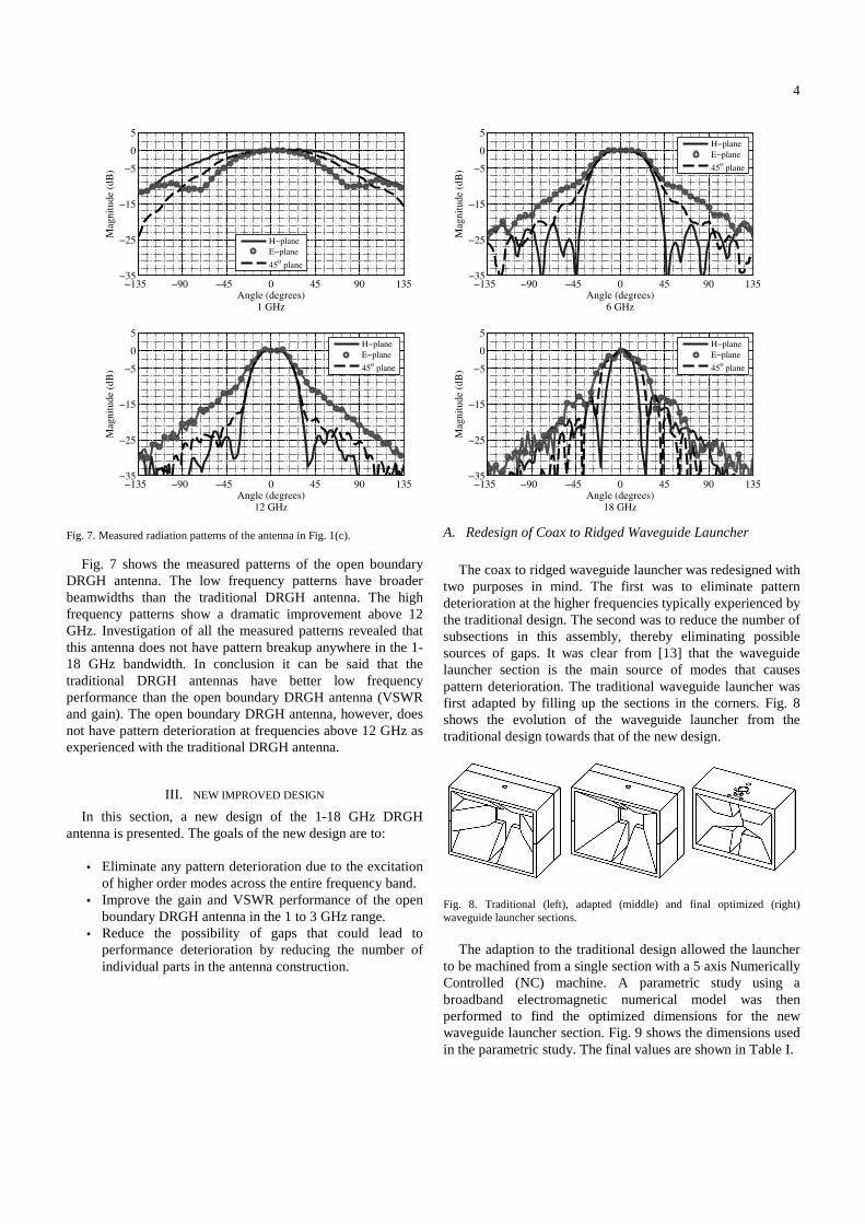
Fig. 7. Measured radiation patterns of the antenna in Fig. 1(c).
Fig. 7 shows the measured patterns of the open boundary DRGH antenna. The low frequency patterns have broader beamwidths than the traditional DRGH antenna. The high frequency patterns show a dramatic improvement above 12 GHz. Investigation of all the measured patterns revealed that this antenna does not have pattern breakup anywhere in the 1-18 GHz bandwidth. In conclusion it can be said that the traditional DRGH antennas have better low frequency performance than the open boundary DRGH antenna (VSWR and gain). The open boundary DRGH antenna, however, does not have pattern deterioration at frequencies above 12 GHz as experienced with the traditional DRGH antenna.
III. NEW IMPROVED DESIGN
In this section, a new design of the 1-18 GHz DRGH antenna is presented. The goals of the new design are to:
• Eliminate any pattern deterioration due to the excitation
of higher order modes across the entire frequency band. • Improve the gain and VSWR performance of the open
boundary DRGH antenna in the 1 to 3 GHz range. • Reduce the possibility of gaps that could lead to
performance deterioration by reducing the number of individual parts in the antenna construction.
A. Redesign of Coax to Ridged Waveguide Launcher
The coax to ridged waveguide launcher was redesigned with
two purposes in mind. The first was to eliminate pattern deterioration at the higher frequencies typically experienced by the traditional design. The second was to reduce the number of subsections in this assembly, thereby eliminating possible sources of gaps. It was clear from [13] that the waveguide launcher section is the main source of modes that causes pattern deterioration. The traditional waveguide launcher was first adapted by filling up the sections in the corners. Fig. 8 shows the evolution of the waveguide launcher from the traditional design towards that of the new design.
Fig. 8. Traditional (left), adapted (middle) and final optimized (right) waveguide launcher sections.
The adaption to the traditional design allowed the launcher
to be machined from a single section with a 5 axis Numerically Controlled (NC) machine. A parametric study using a broadband electromagnetic numerical model was then performed to find the optimized dimensions for the new waveguide launcher section. Fig. 9 shows the dimensions used in the parametric study. The final values are shown in Table I.
−135 −90 −45 0 45 90 135−35
−25
−15
−5
0
5
Mag
nit
ude
(dB
)
Angle (degrees)1 GHz
H−plane
E−plane
45o plane
−135 −90 −45 0 45 90 135−35
−25
−15
−5
0
5
Mag
nit
ude
(dB
)
Angle (degrees)6 GHz
H−plane
E−plane
45o plane
−135 −90 −45 0 45 90 135−35
−25
−15
−5
0
5
Mag
nit
ude
(dB
)
Angle (degrees)12 GHz
H−plane
E−plane
45o plane
−135 −90 −45 0 45 90 135−35
−25
−15
−5
0
5
Mag
nit
ude
(dB
)
Angle (degrees)18 GHz
H−plane
E−plane
45o plane

5
Fig. 9. Waveguide launcher dimensions used in parametric study.
TABLE I
NEW 1-18 GHZ DRGH FINAL LAUNCHER DIMENSIONS, FIG. 9
Fig. 9 reference
Description Dimension
A Launcher Cavity Width 0 mm B Launcher Cavity Height 15 mm C Vertical Flares Angle 19.29° D Horizontal Flares Angle 25.29°
With reference to Fig. 8 and Table I it can be seen that the
new waveguide launcher section is a type of hybrid between the traditional structure and a pyramidal cavity structure. By reducing the number of parts of the antenna, the manufacturing cost of the antenna could be reduced by approximately 50% compared to the traditional design.
B. Coaxial Feed
The coaxial feeding section was improved by incorporating
the bushes that form the outer conductor and termination of the inner conductor into the top and bottom ridges. This integration of the coaxial line with the top and bottom ridges eliminates the use of bushes and the resulting gaps in the feeding section of the DRGH antenna. The main disadvantage of this approach is that the top and bottom ridges are no longer identical in terms of the hole that is drilled through the ridges to accommodate the feeding structure. The hole in the top ridge has a size corresponding to a 50 Ω coaxial airline in relation to the inner conductor. The bottom ridge is machined in such a way that custom made spring fingers can be inserted into the ridge in order to capture the inner conductor with good electrical contact. Fig. 10 shows the redesigned top ridge.
Fig. 10. Redesigned top ridge with incorporated bush.
C. Ridge Curvature
Historically a short straight section followed by an
exponential profile was used for the ridge curvature of DRGH antennas. Experimentally it was found that this profile suppressed unwanted modes and provided a smooth impedance taper from the ridged waveguide to free space [14]. The traditional 1-18 GHz ridge profile is based on the 1-12 GHz Kerr DRGH profile given in [1]. The Kerr, 1-12 GHz ridge profile has a 25.4 mm straight section followed by an exponential plus linear taper. This profile is approximated by (1) where x is the axial length in mm along the horn starting at the end of the ridge's straight section and f(x) is the perpendicular distance in mm from the centre line of the horn.
xxxf 02.0)0305.0exp(635.0)( +⋅= (1)
The traditional 1-18 GHz ridge profile typically has a 13
mm straight section followed by an exponential, approximated by (2)
)0288.0exp(6.0)( xxf ⋅= (2)
It has been shown that changing the ridge profile near the
aperture of the horn can improve the aperture match and thus the VSWR [10], [11], [15]. In this study, a 3 mm straight section followed by a cubic Bezier curve was used to model the new design's ridge. The Bezier curve was used since it was found that the curve could be easily manipulated to obtain a better aperture match. A parametric study was performed to find the control points that provide the best VSWR. These dimensions can be seen in Table II. Fig. 11 shows a comparison of the ridge profiles discussed above.
TABLE II NEW 1-18 GHZ DRGH FINAL RIDGE CUBIC BEZIER CONTROL POINTS
Bezier point
Description X (mm) Y (mm)
P0 Start point 3 0.5 P1 Tangent line to start 205 0.5 P2 Tangent line to end 175.51 68.01 P3 End point 175.5 68
0 50 100 150 2000
20
40
60
80
Axial distance along horn centre line (from feedpoint) (mm)
Per
pen
dic
ula
r d
ista
nce
fro
m c
entr
e li
ne
(mm
)
Kerr horn ridge profile
Traditional horn ridge profile
New design ridge profile
Fig. 11. Ridge profile comparison.

6
D. Outline Dimensions
Fig. 12 and Table III show the outline dimensions of the
new design. It is important to note that the antenna was not scaled as in the design presented in [10]-[12]. Especially the aperture size was kept the same as that of the traditional antenna to still conform to the MIL standard specification [2]. Furthermore, the metallic grid type sidewalls were retained to ensure better gain at the low end of the band. The waveguide launcher section was able to suppress all higher order modes even without mode suppression fins or scaling the antenna.
Fig. 12. New 1-18 GHz DRGH showing outline dimensions.
TABLE III
NEW 1-18 GHZ DRGH FINAL ANTENNA DIMENSIONS, FIG. 12.
Fig. 12 reference
Description Dimension
(mm) A Aperture Width 242 B Aperture Height 136 C Waveguide axial length 168.8 D Launcher axial length 41 E Launcher Width 86 F Launcher Height 66
IV. SIMULATED AND MEASURED RESULTS
This section presents the measured and simulated results for the new design. A very accurate Method of Moments (MoM) numerical model of the DRGH antenna was implemented using the commercial software package FEKO [16] and the final meshed model is shown in Fig. 13. On a 2.5 GHz quad core processor with a Windows XP professional operating system and 8 GB RAM, the simulation typically needed 8 minutes of simulation time per frequency point.
The three dimensional radiation patterns at 18 GHz of the new design is also shown in Fig. 13. The main beam is well defined and directed on axis, indicating an absence of higher order modes.
Two prototypes of the new improved design were manufactured. Fig. 14 shows the measured boresight gains of the prototypes compared to simulated results. The gain is typically 8 to 16 dBi, similar to the traditional design and overall higher than the open boundary DRGH antenna at lower frequencies. The gain of the new antenna increases approximately linearly over most of the band and does not have a sharp gain peak or dips above 12 GHz which is typical of traditional 1-18 GHz DRGH antennas with pattern
deterioration. The simulated and measured gains are in excellent agreement.
Fig. 13. Meshed FEKO model of the new improved 1-18 GHz DRGH antenna (left). The three dimensional radiation pattern at 18 GHz (right).
1 2 4 6 8 10 12 14 16 180
2
4
6
8
10
12
14
16
18
20
Gai
n (
dB
i)
Frequency (GHz)
Simulated
Measured Antenna 1
Measured Antenna 2
Fig. 14. Boresight gain comparison between simulated and measured results.
1 2 4 6 8 10 12 14 16 180.5
1
1.5
2
2.5
3
3.5
4
4.5
5
VS
WR
Frequency (GHz)
Simulated
Measured Antenna 1
Measured Antenna 2
Fig. 15. VSWR comparison between simulated and measured results.
Fig. 15 shows the measured VSWR of the prototypes compared to simulated results. The simulated and measured VSWRs track fairly well. The variation in the high band can be due to construction variations. The VSWR of Antenna 1 is below 2:1 over most of the band with a slight increase at 18 GHz to a max of 2.1:1. Experimentally, using Antenna 2 it was found that by including a small compensating gap between the
7
N-type connector and the coaxial airline, the VSWR could be improved to be below 2:1 across the entire band. Overall, the VSWR of the new design is significantly better in comparison to the other measured antennas especially in the low band (see Fig. 4).
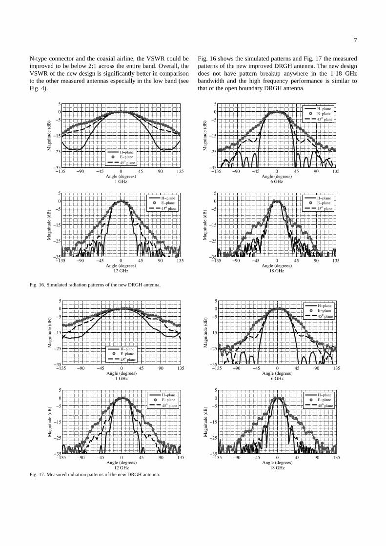
Fig. 16. Simulated radiation patterns of the new DRGH antenna.
Fig. 17. Measured radiation patterns of the new DRGH antenna.
Fig. 16 shows the simulated patterns and Fig. 17 the measured patterns of the new improved DRGH antenna. The new design does not have pattern breakup anywhere in the 1-18 GHz bandwidth and the high frequency performance is similar to that of the open boundary DRGH antenna.
−135 −90 −45 0 45 90 135−35
−25
−15
−5
0
5
Mag
nit
ude
(dB
)
Angle (degrees)1 GHz
H−plane
E−plane
45o plane
−135 −90 −45 0 45 90 135−35
−25
−15
−5
0
5
Mag
nit
ude
(dB
)
Angle (degrees)6 GHz
H−plane
E−plane
45o plane
−135 −90 −45 0 45 90 135−35
−25
−15
−5
0
5
Mag
nit
ude
(dB
)
Angle (degrees)12 GHz
H−plane
E−plane
45o plane
−135 −90 −45 0 45 90 135−35
−25
−15
−5
0
5
Mag
nit
ude
(dB
)
Angle (degrees)18 GHz
H−plane
E−plane
45o plane
−135 −90 −45 0 45 90 135−35
−25
−15
−5
0
5
Mag
nit
ude
(dB
)
Angle (degrees)1 GHz
H−plane
E−plane
45o plane
−135 −90 −45 0 45 90 135−35
−25
−15
−5
0
5
Mag
nit
ude
(dB
)
Angle (degrees)6 GHz
H−plane
E−plane
45o plane
−135 −90 −45 0 45 90 135−35
−25
−15
−5
0
5
Mag
nit
ude
(dB
)
Angle (degrees)12 GHz
H−plane
E−plane
45o plane
−135 −90 −45 0 45 90 135−35
−25
−15
−5
0
5
Mag
nit
ude
(dB
)
Angle (degrees)18 GHz
H−plane
E−plane
45o plane

8
Thus the antenna has very high gain while maintaining the same beamwidths as the open boundary DRGH antenna at high frequencies and the traditional DRGH antenna at low frequencies. The measured and simulated results compare quite well.
1 2 4 6 8 10 12 14 16 18−40
−30
−20
−10
0
Frequency (GHz)
X−
po
l re
alti
ve
to C
o−
po
l (d
B)
DRGH−0118
ETS3115
ETS3117
New design
Fig. 18. Cross-polarization performance of horn antennas measured on boresight
Figure 18 shows the measured boresight cross-polarization performance (relative to the co-polarized gain) of the antennas evaluated in this study. For all the antennas the cross-polarized component is mostly 25 dB down, except for the traditional design with dielectric sidewalls where the cross polarization performance deteriorates to about 16 dB above 17.5 GHz.
Fig. 19. Measured Co- and Cross polarized azimuth patterns of horn antennas
However, it is known that the worst case cross-polarization for DRGH antennas is at angles off boresight. Thus the co- and cross-polarized azimuth patterns were measured and compared. It was found that below 12 GHz the cross-polarized component is typically 25 dB down for all angles and all the antennas. However, at higher frequencies the cross-polarization degrades for the traditional designs. Figure 19 shows the measured results at 18 GHz. The patterns were normalized with respect to the co-polarized pattern. The cross-polarization performance of the DRGH-0118 antenna degrades significantly at angles off boresight, the same is true for the ETS3115 antenna, although less dramatic. The horns based on the new design proposed in this paper and the open boundary horn (ETS3117) have significantly better cross-polarization performance compared to the traditional horns as these horns do not suffer from higher order modes propagating anywhere in the 1-18 GHz band.
Fig. 20 shows one of the manufactured prototypes.
Fig. 20. New improved 1-18 GHz DRGH antenna.
−135 −90 −45 0 45 90 135−35
−25
−15
−5
0
5
Mag
nit
ud
e (d
B)
Angle (degrees)DRGH−0118, 18 GHz
Co−pol
X−pol
−135 −90 −45 0 45 90 135−35
−25
−15
−5
0
5
Mag
nit
ud
e (d
B)
Angle (degrees)ETS3115, 18 GHz
Co−pol
X−pol
−135 −90 −45 0 45 90 135−35
−25
−15
−5
0
5
Mag
nit
ud
e (d
B)
Angle (degrees)ETS3117, 18 GHz
Co−pol
X−pol
−135 −90 −45 0 45 90 135−35
−25
−15
−5
0
5
Mag
nit
ud
e (d
B)
Angle (degrees)New design, 18 GHz
Co−pol
X−pol

9
V. CONCLUSION
A benchmark study was performed to establish the performance of historic and current state of the art 1-18 GHz DRGH antennas. A new improved design for a 1-18 GHz wideband DRGH antenna was presented. The antenna has improved gain and VSWR performance compared to current state of the art designs. The coaxial to ridge waveguide launcher was redesigned to eliminate pattern deterioration over the entire 1-18 GHz band. The design has significantly fewer parts especially in the waveguide launcher section. This reduces the possibility of gaps between parts that could lead to performance deterioration. The aperture dimensions of the new design are identical to that of the traditional DRGH antenna, making it the only 1-18 GHz DRGH antenna without pattern breakup whose aperture dimensions comply with the requirements specified in MIL-STD-461F.
ACKNOWLEDGMENT
The authors would like to thank Saab EDS for the use of their anechoic chambers and production facilities, and EMSS for their support and insight on the use of FEKO.
REFERENCES
[1] J. L. Kerr, “Short axial length broad-band horns,” IEEE Trans. Antennas Propagat., vol. 21, no. 5, pp. 710–714, 1973.
[2] Requirements for the Control of Electromagnetic Interference Characteristics of Subsystems and Equipment, MIL-STD-461-F, Dec. 2007.
[3] American National Standard for Instrumentation-Electromagnetic Noise and Field Strength,10 kHz to 40 GHz, ANSI C63.2, 1987.
[4] Specification for radio disturbance and immunity measuring apparatus and methods – Part 1-4: Radio disturbance and immunity measuring apparatus – Ancillary equipment – Radiated disturbances, CISPR 16-1-4, 2007.
[5] C. Bruns, P. Leuchtmann, and R. Vahldieck, “Analysis and Simulation of a 1-18-GHz broadband double-ridged horn antenna,” IEEE Trans. Electromagn. Compat., vol. 45, no. 1, pp. 55–60, 2003.
[6] ____, “Comprehensive analysis and simulation of a 1-18 GHz broadband parabolic reflector horn antenna system,” IEEE Trans. Antennas Propagat., vol. 51, no. 6, pp. 1418–1422, 2003.
[7] ____, “Full wave analysis and experimental verification of a broad band ridged horn antenna system with parabolic reflector,” in IEEE Antennas and Propagation Soc. Int. Symp., 2001, vol. 4, 2001.
[8] M. Abbas-Azimi, F. Arazm, and J. Rashed-Mohassel, “Sensitivity analysis of a 1 to 18 GHz broadband DRGH antenna,” in IEEE Antennas and Propagation Society Int. Symp. 2006., pp. 3129–3132, 2006.
[9] M. Botello-Perez, H. Jardon-Aguilar, and I. G. Ruiz, “Design and Simulation of a 1 to 14 GHz Broadband Electromagnetic Compatibility DRGH Antenna,” in 2nd Int. Conf. Electrical and Electronics Engineering., pp. 118–121, 2005.
[10] V. Rodriguez, “New broadband EMC double-ridged guide horn antenna,” RF Design., pp. 44–47, 2004.
[11] M. Abbas-Azimi, F. Arazm, J. Rashed-Mohassel, and R. Faraji-Dana, “Design and optimization of a new 1-18 GHz double ridged guide horn antenna,” J. of Electromagn. Waves and Appl., vol 21, no. 4, pp. 501-516, 2007.
[12] V. Rodriguez, “Dual Ridge Horn Antenna,” U. S. Patent 6 995 728 B2, Feb., 7, 2006.
[13] B. Jacobs, J. W. Odendaal, and J. Joubert, “The Effect of Manufacturing and Assembling Tolerances on the Performance of Double-Ridged Horn Antennas”, J. of Electromagn. Waves and Appl., vol 24, no. 10, pp. 1279-1290, 2010.
[14] K. L. Walton, and V. C. Sundberg, “Broadband ridged horn design,” Microwave J., 96–101, 1964.
[15] D. Baker, and C. Van Der Neut, “A compact, broadband, balanced transmission line antenna derived from double-ridged waveguide.” Antennas and Propagat., Soc. Int. Symp., vol. 20, 1982.
[16] EM Software & Systems, FEKO User’s Manual, Suite 5.4, July 2008


![Rocky Mountain Ridged Mussel - Canada.ca · Management Plan for the Rocky Mountain Ridged Mussel in British Columbia [Final] July 2011 v RESPONSIBLE JURISDICTIONS The responsible](https://static.fdocuments.net/doc/165x107/5edb263d210a9a20dc49b473/rocky-mountain-ridged-mussel-management-plan-for-the-rocky-mountain-ridged-mussel.jpg)