
1 03 - tensor calculus 03 - tensor calculus - tensor analysis.

An image-guided method for automatically picking common-image-point gathersThomas Cullison∗ and Paul Sava, Center for Wave Phenomena, Colorado School of Mines
SUMMARY
Using common-image-point gathers (CIPs) instead ofconventional image gathers for migration velocity analy-sis is an efficient approach for analyzing migrated imagesat locations that are related to geological structures.This approach reduces computational costs and may im-prove migration velocity analysis by acounting for div-ing energy. However, manually picking CIP locations istedious and time-consuming, especially for 3D images;therefore, an automated method for picking CIPs is de-sirable. To take advantage of the potential computa-tional cost savings, CIPs should be constructed at rel-atively sparse locations throughout an image. Further-more, to facilitate improved analysis, CIPs should beconstructed along geological features. We provide a newmethod for automatically picking CIP locations fromseismic images. This method uses local image proper-ties including planarity, structure-oriented semblance,and the amplitude envelope to compute a priority-map(PMAP) of seismic images, where higher PMAP valuesindicate better CIP locations. After the priority map iscomputed, CIP locations are picked sparsely throughoutthe image using a greedy heuristic.
INTRODUCTION
Wavefield-based depth migration is commonly used forcreating accurate seismic images of complex subsurfacegeology. However, the accuracy of migrated images isstrongly related to the accuracy of the velocity mod-els that were used for migration. Therefore, generatingaccurate velocity models for migration is necessary foraccurate imaging (Gray et al., 2001).
Migration velocity analysis (MVA) is a strategy thatuses wavefields for estimating and improving the accu-racy of velocity models. In MVA, an objective func-tion is formulated after migration and image attributesare analyzed for indications of velocity model inaccura-cies (Sava and Vasconcelos, 2011). These attributes aretypically represented by image extensions using image-gathers. These gathers can be analyzed for velocity errorusing the semblance principle which states that image-gathers are flat or focused when velocity models are cor-rect (Shen et al., 2003; Stolk et al., 2005). Using thisprinciple, velocity models can be built based on objec-tive functions that optimize for image-gather featuressuch as focusing or flattening (Al-Yahya, 1989; Symes,2008).
Sava and Vasconcelos (2011) suggest that using common-image-point gathers (CIPs) instead of common-image-gathers (CIGs) for MVA has several advantages. First,
CIPs are constructed for a single image point which al-lows the image to dictate the location and sparseness ofCIPs. In contrast, for computational efficiency, CIGsare typically constructed at every depth location forfixed surface coordinates. Therefore, the image can beundersampled laterally and oversampled vertically. Sec-ond, CIPs can provide useful velocity analysis for re-flectors with arbitrary dip. In contrast, CIGs provideuseful velocity analysis only for nearly horizontal reflec-tors (Sava and Vasconcelos, 2011).
Manually picking CIP locations from complex seismicimages is a time-consuming task, especially for 3D im-ages. Therefore, if CIPs are used for MVA, it’s essentialto use an automated method for picking CIP locations.Furthermore, because features and properties of the im-age should dictate the placement of CIPs, any auto-mated method should use measurable image propertiesto guide the picking.
In this paper, we propose an automated method forpicking CIP locations from seismic images that is basedon measurable image properties. The method has twostages. In the first stage, a priority-map (PMAP) is cre-ated which assigns a value to each image location basedon measurable image properties. In the second stage, agreedy heuristic is used to automatically pick CIP loca-tions based on the PMAP values.
COMMON-IMAGE-POINT GATHERS
Common-image-point gathers (CIPs) are extended im-ages constructed at fixed positions of space, and theycan be used for MVA to analyze and correct for velocitymodel inaccuracies (Sava and Vasconcelos, 2011). How-ever, accurate velocity analysis using CIPs may onlybe applicable when several assumptions are valid. It isassumed that source and receiver wavefields as well asthe reflector can be approximated by planes within thevicinity of the CIP location. Furthermore, it is assumedthat the velocity is locally constant in this vicinity aswell. At the locations where these assumptions are in-valid, CIPs may not be usable for MVA. This includeslocations where the subsurface may have strong veloc-ity discontinuities such as at the interface of a salt body,at diffractors, or along faults because of discontinuousgeologic units. Therefore, CIPs should be constructedat locations that are along coherent reflectors that havesimple structure.
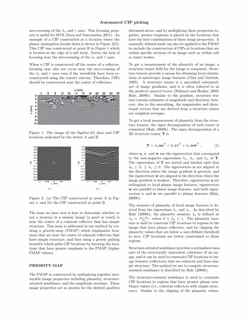
Figure 1 shows an image of the Sigsbee-2A data whichwere migrated using the correct velocity. The CIP con-structed at point A, shown in Figure 2(a), is located nearthe center of a coherent reflector that has simple struc-ture. Notice that this CIP has strong focusing near the
Automated CIP picking
zero-crossing of the λx and τ axes. This focusing prop-erty is useful for MVA (Sava and Vasconcelos, 2011). Anexample of a CIP constructed at a location where theplanar assumption breaks down is shown in Figure 2(b).This CIP was constructed at point B in Figure 1 whichis located at the edge of a salt body. Notice the lack offocusing near the zero-crossing of the λx and τ axes.
When a CIP is constructed off the center of a reflector,focusing may also not occur near the zero-crossing ofthe λx and τ axes even if the wavefields have been re-constructed using the correct velocity. Therefore, CIPsshould be constructed near the center of reflectors.
Figure 1: The image of the Sigsbee-2A data and CIPlocations indicated by the letters A and B.
(a) (b)
Figure 2: (a) The CIP constructed at point A in Fig-ure 1, and (b) the CIP constructed at point B.
The issue we have now is how to determine whether ornot a location in a seismic image (a pixel or voxel) isnear the center of a coherent reflector that has simplestructure. This issue is addressed in our method by cre-ating a priority-map (PMAP) which emphasizes loca-tions that are near the center of coherent reflectors thathave simple structure, and then using a greedy pickingheuristic which picks CIP locations by favoring the loca-tions that have greater emphasis in the PMAP (higherPMAP values).
PRIORITY-MAP
The PMAP is constructed by multiplying together mea-surable image properties including planarity, structure-oriented semblance, and the amplitude envelope. Theseimage properties act as proxies for the desired qualities
discussed above, and by multiplying these properties to-gether, greater emphasis is placed on the locations thathave the best combinations of these image properties. Amanually defined mask can also be applied to the PMAPto exclude the construction of CIPs at locations that arewithin specific sections of an image such as within saltor water bodies.
To get a measurement of the planarity of an image, astructure tensor field for the image is computed. Struc-ture tensors provide a means for obtaining local orienta-tions of anisotropic image features (Vliet and Verbeek,1995). A structure tensor is a smoothed outerprod-uct of image gradients, and it is often referred to asthe gradient squared tensor (Fehmers and Hocker, 2003;Hale, 2009b). Similar to the gradient, structure ten-sors contain estimates of magnitude and direction; how-ever, due to the smoothing, the magnitudes and direc-tional vectors that are derived from a structure tensorare weighted averages.
To get a local measurement of planarity from the struc-ture tensors, the eigen decomposition of each tensor iscomputed (Hale, 2009b). The eigen decomposition of a3D structure tensor T is
T = λuuuT + λvvvT + λwwwT , (1)
where u, v, and w are the eigenvectors that correspondto the non-negative eigenvalues λu, λv, and λw of T.The eigenvalues of T are sorted and labeled such thatλu ≥ λv ≥ λw ≥ 0. The eigenvectors u are aligned inthe direction where the image gradient is greatest, andthe eigenvectors w are aligned in the direction where theimage gradient is weakest. Therefore, eigenvectors u areorthogonal to local planar image features, eigenvectorsw are parallel to linear image features, and both eigen-vectors v and w are parallel to planar features (Hale,2009b).
The measure of planarity of local image features is de-rived from the eigenvalues λu and λv. As described byHale (2009b), the planarity measure λp is defined asλp = λu−λv
λu, where 0 ≤ λp ≤ 1. The planarity mea-
sure is used to constrain CIP locations to regions in theimage that have planar reflectors, and by clipping theplanarity values that are below a user-defined thresholdto zero, CIP locations are better constrained to theseregions.
Structure-oriented semblance provides a normalized mea-sure of the structurally dependent coherence of an im-age, and it can be used to constrain CIP locations to im-age features (reflectors) that are coherent and have sim-ple structure. The method we use to compute structure-oriented semblance is described by Hale (2009b).
The structure-oriented semblance is used to constrainCIP locations to regions that have greater planar sem-blance values (i.e., coherent reflectors with simple struc-ture). Similar to the clipping of the planarity values,
Automated CIP picking
3 km
xy
z
3 km
(a)
3 km
xy
z
3 km
(b)
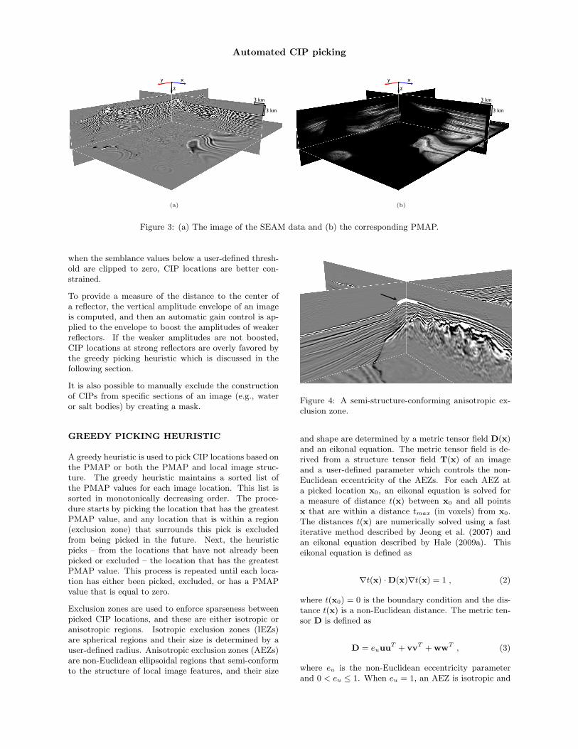
Figure 3: (a) The image of the SEAM data and (b) the corresponding PMAP.
when the semblance values below a user-defined thresh-old are clipped to zero, CIP locations are better con-strained.
To provide a measure of the distance to the center ofa reflector, the vertical amplitude envelope of an imageis computed, and then an automatic gain control is ap-plied to the envelope to boost the amplitudes of weakerreflectors. If the weaker amplitudes are not boosted,CIP locations at strong reflectors are overly favored bythe greedy picking heuristic which is discussed in thefollowing section.
It is also possible to manually exclude the constructionof CIPs from specific sections of an image (e.g., wateror salt bodies) by creating a mask.
GREEDY PICKING HEURISTIC
A greedy heuristic is used to pick CIP locations based onthe PMAP or both the PMAP and local image struc-ture. The greedy heuristic maintains a sorted list ofthe PMAP values for each image location. This list issorted in monotonically decreasing order. The proce-dure starts by picking the location that has the greatestPMAP value, and any location that is within a region(exclusion zone) that surrounds this pick is excludedfrom being picked in the future. Next, the heuristicpicks – from the locations that have not already beenpicked or excluded – the location that has the greatestPMAP value. This process is repeated until each loca-tion has either been picked, excluded, or has a PMAPvalue that is equal to zero.
Exclusion zones are used to enforce sparseness betweenpicked CIP locations, and these are either isotropic oranisotropic regions. Isotropic exclusion zones (IEZs)are spherical regions and their size is determined by auser-defined radius. Anisotropic exclusion zones (AEZs)are non-Euclidean ellipsoidal regions that semi-conformto the structure of local image features, and their size
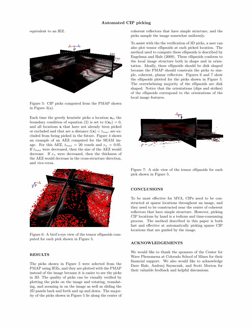
Figure 4: A semi-structure-conforming anisotropic ex-clusion zone.
and shape are determined by a metric tensor field D(x)and an eikonal equation. The metric tensor field is de-rived from a structure tensor field T(x) of an imageand a user-defined parameter which controls the non-Euclidean eccentricity of the AEZs. For each AEZ ata picked location x0, an eikonal equation is solved fora measure of distance t(x) between x0 and all pointsx that are within a distance tmax (in voxels) from x0.The distances t(x) are numerically solved using a fastiterative method described by Jeong et al. (2007) andan eikonal equation described by Hale (2009a). Thiseikonal equation is defined as
∇t(x) ·D(x)∇t(x) = 1 , (2)
where t(x0) = 0 is the boundary condition and the dis-tance t(x) is a non-Euclidean distance. The metric ten-sor D is defined as
D = euuuT + vvT + wwT , (3)
where eu is the non-Euclidean eccentricity parameterand 0 < eu ≤ 1. When eu = 1, an AEZ is isotropic and
Automated CIP picking
equivalent to an IEZ.
3 km
xy
z
3 km
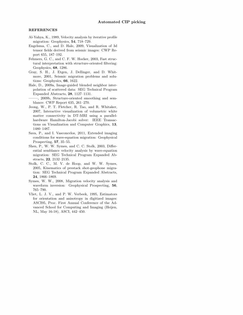
Figure 5: CIP picks computed from the PMAP shownin Figure 3(a).
Each time the greedy heuristic picks a location x0, theboundary condition of equation (2) is set to t(x0) = 0,and all locations x that have not already been pickedor excluded and that are a distance t(x) < tmax are ex-cluded from being picked in the future. Figure 4 showsan example of an AEZ computed for the SEAM im-age. For this AEZ, tmax = 20 voxels and eu = 0.05.If tmax were decreased, then the size of the AEZ woulddecrease. If eu were decreased, then the thickness ofthe AEZ would decrease in the cross-structure direction,and vice-versa.
xy z
Figure 6: A bird’s-eye view of the tensor ellipsoids com-puted for each pick shown in Figure 5.
RESULTS
The picks shown in Figure 5 were selected from thePMAP using IEZs, and they are plotted with the PMAPinstead of the image because it is easier to see the picksin 3D. The quality of picks can be visually verified byplotting the picks on the image and rotating, translat-ing, and zooming in on the image as well as sliding the2D panels back and forth and up and down. The major-ity of the picks shown in Figure 5 lie along the center of
coherent reflectors that have simple structure, and thepicks sample the image somewhat uniformly.
To assist with the the verification of 3D picks, a user canalso plot tensor ellipsoids at each picked location. Themethod used to compute these ellipsoids is described byEngelsma and Hale (2009). These ellipsoids conform tothe local image structure both in shape and in orien-tation. Ideally, these ellipsoids should be disk shapedbecause the PMAP should constrain the picks to sim-ple, coherent, planar reflectors. Figures 6 and 7 showthe ellipsoids plotted for the picks shown in Figure 5.The overwhelming majority of the ellipsoids are diskshaped. Notice that the orientations (dips and strikes)of the ellipsoids correspond to the orientations of thelocal image features.
xy z
Figure 7: A side view of the tensor ellipsoids for eachpick shown in Figure 5.
CONCLUSIONS
To be most effective for MVA, CIPs need to be con-structed at sparse locations throughout an image, andthey need to be constructed near the center of coherentreflectors that have simple structure. However, pickingCIP locations by hand is a tedious and time-consumingprocess. The method described in this paper is bothfast and effective at automatically picking sparse CIPlocations that are guided by the image.
ACKNOWLEDGEMENTS
We would like to thank the sponsors of the Center forWave Phenomena at Colorado School of Mines for theirfinancial support. We also would like to acknowledgeDave Hale, Andrzej Szymczak, and Scott Morton fortheir valuable feedback and helpful discussions.
Automated CIP picking
REFERENCES
Al-Yahya, K., 1989, Velocity analysis by iterative profilemigration: Geophysics, 54, 718–729.
Engelsma, C., and D. Hale, 2009, Visualization of 3dtensor fields derived from seismic images: CWP Re-port 655, 187–192.
Fehmers, G. C., and C. F. W. Hocker, 2003, Fast struc-tural interpretation with structure-oriented filtering:Geophysics, 68, 1286.
Gray, S. H., J. Etgen, J. Dellinger, and D. Whit-more, 2001, Seismic migration problems and solu-tions: Geophysics, 66, 1622.
Hale, D., 2009a, Image-guided blended neighbor inter-polation of scattered data: SEG Technical ProgramExpanded Abstracts, 28, 1127–1131.
——–, 2009b, Structure-oriented smoothing and sem-blance: CWP Report 635, 261–270.
Jeong, W., P. T. Fletcher, R. Tao, and R. Whitaker,2007, Interactive visualization of volumetric whitematter connectivity in DT-MRI using a parallel-hardware Hamilton-Jacobi solver: IEEE Transac-tions on Visualization and Computer Graphics, 13,1480–1487.
Sava, P., and I. Vasconcelos, 2011, Extended imagingconditions for wave-equation migration: GeophysicalProspecting, 57, 35–55.
Shen, P., W. W. Symes, and C. C. Stolk, 2003, Differ-ential semblance velocity analysis by wave-equationmigration: SEG Technical Program Expanded Ab-stracts, 22, 2132–2135.
Stolk, C. C., M. V. de Hoop, and W. W. Symes,2005, Kinematics of prestack shot-geophone migra-tion: SEG Technical Program Expanded Abstracts,24, 1866–1869.
Symes, W. W., 2008, Migration velocity analysis andwaveform inversion: Geophysical Prospecting, 56,765–790.
Vliet, L. J. V., and P. W. Verbeek, 1995, Estimatorsfor orientation and anisotropy in digitized images:ASCI95, Proc. First Annual Conference of the Ad-vanced School for Computing and Imaging (Heijen,NL, May 16-18), ASCI, 442–450.