An Image-Based System for Urban...
10
An Image-Based System for Urban Navigation Duncan Robertson and Roberto Cipolla Cambridge University Engineering Department Trumpington Street, Cambridge, CB2 1PZ, UK Abstract We describe the prototype of a system intended to allow a user to navigate in an urban environment using a mobile telephone equipped with a camera. The system uses a database of views of building facades to determine the pose of a query view provided by the user. Our method is based on a novel wide-baseline matching algorithm that can identify corresponding building facades in two views despite significant changes of viewpoint and lighting. We show that our system is capable of localising query views reliably in a large part of Cambridge city centre. 1 Introduction This research is motivated by a conceptual mobile telephone navigation application. Us- ing a handset with a built-in camera, the idea is that the user could transmit a photo- graph of his surroundings to a central computer system. Given approximate knowledge of the handset’s position (obtained by signal triangulation or similar), the system would compare the query image with a database of stored images in order to determine pose. Navigation information could then be transmitted back to the user and projected into the image. Compared with radio signal triangulation-based schemes 1 , this approach gives significantly better accuracy and determines camera orientation as well as position. 1.1 Existing Work This is essentially similar to the global localisation problem familiar from the mobile robot navigation literature. E.g. in the system described by Se et al. [11], a robot uses a calibrated trinocular stereo rig to locate visual landmarks, which are simply image fea- tures with associated 3D positions. By matching visible landmarks with previously identi- fied ones, the robot can determine its pose even if it is moved. To cope with large changes of viewpoint, image features are characterised in a way that is invariant with image rota- tion and scale [9]. This is wide-baseline matching. In related work, wide-baseline matching has been used to identify similar views using corresponding image features [10, 12]. By characterising the features in a way that is invariant with affine transformations, it is possible to identify similar views despite sub- stantial changes of viewpoint. For example, given a photograph of a building, the system 1 Existing signal triangulation-based schemes (such as http://www.cursor-system.com) claim an accuracy of a few 10’s of meters although performance may be reduced by multi-path effects in urban environments.
Transcript of An Image-Based System for Urban...

An Image-Based System for Urban Navigation
Duncan Robertson and Roberto CipollaCambridge University Engineering DepartmentTrumpington Street, Cambridge, CB2 1PZ, UK��������� �� � �
Abstract
We describe the prototype of a system intended to allow a userto navigatein an urban environment using a mobile telephone equipped with a camera.The system uses a database of views of building facades to determine thepose of a query view provided by the user. Our method is based on a novelwide-baseline matching algorithm that can identify corresponding buildingfacades in two views despite significant changes of viewpoint and lighting.We show that our system is capable of localising query views reliably in alarge part of Cambridge city centre.
1 Introduction
This research is motivated by a conceptual mobile telephonenavigation application. Us-ing a handset with a built-in camera, the idea is that the usercould transmit a photo-graph of his surroundings to a central computer system. Given approximate knowledgeof the handset’s position (obtained by signal triangulation or similar), the system wouldcompare the query image with a database of stored images in order to determine pose.Navigation information could then be transmitted back to the user and projected into theimage. Compared with radio signal triangulation-based schemes1, this approach givessignificantly better accuracy and determines camera orientation as well as position.
1.1 Existing Work
This is essentially similar to theglobal localisationproblem familiar from the mobilerobot navigation literature.E.g. in the system described by Seet al. [11], a robot uses acalibrated trinocular stereo rig to locatevisual landmarks, which are simply image fea-tures with associated 3D positions. By matching visible landmarks with previously identi-fied ones, the robot can determine its pose even if it is moved.To cope with large changesof viewpoint, image features are characterised in a way thatis invariant with image rota-tion and scale [9]. This iswide-baseline matching.
In related work, wide-baseline matching has been used to identify similar views usingcorresponding image features [10, 12]. By characterising the features in a way that isinvariant with affine transformations, it is possible to identify similar views despite sub-stantial changes of viewpoint. For example, given a photograph of a building, the system
1Existing signal triangulation-based schemes (such as http://www.cursor-system.com) claim an accuracy ofa few 10’s of meters although performance may be reduced by multi-path effects in urban environments.
described by Shaoet al. [12] can identify more photographs of the same building in alarge database of photographs obtained from a wide range of viewpoints. However, theirsystem does not determine the pose of the query.
Elsewhere, vanishing points have been used automatically to determine camera ori-entation in urban environments [2, 7, 13]. For example, Coorg and Teller [2] describe asystem that uses vanishing points to determine the orientation of dominant building fa-cades relative to a panoramic camera. However, a combination of specialist hardware isused to determine camera position, including GPS and inertial sensors. Here, only theimage data is required. Stamos and Allen [13] have also used vanishing points as partof a pose determination algorithm. However, their system requires a detailed geometricmodel obtained by laser range finding and they have only localised views in the vicinityof a single building.
1.2 Approach
By contrast to the robot localisation system described by Seet al. [11], the idea here is todetermine the pose of a query view by reference to a much simpler model comprising adatabase of rectified views of building facades. Building facades can be associated with ameaningful 3D coordinate system using readily available map data.
This is essentially an image database retrieval problem. Given a query view, the firststep is to identify a nearby database view. Then the pose of the query view is obtainedfrom the plane-to-plane transformation that relates it to the building facade. Our approachis based on a novel, wide-baseline matching algorithm that can identify correspondingbuilding facades in two views in a way that is invariant with significant changes of view-point and lighting and robust to clutter.
We describe a system that has been shown to be capable of localising query viewsreliably in a large part of Cambridge city centre.
1.3 Review and notation
Under perspective projectionu � PX, homogenous pixel coordinatesu are related tohomogenous world coordinatesX by a 3�4 projection matrixP, where� means equalityup to scale. A projection matrix may be decomposed asP � K �R �R� t � whereR is a3 �3 rotation matrix that describes camera orientation,t is the Euclidean camera position,andK is an upper triangular camera calibration matrix.
2 Wide-baseline matching
We begin by describing our wide-baseline matching algorithm. Given two views, the aimis to identify corresponding image features despite significant changes of viewpoint andlighting, and in a way that is robust to clutter.

2.1 Canonical views
The algorithm works by assuming that both views will containa dominant plane in theform of a building facade2. By determining the orientation of the camera with respect tothis plane, views may be transformed into a canonical frame by metric rectification[8](see Figure 1c).
Camera orientation is determined using the vanishing points belonging to the principalhorizontal and vertical directions that define the facade. By assuming that a significantproportion of imaged edges are aligned with these directions, the associated vanishingpoints can found automatically using the approach described by Kosecka and Zhang [7].One problem is to decide which vanishing points belong to vertical and horizontal direc-tions. To identify the vertical vanishing pointvv, it is assumed that the camera is heldapproximately ‘right way up’. Thus,vv is chosen such that the vanishing directionK�1vv
is the one most nearly parallel to the vertical�0 1 0�� . A horizontal vanishing pointvh will be associated with a perpendicular direction,i.e. it should obey the constraint�K�1vv�� �K�1vh� � 0. If more than one horizontal vanishing point is detected, we select
the one most strongly supported by line segments in the image.Without loss of generality, a local coordinate systemXFYFZF may be aligned with
the building facade defined by the vertical and horizontal vanishing points. Hence, byconsidering points at infinity corresponding to the associated vanishing directions, it issimple to derive the following constraint on the elements ofthe projection matrixPF:
�λvvv λhvh � � PF
�� 1 00 10 00 0
!"# (1)
whereλv andλh are unknown scale factors and the subscript F denotes quantities in thelocal coordinate system. WritingPF � K �RF $R�F tF �, this equation can be rearrangedand expressed in terms of camera calibration matrixK and camera orientationRF:
K�1 �λvvv λhvh � � RF
� 1 00 10 0
!# (2)
GivenK, and by exploiting the properties of a rotation matrix, equation 2 can be solvedsimply for scale factorsλv andλh, and camera orientationRF. In our conceptual mobiletelephone navigation application, we assume for the time being that it would be possible toretrieve an approximate camera calibration matrix for eachquery view from a database ofhandset models. Camera calibration can be determined in thelaboratory by photographinga suitable chessboard pattern [14].
Having determined camera orientationRF we can rectify the view [8]. This is equiv-alent to rotating the camera byRF�1 so that image plane is aligned building facade. Pixelcoordinatesuf in the rectified view may be related to pixel coordinatesu in the originalview by the following equation:
uf % Hf u (3)
2This assumption is not too restrictive in our mobile telephone navigation application, since the user caneasily be instructed to point the camera at a building.

whereHf is a 3&3 homography given byHf ' KfRF(1K(1. Here,Kf defines the originand scale of the coordinate system for the canonical view andhas the form:
Kf ' )*αf 0 u0f0 αf v0f0 0 1
+, (4)
whereu0f - .u0f v0f /0 is the origin andαf is the scale. Usually it will be convenient(i) to set theαf such that the transformationHf preserves the vertical dimension of thepixel at the centre of the original image (so the average change of scale is minimised),and (ii) to chooseu0f such that the quadrilateral boundary of the transformed image fitsin a bounding rectangle with top left corner.0 0 1/0 .
Between rectified views, a building facade will be related bya simple scale-plus-translation transformation. Thus, pixel coordinatesu1f in the first view may be related topixel coordinatesuf in the second by the following equation:
u1f - Hsuf (5)
whereHs is has the form:
Hs ' )*αs 0 u0s0 αs v0s0 0 1
+, (6)
Hereαs is the scale factor and.u0s v0s /0 is the translation in pixels.Finally, let thehorizon linebe defined as the line of intersection of the horizontal
plane defined by the camera’s optical centre with the image plane,i.e. the camera’s ‘eyelevel’. In canonical views, the horizon line is a horizontalline that passes through thepointKf .0 0 1/0 (see Figure 1).
2.2 Feature detection and characterisation
Because the canonical views are free from perspective distortion, it is simple to detect andcharacterise image features in a way that is invariant with changes of viewpoint.
Firstly, interest points are located at the maxima of the Harris corner response, whichis given by det2C3 4 0505trace2 2C3 with:
C2u 6σ 6σ 3 ' G2u 6σ 3 7 8 L2u 2u 6σ 3 LuLv 2u 6σ 3
LuLv 2u 6σ 3 L2v 2u 6σ 3 9 (7)
whereG2u 6σ 3 is a symmetric 2D Gaussian with standard deviationσ , andLu andLv
are image derivatives in theu andv directions respectively [5]. Differentiation is carriedout by convolution with the differential of another symmetric 2D Gaussian with standarddeviationσ . Here, smoothing and detection scalesσ andσ are set to 1.5 and 1.0 pixelsrespectively.
Next, local image regions in the vicinity of the interest points are characterised bysampling RGB pixel values in a square grid pattern centred onthe interest point. Goodresults have been obtained using a grid with dimensions 8&8 and a spacing of 2 pixels.Some amount of robustness to scale variation and feature localisation error is achieved bysampling the pixels from a version of the image that has been smoothed by convolutionwith a 2D Gaussian of standard deviation 2 pixels.

(a) (b) (c)
Figure 1: Obtaining canonical views. (a) Straight line segments are detected in left andright views and dominant vanishing points are recovered automatically. Line segmentsassociated with the horizontal and vertical vanishing points are shown in (b). Finally, theimages are transformed into a canonical frame corresponding to a rectified view of thedominant plane (c). In the rectified views, the horizon line is horizontal.
To account for larger changes of scale, feature detection isrepeated at multiple im-age scales like in [3]. Here, the detector described above isapplied to each level of apyramid of scaled images. The base of the pyramid is the original image and successivelevels are obtained from their predecessors by bicubic interpolation. Good results havebeen obtained using a pyramid with 5 levels, with each level 1:2 times smaller than itspredecessor.
In the subsequent matching stage (Section 2.3, below), features are compared by eval-uating the sum of squared differences between RGB pixel intensities [6]. To achieverobustness to lighting variation, pixel intensitiesIuv ; <R G B=> are first normalizedaccording to the following equation:
Iuv ; Iuv ? I@1N ∑uAv BIuv ? I B2 (8)
whereIuv is the normalised value,I is the mean, andN is the number of pixels (64 inthis case). To compare features efficiently, a coarse-to-fine approach is used (after Burtand Adelson [1]). The idea is that a large proportion of candidate matches can be rejectedwithin comparatively few operations by correlating smaller versions of the full-size tem-plate.
2.3 Feature matching
A robust, multi-scale matching approach is used, similar tothe one described by Dufour-naudet al. [3]. The idea is to match features detected at one scale in the first image with
features detected at another scale in the second, repeatingmatching for a succession ofcandidate scale relationships.
The complete matching algorithm is outlined below. Withoutloss of generality, thesecond image is considered to be the higher resolution one. In case the first image is thehigher resolution one, this sequence is repeated with the first and second images reversed:
1. Detect and characterise features in the first image at a single scales C 1. Detectand characterise features in the second image at a range of scalessC 1D2Eρ , wheredetection levelρ F G0H DDDH4I (see Section 2.2).
2. Match features detected at level 0 in the first image with features detected at acandidate levelρc in the second, whereρc F G0H DDDH4I.
3. For each candidate level, use RANSAC [4] robustly to estimate the scale-plus-translation transformationHs. Redo matching constrained by this estimate. Countmatches.
4. Finally, select the estimated transformation with the most matches.
At step 3, an initial set of correspondences could be obtained by unguided matching.However, computational efficiency can be improved by an order of magnitude by assum-ing that the views have been obtained from similar heights. This assumption is sufficientto fix one of the degrees of freedom ofHs since the horizon lines must be aligned. Thus,for a particular candidate scale relationship, the search for a match in the second imagecan be restricted to a narrow margin surrounding a 1D scan line. In consequence, theproportion of outliers is usually greatly reduced.
3 Database formulation
The basis of our global localisation system is a database of views of building facades. Atpresent, database views are obtained by photographing buildings with a hand-held digitalcamera3. Because our wide-baseline matching algorithm is effective despite significantchanges of viewpoint, a single view of each facade is sufficient to localise query viewsobtained from a wide range of viewpoints.
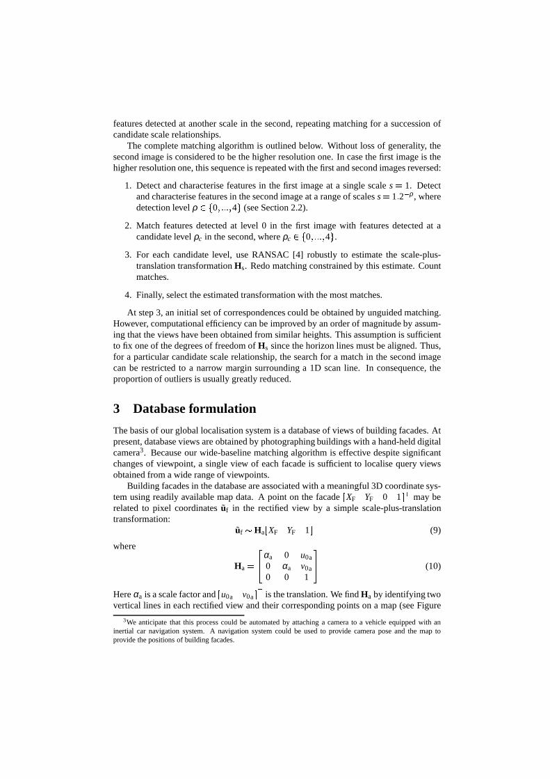
Building facades in the database are associated with a meaningful 3D coordinate sys-tem using readily available map data. A point on the facadeJXF YF 0 1KL may berelated to pixel coordinatesuf in the rectified view by a simple scale-plus-translationtransformation:
uf M HaJXF YF 1 KL (9)
where
Ha C NOαa 0 u0a0 αa v0a0 0 1
PQ (10)
Hereαa is a scale factor andJu0a v0a KL is the translation. We findHa by identifying twovertical lines in each rectified view and their corresponding points on a map (see Figure
3We anticipate that this process could be automated by attaching a camera to a vehicle equipped with aninertial car navigation system. A navigation system could be used to provide camera pose and the map toprovide the positions of building facades.

R S T S(a) (b)
UV
W XY XZ [ \
Figure 2: Building facades in the database are associated with a meaningful coordinatesystem using a map. (a) Two vertical lines are identified manually in each database view(the horizon line is also shown). (b) These lines correspondto points on the map (circles).The pointu0f is the projection of origin of the facade coordinate systemXFYFZF.
2). Thenαa ] D^d and _u0a v0a 1`a is the projection of the origin of the facade’scoordinate systemXFYF.
4 Global localisation
Having registered a set of database views, the pose of a queryview can be determinedautomatically using the homography that relates it to a building facade in the database.
Database retrieval. The first step is to identify a nearby database view. Our systemworks by conducting two-view matching between the query view and each database viewin turn using the method described in Section 2. We select thedatabase view with themost robustly estimated matches in common with the query view. By assuming that anearby database view has been obtained from a similar heightto the query view, two-viewmatching may be conducted efficiently using the scan line constraint described in Section2.3. To increase the speed of the database retrieval, rectification and feature detection isconducted in advance for database views. In our mobile telephone navigation application,prior knowledge of handset position (e.g. from cell location) could be used to constrainthe database search to a few hundreds of views.
Pose determination. Having determined the scale-plus-translation transformation Hs
that relates a building facade between the database and query views, all that remains is tofind the pose of the query. In the local facade coordinate system, the required projectionmatrix PF relates 3D points_XF YF ZF 1`a to pixel coordinatesu:
u b PF _XF YF ZF 1`a (11)
Combining equations 3, 5, and 10, it is possible to write the following relationship be-tweenXF cYF coordinates in the local coordinate system and image coordinates in theoriginal query view:
u b Hfd1HsHa_XF YF 1 `a (12)

whereHa relates points in the facade coordinate system to pixel coordinates in the rectifiedview, Hs relates the dominant plane between the query and database views, andHfe1
relates pixel coordinates in the canonical view to pixels coordinates in the original view.Comparing equation 12 with equation 11, we can see that that it defines three columns
of the projection matrixPF (up to a single unknown scale factor). SinceK andRF areknown, it is simple to recover the remaining column (up to thesame scale factor). Finally,the camera pose estimateRF, TF can be related from the facade’s coordinate system tothe map coordinate system by applying a coordinate system transformation.
5 Evaluation
To test our global localisation system, we constructed a database of views by photograph-ing all the buildings in the main shopping street in Cambridge’s city centre, as well as anumber of other buildings of interest from around the city. Our database comprises 200views in total (one per building typically) and spans at least 2 km of building facades.The area covered by the database spans an area several times greater than the positionaluncertainty associated with existing mobile positioning systems.
We also revisited the area at different times of day and obtained query views from avariety of viewpoints. Compared to the database views, the query views were obtainedat different distances from the dominant building facades and/or with different cameraorientation. Usually distance differed by at least 30% and orientation by at least 30f.There were 97 query views in total. Many of our query images contained significantclutter (pedestrians, traffic, etc.) representative of that experienced in a city centre urbanenvironment.
Using the framework described earlier, we attempted to determine the pose of eachof 97 query views. Each query took around 10 s using a 1.4 GHz desktop PC (althoughour present implementation is not especially efficient). Pose determination results wereverified by sketching building facade outlines in the database views and projecting theminto the query views using recovered homographies (since camera focal length is known,this method gives a good indication of the accuracy of the pose estimates). Overall, 93out of 97 queries were registered correctly. Representative results are shown in Figure3. Because of our robust matching strategy, usually only oneor two matches were foundbetween a query view and incorrect database views. When the system did fail, this wasbecause the database contains some photographs of buildings (or parts of buildings) thatare virtually identical to each other.
6 Conclusions
We have described the prototype of a system designed to allowa user to navigate inan urban environment using a mobile telephone equipped witha camera. The systemfacilitates efficient determination of the pose of a query view by reference to a databaseof views of building facades.
One limitation is that some buildings (and parts of buildings) are very similar. Thismeans that the system might be unable to distinguish betweensome viewpoints withoutmore information,e.g. extra query views. Another limitation is that conducting two-view matching between the query view and every nearby database view is slow. A more

127
53
(a) (b) (c)
(e) (f)
(d)
216
212
221
56
221
56
89
79
(g) (h)
50
21
189 125
101 119
Figure 3: Illustrative database retrieval results. The first rows show query views. Thesecond and third rows show the best and second best database retrieval results togetherwith the number of robustly estimated correspondences. Thefirst six images (a-f) showcorrect database retrieval results. Transferred buildingoutlines demonstrate the accuracyof the recovered pose estimates. In (g), the correct database view has been recoveredbut the scale-plus-translation transformation is wrong. In (h), the wrong view has beenretrieved because the two buildings are identical.

efficient strategy might be to use more ‘global’ image properties such as most frequentcolours to eliminate unlikely database views in advance.
In this paper, camera intrinsic parameters have been assumed known. In recent work,we have extended our system to compute the focal length and coefficients of radial distor-tion for the query view automatically using vanishing points. In future research, we willexplore the possibility of acquiring database views using acamera attached to a movingvehicle. Using an inertial car navigation system, it shouldbe possible to register viewsautomatically in the world coordinate system. Then Ordnance Survey map data could beused to provide the approximate location of dominant building facades.
References[1] P. J. Burt and E. H. Adelson. The laplacian pyramid as a compact image code.IEEE Transactions on Communications,
31(4):532–540, 1983.
[2] S. Coorg and S. Teller. Automatic extraction of texturedvertical facades from pose imagery. Technical Report TR-759,Massachusetts Institute of Technology, 1998.
[3] Y. Dufournaud, C. Schmid, and R. Horaud. Matching imageswith different resolutions. InIEEE Computer SocietyConference on Computer Vision and Pattern Recognition (CVPR’00), pages 612–618, 2000.
[4] M. Fischler and R. Bolles. Random sample consensus: A paradigm for model fitting with applications to image analysisand automated cartography.Graphics and Image Processing, 24(6):381–395, 1981.
[5] C. Harris and M. Stephens. A combined corner and edge detector. InAlvey Vision Conference, pages 189–192, 1988.
[6] T. Kanade and M. Okutomi. A stereo matching algorithm with an adapative window: Theory and experiment.IEEETransactions on Pattern Analysis and Machine Intelligence, 16(9):920–932, 1994.
[7] J. Kosecka and W. Zhang. Video compass. InEuropean Conference on Computer Vision (ECCV’02), pages 476–490,2002.
[8] D. Liebowitz, A. Criminisi, and A. Zisserman. Creating architectural models from images. InEurographics, volume 18,pages 39–50, 1999.
[9] D. G. Lowe. Object recognition from local scale-invariant features. InInternational Conference on Computer Vision(ICCV’99), pages 1150–1157, 1999.
[10] K. Mikolajczyk and C. Schmid. Indexing based on scale invariant interest points. InInternational Conference on Com-puter Vision (ICCV’01), pages 525–531, 2001.
[11] S. Se, D. Lowe, and J. Little. Mobile robot localizationand mapping with uncertainty using scale-invariant visualland-marks.International Journal of Robotics Research, 21(8):735–758, 2002.
[12] H. Shao, T. Svoboda, T. Tuytelaars, and L. Van Gool. HPATindexing for fast object/scene recognition based on localappearance. InComputer Lecture Notes on Image and Video Retrieval, pages 71–80, 2003.
[13] I. Stamos and P. K. Allen. 3D model construction using range and image data. InIEEE Computer Society Conference onComputer Vision and Pattern Recognition (CVPR’00), pages 531–536, 2000.
[14] Z. Zhang. A flexible new technique for camera calibration. IEEE Transactions on Pattern Analysis and Machine Intelli-gence, 22(11):1330–1334, 2000.