An “Ideal” Mill Inerting System - exoeng.com · An “Ideal” Mill Inerting System ... •...
27
An “Ideal” Mill Inerting System (Using Conventional Methods)
Transcript of An “Ideal” Mill Inerting System - exoeng.com · An “Ideal” Mill Inerting System ... •...
An “Ideal”Mill Inerting System
(Using Conventional Methods)
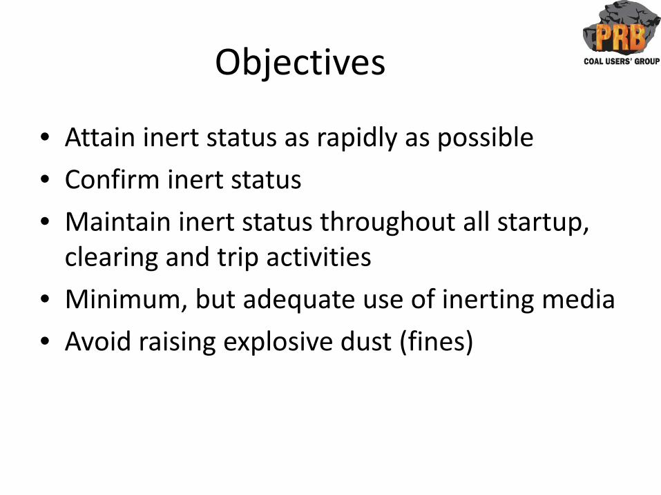
Objectives
• Attain inert status as rapidly as possible
• Confirm inert status
• Maintain inert status throughout all startup, clearing and trip activities
• Minimum, but adequate use of inerting media
• Avoid raising explosive dust (fines)
Boundaries, Comments
• Addressing medium speed vertical spindle mills, only
• Not an attempt to override manufacturer’s recommendations
• Have not addressed fire suppression• Not a “cookbook” for detailed engineering such
as fogging flow rate determination, inerting media flow rate determination, pipe sizing, nozzle sizing, nozzle location, and site specific control logic
Inerting Media
• Media selection primarily an availability and economic issue
• Steam nearly always most readily available
• Steam nearly always most economical
• Steam used by 66% of PRB Users
• This presented system will address use of steam

Premise
• Almost all inerting systems are open loop– How do we know the mill ever becomes inert?
– How do we know when the mill is inert?
– How do we know the mill remains inert as long as needed?
• Can we do a better job of economizing on the use of mill inerting media?
Testing
• Test Objectives:– Establish steam flow vs Time-to-Inert relationship
for isolated mill– Establish rate of inert decay for isolated mill– Establish steam flow required for
startup/shutdown (ie PA flow at minimum)
• Test at least one representative mill• Monitor steam flow rate, mill O2 & mill press• Use wet O2 analyzer for test
Inerting Modes
• Normal startup– Mill is clean when started
• Normal shutdown
• Post trip recovery– Mill is dirty when tripped
– May proceed to shutdown, OR
– May proceed to restart
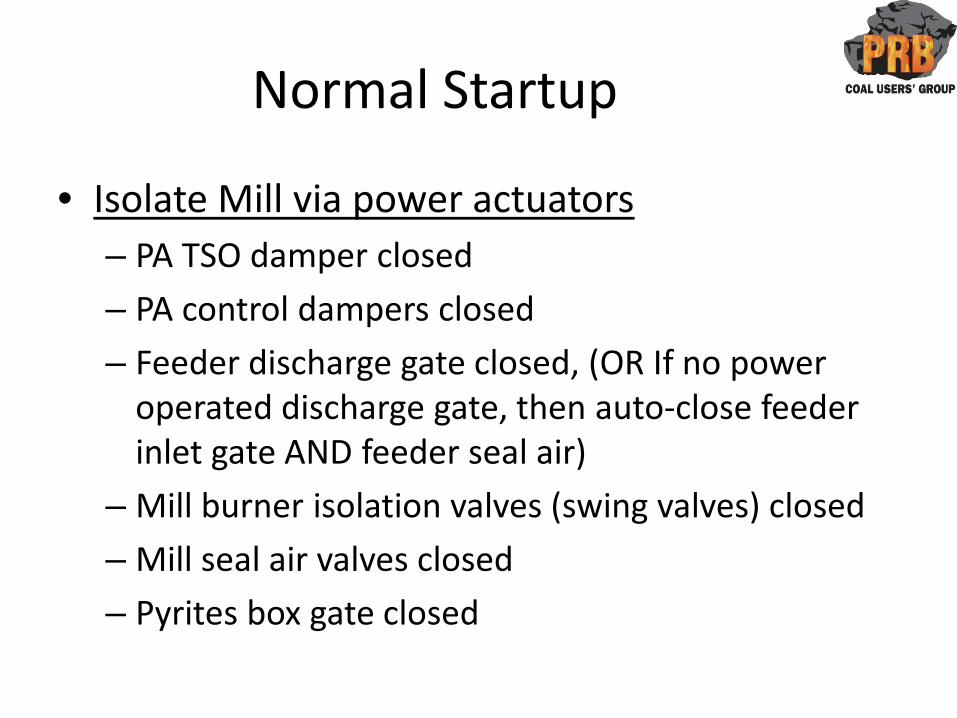
Normal Startup
• Isolate Mill via power actuators– PA TSO damper closed
– PA control dampers closed
– Feeder discharge gate closed, (OR If no power operated discharge gate, then auto-close feeder inlet gate AND feeder seal air)
– Mill burner isolation valves (swing valves) closed
– Mill seal air valves closed
– Pyrites box gate closed
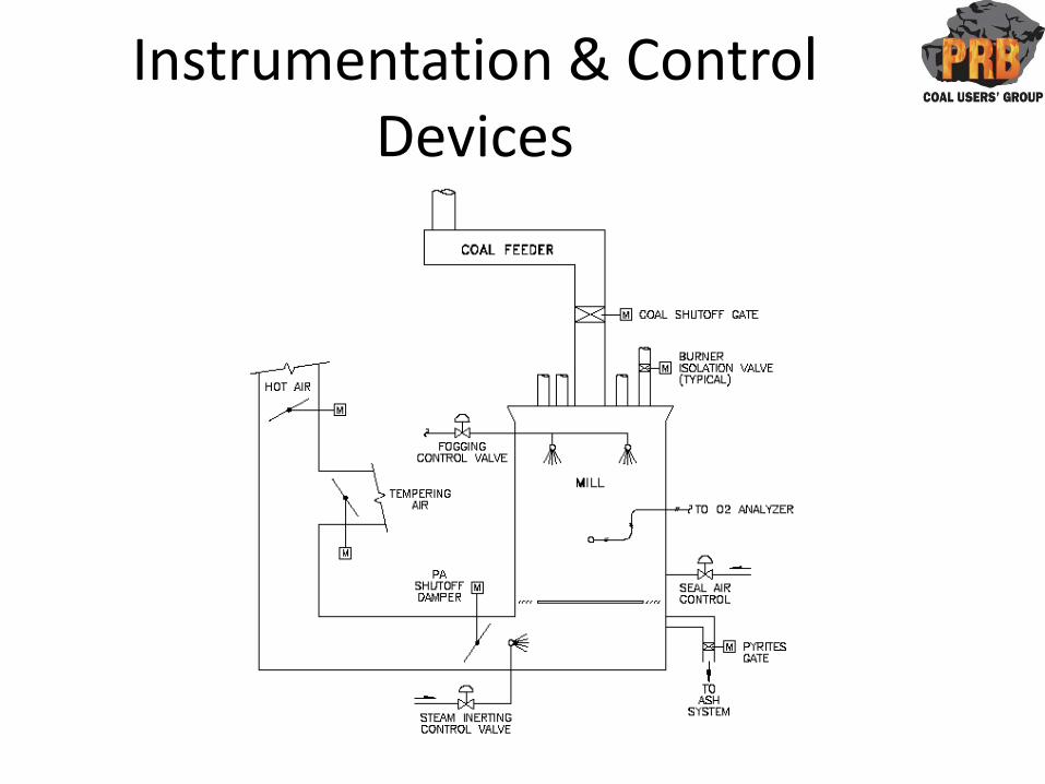
Instrumentation & Control Devices
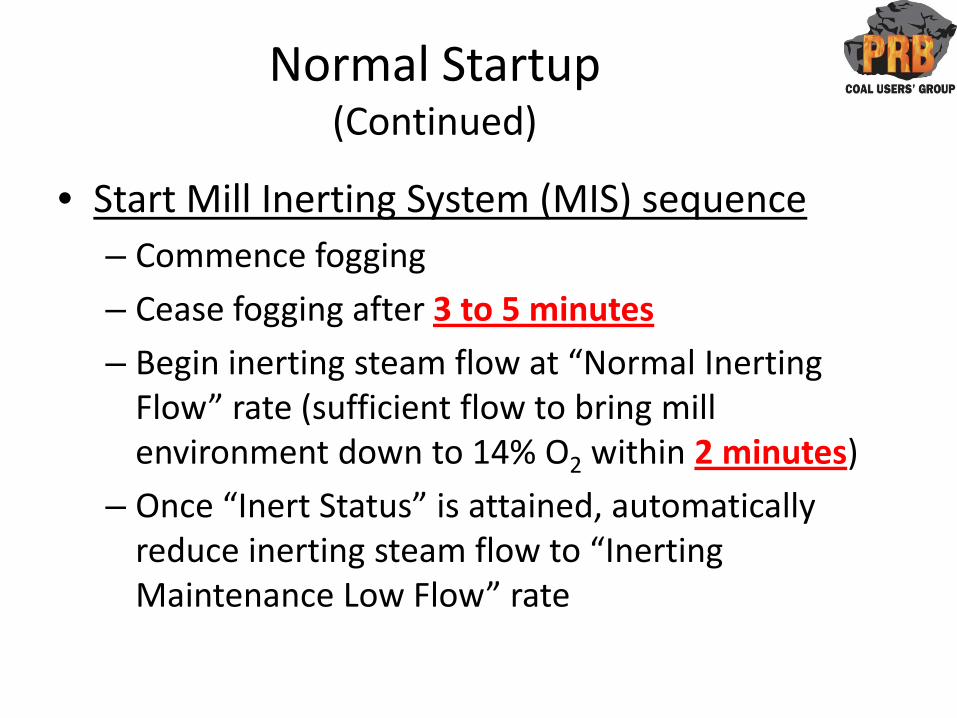
Normal Startup(Continued)
• Start Mill Inerting System (MIS) sequence– Commence fogging
– Cease fogging after 3 to 5 minutes
– Begin inerting steam flow at “Normal Inerting Flow” rate (sufficient flow to bring mill environment down to 14% O2 within 2 minutes)
– Once “Inert Status” is attained, automatically reduce inerting steam flow to “Inerting Maintenance Low Flow” rate
Normal Startup(Continued)
• Start Mill– Mill is still isolated
– MIS is still in automatic at “Inerting Maintenance Low Flow” rate, modulating as required to overcome leakage and condensation to maintain “Inert Status”
Normal Startup(Continued)
• Start coal feeder• Open burner isolation valves (swing valves)
– Mill PA control damper and temperature control dampers in control mode as recommended by mill manufacturer
– PA flow commences through the mill, thus diluting inerting media
– MIS is still in automatic. Feed forward increases inerting media flow rate to “Inerting Maintenance High Flow” rate required to maintain inert status with PA flow through the mill
• Stop MIS after mill is in successful operation as recommended by mill manufacturer
Normal Shutdown
• Reduce mill load to minimum feeder speed
• Start MIS at high flow rate required to maintain inert status with PA flow through the mill
Normal Shutdown(Continued)
• Stop feeder– MIS is still in automatic at high flow rate
• Strip mill– MIS is still in automatic at high flow rate
• Close swing valves– MIS flow rate reduces to normal as required to
overcome leakage and condensation to maintain inert status
Normal Shutdown(Continued)
• Follow manufacturer’s mill cleaning procedure (swirl, etc)
• Stop mill
• Stop MIS
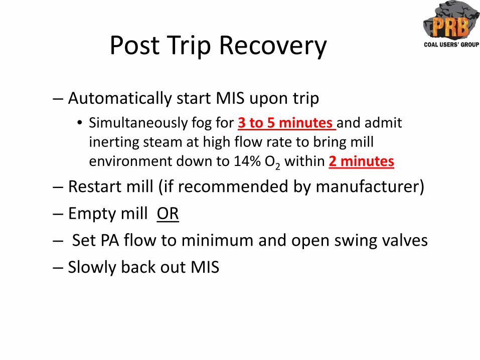
Post Trip Recovery
– Automatically start MIS upon trip• Simultaneously fog for 3 to 5 minutes and admit
inerting steam at high flow rate to bring mill environment down to 14% O2 within 2 minutes
– Restart mill (if recommended by manufacturer)
– Empty mill OR
– Set PA flow to minimum and open swing valves
– Slowly back out MIS

Instrumentation & Control Devices
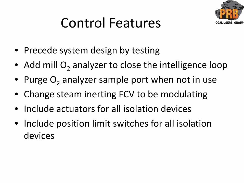
Control Features
• Precede system design by testing
• Add mill O2 analyzer to close the intelligence loop
• Purge O2 analyzer sample port when not in use
• Change steam inerting FCV to be modulating
• Include actuators for all isolation devices
• Include position limit switches for all isolation devices
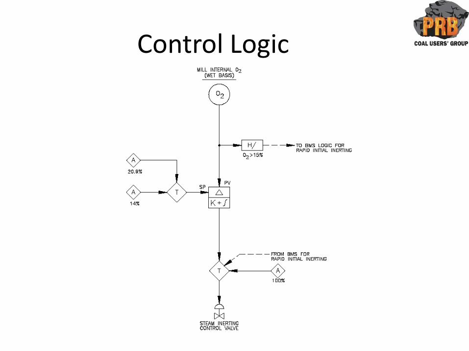
Control Logic
Design Issues-Elapsed Time to Inert
• Should inert as quickly as possible• Time-to-Inert impacted by:
– Mill size (Volume)– Completeness of isolation– Isolation integrity– Seal leakage
• Steam flow limitations:– Steam flow availability– Practical steam pipe size & line velocity– Quantity & size of inerting nozzles
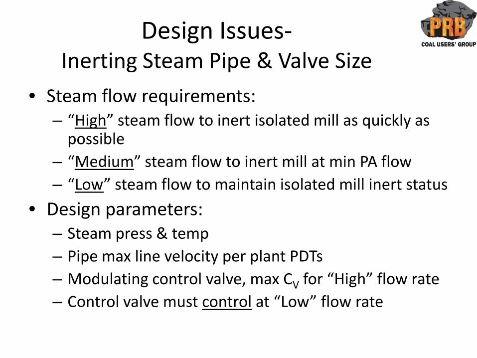
Design Issues-Inerting Steam Pipe & Valve Size
• Steam flow requirements:– “High” steam flow to inert isolated mill as quickly as
possible– “Medium” steam flow to inert mill at min PA flow– “Low” steam flow to maintain isolated mill inert status
• Design parameters:– Steam press & temp– Pipe max line velocity per plant PDTs– Modulating control valve, max CV for “High” flow rate– Control valve must control at “Low” flow rate
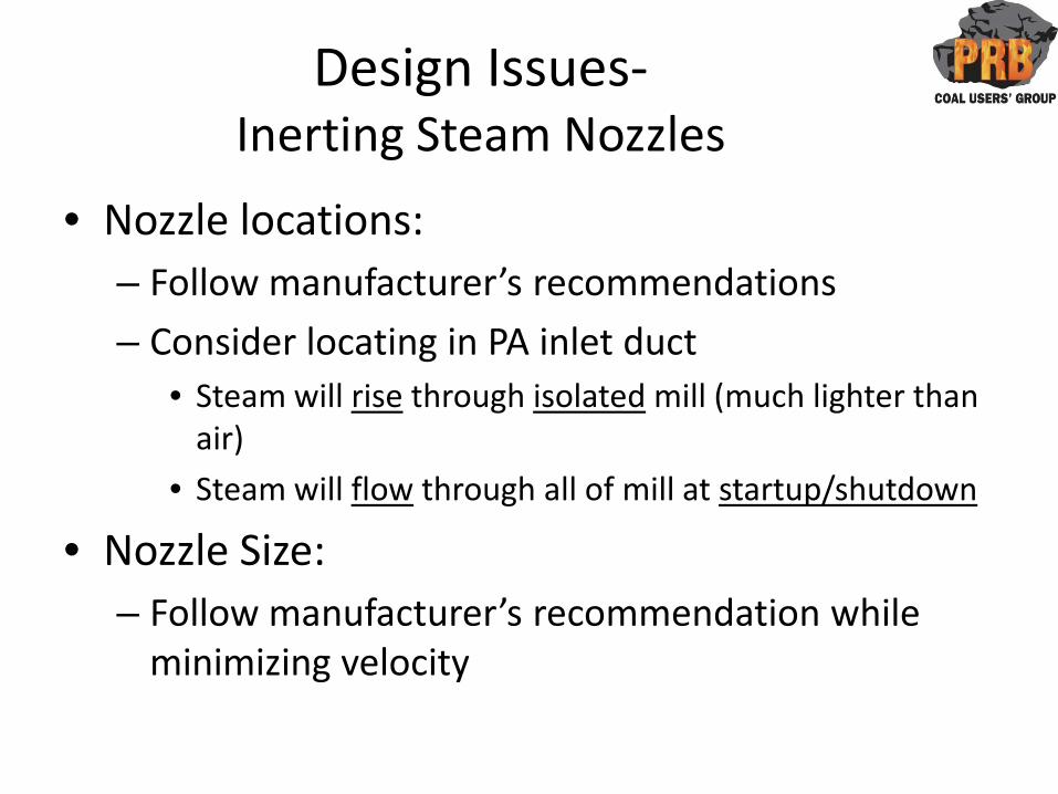
Design Issues-Inerting Steam Nozzles
• Nozzle locations:– Follow manufacturer’s recommendations
– Consider locating in PA inlet duct• Steam will rise through isolated mill (much lighter than
air)
• Steam will flow through all of mill at startup/shutdown
• Nozzle Size:– Follow manufacturer’s recommendation while
minimizing velocity
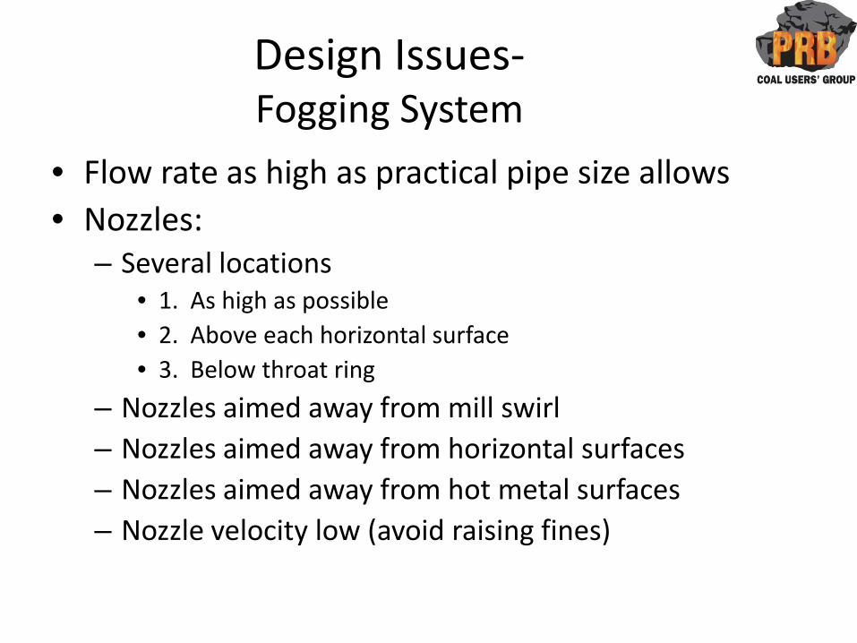
Design Issues-Fogging System
• Flow rate as high as practical pipe size allows• Nozzles:
– Several locations• 1. As high as possible• 2. Above each horizontal surface• 3. Below throat ring
– Nozzles aimed away from mill swirl– Nozzles aimed away from horizontal surfaces– Nozzles aimed away from hot metal surfaces– Nozzle velocity low (avoid raising fines)
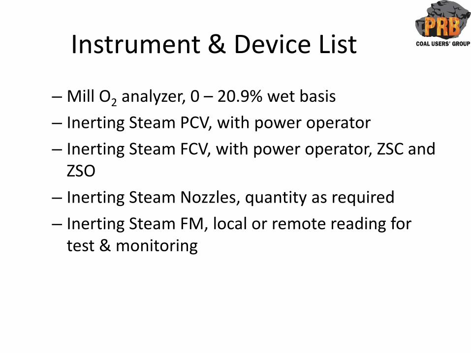
Instrument & Device List
– Mill O2 analyzer, 0 – 20.9% wet basis
– Inerting Steam PCV, with power operator
– Inerting Steam FCV, with power operator, ZSC and ZSO
– Inerting Steam Nozzles, quantity as required
– Inerting Steam FM, local or remote reading for test & monitoring
Instrument & Device List(Continued)
– Fogging Water PCV (~70 psig at nozzles)
– Fogging Water FCV, with power operator, ZSC and ZSO
– Fogging nozzles, quantity as required
– Fogging Water FM, local or remote reading for test & monitoring
Instrument & Device List(Continued)
– Primary Air Tight Shutoff Damper (PASO Damper) with actuator, position feedback and ZSC
– Hot Air Control Damper (HA Damper) with actuator and ZSC
– Tempering Air Control Damper (TA Damper) with actuator and ZSC
– Coal Feeder Shutoff Gate with actuator, ZSC and ZSO– Mill Seal Air Shutoff Valve with actuator, ZSC and ZSO– Burner Isolation Valves, with actuator, ZSC and ZSO– Pyrites Box Gate, with actuator, ZSC and ZSO

“Ideal” Mill Inerting–Last Slide
Prepared by:
Exothermic Engineering Co., LLC
Liberty, MO
www.ExoEng.com