An Experimental Study on a New Design of Double Slope Solar Still with External Flatted and
15
IOSR Journal of Mechanical and Civil Engineering (IOSR-JMCE) e-ISSN: 2278-1684,p-ISSN: 2320-334X, Volume 9, Issue 6 (Nov. - Dec. 2013), PP 40-54 www.iosrjournals.org www.iosrjournals.org 40 | Page An Experimental Study on a New Design of Double Slope Solar Still with External Flatted and Internal Parabolic Reflectors M.S.El-Sebaey 1 , Sh. Shams El-Din 2 , M. Habib 3 and A. El-Hanafy 4 1 (Mechanical Power Eng. Dept., Faculty of Engineering, Menoufia Uni., Egypt) 2 (Mechanical Power Eng. Dept., Faculty of Engineering, Menoufia Uni., Egypt) 3 (Mechanical Power Eng. Dept., Faculty of Engineering, Menoufia Uni., Egypt) 4 (Mechanical Power Eng. Dept., Faculty of Engineering, Menoufia Uni., Egypt) Abstract: The world demand for potable water is increasing steadily with growing population. Desalination using solar energy is suitable for potable water production from brackish and seawater. In this paper, we presents design, fabrication and testing of double slope solar still with external flatted and internal parabolic reflectors and also optimization of external flat reflector tilt angle for Egyptian climatic conditions. The external flat reflector tilted at (30°, 45°, 60° and 75°) on the horizontal plane. The depth of water inside basin still is 1cm. Experimental results were compared with conventional double slope solar still. Optimum tilt angle is found to be 60° with a maximum daily productivity of 9.89 lit/m 2 . Keywords : Solar desalination, Still Productivity, Performance, Heat and Mass transfer. I. INTRODUCTION Clean water is essential for good health which influences the social and economic development of any nation. People who use contaminated water are prone to waterborne diseases and they cannot effectively engage themselves in economic activities. Moreover, financial resources that could have been allocated to developmental projects are channelled to disease-curing efforts. Consequently, ill health contributes to the retardation of economic growth. The shortage of drinking water is expected to be the biggest problem of the world in this century due to unsustainable consumption rates and population growth. Pollution of fresh water resources (rivers, lakes and underground water) by industrial wastes has heightened the problem. Water is one of the most abundant resources on earth, covering three fourths of the planet’s surface. About 97% of the earth’s water is salt water in the oceans covering three fourths of the planet’s surface covering three fourths of the planet’s surface. About 97% of the earth’s water is salt water in the oceans and 3% (about 36 million km 3 ) is fresh water contained in the poles (in the form of ice), ground water, lakes and rivers, which supply most of human and animal needs. Nearly, 70% from this tiny 3% of the world’s fresh water is frozen in glaciers, permanent snow cover, ice and permafrost. Thirty percent of all fresh water is underground, most of it in deep, hard-to-reach aquifers. Lakes and rivers together contain just a little more than 0.25% of all fresh water; lakes contain most of it [1]. Water is a basic necessity for sustaining life on the earth. With the passage of time due to technological usage and their waste disposal along with ignorance of human being caused water pollution which led the world to water scarcity. Due to water pollution the surface and under ground water reservoirs are now highly contaminated. The demand of fresh water is increasing with growth in human population. To meet the demand of potable water, scientists have developed various technologies such as reverse osmosis (RO), vapour compression (VC) and electro dialysis (ED) [2]. These water purification methods are highly energy and cost intensive. It is well known that desalination plants use electrical energy which have both economical and environmental drawbacks and rely on conventional fuels [3]. Therefore a method is required to use renewable energy, low input cost and less effort for the production of potable water. Solar distillation is a thermal desalination method where solar energy is used to distill fresh water from saline and brackish water. A distillation is one of many processes available for water purification, and sunlight is one of several forms of heat energy that can be used to power that process. Sunlight has the advantage of zero fuel cost but it requires more space for its collection. It is a great practical alternative, which offers life to those regions where the lack of fresh water hinders development [4]. Solar water distillation is a solar technology with a very long history, and installations were found to be built over 2000 years ago, to produce salt rather than drinking water. An early large-scale solar still was built in 1874 to supply drinking water to mining community in Chile. Mass production occurred for the first time during the Second World War [5].
Transcript of An Experimental Study on a New Design of Double Slope Solar Still with External Flatted and

IOSR Journal of Mechanical and Civil Engineering (IOSR-JMCE)
e-ISSN: 2278-1684,p-ISSN: 2320-334X, Volume 9, Issue 6 (Nov. - Dec. 2013), PP 40-54 www.iosrjournals.org
www.iosrjournals.org 40 | Page
An Experimental Study on a New Design of Double Slope Solar
Still with External Flatted and Internal Parabolic Reflectors
M.S.El-Sebaey1, Sh. Shams El-Din
2, M. Habib
3 and A. El-Hanafy
4
1(Mechanical Power Eng. Dept., Faculty of Engineering, Menoufia Uni., Egypt) 2(Mechanical Power Eng. Dept., Faculty of Engineering, Menoufia Uni., Egypt) 3(Mechanical Power Eng. Dept., Faculty of Engineering, Menoufia Uni., Egypt) 4(Mechanical Power Eng. Dept., Faculty of Engineering, Menoufia Uni., Egypt)
Abstract: The world demand for potable water is increasing steadily with growing population. Desalination
using solar energy is suitable for potable water production from brackish and seawater. In this paper, we
presents design, fabrication and testing of double slope solar still with external flatted and internal parabolic
reflectors and also optimization of external flat reflector tilt angle for Egyptian climatic conditions. The external
flat reflector tilted at (30°, 45°, 60° and 75°) on the horizontal plane. The depth of water inside basin still is
1cm. Experimental results were compared with conventional double slope solar still. Optimum tilt angle is
found to be 60° with a maximum daily productivity of 9.89 lit/m2.
Keywords : Solar desalination, Still Productivity, Performance, Heat and Mass transfer.
I. INTRODUCTION
Clean water is essential for good health which influences the social and economic development of any
nation. People who use contaminated water are prone to waterborne diseases and they cannot effectively engage
themselves in economic activities. Moreover, financial resources that could have been allocated to
developmental projects are channelled to disease-curing efforts. Consequently, ill health contributes to the
retardation of economic growth.
The shortage of drinking water is expected to be the biggest problem of the world in this century due to
unsustainable consumption rates and population growth. Pollution of fresh water resources (rivers, lakes and underground water) by industrial wastes has heightened the problem.
Water is one of the most abundant resources on earth, covering three fourths of the planet’s surface.
About 97% of the earth’s water is salt water in the oceans covering three fourths of the planet’s surface covering
three fourths of the planet’s surface. About 97% of the earth’s water is salt water in the oceans and 3% (about 36
million km3) is fresh water contained in the poles (in the form of ice), ground water, lakes and rivers, which
supply most of human and animal needs. Nearly, 70% from this tiny 3% of the world’s fresh water is frozen in
glaciers, permanent snow cover, ice and permafrost. Thirty percent of all fresh water is underground, most of it
in deep, hard-to-reach aquifers. Lakes and rivers together contain just a little more than 0.25% of all fresh water;
lakes contain most of it [1].
Water is a basic necessity for sustaining life on the earth. With the passage of time due to
technological usage and their waste disposal along with ignorance of human being caused water pollution which
led the world to water scarcity. Due to water pollution the surface and under ground water reservoirs are now highly contaminated. The demand of fresh water is increasing with growth in human population. To meet the
demand of potable water, scientists have developed various technologies such as reverse osmosis (RO), vapour
compression (VC) and electro dialysis (ED) [2]. These water purification methods are highly energy and cost
intensive. It is well known that desalination plants use electrical energy which have both economical and
environmental drawbacks and rely on conventional fuels [3]. Therefore a method is required to use renewable
energy, low input cost and less effort for the production of potable water.
Solar distillation is a thermal desalination method where solar energy is used to distill fresh water
from saline and brackish water. A distillation is one of many processes available for water purification, and
sunlight is one of several forms of heat energy that can be used to power that process. Sunlight has the
advantage of zero fuel cost but it requires more space for its collection. It is a great practical alternative, which
offers life to those regions where the lack of fresh water hinders development [4]. Solar water distillation is a solar technology with a very long history, and installations were found to be built over 2000 years ago, to
produce salt rather than drinking water. An early large-scale solar still was built in 1874 to supply drinking
water to mining community in Chile. Mass production occurred for the first time during the Second World War
[5].

An Experimental Study on a New Design of Double Slope Solar Still with External Flatted and Internal Parabolic Reflectors
www.iosrjournals.org 41 | Page
Solar distillation systems can be small or large. They are designed either to serve the needs of single
family, producing from 1 to 4 lit of drinking water a day on the average, or to produce much greater amounts for
an entire neighborhood or village. In some parts of the world the scarcity of fresh water is partially overcome by
covering shallow salt-water basins with glass in green house- like structures. These solar energy distilling plants
are relatively inexpensive, low technology systems, especially useful where the need for small plants exists [6].
Different designs of solar still have emerged. Double slop solar still is a relatively simple device to
construct and operate. However, the low productivity of the solar still triggered the initiatives to look for ways
to improve its productivity and performance. These may be classified into passive and active methods. In this work; theoretical and experimental investigation on a new passive solar distillation system
(double slope solar with external flatted and internal parabolic reflectors) are carried out. This study optimizes
the external reflector tilt angle to found the maximum output in Egyptian climatic conditions.
II. MATERIALS AND METHODS 2.1 Experimental Set-up
2.1.1 Double Slope Solar Still
The solar still is consists mainly of a rectangular shaped with black painted basin surfaces. The still
basin is used to magnify the amount of solar energy absorbed to increase the quantity of distilled water
produced. The single basin double slope solar still has been fabricated with galvanized iron plate. The overall
size of the inner basin is 1000 mm x 500 mm x 120 mm and that of the outer basin is 1100 mm x 600 mm x 170 mm. The gap between the inner and outer basin is packed with wood chips as insulation material to reduce the
heat loss from the inner basin to the outlet. The frame of the outer basin is made of wood sheets. The top
condensing cover is consists of glasses sheets of thickness 4 mm inclined at 21° on both sides.
The schematic diagram and photograph of the double slope solar still are shown in Figures. 1a and 1b,
respectively. The condensate water is collected in the - V - and inverted - V - shaped drainage supported below
the glass lower edge on both sides. The condensate collected from both sides of the still is continuously drained
through flexible hose and stored into an external measuring jar. To keep a constant height of the water in the
basin, a small hole of 5 mm in the glass cover is provided for water inlet. Another small hole in the glass cover
is used to insert the thermocouples for measuring the seawater, base of basin; air water vapour and inner glass
cover temperatures. The holes are closed with the insulating material to avoid the heat and vapour loss.
2.1.2 Double Slope Solar Still with External Flatted and Internal Parabolic Reflectors
The double slope solar still with external flatted and internal parabolic reflectors is a concentrating
type of passive solar distillation system. The still consists of a number of mirrors to produce parabolic reflector
1200 mm long x 1500 mm wide with a focal length of 375 mm. The still condensing cover is made of 4 mm
thick simple window glass inclined at 21º with horizontal. The frame of the outer still is made of wood sheets.
The reflector was designed to concentrate the incident solar radiation on the black outside surface of the basin
.The basin area of 1000 mm x 500 mm is fabricated by using a galvanized iron sheet of 0.8 mm thickness
located on the focal line of the reflector. An external flat reflector of 1200 mm x 1500 mm was used.
The schematic diagram and photograph of modified double slope solar are shown in Figures. 2a and
2b, respectively. The glass cover allows solar radiation to pass into the still. Here, the upper blackened of the
basin absorbed part of solar radiation. The remaining amount falling on the glass cover fall on the concave
mirrors and then reflected on the bottom blackened base down.
The devices inclination angle to the horizontal plane are fixed at 30.33º N (latitude of Shebin El- Kom) to receive the maximum solar radiation during test period.
Fig .1a Schematic diagram of the double slope solar still Fig .1b Photograph of the double slope solar still
Thermocouples
Solar radiation
Insulation
Glass cover
Distillate channel

An Experimental Study on a New Design of Double Slope Solar Still with External Flatted and Internal Parabolic Reflectors
www.iosrjournals.org 42 | Page
Fig .2a Schematic diagram of double slope solar still Fig .2b Photograph of double slope solar still with external flatted and internal parabolic reflectors with external flatted and internal parabolic
reflectors reflectors
2.2 Measurements and Instrumentation
The measuring instruments used in this work include the measured weather conditions; global incident
solar radiation on a horizontal surface and ambient air temperature Ta, still productivity, inner glass cover
temperature Tg, water-vapour temperature inside each still Tv, water temperature Tw and basin temperature.
Eppley Pyranometer was used to measure the global solar radiation.
During each test, fresh water productivity is measured periodically every 60 minute using graduated
cylinder with an uncertainty of ±1 ml.
Eight Calibrated Chromel-Alumel thermocouples (Type-K) were used to measure the temperatures
inside solar stills. The thermocouples were fixed inside each still at four different positions to measure the inner basin temperature, basin water temperature, water-vapour temperature and inner glass cover temperature. The
thermocouples readings are taken using calibrated digital temperature reader (Temperature Controller Device)
with an uncertainty of ± 0.05 °C. The ambient air temperature was measured by mercury thermometer with an
accuracy of ± 0.5 °C.
III. THERMAL MODELING 3.1 External heat transfer
The external heat transfer is mainly governed by conduction, convection and radiation processes
which are independent of each other.
These processes cover the heat transfer between the solar still and the surroundings; the heat transfer
from the glass to the ambient and the heat transfer from the bottom and sides. The following heat transfer
coefficients are considered:
3.1.1 Top loss coefficient
Due to the small thickness of the glass cover (4 mm), the temperature of the glass may be assumed to
be uniform. The external convection and radiation losses from the glass cover to outside atmosphere can be
expressed as:
g cg rgq q q (1)
Where
cg cg g aq h (T T ) (2)
rg rg g aq h (T T ) (3)
The glass cover convective heat transfer coefficient (hcg) is a function of the wind velocity (v). The
value of (hcg) is given by the following empirical relation [7]:
Thermocouples
Solar radiation
Glass cover
cover Insulation
Distillate channel

An Experimental Study on a New Design of Double Slope Solar Still with External Flatted and Internal Parabolic Reflectors
www.iosrjournals.org 43 | Page
cg 0.8
[5.7 3.8 v]; v 5m / sh
[6.15 v ]; v 5m / s
(4) The glass cover radiative heat transfer coefficient (hrg) can be evaluated from the following equation
[7]:
4 4
g g sky
rg
g a
(T T )h
(T T )
(5)
sky aT T 6 (6)
By substituting (cgq ) and (
rgq ) into Eq. 1, Eq. 7 can be formulated:
g tg g aq h (T T ) (7)
Where (htg) is the total glass heat transfer loss coefficient by convection and radiation from glass to the ambient:
tg cg rgh h h (8)
3.1.2 Bottom and sides loss coefficient
Heat is also lost from the water in the basin to the ambient through bottom and side surfaces by
convection, radiation and conduction. The overall bottom loss coefficient (bU ) can be written as:
b
ins cb rb
w ins cb rb
1U
L h h1
h K h h
(9)
Where
b
ins cb rb
ins cb rb
1h
L h h
K h h
(10)
The values of ( cb rbh h ) can be obtained from Eq. 1 by substituting (v = 0) because there is no wind
velocity at the bottom of the insulation.
Similarly, the side heat loss coefficient ( eU ) can be approximated as:
ss
e b
s
AU U
A
(11)
If the side still area ( ssA ) is very small compared with ( sA ), then ( eU ) can be neglected [8].
3.2 Internal heat transfer
Heat transfer within the solar still is referred to be as the internal heat transfer; which mainly consists
of radiation, convection and evaporation that occurs between the water surface and glass cover. These three
modes of internal heat transfer are discussed as follows [9]:
3.2.1 Radiation loss coefficient
It is known that radiation heat transfer occurs between any two bodies when there is a temperature
difference between them. Considering the water surface and glass cover, the radiation between the water and the
glass can be given by:
rw rw w gq h (T T ) (12)
The radiative heat transfer is given by Stefan Boltz man's equation as below [5]:
4 4
rw eff w gq [(T 273) (T 273) ] (13)
Eliminating ( rwh ) from both the equations we get:
4 4
eff w g
rw
w g
[(T 273) (T 273) ]h
(T T )
Also, 2 2
rw eff w g w gh [(T 273) (T 273) ] (T T 546) (14)

An Experimental Study on a New Design of Double Slope Solar Still with External Flatted and Internal Parabolic Reflectors
www.iosrjournals.org 44 | Page
The effective emittance between the water surface and the glass cover can be presented by:
1
eff
w g
1 11
(15)
The values of the constants will be (w = 0.96), (
g = 0.88).
3.2.2 Convective loss coefficient
Free convection occurs across the humid air in the enclosure, due to the temperature difference between the water surface and the glass cover. The convective heat transfer rate can be obtained from the
following equation:
cw cw w gq h (T T ) (16)
The convective heat loss coefficient (cwh ) is obtained from the following expression:
ncwh xNu C[Gr Pr]
k
(17)
pCPr
k
(18)
2 3
2
g (x) ( T ')Gr
(19) To calculate the physical properties of humid air, the standard equations are used [10]. These
properties are given in Table 1.
The effective temperature difference T' is given by:
w g w
W g 3
w
(P P ) (T 273)T ' T T
268.9 10 P
(20)
From Eq. 17; it is seen that ( cwh ) depends upon two constants values (C) and (n). Various researchers
have given different values of (C) and (n) for different Grashoff number ranges.
For average spacing x 0.25 m; Dunkle [11] has taken the value of C = 0.075 and n = l/3 for Gr
4.39 x 10⁵. The expression for ( cwh ) is given as:
1/3
w g w
cw w g 3
w
(P P ) (T 273)h 0.884 (T T )
268.9 10 P
(21)
Where ( wP ) and ( gP ) are the vapour pressures at water and glass temperatures and can be expressed
by the following equations respectively:
w
w
5144P exp 25.317
273 T
(22-a)
g
g
5144P exp 25.317
273 T
(22-b) Table 1, Physical properties of humid air as function of vapour temperature [10]
Physical constants Symbol Units Expressions
Specific heat capacity PC
J/kg/K 4 2 8 3
P v v vC 999.2 0.1434T 1.101 10 T 6.758 10 T
Thermal conductivity k W/m°C 4
vk 0.0244 0.7673 10 T
Viscosity
N.S/m2 5 8
v1.718 10 4.62 10 T
Density
Kg/m3
v353.44 / (T 273.15)
Expansion factor
K-1 v1/ (T 273.15)
3.2.3 Evaporation loss coefficient
It is necessary for the evaporation loss coefficient to find out the evaporation pressure occurring inside the
still and acting on the glass and the water surfaces. Due to condensation of the rising vapour on the glass cover,

An Experimental Study on a New Design of Double Slope Solar Still with External Flatted and Internal Parabolic Reflectors
www.iosrjournals.org 45 | Page
there is heat loss by evaporation between the water surface and the glass cover. This can be expressed by the
following empirical equation [12]:
ew ew w gq h (T T ) (23)
Also, 3
ew cw w gq 16.273 10 h (P P ) (24)
Here, (ewh ) is the evaporative heat transfer coefficient and is given by:
w g3
ew cw
w g
P Ph 16.273 10 h
T T
(25)
The total heat transfer coefficient from water to glass can be obtained by the summation of all these
three heat transfer coefficients. Thus,
tw cw ew rwh h h h (26)
And tw cw ew rwq q q q (27)
3.3 Evaluation of distillate output
The hourly distillate output per m2 from the solar distillation unit can be obtained as:
ew
w
q 3600M
L
(28)
ew w g
w
h (T T ) 3600M
L
(29)
Where (L) is the latent heat of humid air in J/kg and is given by the expression [10]:
6 4
wL 3.1615 10 [1 (7.6166 10 T )] (30)
Where (wT ) is in K, and (L) is obtained also from the steam tables.
There are percentage deviations between the theoretical and experimental distillate outputs, and hence,
there is a need to modify the value of constants (C) and (n) in the expression ( nNu C[Ra] ) from which ( cwh )
is obtained. This modification, using the experimental distillate output ( wM ) is obtained as follows:
nNu C[Ra]
(31)
n ncwh xNu C[Ra] C[Gr Pr]
k
(32)
n
cw
kh C[Ra]
x
(33)
Now, 3
ew cw w gq 16.273 10 h (P P ) (34)
3 n
ew w g
kq 16.273 10 C[Ra] (P P )
x
(35)
ew
w
q 3600M
L
(36)
3 n
w w g
k 3600M 16.273 10 C[Ra] (P P )
x L
(37)
Now,
3
w g
k 3600R 16.273 10 (P P )
x L
(38)
For a given steady state conditions, the value of R is constant so,
n
wM R C[Ra] (39)
nwMC[Ra]
R
(40)
Taking the logarithm to both sides of Eq. (40) and comparing it with the straight line equation,
oy mx C (41)
An Experimental Study on a New Design of Double Slope Solar Still with External Flatted and Internal Parabolic Reflectors
www.iosrjournals.org 46 | Page
We get
w
O
My ln ,C ln C, x ln Ra
R
and m n
Using a linear regression analysis, the coefficients in Eq. (41) m and OC can be obtained by the following
expressions:
22
N xy x ym
N x x
(42)
2
O 22
y x x xyC
N x x
(43)
Where N is number of experimental observations for steady state condition and becomes N + 1 in
quasi steady state condition as in the case of this experiment.
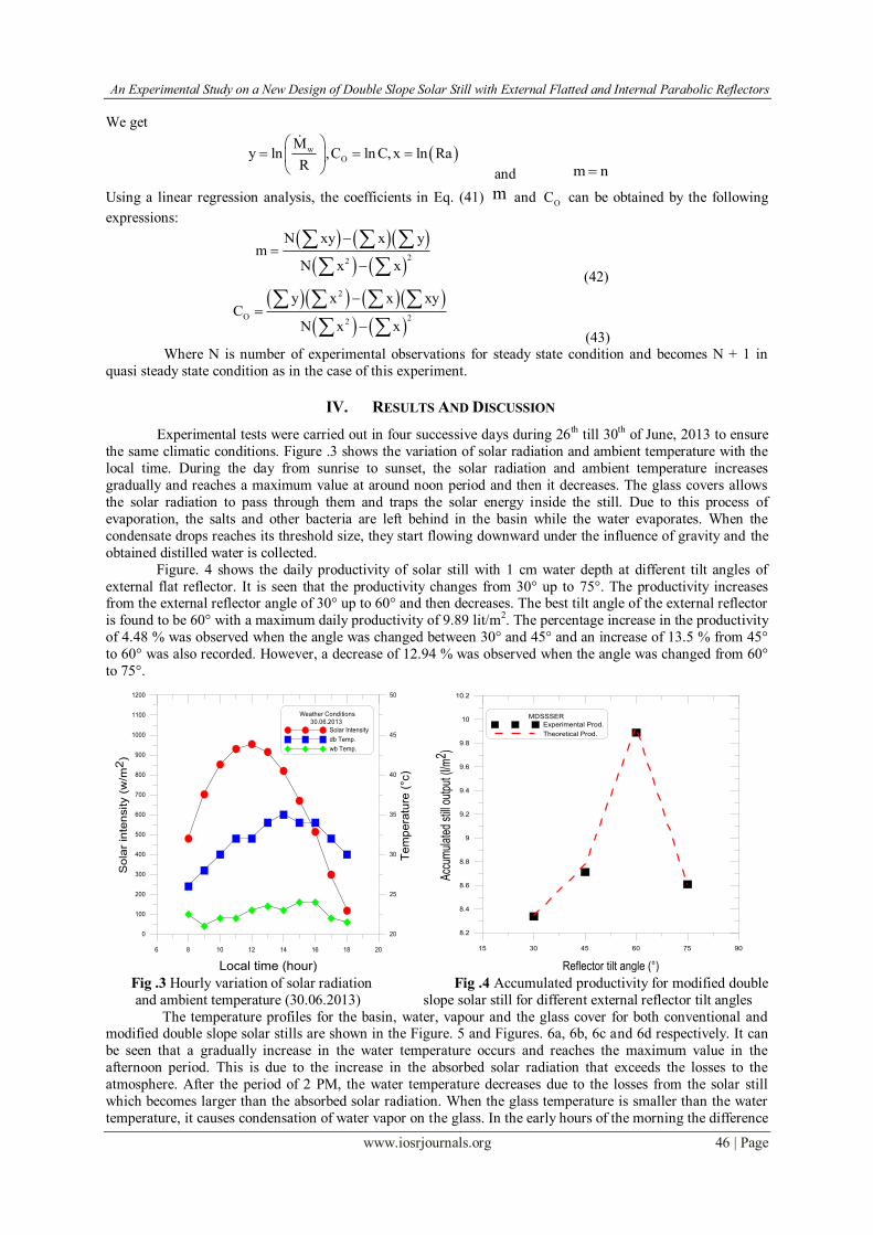
IV. RESULTS AND DISCUSSION
Experimental tests were carried out in four successive days during 26th till 30th of June, 2013 to ensure
the same climatic conditions. Figure .3 shows the variation of solar radiation and ambient temperature with the
local time. During the day from sunrise to sunset, the solar radiation and ambient temperature increases
gradually and reaches a maximum value at around noon period and then it decreases. The glass covers allows
the solar radiation to pass through them and traps the solar energy inside the still. Due to this process of
evaporation, the salts and other bacteria are left behind in the basin while the water evaporates. When the
condensate drops reaches its threshold size, they start flowing downward under the influence of gravity and the
obtained distilled water is collected.
Figure. 4 shows the daily productivity of solar still with 1 cm water depth at different tilt angles of
external flat reflector. It is seen that the productivity changes from 30° up to 75°. The productivity increases from the external reflector angle of 30° up to 60° and then decreases. The best tilt angle of the external reflector
is found to be 60° with a maximum daily productivity of 9.89 lit/m2. The percentage increase in the productivity
of 4.48 % was observed when the angle was changed between 30° and 45° and an increase of 13.5 % from 45°
to 60° was also recorded. However, a decrease of 12.94 % was observed when the angle was changed from 60°
to 75°.
6 8 10 12 14 16 18 20
0
100
200
300
400
500
600
700
800
900
1000
1100
1200
20
25
30
35
40
45
50
Weather Conditions 30.06.2013
Solar Intensity
db Temp.
wb Temp.
So
lar
inte
nsity (
w/m
2)
Te
mp
era
ture
(°c
)
Local time (hour)
15 30 45 60 75 90
8.2
8.4
8.6
8.8
9
9.2
9.4
9.6
9.8
10
10.2
MDSSSER
Experimental Prod.
Theoretical Prod.
Acc
umul
ated
stil
l out
put (
l/m2 )
Reflector tilt angle (°)
Fig .3 Hourly variation of solar radiation Fig .4 Accumulated productivity for modified double
and ambient temperature (30.06.2013) slope solar still for different external reflector tilt angles
The temperature profiles for the basin, water, vapour and the glass cover for both conventional and modified double slope solar stills are shown in the Figure. 5 and Figures. 6a, 6b, 6c and 6d respectively. It can
be seen that a gradually increase in the water temperature occurs and reaches the maximum value in the
afternoon period. This is due to the increase in the absorbed solar radiation that exceeds the losses to the
atmosphere. After the period of 2 PM, the water temperature decreases due to the losses from the solar still
which becomes larger than the absorbed solar radiation. When the glass temperature is smaller than the water
temperature, it causes condensation of water vapor on the glass. In the early hours of the morning the difference

An Experimental Study on a New Design of Double Slope Solar Still with External Flatted and Internal Parabolic Reflectors
www.iosrjournals.org 47 | Page
in glass temperature and the water temperature is smaller which causes smaller productivity. This is because the
small energy absorbed by the water at these periods.
Figures. 7a and 7b shows the variation of the water and inner glass surface temperatures for modified
solar still with external reflector angles of 30°, 45°, 60° and 75° at water depth of 1cm respectively. it is seen
that the water and inner glass surface temperatures in the morning period are maximum with external reflector
angle of 75°, showing maximum received energy and hence the maximum productivity. However, at later
periods of the day these temperatures are the maximum with external reflector angle of 60° indicating the
increase in productivity of the still compared to other external reflector angles.
6 8 10 12 14 16 18 20
20
30
40
50
60
70
80
90
DSSS26.06.2013
Base Temp.
Water Temp.
Vapour Temp.
Glass Temp.
Tem
pera
ture
(°c
)
Local time (hour)
Fig .5 Hourly variation of various temperatures of
conventional double slope solar still with local time
(29.06.2013)
6 8 10 12 14 16 18 20
20
30
40
50
60
70
80
90
MDSSSER [30°]
Base Temp.
Water Temp.
Vapour Temp.
Glass Temp.
Te
mpe
ratu
re (
°c)
Local time (hour)
Fig .6a Hourly variation of various temperatures
of modified still with external reflector angle of 30°
with local time (26.06.2013)
6 8 10 12 14 16 18 20
20
30
40
50
60
70
80
90
MDSSSER [45°]
Base Temp.
Water Temp.
Vapour Temp.
Glass Temp.
Tem
pe
ratu
re (
°c)
Local time (hour)
Fig .6b Hourly variation of various temperatures of
modified still with external reflector angle of 45°
with local time (27.06.2013)
6 8 10 12 14 16 18 20
20
30
40
50
60
70
80
90
MDSSSER [60°]
Base Temp.
Water Temp.
Vapour Temp.
Glass Temp.
Te
mpera
ture
(°c
)
Local time (hour)
Fig .6c Hourly variation of various temperatures of
modified still with external reflector angle of 60° with local time (29.06.2013)

An Experimental Study on a New Design of Double Slope Solar Still with External Flatted and Internal Parabolic Reflectors
www.iosrjournals.org 48 | Page
6 8 10 12 14 16 18 20
20
30
40
50
60
70
80
90
MDSSSER [75°]
Base Temp.
Water Temp.
Vapour Temp.
Glass Temp.
Te
mp
era
ture
(°c
)
Local time (hour) Fig .6d Hourly variation of various temperatures of modified still with external reflector angle of 75°
with local time (30.06.2013)
6 8 10 12 14 16 18 20
20
30
40
50
60
70
80
90
MDSSSER
Water Temp.
[30°]
[45°]
[60°]
[75°]
Tem
pera
ture
(°c
)
Local time (hour)
Fig .7a The variation of water temperature with
the local time for modified still at various external
reflector angles
6 8 10 12 14 16 18 20
20
30
40
50
60
70
80
90
MDSSSER
Glass Temp.
[30°]
[45°]
[60°]
[75°]
Tem
pera
ture
(°c
)
Local time (hour) Fig .7b The variation of inner glass surface temperature with the local time
for modified still at various external reflector angles
Software has been developed to calculate the values of C and n based on experimental data; namely
basin water, vapour, glass cover temperatures as well as the distillate output. The computed values of C and n
for stills are shown in Table 2. It is interesting to note that, C = 1.001368 and n=0.173616 for Garshof range of
9.8 x 10⁶ to 5.2 x 10⁷ in the case of 60° external flat reflector angle.
Tables 3a, 3b, 3c, 3d and Table 4 show the computed values of the convective heat transfer coefficients
(hcw), evaporative heat transfer coefficients (hew), radiative heat transfer coefficients (hrw) and the evaporative
transfer rate from water to the glass surface ( ewq ). The Nusselt number (Nu) and the theoretical distillate output
for modified double slope solar still with external reflector angles of 30°, 45°, 60° and 75° and conventional
double slope solar still are also presented.
Table 2, Computed values of C and n for stills
Still type
External reflector
angle
C
n
Gr range
MDSSSER 30° 1.000299 0.205281 8 x 10⁶ To 3.7 x 10
7
MDSSSER 45° 1.002664 0.191707 8.4 x 10⁶ To 3.9 x 10
7 MDSSSER 60° 1.001368 0.173616 9.8 x 10
6 To 5.2 x 10
7
MDSSSER 75° 0.9997 0.176949 1 x 10⁷ To 4.6x10
7
DSSS -------- 1.007428 0.203484 7 x 10⁵ To 4.3 x 10⁶
An Experimental Study on a New Design of Double Slope Solar Still with External Flatted and Internal Parabolic Reflectors
www.iosrjournals.org 49 | Page
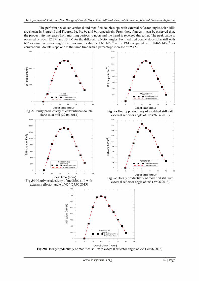
The performance of conventional and modified double slope with external reflector angles solar stills
are shown in Figure .8 and Figures. 9a, 9b, 9c and 9d respectively. From these figures, it can be observed that,
the productivity increases from morning periods to noon and the trend is reversed thereafter. The peak value is
obtained between 12 PM and 13 PM for the different reflector angles. For modified double slope solar still with
60° external reflector angle the maximum value is 1.65 lit/m2 at 12 PM compared with 0.466 lit/m2 for
conventional double slope one at the same time with a percentage increase of 254 %.
6 8 10 12 14 16 18 20
0
200
400
600
DSSS
Productivity
Experimental Prod.
Theoretical Prod.
Stil
l outp
ut (m
l/m2)
Local time (hour) Fig .8 Hourly productivity of conventional double
slope solar still (29.06.2013)
6 8 10 12 14 16 18 20
0
200
400
600
800
1000
1200
1400
1600
MDSSSER [45°] Productivity
Experimental Prod.
Theoretical Prod.
Still
ou
tput
(ml/m
2)
Local time (hour) Fig .9b Hourly productivity of modified still with
external reflector angle of 45° (27.06.2013)
6 8 10 12 14 16 18 20
0
200
400
600
800
1000
1200
1400
1600
MDSSSER [30°]
Productivity
Experimental Prod.
Theoretical Prod.
Stil
l ou
tput (m
l/m2
)Local time (hour)
Fig .9a Hourly productivity of modified still with
external reflector angle of 30° (26.06.2013)
6 8 10 12 14 16 18 20
0
200
400
600
800
1000
1200
1400
1600
1800
MDSSSER [60°] Productivity
Experimental Prod.
Theoretical Prod.
Stil
l ou
tput (m
l/m2)
Local time (hour) Fig .9c Hourly productivity of modified still with
external reflector angle of 60° (29.06.2013)
6 8 10 12 14 16 18 20
0
200
400
600
800
1000
1200
1400
1600
MDSSSER [75°]
Productivity
Experimental Prod.
Theoretical Prod.
Stil
l ou
tput
(ml/m
2)
Local time (hour)
Fig .9d Hourly productivity of modified still with external reflector angle of 75° (30.06.2013)

An Experimental Study on a New Design of Double Slope Solar Still with External Flatted and Internal
www.iosrjournals.org 50 | Page
Table 3a, Computed values of hcw, hew, hrw, Nu and theoretical distillate output for modified values of C and n
for 30° external flat reflector angle (C = 1.000299 and n=0.205281 for Garshof range of 8 x 10⁶ to 3.7 x 10⁷)
Nu qew
W/m2
hrw
W/m2 ºC
hew
W/m2 ºC
hcw
W/m2 ºC
Theo. distillate
output ml/m2
Exp. distillate
Output ml/m2
Time
28.44
31.70
32.74
33.19
32.47
32.16
31.26
30.50
29.67
28.09
229.4
511.7
676.2
821.7
860.1
793.3
636.2
472.8
303.2
139.4
6.44
6.65
6.82
7.08
7.54
7.42
7.26
6.96
6.46
5.84
31
40.93
47.96
57.87
75.45
69.59
61.18
48.75
32.96
18.84
3.329
3.768
3.917
4.004
3.975
3.932
3.804
3.659
3.487
3.210
347
780
1034
1262
1329
1223
978
723
460
209
354
784
1032
1250
1310
1240
980
724
460
206
09:00
10:00
11:00
12:00
13:00
14:00
15:00
16:00
17:00
18:00
Table 3b, Computed values of hcw, hew, hrw, Nu and theoretical distillate output for modified values of C and n
for 45° external flat reflector angle (C = 1.002664 , n=0.191707 for Garshof range of 8.4 x 10⁶ to 3.9 x 10⁷)
Nu qew
W/m2
hrw
W/m2 ºC
hew
W/m2 ºC
hcw
W/m2 ºC
Theo. distillate
output ml/m2
Exp. distillate
Output ml/m2
Time
23.29
25.85
26.43
26.64
26.45
26.43
25.73
25.12
24.60
23.37
232.3
531.9
709.5
835.9
870.4
847.7
697.2
501.0
317.9
150.1
6.58
6.93
7.22
7.50
7.70
7.66
7.56
7.13
6.56
5.94
28.33
40.61
50.68
61.01
68.54
66.74
61.16
45.13
29.43
17.06
2.754
3.097
3.212
3.274
3.282
3.270
3.173
3.044
2.901
2.683
353
815
1092
1292
1349
1313
1078
769
483
226
372
824
1070
1290
1340
1310
1050
752
470
236
09:00
10:00
11:00
12:00
13:00
14:00
15:00
16:00
17:00
18:00
Table 3c, Computed values of hcw, hew, hrw, Nu and theoretical distillate output for modified values of C and n
for 60° external flat reflector angle (C = 1.001368 , n=0.173616 for Garshof range of 9.8 x 10⁶ to 5.2 x 10⁷)
Nu qew
W/m2
hrw
W/m2 ºC
hew
W/m2 ºC
hcw
W/m2 ºC
Theo. distillate
output ml/m2
Exp. distillate
Output ml/m2
Time
17.74
19.51
20.33
20.52
20.38
20.24
19.84
19.16
18.48
18.08
301.2
602.6
873.9
1061.9
979.5
893.7
723.3
505.1
297.6
165.3
7.31
7.54
7.77
8.13
8.06
7.95
7.78
7.25
6.74
6.03
35.86
45.65
54.96
68.52
65.30
60.80
53.58
37.69
25.44
14.37
2.165
2.391
2.523
2.594
2.562
2.527
2.449
2.344
2.201
2.098
463
932
1358
1659
1528
1392
1123
778
454
249
456
916
1340
1650
1500
1386
1134
784
468
256
09:00
10:00
11:00
12:00
13:00
14:00
15:00
16:00
17:00
18:00
Table 3d, Computed values of hcw, hew, hrw, Nu and theoretical distillate output for modified values of C and n
for 75° external flat reflector angle (C = 0.9997 and n=0.176949 for Garshof range of 1 x 10⁷ to 4.6 x 10⁷)
Nu qew
W/m2
hrw
W/m2 ºC
hew
W/m2 ºC
hcw
W/m2 ºC
Theo. distillate
output ml/m2
Exp. distillate
Output ml/m2
Time
18.76
20.71
21.25
21.24
21.10
20.67
20.24
19.74
19.11
18.54
324.4
661.4
845.7
886.4
843.0
673.8
557.9
391.8
263.5
121.6
7.32
7.59
7.69
7.81
7.79
7.56
7.46
7.00
6.67
5.87
38.17
49.73
54.92
59.09
57.74
49.18
44.99
32.65
24.86
12.80
2.290
2.539
2.635
2.650
2.631
2.549
2.481
2.380
2.271
2.120
499
1024
1312
1378
1310
1043
861
600
401
183
482
1008
1330
1362
1330
1044
850
612
408
184
09:00
10:00
11:00
12:00
13:00
14:00
15:00
16:00
17:00
18:00

An Experimental Study on a New Design of Double Slope Solar Still with External Flatted and Internal
www.iosrjournals.org 51 | Page
Table 4, Computed values of hcw, hew, hrw, Nu and theoretical distillate output for modified values of C and n for
conventional double slope solar still (C = 1.007428 and n=0.203484 for Garshof range of 7 x 10⁵ to 4.3 x 10⁶)
Nu qew
W/m2
hrw
W/m2 ºC
hew
W/m2 ºC
hcw
W/m2 ºC
Theo. distillate
output ml/m2
Exp. distillate
Output ml/m2
Time
17.05
19.44
20.11
20.61
20.76
20.95
20.78
20.82
20.57
20.17
55.0
160.6
249.7
301.2
322.9
315.2
270.8
217.6
152.0
91.3
6.57
7.12
7.72
7.85
7.91
7.67
7.41
6.91
6.44
5.92
28.95
48.67
73.43
81.42
84.97
75.04
62.98
45.33
31.66
20.30
2.844
3.317
3.510
3.614
3.653
3.655
3.587
3.524
3.407
3.258
83
245
385
466
500
486
416
332
230
137
92
254
396
466
492
486
406
310
220
136
09:00
10:00
11:00
12:00
13:00
14:00
15:00
16:00
17:00
18:00
Comparisons between hourly and accumulative productivities for the two tested stills are shown in
Figures. 10a and 10b respectively. It is seen that the amount of accumulated distillate water with 60° external
reflector is higher than that of the other angles of 30°, 45°and 75° for modified double slope solar and also for
conventional double slope solar still.
6 8 10 12 14 16 18 20
0
200
400
600
800
1000
1200
1400
1600
1800
DSSS . MDSSSER
Experimental Prod.
DSSS
[30°]
[45°]
[60°]
[75°]
Still o
utp
ut (m
l/m
2)
Local time (hour)
Fig .10a Comparison of hourly experimental
productivities for two stills
6 8 10 12 14 16 18 20
0
1000
2000
3000
4000
5000
6000
7000
8000
9000
10000
11000
DSSS . MDSSSER
Experimental Accumulated Prod.
DSSS
[30°]
[45°]
[60°]
[75°]
Acc
umul
ated
stil
l out
put (
ml/m
2 )
Local time (hour)
Fig .10b Comparison of accumulated experimental
productivities for two stills
Figures. 11 and 12 illustrate the hourly variation of the heat transfer coefficients within the still
enclosure at different reflector angles. It is clear that the evaporative mass transfer rate is strongly influenced by the evaporative heat transfer coefficient and it increases when the evaporative heat transfer coefficient is
increased. This can be observed when corresponding values of Vw and hew shown in figures. 10a and 12 are
compared. It is also seen that the evaporative heat transfer coefficient has a maximum values at the noon period
and reaches to about 86.8 % of the total heat transfer coefficients, while the convective mode has a minimum
value and represents about 4.6% at the same period.
The radiative heat transfer mainly depends on water and glass temperatures. The radiative heat
transfer mode dominates at external reflector angle of 60° for all the sunshine hours. This is the reason why
Figure .13 shows the values of hrw high in comparison with other external reflector angles.
It is very interesting to note that, the value of hew is high for the external reflector angle of 30°
(Figure. 12); but the hourly productivity is low for the same period as can be seen in Figure. 10a, especially at
sunshine hours. This is because of the fact that, productivity is the product of evaporative heat transfer and the temperature difference and if either of these two quantities is low the productivity will be low.
Convective heat and mass transfer coefficients are important parameters, which are a measure of the
resistance to heat and mass transfer between the water surface and the fluid flowing over that surface. Figure. 14
shows the Nusselt number (Nu) as a function of the Grashof and Prandtl numbers (Gr.Pr); i.e., Rayleigh number
(Ra), for the various external reflector angles tested. The Nu values increases with increasing the Ra number for
all angles. The Nu decreases with increasing the external reflector tilt angle from 30° to 60°, after tilt angle 60°,
the Nu increases with increasing the external reflector tilt angle.

An Experimental Study on a New Design of Double Slope Solar Still with External Flatted and Internal
www.iosrjournals.org 52 | Page
8 10 12 14 16 18 20
1.8
2
2.2
2.4
2.6
2.8
3
3.2
3.4
3.6
3.8
4
4.2
4.4
4.6
MDSSSER [1cm]
[30°]
[45°]
[60°]
[75°]
Con
vect
ive
heat
tran
sfer
coe
ffici
ent
(w
/m2 °c
)
Local time (hour) Fig .11 Variation of convective heat transfer
coefficient (hcw) for various external reflector angles
8 10 12 14 16 18 20
5.5
6
6.5
7
7.5
8
8.5
MDSSSER [1cm]
[30°]
[45°]
[60°]
[75°]
Radia
tive h
eat tr
ansfe
r coeffic
ient
(w
/m2°c
)
Local time (hour) Fig .13 Variation of radiative heat transfer coefficient
(hrw) for various external reflector angles
8 10 12 14 16 18 20
0
10
20
30
40
50
60
70
80
MDSSSER [1cm]
[30°]
[45°]
[60°]
[75°]
Eva
pora
tive
heat
tran
sfer
coe
ffici
ent
(
w/m
2 °c)
Local time (hour) Fig .12 Variation of evaporative heat transfer
coefficient (hew) for various external reflector angles
1 10 100
10
100
MDSSSER [1cm]
[30°]
[45°]
[60°]
[75°]
Nu
(Ra)x106
Fig .14 Variation of Nusselt number with Rayleigh
number for various external reflector angles
V. CONCLUSIONS
The best external reflector angle of modified double slope solar for 1cm water depth in Egyptian
climatic conditions is 60° with a maximum daily productivity of 9.89 lit/m2.
The productivity increases by 4.48 % when the external reflector angle changes from 30° to 45° while it
increases by 13.5 % when angle changes from 45° to 60°.
The productivity decreases by 12.94 % when the external reflector angle changes from 60° to 75°.
The performance of solar stills cannot be evaluated precisely unless the values of C and n are validated
experimentally. Therefore, it is recommended that before predicting the performance parameters theoretically, an experiment may be carried out on a particular model of still for a given climatic condition to evaluate the
values of C and n.
The proposed empirical correlation obtained is 0.173616
Nu 1.001368 Ra for Garshof number ranging
from 9.8 x 10⁶ to 5.2 x 10⁷ for modified double slope solar still with external reflector angle of 60°.
An Experimental Study on a New Design of Double Slope Solar Still with External Flatted and Internal
www.iosrjournals.org 53 | Page
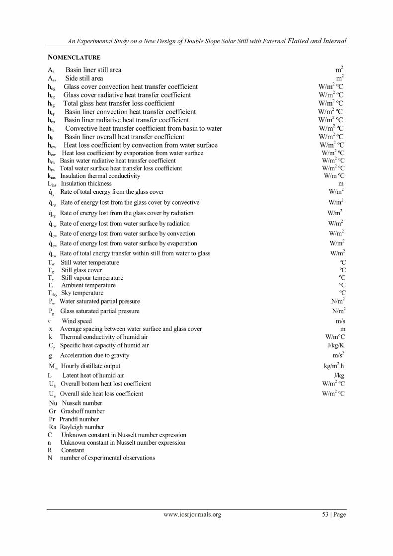
NOMENCLATURE
As Basin liner still area m2
Ass Side still area m2
hcg Glass cover convection heat transfer coefficient W/m2 ºC
hrg Glass cover radiative heat transfer coefficient W/m2 ºC
htg Total glass heat transfer loss coefficient W/m2 ºC
hcp Basin liner convection heat transfer coefficient W/m2 ºC
hrp Basin liner radiative heat transfer coefficient W/m2 ºC
hw Convective heat transfer coefficient from basin to water W/m2 ºC
hb Basin liner overall heat transfer coefficient W/m2 ºC
hcw Heat loss coefficient by convection from water surface W/m2 ºC
hew Heat loss coefficient by evaporation from water surface W/m2 ºC
hrw Basin water radiative heat transfer coefficient W/m2 ºC
htw Total water surface heat transfer loss coefficient W/m2 ºC
kins Insulation thermal conductivity W/m ºC
Lins Insulation thickness m
gq Rate of total energy from the glass cover W/m2
cgq Rate of energy lost from the glass cover by convective W/m2
rgq Rate of energy lost from the glass cover by radiation W/m2
rwq Rate of energy lost from water surface by radiation W/m2
cwq Rate of energy lost from water surface by convection W/m2
ewq Rate of energy lost from water surface by evaporation W/m2
twq Rate of total energy transfer within still from water to glass W/m2
Tw Still water temperature ºC
Tg Still glass cover ºC
Tv Still vapour temperature ºC Ta Ambient temperature ºC
Tsky Sky temperature ºC
wP Water saturated partial pressure N/m2
gP Glass saturated partial pressure N/m2
v Wind speed m/s
x Average spacing between water surface and glass cover m
k Thermal conductivity of humid air W/m°C
pC Specific heat capacity of humid air J/kg/K
g Acceleration due to gravity m/s2
wM Hourly distillate output kg/m2.h
L Latent heat of humid air J/kg
bU Overall bottom heat lost coefficient W/m2 ºC
eU Overall side heat loss coefficient W/m2 ºC
Nu Nusselt number
Gr Grashoff number
Pr Prandtl number
Ra Rayleigh number
C Unknown constant in Nusselt number expression
n Unknown constant in Nusselt number expression
R Constant
N number of experimental observations

An Experimental Study on a New Design of Double Slope Solar Still with External Flatted and Internal
www.iosrjournals.org 54 | Page
GREEK SYMBOLS
eff Effective emissivity
w Emissivity of water
g Nusselt number
Expansion factor
Stephan–Boltzman coefficient W/m2.K4
ρ Density of humid air kg/m3
Dynamic viscosity of humid air N.S/m2
ABBREVIATIONS
MDSSSER Modified Double Slope Solar Still with External Reflector ]]
DSSS Double Slope Solar Still
REFERENCES [1] Soteris A. Kalogirou., Seawater desalination using renewable energy sources. Progress in Energy and Combustion Science, 2005,
31; 242 – 281.
[2] Tiwari GN, Tiwari A., Solar distillation practice for water desalination systems. New Delhi (India): Anamaya, 2007.
[3] Kuwait Pike JG., Ground water resources development and the environment in the central region of the Arabian Gulf. Int J Water
Resources Develop; 1983, 1:115–32.
[4] A.E. Kabel, S.A. El-Agouz, Review of researches and developments on solar stills, Desalination, 2011, 276, 1–12.
[5] A.K. Tiwari, G.N. Tiwari., Effect of water depths on heat and mass transfer in a passive solar still: In summer climatic condition,
Desalination, 2006, 195, 78–94.
[6] E. Chafik., A new Type of Seawater Desalination Plants Using Solar Energy, Desalination, 2003, 156, 333-348.
[7] M. Boubekri, A. Chaker, Yield of an improved solar still : numerical approach, Energy Proscedia, 2011, 6, 610-617.
[8] Malik, M.A.S., Tiwari, G.N., Kumar, A. and Sodha, M.S., Solar Distillation, UK: Pergamon Press, 1982.
[9] Sampathkumar, K., Arjunan, T.V., Pitchandi, P. and Senthilkumar P., Active solar distillation - A detailed review, Renewable and
Sustainable Energy Reviews, 2010, Vol. 14, pp.1503–1526.
[10] G.N.Tiwari, ''Solar Energy''. Narosa Publishing House. New Delhi, 2002.
[11] Dunkle, R. V., Solar water distillation: The roof type still and a multiple effect diffusion still. Int. Development in Heat Transfer,
ASME, Proc. Int. Hear Transfer, Part V, University of Colorado, 1961, p. 895.
[12] G.N.Tiwari, A.Minocha, P.B. Sharma, M. Emran Khan, Simulation of convective mass transfer in a solar distillation process.
Energy Convers. Mgmr, 1997, Vol. 38, No. 8, pp. 761-770.


![CareNet Fall2011 [PRES 03] Final Presentation Flatted](https://static.fdocuments.net/doc/165x107/577d22d21a28ab4e1e98518e/carenet-fall2011-pres-03-final-presentation-flatted.jpg)