An Evaluation and Redesign of the Conflict …...NASA/TM--1998-112227 J An Evaluation and Redesign...
28
NASA/TM--1998-112227 J An Evaluation and Redesign of the Conflict Prediction and Trial Planning Planview Graphical User Interface Irene V. Laudeman Ames Research Center, Moffett Field, California Connie L. Brasil San Jose State University, San Jose, California Philippe Stassart Sterling Software, Redwood Shores, California National Aeronautics and Space Administration Ames Research Center Moffett Field, California 93035-1000 i April 1998
Transcript of An Evaluation and Redesign of the Conflict …...NASA/TM--1998-112227 J An Evaluation and Redesign...

NASA/TM--1998-112227
J
An Evaluation and Redesign of the Conflict Prediction and
Trial Planning Planview Graphical User Interface
Irene V. Laudeman
Ames Research Center, Moffett Field, California
Connie L. Brasil
San Jose State University, San Jose, California
Philippe Stassart
Sterling Software, Redwood Shores, California
National Aeronautics and
Space Administration
Ames Research Center
Moffett Field, California 93035-1000
i
April 1998

ii2_!_iii_i_ 'ii_ii___i?:!!?12i_,__i!i_ii_i?_!i!i_'il;i!i!:i_!i_:!'i_ii!_i%__i_i!ii___?_ii_5U_' _2!'¸ili_ii_iiii_:!¸¸:_ _i_i#i!_:<!ii!_i_!!ii__'i5; ¸¸_'? ?i_?!iii!¸ ?ii, _iiii_ii_i!:!;!_:i__?<_: '_2 ?!:;ii127_!i!!:_ili!!!!_i!_i_i!i!i!!!?ii!iiiiiiii!_!!i!!!_!i_iii_il;i!!_ill_iiiiii!_iii_iiii!iiiiiii!ii!:_!!iiiii_ii!!iiii!?i_!i_ii!;ii!i!!!!_!ii!!iii!iiiiilliiii!!_i!ii;ii!!!i!ii!_!!_!!_i_iii!_!_i_!_!!_i!_!_i_!ii_i_!_ii_i_ii!!!_i_!!_!iiii!i_ii_i_!i_!ii_i!iii_i!!i_iii_ii_ii_!_ii_iii_i!iii_iiiiiiiiiii_iii_iiiJiiiiiiiiiii_ii_ii_iiiiiiiiii_iii_iiiiiiiiiii!_
Acknowledgments
The authors would like to acknowledge the extensive PGUI design input provided by
all of the members of the Ames Research Center CPTP Tool Team led by David McNally
and the Software Development Team led by Michelle Eshow.
NASA Center for Aerospace Information
800 Elkridge Landing Road
Linthicum Heights, MD 21090-2934Price Code: A03
Available from:
National Technical Information Service
5285 Port Royal Road
Springfield, VA 22161Price Code: A03

An Evaluation and Redesign of the Conflict Prediction and
Trial Planning Planview Graphical User Interface
IRENE W. LAUDEMAN, CONNIE L. BRASIL,* AND PHILIPPESTASSART"
Ames Research Center
Summary
The Planview Graphical User Interface (PGUI) is the
primary display of air traffic for the Conflict Prediction
and Trial Planning function of the Center TRACON
Automation System. The PGUI displays air traffic infor-
mation that assists the user in making decisions related to
conflict detection, conflict resolution, and traffic flow
management. The intent of this document is to outline
the human factors issues related to the design of the con-
flict prediction and trial planning portions of the PGUI,
document all human factors related design changes made to
the PGUI from December 1996 to September 1997, and
outline future plans for the ongoing PGUI design.
Introduction
The Conflict Prediction and Trial Planning (CPTP)
function has been implemented as a software process
within the Center TRACON Automation System
(CTAS). The CTAS system provides real-time informa-
tion and advisories to air traffic controllers to help them
improve the efficiency of the airspace system. CPTP uses
the trajectory synthesis capability of CTAS to generate
predicted route trajectories for the conflict search and trial
planning processes (ref. 1).
The purpose of this memorandum is to address the design
of CTAS Planview Graphical User Interface (PGUI) ele-
ments used in the CPTP functionality. The basic PGUI
display included a scaleable representation of the airspace
with jet routes, waypoints, sector boundaries, and aircraft
symbols with their corresponding flight data blocks
(FDBs). As the conflict prediction capability was insti-
tuted within the CTAS system, a conflict list displaying
the aircraft pairs predicted to be in conflict and a limited
graphical representation of conflict geometry was added tothe PGUI.
The PGUI also displayed several large panels (accessed via
functions keys) for setting the conflict probe parameters as
well as all the other PGUI parameters. All of the setup
* San Jose State University, San Jose, California.+ Sterling Software, Redwood Shores, California.
panels and functions of the PGUI had been designed as the
sole engineering prototype interface for the CTAS func-
tionality. As with most engineering prototypes, it was
not, nor should it have been, an interface appropriate for
use by an end user. This document outlines the process by
which the engineering CTAS PGUI was evolved into a
PGUI more appropriate for use by an end user.
Desired CPTP PGUI Capability
The human factors team conducted a preliminary famili-
arization and evaluation process during which a number
of broad design issues were identified. The human factors
concerns related to the CPTP PGUI design were asfollows"
1. Color
a. A color use philosophy did not exist.
b. Color was not consistent.
c. Color was used extensively and somewhat
randomly, thus diluting the impact of its usage.
d. Color use did not address the issue that control-
lers are not currently screened for color blindness.
e. Perceptually problematic colors such as saturated
reds and blues were widely used.
f. Text and graphical information was generally
presented in light shades against a black
background.
,, There was a hardware limitation of eight bit colorand a software limitation of a three level color
scheme with only three top level colors.
2. Display parameters
a. No philosophy regarding how and when the
PGUI should constrain the user regarding setup
of system parameters.
b. Large display setup differences were commonacross users, thus confounding some of the
computer human interface (CHI) issues.

3. Globaldisplaya. Globalcommandsforfunctionssuchastrend
vectors,flightdatablocks,rangetings,andrange/bearingrequireddifficulttorecallkeyboardentries.
b. Activeaircraftinputssuchasspeed,altitude,androutechangesweredifficulttomake.
c. Trackhistorieswerenotdisplayedinaformatthatusedadequateupdateratesandsymbology.
ck Aircraftsymbolsweredisplayedusingnon-standardtextsymbology.
e. Zoomandcenteringfunctionswereverydifficulttouse,requitingexcessivekeyboardentries, a.
f. Generalsetupfunctionalitywasdispersedthroughoutavarietyoffunctionkeypanels.
g. Helpfunctionwaslimited,outdated,andhardtounderstand.
4. Conflictdetectiongraphics
a. Minimal_aphicaldisplayofconflictinforma-tionmadeit difficultforausertodeterminewhichaircraftwereinconflictandwhattheconflictgeometrywas.
b. Limitedtextinformationfurthercomplicatedtheconflictdetectiontask.
5. Conflictresolution
a. Provisionofonlyonetrajectoryperaircraftresultedinaninabilitytodisplayanactivetrajectoryduringtrialplanning,resultinginalossofsituationawareness.
b. Complexanddifficulttorecallkeyboardentrieswererequiredforactiveinputsforconflictresolution.
c. Noeasilyidentifiableway(graphicortextual)todeterminewhetheraconflictresolutionhasbeenidentified.
d. Modeawarenessofactiveversustrialplanmodeswasnonexistent.
6. Text/Graphicspresentationofinformation
a. Noreasonedapproachtouseoftabularversusgraphicaldisplayofinformation.
b. Initialdisplaywasheavilybiasedtowardtextualpresentationofinformation.
c. Graphicalrepresentationwasunclearandhardtounderstand.
7. Occlusionof traffic display
a. Large setup panels and pop-up windows occlude
the traffic display at the start of operation.
b. Conflict prediction list can occlude traffic display
during system use.
8. PGUI element update rates
a. Various display elements update at obviouslydifferent rates.
b. No indication to the user of any of the update ratevalues.
9. PGUI CPTP user documentation
User manual was minimal, outdated, andinaccurate.
b. No training material.
PGUI Design Approach
It is relatively easy to provide design suggestions in an
ideal world of limitless resources. The more challenging
situation is the application of sound principles in an
environment that demands constant compromise in orderto meet resource constraints and the limitations of exist-
ing hardware and software architecture. Decisions of this
sort were and are made on a daily basis during PGUI (and
all CTAS related) design and implementation processesand required knowledge of system hardware and software
as well as general human factors principles.
It is important to realize that in the development of an
automated system, an engineering interface will evolve
that meets the initial prototyping needs of the researchers
(the PGUI as it existed in November 1996 was such an
engineering interface). The use, and therefore the design,
of an engineering interface is likely to be quite different
from the kind of CHI that will be demanded by anend user.
There are principles of design that can be applied in the
development of an end user CHI and it is important to
realize that these principles might conflict with the
personal preferences of individual researchers who are
likely to have adapted to the engineering interface. It isalso important to note that, while end user input is quite
important in CHI design, end users are not qualified inter-
face designers. An interface design will serve its purpose
most effectively if it is designed using basic human per-
formance and design principles as well as domain specific
expert input and engineering expertise. The design process
used in the implementation of the PGUI changes docu-mented here was arrived at through an interdisciplinary and

....?!_?i, _ i...... ¸¸_¸¸_ _,_................___iii_''¸¸i:¸_i!?_ii_i!!i!i_'::i!_¸ii_??_:__:_i'_ _'i!i_'i!_i_ii!i'!'_!'_!:i_ii_i _i??i___iii/i_/1%_ _i_/!i!__ ....._?_ _ii?i!i_iii_!_i? !,iii_iii!ili!ill!!i!i!!_iiii_i_!!!iii!i_i__i_!_i_i_!i!i_!_!iii_i!_i!!_!_!!!_!_!!_i!!_i_!i_!_i!ii?!_!!!_iiii__!ii_iiii_iiii_i!_!!ii!i!i_i_i_!iiiii!_!_i_ii_ii!ii_!i!_i_iiiiiJ_!_ii_ii_i!i_!i_i!_iiii_i_i_iiiiiii_i_ii_iiiii!i_iiii_i_iii_ii_ii_!!ii_!!ii_!!_!iiii!iiiii_!iii!i_i_i!iii_iii_iiii_ii_i_iii_i_iii!iiiii_iiiiiiiiiiiii_ii_i_iiiiii_iiii_ii_i_iiiiii_iiiiiii_i_!iiiiiiiiiiiiiiiiii_iiiii_iiiiiiiiiiiii
highly interactive and iterative process that included input
from human factors, software development, and domain
experts.
The following is a summary of the design changes that
were made in response to the PGUI human factorsevaluation. Each item is referenced to the human factors
concerns listed in the Desired Capability section above.
Following this section is a complete history of the
changes made to the CPTP PGUI that will provide thereader with much more detailed information about each
of the design changes noted here.
Color Redesign of PGUI
(1a-g) Development of a new color design for the PGUI
was enabled by the implementation of a doublebuffer color infrastructure. The double buffer
scheme provided access to 127 top level colors,
which was enough color flexibility for the
implementation of a total PGUI color redesign.
Conflict Detection Graphics Enhancement
(4a) The graphical conflict ambiguities were addressed
by the addition of red conflict prediction linesthat extended from the conflict aircraft to the
point of first loss of separation.
Conflict Resolution Enhancement
(5a, b) A multitrajectory capability was designed and
implemented by the engineering team that
allowed the system to display both a trial plan
trajectory that could be manipulated by the user
and the active aircraft trajectory that displayed the
actual position of the aircraft. Trial plan graphics
were developed for altitude, speed, and vector
changes using the new multiple trajectory
capability. In addition to the multiple trajectory
graphics, a panel was developed for use in trial
planning inputs. This preliminary attempt at a
"real" trial planning functionality allowed for
situation awareness of the active trajectory while
in trial planning mode and was the second large
step in the evolution of the trial planning
functionality.
As trial planning functionality was tested and
evaluated by human factors, engineering, and end
user teams, there was a strong consensus reached
that the functionality had to evolve to a point andclick interface that would remove the end user's
hands from the keyboard. The point and click
functionality was to be accessed through the
(5b)
(5c)
relevant fields on the aircraft's flight data block.
This removed the need for the trial planning
panel and related keyboard inputs.
Simplification and linking of the capture
waypoint and auxi!iary waypoint functions wereprovided along with the simplification of the user
input process for vectoring an aircraft. The
purpose for these initial changes was to link
functionality that was conceptually related and to
take a first step in the evolution of a trial
planning functionality.
There was no easy way for the user to dete_ne
whether a predicted conflict in an active trajectory
had been resolved. The initial solution was to putan "R" for resolved in the time slot of the
conflict prediction list. Trial plan trajectory
conflict status was displayed with the additionof a Trial Conflicts Panel.
PGUI CPTP User Manual Updated
(9a) The CPTP functionality and PGUI setup
parameters were incorporated into a CPTP User's
Guide currently available in release 2.0.
PGUI CPTP Training Material Developed
(9b) A CPTP training packet was developed for use in
training air traffic controllers at Ames ResearchCenter and at air route traffic control center
(ARTCC) facilities.
Design History
The intent of this section is to document all of the work
conducted between December 1996 and September 1997
on the CPTP PGUI and to provide some insight into the
intent behind each of the design changes.
December 1996
Conflict detection graphics enhancement (4a)- The
initial PGUI had minimal graphical and textual indication
of a detected conflict. Graphical information consisted of
small red asterisks marking the point of initial loss of
separation accompanied by a textual listing of the con-
flicting aircraft callsign above the asterisk. Consequently,it was difficult to determine which two aircraft were in
conflict from either textual or graphical information. The
textual presentation of conflict information was accom-
plished by the addition of the conflict aircraft callsign
displayed in red in the fourth line of the data block as

shownin figure1.Thefourthlinewasdisplayedbydefaultassoonasthesystemidentifiedapotentialcon-flict.If aflightdatablockwasnotalreadydisplayedforaconflictaircraft,thedatablockwasdisplayedautomati-cally.Thepurposeforthischangewastoprovidearedundanttextualconflictcueinadditiontotheconflictlistpanelshownin figure2.
Thegraphicalconflictambiguitieswereaddressedbytheadditionofredconflictpredictionlinesthatextendedfromtheconflictaircrafttothepointoffirstlossofseparationasshownin figure3.Theredconflictlinesweredisplayedwhentheuserselectedaconflictpairfromtheconflictlistforfurtherexamination.Theredlinesprovidedcuesthathelpedtheuserstoidentifytheaircraftthatwereincon-flict aswellasprovidingconflictgeometryinformation.Duetosoftwareconstraints,theadditionoftheredconflictlines,whichhadtobedrawnatatoplevel,revealedasignificantdesignlimitationinthenumberofcolorsavailableforusein thePGUI.OnlythreetopcolorshadbeenspecifiedtothePGUIandnoneofthemwerered.A lengthysoftwarefixwasimplementedtorespecifythetopgraycolortoredasaCPTPspecificPGUIruntimeoption.Thiswasaninterimmeasurependingaredesignofthecolorinfrastructure.
Thenewfunctionalityallowedtheusertodwellonanaircraftsymbolandtype"Ctrl-a"togenerateaflightplanroute(green)andaprofileselector(PFS)route(white)thatwasdrawnfromtheaircrafttothedefaultVOR(veryhighfrequencyomnidirectionalradiorange).ThePFSrouteistheCTASpredictedroutethatisusedforconflictpre-diction.TheflightplanandPFSroutesareshowninfigure4.
A whiteboxappearedaroundthedefaultcapturewaypointVORtofacilitateidentificationofthedefaultwaypointbeingusedbythesystem(fig.5).If thedefaultwaypointwasoffscreen,theboxappearedattheedgeofthescreenwithatextnotationindicatingthatthedefaultVORwasoffscreen.TochangethedefaultVOR,theuserenteredanewthreeletteridentifierinascratchpad.
Anauxiliarywaypoint(whiteasterisk)wascreatedwithaleftmouseclickonthePFSroute.A centermouseclickwasusedtodragthenewauxiliarywaypointtodesiredposition(fig.6).Thesystemwasabletoupdatetheroutequicklyenoughtoprovidearubberbandeffectin theconstructionofatrialroute.Theuserwasabletoexittheauxiliarywaypointmodewithadwellandleftclickontheaircraft.
February 1997
Conflict resolution enhancement (5b)- The CTAS CPTP
functionality was initially limited to producing only one
trajectory per aircraft so that all trial resolutions were
conducted using active trajectory inputs. The active inputs
for speed and altitude were complex but manageable, as
long as the user followed the right sequence. The user
inputs required to examine various routing changes were
disordered and quite unmanageable. For this reason, the
redesign process began with a focus on the routing
functionality needed for planning a direct waypoint or
vectoring maneuver. A direct waypoint maneuver consists
of sending an aircraft direct to a waypoint in the filed route
of flight. A vector maneuver consists of giving an aircraft
a heading off the filed route of flight and then having the
aircraft rejoin the filed route of flight at either a waypoint
in the filed route or an auxiliary waypoint that is created
by the system.
The first change to the CPTP vector trial plan function-
ality included a simplification and linking of the capture
waypoint and auxiliary waypoint functions used to vector
aircraft. Additionally, the user input process for vectoring
an aircraft was greatly simplified. The purpose for these
initial changes was to link functionalities that were con-
ceptually related and to take a first step in the evolution of
a trial planning functionality.
March 1997
Conflict resolution enhancement (5a, b)- The CTAS
CPTP system was initially limited to the construction of
one PFS route per aircraft. This limitation resulted in an
inability to display the active trajectory during trial
planning. The loss of active trajectory situation awareness
was not considered to be acceptable, and engineering
redesign to provide dual trajectory capability was required.
A new multitrajectory capability was designed and
implemented by the engineering team that allowed the
system to display both a trial plan trajectory that could bemanipulated by the user and the active aircraft trajectory
that displayed the actual position of the aircraft. Trial plan
graphics were developed for altitude, speed, and vectorchanges using the new multiple trajectory capability. In
addition to the multiple trajectory graphics, a panel was
developed for use in trial planning inputs. This prelimi-
nary attempt at a "real" trial planning functionalityallowed for situation awareness of the active trajectory
while in trial planning mode and was the second large step
in the evolution of the functionality.
The user entered trial plan mode by dwelling on the
aircraft to be trial planned and typing "shift-t." The trial
plan panel, shown in figure 7, would appear next to the
aircraft. The trial plan panel allowed the user to trial plan

andthenimplementaconflictresolutionusingvector,speed,andaltitudechanges.
AvectortrialplanwasaccomplishedbypullinguptheTrialPlanningpanelandleftclickingonthevectorbuttonoftheTrialPlanningpaneltodisplaytheaircraft'sredPFSandgreenflightplanroutelinesalongwithayellowtrialplanningPFSrouteline.Weagainencounteredcolorlimitationsandtheyellowrouteswereconstructedbyditheringredand_een.
TochangethedefaultVOR,theuserhadtoleftclickinthetext-entryfieldbyVECTORandtypeintheidentifierofthedesiredwaypoint,thenleftclickontheVECTORbuttonasshownin figure8.
AnauxiliarywaypointwasaddedbyleftclickingalongtheyellowPFSroute(trialplanningroute).A centerclickanddragwasusedtopositiontheauxiliarywaypointinthedesiredlocation.If thetrialplanconflictlistshowedtheconflictresolvedwithanewplan,it couldbeacceptedwithaleftclickonthetrialplanpanelAcceptbutton.Uponacceptance,theyellowtrialplantrajectoryturnedtowhite,denotinganactivetrajectory,andtheoldactivetrajectorywasnolongerdisplayed.Torejectatrialplan,theuserleftclickedontheRejectbutton,whichalsoexitedtrialplanmode.Totryanothertrialplan,theuserleftclickedontheClearbutton.
Toinitiatespeedtrialplan,theuserleftclickedonthespeedbutton(+/-KIAS)ofthetrialplanningpanelandenteredatrialplanspeedvalueindicatedas+or- fromthecurrentspeed.Thetrialplanvaluewasdisplayedinyellowonthefifthlineofthetrialplanaircraft'sflightdatablockasshownin figure9.
Toperformanaltitudetrialplan,theuserleftclickedonAlttoactivatethetrialplan.Thetrialplanaltitudevaluewasenteredin thetrialplanningpanelanddisplayedinyellowonthefifthlineofthetrialplanaircraft'sflightdatablockshowninfigure10.
Conflict resolution enhancement (5c)- Initially, there
was no easy way for the user to determine whether a
predicted conflict in an active trajectory had been resolved,as the user had to monitor the conflict list and note when
separation criteria had been met. The initial solution was
to put an "R" for resolved in the time slot of the conflict
prediction list. The "R" proved to be a good preliminary
fix, but something more salient was required for a better
graphical representation of trial plan resolution status. Forthat reason, a Trial Conflicts list was designed as shown
in figure 11 to allow the user easy access to resolutioninformation.
PGUI CPTP user manual (9a)- The original PGUI usermanual was found in the initial human factors evaluation
to be outdated and inaccurate. An effort was begun to
incorporate the CPTP functionality and PGUI setup
parameters into a CPTP User's Guide. Release 1.0 of theConflict Prediction and Trial Planning User's Guide was
completed on March 31, 1997 (ref. 2).
April-May 1997
Conflict resolution enhancement (5a, b)- As trial
planning functionality was tested and evaluated by human
factors, engineering, and end user teams, there was a
strong consensus reached that the functionality had toevolve to a point and click interface that would remove the
end user's hands from the keyboard.
The point and click functionality was to be accessed
through the relevant fields on the aircraft's flight data
block. This removed the need for the trial planning panel
and related keyboard inputs.
Access to the trial plan vector mode was made via a dwell
and right click on the callsign located on the first line,
first field of the aircraft's FDB. Altitude trial plans wereaccessed via altitude information on the second line, first
field of the FDB. Speed trial plans were accessed via the
speed information located on the third line, second field of
the FDB. Additionally, flight plan information (not
strictly speaking a trial plan function) was accessed via theaircraft's sector identifier number located in the first line,
second field of the FDB.
All trial planning was accomplished with point and click
graphics and pop-up menus which provided text, _aphics,
and color cues regarding the trial plan modes and status.
Trial planning mode information was provided in yellowtext on the fifth line of the FDB.
Upon accessing the Vector trial planning capability,-a
Vector menu pop-up would appear asking the user to
select "change capture waypoint" option, "auxiliary
waypoint" option, or reject (to exit). (This first menu
pop-up proved to be an unnecessary extra step and was
soon deleted.) The next menu pop-up (which soon became
the first menu option box) enabled the user to select a
capture waypoint. The system defaulted to the next VOR
in the aircraft's flight plan and the user selected an
alternative if desired. A yellow "V" appeared in the fifth
line of the trial plan aircraft's FDB to indicate that the
aircraft was in Vector trial plan mode as seen in figure 12.
The user was then able to determine whether sending the
aircraft "direct to" that new VOR would resolve the pre-
dicted conflict. If the Trial Conflicts list showed that this
maneuver would solve the problem, then the user could
use the new heading and time advisories provided (in green)
next to the aircraft symbol and issue them as a clearance

totheaircraft.Afterissuingtheclearancetheycouldthenaccept,andhenceactivate,thechangetotheaircraft'srouteofflightbyleftclickingontheyellow"V."
If the"directto"vectormodetrialplandidnotprovidearesolutionfortheconflict,anauxiliarywaypointcouldbeusedtobuildanewroutefortheaircraftthatwouldsolvetheconflict.AfterthedefaultVORhasbeenchosen,leftclickinganywhereontheredPFSroutewouldcreateanauxiliarywaypoint.TheusercouldthenmiddleclickanddragtheauxiliarywaypointuntilthePFSroutechangedtoyellow,indicatingaconflictfreerouteasshowninfigure13.Thecontrollercouldthenissuetheprovidedheadingandtimetoturnbacktothefiledrouteofflightasaclearancetotheaircraft.
Whenthealtitudetrialplanfunctionalitywasaccessed,analtitudetrialplanboxappearedwiththeaircraft'scurrentaltitudehighlightedasthedefaultandallotherpossiblealtitudeslistedaboveandbelowit asshowninfigure14.Analtitudefortrialplanningwasselectedbyleftclickingonthedesiredaltitudein thelist.Whenatrialplanaltitudewasselected,theletters"TP"andtheselectedaltitudeappearedinyellowonthefifthlineoftheFDBasseeninfigure15.
Whenthespeedtrialplanningfunctionalitywasaccessed,aspeedtrialplanpop-upappearedwithalistofspeedmodes(AscentIAS,DescentIAS,CruiseIAS,CruiseMACH)asseeninfigure16.Leftclickingonthedesiredspeedmodeproducedaspeed+/-IASorMACHvalueboxshownin figure17.Thetrialplan+/- IASorMACHspeed(indicate+/- fromcurrentspeed,i.e.,+30or-30)wasselectedbyleftclickingonthedesiredvalue.Thecurrent"active"indicatedairspeedandthenewtrialplaninputvalue+/- weredisplayedinyellowonthefifthlineoftheflightdatablockasshownin figure18.
June 1997
Enhanced software infrastructure to provide increased
color capability (lg)- Software and hardware limitations
were experienced as the PGUI design requirements began
to demand extensive color capability. The CTAS software
graphics development team redesigned the system color
infrastructure using a double buffeting scheme that
extended the system color capability to 127 colors and
simultaneously eliminated the three level color scheme.
Additionally, an interface was designed to provide
researcher access to the color parameters for each of the
PGUI elements. The ability to easily respecify the red,
green, blue, and brightness values of each PGUI element
is crucial for any color effort. The new color infrastructure
provided the extended color capability needed to addresselements 1a-f of the human factors evaluation.
Controller evaluation of the CPTP PGUI- An informalend user evaluation was conducted at this point in the
PGUI design process. Three air traffic controllers repre-
senting FAA Headquarters, Boston ARTCC, and FortWorth ARTCC were asked to use and evaluate the CPTP
PGUI functionality during a two day period. The con-
trollers also evaluated the training materials and user's
guide that were being developed concurrently with thePGUI.
Design suggestions were sorted into three categories:
changes to make immediately in preparation for field test,
longer term redesign changes to existing functionality, and
completely new functionality. The design suggestions are
listed below along with whether they were immediate
changes (I), redesign of current functionality (R), or
completely new functions (N):
1. The default capture waypoint for arrivals should be
the meter fix. The default capture waypoint should
always be beyond the predicted conflict point. (I)
2. When vector trial plan is selected by clicking on the
aircraft callsign, the initial pop-up window should bedeleted from the design and the capture waypoint list
should be displayed with the default capture waypoint
highlighted. A reject button should be included at the
top of the list. (R) and (I)
3. The conflict aircraft callsign for a trial plan, which is
currently displayed on the forth line of the FDB,
should be deleted. (R) (Note: restored later after further
consideration.)
4. When a conflict is resolved and "R" appears in
conflict prediction list, the conflict aircraft callsign inthe fourth line of the FDB should be removed. (N)
and (I)
5. The conflict probability color coding in the conflictlist should be user selectable from the F9 Conflict
Probe setup panel so that color coding may be turned
off if desired. (N)
6. Infrastructure and PGUI panel should be colored to
allow the following:
a. Aircraft not owned or in conflict should have a
low conspicuity relative to conflict aircraft. (N)
b. Aircraft not owned or in conflict should have a
limited data block (altitude only). (N)
c. New aircraft symbols that show direction should
be incorporated. (N)
d. Red, yellow, and green colors should be reserved
for conflict status. (R)

e. Route lines for trial plan should be displayed as a
thick white line. (R)
f. Flight plan route should be displayed in gray. (R) 3.
e° Conflict aircraft and corresponding FDBs should
have a conspicuous color relative to nonconflict
aircraft. (N)
. Access should be provided to conflict graphic display
through line 4 of data block consistent with the rest
of the point and click functionality. (N)
. Global trial plan should be clear (clear whole screen
of all trial plans via keyboard input). (N)
. Capability to dwell and click on all PGUI elements
that are not part of trial plan function should be
turned off when in trial planning mode. (R)
10. Flight plan route should not be displayed when a trial
plan is activated. (R)
11. In line 1, field 2 of data block, sector number should
be replaced with destination airport three letter
identifier. (R) and (I)
July 1997
PGUI CPTP training material developed (9b)-
Development of the Conflict Prediction and Trial
Planning tool training packet to be used for training airtraffic controllers at Ames and at the Denver ARTCC
was completed.
National Air Traffic Control Research Institute (NARI)
controller evaluation of the PGUI- A second evaluation
of the CPTP PGUI was conducted with input provide by
NARI controllers from New York ARTCC, Chicago
ARTCC, Houston ARTCC, and Los Angeles ARTCC.
The controllers participated in one day of training on the
use of the Conflict Prediction and Trial Planning tool
followed by one day of simulations and evaluations.
Design suggestions were again broken down into three
categories: changes to make immediately in preparation
for field testing of the CPTP functionality (I), longer
term redesign changes to existing functionality (R), and
completely new functionality (N). The PGUI design
comments and suggestions were as follows"
It was difficult to transition between the use of the
conflict list and the conflict graphics. Provide access
to the conflict graphics via the conflict aircraft
callsign in the fourth line of the FDB. (N) and (I)
. It was difficult to determine whether an aircraft was
in conflict with more than one other aircraft. The
system needs to provide explicit information (text or
,
,
graphics) about all aircraft that a single aircraft is in
conflict with. (N)
There is too much clutter when all conflict aircraft
data blocks are displayed. The system needs to
provide a way to dim or suppress conflict datablocks. (N)
The flight plan amendment panels need to be
redesigned into a single panel and should provide
feedback to the user when flight plan amendments
are made. (R)
Do not use "V" for vector in trial plan, it means
VFR. (R) and (I)
Display all heading advisories in a three digit format
(standard nomenclature). (R)
Place aircraft callsign on the route lines for ease ofidentification. (N)
Remove altitude information from the conflict list.
It is not used and it is confusing. (R)
The accept function on trial plans needs to be easier
and quicker to use. (R)
10. If an aircraft is "close" to the next waypoint in its
route of flight, make the default capture waypoint thefix after rather than the next one. (I)
11. In the conflict list always round down to four miles if
the separation is not five miles. (R) and (I)
12. Display conflict probe parameters (F9 setup panel
information) on conflict prediction list for situation
awareness purposes. (N)
August 1997
The design changes that were actually incorporated in
preparation for the CPTP Field Test are listed below:
The default capture waypoint for arrival aircraft was
specified as the meter fix.
The default capture waypoint was always specified
beyond the point of conflict.
The initial pop-up window for vector trial planning
was deleted from the design and the capture waypoint
list displayed immediately with the default capture
waypoint highlighted. A reject button was also
included at the top of the list.
4. When a conflict was resolved and "R" appeared in the
time to go field in the conflict prediction list, theconflict aircraft callsign in line four of the FDB was
removed.

5. TheconflictprobabilitycolorcodingintheconflictlistwasmadeuserselectablefromtheF9ConflictProbesetuppanel.
6. Theconflictgraphicdisplaywasmadeaccessiblethroughpointandclickfunctionalityviathefourthlineof theFDB.
7. Aglobaltrialplanclearfunctionwasimplementedusinga"shift-t"input.
8. Thesectornumberin line1,field2oftheFDBwasreplacedwiththedestinationairport three letteridentifier.
9. The "TP" text label was used for all trial planmodes.
10. All of the heading advisories provided by the
system were displayed in full three digit standardnomenclature.
11. The time and distance components of the Conflict
Prediction list were displayed rounded up to the five
mile critical separation value as shown in figure 19.
PGUI CPTP user manual enhanced (9a, b)- CPTP User
Manual Release 1.0 was updated with all the new software
and functionality changes and Release 2.0 was released for
printing.
There are ongoing updates and addenda to the current
Release 2.0 of the Conflict Prediction and Trial Planning
User's Guide (ref. 3). There is also ongoing development
of quick reference guides and training materials to serve as
an adjunct to the user manual.
PGUI CPTP training material developed (9b)- A
CPTP training packet was completed for use in trainingair traffic controllers at the Denver ARTCC who were
scheduled to participate in the CPTP field study.
Proposed PGUI Design Changes
Color Redesign of PGUI (la-g)
Development of a new color design for the PGUI was
enabled by the implementation of the double buffer colorinfrastructure.
Some suggestions to be considered in a redesign of use ofcolor on the PGUI are as follows:
1. A general philosophy of color use should be articu-
lated prior to the beginning of the design process so
that color use will be consistent throughout the
display. A standard philosophy of color use in
displays is that of color defined visual layers. The
layers are defined by variation in color contrast, hue,
.
saturation, number, and size of similarly colored
features. If the color factors defining layers are
manipulated correctly, the user will tend to group theappropriate objects in a layer. For air traffic control
displays, a back layer might consist of a sector map
and related static information displayed in low satura-
tion colors of similar hue. A middle layer might
consist of aircraft, data blocks, and related dynamic
information in a more conspicuous color range than
the back layer. A top layer might consist of alerting
information in the most conspicuous color range.
Color should be used with care, as improper use of
color can lead to eye strain, optical illusions, and cue
confusion that can result in operator errors. A few
basic principles are listed below:
a. Use of saturated blues and reds: Shorter wave-
lengths of light (blue) are refracted more than
longer wavelengths of light (red) as they enter the
eye. As a result, reds and blues are brought into
focus at different points within the structure of
the eye. Constant refocusing is therefore
necessary to resolve reds and blues, and this can
lead to eye strain.
b. Use of contrasting colors: Color contrast can
result in figure ground illusions, particularly
when using bright, highly saturated colors.
c. Color sensitivity: The human eye is more sensi-
tive to colors in the yellowish green portion of
the spectrum than to reds and blues. As a result,
saturated greens and yellows will appear to be
brighter (hence more conspicuous)than saturated
reds and blues. Blue has a particularly low
subjective brightness.
d. Use of color with lettering: Dark lettering on a
light background is more legible than light
lettering on a dark background.
e. Color discrimination: Small changes in green
and yellow are easier to detect than small changesof red or blue.
f. Color and peripheral vision: Reds and greens arenot resolved in peripheral vision as easily as
blues and yellows.
Use of a variety of colors: The fewer the colors
used the greater the impact on the user.
h. Use of alerting colors: Alerting colors should
only be used for alerting functions.

Additional Functionality
There are additional proposed design changes related to
new functionality for the CPTP PGUI as follows:
1. Incorporation of point and click functionality to
provide easy access to PFS and flight plan routes for
new aircraft entering the sector.
2. Provision of user request "autoprobe" to monitor
aircraft and allow delivery of request as soon as anaircraft is in conflict free status.
3. Presentation of "hard" versus "soft" conflict status.
Hard conflicts are those predicted where there is no
clearance expected between an aircraft and the predicted
point of conflict, and soft conflicts are those where
there is a clearance expected that will result in aconflict.
(3c)
(3d)
(3e)
(5c)
(7a)
Aircraft track histories to be consistent with radar
histories in shape and update rate.
The aircraft symbol to be redesigned to a circle
enclosing a triangular pointer giving aircraftdirection. Flat track/free track information to be
made available through the flight data block.
Zoom and centering functionality to be
redesigned. The current zoom and centering
functionality is quite crude and can easily resultin disorientation of the display.
Trial plan routes to be drawn thicker.
Flight plan amendment panel to be redesigned to
provide support for trial planning and active
inputs and possibly extend to provide total paper
strip replacement.
Global Display Commands (3a, c, e)
There were design suggestions related to the implemen-
tation of a button bar for global commands (some ofwhich are currently driven from the keyboard and some
of which are additional functionality), including trend
vectors, trial plan clear, flight data block quick deconflict,
strip management, range and bearing, future situation
display, zoom/center, latitude/longitude of cursor, andtrack histories.
Proposed Redesign of Selected Graphical Elements
(lf) Flight data blocks to have backfill and borders
identifying alert and planning status.
(2a, 3b) Mouse inputs to be redesigned to use a standardof action method: left button for action (selection
of specific menu items), middle button for move
(drag), and fight button for planning (access to
menus).
References
Erzberger, H.; Paielli, R.; Isaacson, D.; and Eshow,M.: Conflict Prediction and Resolution in the
Presence of Prediction Error. I st USA/Europe
Air Traffic Management R&D Seminar, Saclay,France, 1997.
. Conflict Prediction and Trial Planning Tool User'sGuide. Release 1.0 (March 3 I, 1997). NASA
Ames Research Center, Moffett Field, CA.
. Conflict Prediction and Trial Planning User's Guide.
Release 2.0 (August 29, 1997). NASA AmesResearch Center, Moffett Field, CA.


Figure 1. Conflict aircraft ca//sign displayed in the fourth
line of the flight data block.
Figure 2. Conflict list panel.
Figure 3. Conflict lines from aircraft to the point of first loss of separation.
Figure 4. Flight plan route and PFS from a selected aircraft to the default VOR in the filed route of flight.
11

_i__i_i___i___i______,___i__!_i_i_i,i__i_i_zi_i;__i_i_i__i_i_!_i,__',i__!_i_'__i_i_i__i_i_i_i__i_i_'i_i_!_i_!_i__i_!,'_!,!_!'__i_i_i_!_i_i_i_!_i_i_i_i_i__!_i___i_i___i_i_i_i__i_i_i_i_i__i_i_i_i_i_i_i_i_i_i_i_i_i_i_i_i_i_i_i_i_i_i_!iiiliiii_i_!_iiiiiii_iiiiiiiiiiii!!ii!iiii_i!ili!iii!!_iiiiiii_ii_i_i_!_iii!i}!_i_iiiii_iii!i!iiiil_i_i_i_i_i__i_i_!_i_i_i_i_i_i_i_i_i_i_i_i_i_i_i_i_i_i_i_iiiiiii_iiii111iiiiiiiiiiililii!iilii!iiilliiii!ii!!!!i!i_!iiii!iiiii!ii!iii!!iii!iiiiii!i!ilii_!i_iii'_iiii!iiii_!!!!iiiiiii_i_!iiilii_iiiiiiiiiiiiiiiiiiiil_!_i_i_iiiiii!iiiiiiililiiiiiliiiiii!iiliilli!iiiliiiiiiiiiiiiii'!iliiililiiiiiliiii!iiiiiii!iiii!iiiiiii!_!iiii_i_i!!iiilii__i_!]i!iii!i!ii!_il_!i!_!!!_!ii!i!ill!iiiiiiiiiii!!!iii!!ii]iiiiii!iiiiiiiiiiiiiiiiii11iiiiliiliiiliiiiiiiiiiiiiliiiiiiiiilii!iiiiiiiiiiiiiiiiiiiiliiiiiiiiiiiiiiiiiiiiiliiiiiliiiiiiiiiiilililililiiiiiiiliiiliiiiiii]iiiiiiiiilili!iiiiili!iiiii!iliiiliiiii!iiiiiiil!iiilliiiiii!!i!iiiiiiiiiiiliiiiiliiiiiiiliiililiiiliiiiiii!iiiiiiiiiiiiiiiiiiiiiiiiiiiiiliiiii!iiiiiiiiiiiiiiiiiiiiiiiiiiiiiiiliiiliiiiii_iiiiiiiiiiiiiiiiiiiiiiiili_il

Figure 5. White box identifying the default waypoint being used by the CPTP.
Figure 6, Construction of a trial route through an auxiliary waypoint.
........................_:
Figure 7. Trial planning panel for user inputs to trial planning functionality,
13


!ii!ili!iiiiiiiiiiiiiiiiiiiiiliiiii!!ii!!'i!!i!iiii__!!i,__i_i!!_iii!!ii!i!!!iiiii!ii!i!iiiiiiiiiil!iiiiiii!'ii_iiiiii!iii!iiii!!iii!!iiiiiiii_i,ii:i_iiiiliiiii!iii!iiiliii!i!iiiiiiiiliiiiiiii!iiiiiiiiiiiiiiliiiiiiiiiliiiliiilililiiiiiliiiii!iiiiiiiiiiiliiiiiiiiiiiiiiiliiiiiiiiiiiiiiiiiiiiiiiiiiiiiiiiilii!iiiiiiiiliiiiiiiiiiiiiiiiililiiiiiiiiil!iii!iiiilii!!ii!iii!iiliiiiiii!!!!!ii!i!iii!iiiiiiiiiiiii!iilililiiiiiiiiiliiiiiiiiiliiiiili!iiiliiiiiiiliiiiiliiiliiiiiiiiiiiiil!iiiilil!!i!iiiiiiiiililiiiliiiiiiiiiliiiiiiiiiiiiiiiiiiiiiiii!iiii!iiiiiiiiiiiiiiiiiiili!i!!iiiiii!!iiiiiiiiiiii!!iii!i_!ii!i_!il!!iii!i!iii!iii!!ii!!!!i!!!iiiii!i!!!iiiiiiiii!!ii!i!i!i!!iiii!i!ii!iiiiii!i!iiiiiiiiiiiiiiiiiiiiiii!!iiiiil!i!iiiii!iiiiiiiiiiiiiiiil!iiiiiiiiiiliiii!iiiiiiiilii!iiiiiiiii!!iiiiiiiiii!iil!iiiiiiiii!!_iiiii!i!!i!!iiliii!_!!i!!!iii!i!i!i!!!iili!iiiiii!ii!ii!iii!iilii!i!iiliiiiii!iiiiiiiii!iiiiiiliiiiiiiiiiiiiiiiiiiliiiliiiiiii!iiii!iiiiliiiiil!iiiiliiiiiliiiiiiii!iiiililii!iiiiiiiiliiiiiiiiiiiliiiiiliiil!iiiiiiiiiiiiiiiiiiiii!iiiiliiiiiiiiiiiliiiii!!iiiiii_!_i_i__,_i_ili_ill!_i_ii!_i_i_i_i__i!iiiiii!i!!iTiiiiii______________iiiiiliiiiiiiiiiiiililiiiiilili!ilili!iiiiiiiiilii!ii!iiii
Figure 8. Vector trial planning using the trial planning panel for user inputs.
Figure 9. Trial planning of a conflict resolution using a change in speed of an aircraft.
15


iiiiiiiiiiiiiiiiiiiiiiiiiiiiilii!iiiiiiiiiiiii!i_iiiiliiiiii!iiiii!iii!i!i!iiiiiiiii!iilil!iiiiiiliiiiiiiiiiiiiiliiii!iiiiiiiiiiiiiililiiiiiliiiiiliiiiiiii!iiiiiiiiii!!iiii!!!ili!_!ili!iiii!i!iiiilii!iiiii!!!iiiiiiiiiiii!ii!!!!ii!iii!iiiiiii!i!i!!!iiiiiiiiliii!_!i!iiiliiiiiiiiiiiiiliiiii!iiiiilili!iiiiiiiiiliiiiiiili!iiiiiiiiiiiii!iliiiiiliiiiiiiiiiiiiiiliiiiiliiiiil!ii!iliiiliiiii!!iiiiiiii!!!iiii:iii!ii!!!_ii!iiiiiiii_ii!!iili!!i!iiiiiilil!iiiiiiiii!i___________,_,_,_,_,__,_,_,_,_,_,_,_,_,_,_,_,_,_,__,_,_,_,__,_,_____________i_i_i_i___i_i_i_i_i_i_i_i_i_i_i_iii_i_!iiiiiliiiiiiii_____:__________________ii!i!_i!!ii!!ililiii!iiiiiii!iiiliiil!!iiiiiiilii!iii!iiii!iiii!iiiii_iiliiiiiliiiliiiii!iiiiiiililiiiiiiiiiiiliiiliiiiililiiiiiiiiiiiiiliiiiil!iiliiiiii!iiiiiii!i!iii!iii!iiiii!iii!iiiiiiiiiiiiiiiiiiiiii!iiiliiiiiiii!iiii!iii!!iii!iii!iiiiii!!iii!i!iiiiiii!iil!iiliiiiilii!iiiiiiliiiii!iliiililililii!iili!iiiliiiiiii!iliiiii!iiililiiiii!iliiili!iliiiiiliiiiiliiiiililiiiliiiiiiiliiiii!ililiiiiili!iiiiiiiiiliiiliiiliiiiiiiiliii!i!ililiiiiiiililiiiiiliiililiiiJili!iiiiiii!iiiiiiiiiiiiiiiiiiiiiiililiiiiiiiiiliiiiiJiiiliiiliii!iiiiiiiiiiiliiiiiiili!i!iiiiiiiliiiiiiiiiiiiiiiiiiiiiiiil
Figure 10. Trial planning of a conflict resolution using a change in altitude of an aircraft,
Figure 11. Conflict prediction list for trial planning trajectories.
Figure 12. Aircraft in Vector trial plan mode.
17


iiliii!!_!iiiiiiiii31ii:_3iiii__ii_iliii:i!i_ii_3ii_/iliiii:iilii!ii_iiiiiiiiiii!iiiiiiiiiiiii:iiiiiiiiiliiliiiiiiii_ii_iiiiiiiiiii_iliiiiiiii!!iiiiiiii'illiiiiiii!!_ii'!!iiiii!__iili_!_!!i:ili!ilililiiili!iiiiSiiiiiiiliii31iiiii_iilliiiiiiiiiiiiiiiiiiiiiiiiiiiiiii3iiiiiiiiiiiiiiiiiiiiiiiiiiiiiiliiliiiiiiiiiiiiiiiiiiiiiiiiiiiiiiiiii!i!i_ili!iii!ii!_!_iii!iii!!!!iiiiiiiiiili_!ili!i!iiiii!iiii!iiiii!!iiiiillilliiiilSiiii_i:i_i_i_i_i_i_i_i:i_i_i_i_i_i_i_i_!_i_i_i_i_i_i_i:i_i_i_i_i_i_!_i_i:_i:iiiiii!ili3iliiiiiiiiiiiiiiiiiiiiiiiiiililiiiiitiii!iiiiiiiii!i!!!iii3i!!iiliiiliiiii!i!i!!!!i!ii!!!iiii!i!!ili!i!i!!iiiiilliiiiiii!ii!iiiiliiiii!iiii3iiiiiii31iiiiiiiiiiiiii3iiiiiiiiiii3iiiSi!i3iiiiiiiiiiiiiiiii!iiiiiiiiiiiiiii!iiiiiiiiiiiiiiiiiiiiiiiiliiii!iiiii!iiiiiiiiii3iiiiiii!iiiiii!!i!iiiiiiiiiiiiiiiiiiiiiiiiiiiiiiiiiiiiiiiiiiiiiiiiiiiiiiiiii!iii3iiiii!iSiiiiiiiiiiiiiiiiiiiiiiiiiiiiiiiiliiiiiiii!iiiiiiiiiiiii!iiiii!iiiiiiiiiiiiiiiiiiiiiiiiiiiiiiiiiiiiiiiiiiiiiiiiiiiiiiiiiiiii3iii3'__'___iiiiiiiii!iii!i!iiiiiiiiiiiiiiiiiiiiiiiiiiiiiiiii!iiiiiiiiiiiiiiiii!iiiiiiiiiiiiii_!iiiiiiiiiii_i_iiiiiiiiiiiiiiiiiiiiiii_
Figure 13. A conflict free :trial plan route using an auxiliary waypoint.
Figure 14. Aircraft in Altitude trial plan mode,
19

_i_ii_!ii_i!i__i__ii_!__iilii_i_ii!i!ii!i_iiiiii!!_iiii_i!!!_i__ii_i!iiii!_ii__iiiiil!!iiiiiiii!iil!if!i!!ii__ii!_i_i!ii!iiiiil!i_!_i_ii_i!ii_i!_!_iil_iii_!_i_i_i_'!!!_,_i!i_i_ii!if!!_!i_iiiii!iiliiiiiiiii!ili_ii_iiiiii_ii!iiii!iiiiiiiiii!iiiiiiiili!iii_i_!_il!!iiii!!!ii _iiiiii__!_i!i_i___!iiii_'_!_!iiilii'!__ii!!!illi''i!'i_i!_!!_i_iiililii_i_!!iiliiiiii_illiiiiiiiiiiii!iiiil!iiiiiiiiiii!iiiiiiiiiiiiiiiiiii!iiliiiiiiiiiliiili_i!!!!i!_ii!!iii!__!iil!!i 'ii_!i!'_i!_iili!ii_i_'!i'__'!!__i"ii_'i!ii!¸_i!!_i!!'i!!ili!_i!ili!ii!!!i!!'!!iil!iliiiili_iiii!iii_iiiililiiiiiiii_iiiiiil_iiiiiiiiiiiiiiiiiiiiiii!iilii_iiiiiiiiiiiiiiiiiiliiiiiiiiiiiiiiiiiliiii!i!iiiiiiiii!ii!iliii!iiii!!i!!iil!i!iiiil_iiiiii!!!!i!!!!!!iiiiliii!iiii!i!ilil!_!!iii!i!'_iiiii!!i!!iiii!!!i!iiiiliifillill!iiiiiiiiiiiii!i!iiiiiiiiii!iiiiiiiiiiiiiiiiiiiiiiiiiiiiiiliiiiiiiiiiiiiiiiiiiiiiiiiiiliiiiiiiiiiiiiiiiiiiiiilli!iiiliiiiiiiiiliii!iiiii!iiili_!!!!!!iii!!iii!ii!!ii!iiii!iii!iiiiiiilliiiiiiiiiiiiiiiilliiiiiiiiiiiiiiiiiiiiiiliiiiiiiiiiliiiiiiiiiiii!iiiiiii!iiiiiii!illiiiiii!iiiiiiiiiiiiiiiiiiiiiiiiiiiiiiiiiiiiiiiii!iiiililliiiiiiiiiiiiiiiiiiiiiiiliiii!iiiiiiiiiililiiiiliiliiiiili!iiiiiiiii!iiiiiiiiiiili!iliiiiiiiiiliiili!

Figure 15. Display of a trial plan for changing an aircraft's altitude.
Figure 16. Trial plan speed modes. Figure 17. Trial plan speed values.
21

ii_i!iil!i!!!iiiiliiilii!!iiil_iiii!il!i_iiiiiii!!i_i!_iii_i_iiiii_i!!_!iii!i__!!_'__!i!!iili!!iiii!iiiii!__!i!i!iii!ii!iiiiiiiiiiii!_!_!iiiiiiil!!_iiiiiiiii!iiiii!i!iiii!iiii_iil!iiiii!iiiiliiii!iiiiiililiiiiiliiiiiiiiiiiiiiil_iiiiliiiii!!iiiiliiiliiiiii!iiiii!!!!ii!iiiiiili!iiiii!iiii_!'_iiii_i!i_i!iiiiiii!!!!!_iiii!!iilii!!ii_!!ii!i!iiiii!i!ili!iiiiii_iiiiliiiiiiiiii!ii__iiiiiilili_iii!ii_iiiiiiiiiiiiiiiiiiiiiiiiiiiiiiilii!iiiiiiiii!iiiiiiiii!ii_ii!!!i!,ii!_iii'!!_iii!i_!!i_!iii!__!_!!!ii!_!ili!ii!_!_!_i!!ii!i_iiliiii!iii!!iliiii!iiiiii_iiiiiiiiiiiiiiliiiiiiiiiii!iii_iiiii!iiiiiiiiiiiiiii!iiiiiii_iiiiiiiiiiiiiiii_iiiiiii_iiiiiiiiiiiiiiiiiii_iiiiiiii!iiiiliiiiiiiiiiiiiiiiiiiiiii!i!i!i!!i_iliiiiii!ilii!_iii!!iiii!!!iii_!!iii_iii!i!ii!_i_i_i_i_!_!_i_!_i,!_!_i_i_i_i_!_i_i_!_i_i_i_i_i_i_i_!_i_!_i_i_i_i_i_i_i_!_i_i_i_i__,___,_,_,_,_,_,__,_,_,_.......................iliilii!iiii!iiiiiii!!iiilJiiiiiiiiiiiiliiiiiiiiiiiiiiiiiiiiiilliiiii!!iiiliii!iiliiiii!iiiiiii!iiiiiiiiiiiliiiiiiiliii!iiiiiiiiiiiiiliiiiiiiiiiiiililililiiiiiiiiiiiiiiiiiiiiiiililiiiiiliiiiiiiiiiiiiiilililiii!iiiliiiiiiiiiliiiiiliiiliiiiiiiliiiiiiiiiiiiiiiililiiiiililiiiliiiiiiiiiiiiiiiiiiiiiiiiiiiiiiiiiiiiiiiiiiiiiiiiiiiiiiiiiiiiiiiiiiiiiiiiiiii
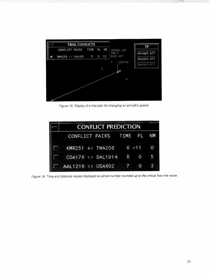
Figure 18. Display of a trial plan for changing an aircraft's speed.
Figure 19. Time and distance values displayed as whole number rounded up to the critical five mile value.
23


i i i iii ii ii
I Form ApprovedREPORT DOCUMENTATION PAGE ozo4-o eei i i
Public reporting burden for this collection of information is estimated to average 1 hour per response, including the time for reviewing instructions, searching existing data sources,gathering and maintaining the data needed, and completing and reviewing the collection of information. Send comments regarding this burden estimate or any other aspect of thiscollection of information, including suggestions for reducing this burden, to Washington Headquarters Services, Directorate for information Operations and Reports, 1215 JeffersonDavis Highway, Suite 1204, Arlington, VA 22202-4302, and to the Office of Management and Budget, Paperwork Reduction Project (0704-0188), Washington, DC 20503.
i i
1 AGENCY USE ONLY (Leave blank) ! 2. REPORT DATE
! April 19984. TITLE AND SUBTITLE
An Evaluation and Redesign of the Conflict Prediction and
Trial Planning Planview Graphical User Interface
6. AUTHOR(S)
Irene V. Laudeman, Connie L. Brasil,* and Philippe Stassarff
ORGA'NIZATIO ' '7. PERFORMING N NAME(S) AND ADDRESS(ES)
Ames Research Center
Moffett Field, CA 94035-1000
9. SPONSORING/MONITORING AGENCY NAME(S) AND ADDRE_;S(ES)
National Aeronautics and Space Administration
Washington, DC 20546-0001
ii
11. SUPPLEMENTARY NOTES
Point of Contact: Irene V. Laudeman, Ames Research Center, MS 262-5, Moffett Field, CA 94035-1000
(650) 604-0018
*San Jose State University,, San Jose, California.12a. DISTRIBUTION/AVAILABILITY STATEMENT
Unclassified _ Unlimited
Subject Category 03
3. REPORT TYPE AND DATES COVERED
Technical Memorandumi
5. FUNDING NUMBERS
538-18-22
8. PERFORMING ORGANIZATIONREPORT NUMBER
A-98-10366A
10. SPONSOhlI_G/MONITORING
AGENCY REPORT NUMBER
NASA/TM_1998-112227
i
*Sterlin_ Software, Redwood Shores, California.12b. DISTRIBUTI'ON CODE
i
13. ABSTRACT (Maximum 200 words)
The Planview Graphical User Interface (PGUI) is the primary display of air traffic for the Conflict
Prediction and Trial Planning function of the Center TRACON Automation System. The PGUI displays air
traffic information that assists the user in making decisions related to conflict detection, conflict resolution,
and traffic flow management. The intent of this document is to outline the human factors issues related to the
design of the conflict prediction and trial planning portions of the PGUI, document all human factors related
design changes made to the PGUI from December 1996 to September 1997, and outline future plans for the
ongoing PGUI design.
14. SUBJECT TERMS
Traffic management, Air traffic control displays, Conflict prediction
'17. SECURITY CLASSIFICATION
OF REPORT
Unclassified
NSN 7540-01-280-5500
18. SECURITY CLASSIFICATION
OF THIS PAGE
Unclassified
19. SECURITY CLAS'SIFICATION_----
OF ABSTRACT
i
15. NUMBER OF PAGES
2].16. PRICE CODE
A0320. LIMITATION OF ABSTRAC'F
Standard Form 298 (Rev. 2-89)Prescribed by ANSI Std. Z39-18
298-102