An Eulerian Approach to the Large Displacement Analysis of ...
50
1 An Eulerian Approach to the Large Displacement Analysis of Thin-Walled Frames B.A. Izzuddin * 1. ABSTRACT This paper presents a new approach for the geometrically nonlinear analysis of thin-walled space frames. The proposed approach employs an Eulerian (convected) system for the definition of local element freedoms, and is capable of representing the effects of large displacements, finite rotations and cross-sectional warping. The use of the Eulerian system has been shown to be advantageous in the context of adaptive elasto-plastic analysis, and the particular approach adopted has demonstrated a high level of accuracy which is quite insensitive to the size of the incremental load step. An important feature of the new approach is the separation of the transformations concerned with the effects of large displacements and finite rotations from the details of the element formulation, which allows the proposed approach to accommodate formulations of various degrees of sophistication. To demonstrate the accuracy of the new approach, a simple, yet powerful, finite element formulation is presented, which is capable of modelling thin-walled members with any open cross-sectional shape. Whilst such formulation is linear in the local system, its incorporation within the large displacement Eulerian approach allows geometrically nonlinear effects, such as lateral torsional buckling, to be accurately modelled. The incorporation of the local element response within a global nonlinear analysis capability based on the Eulerian approach is discussed, and essential requirements related to the coupling of warping freedoms of adjacent elements are outlined. Verification examples using ADAPTIC are finally presented to demonstrate the accuracy and efficiency of the proposed approach. * Lecturer in Engineering Computing, Civil Engineering Department, Imperial College, London SW7 2BU, U.K.
Transcript of An Eulerian Approach to the Large Displacement Analysis of ...

1
An Eulerian Approach to the
Large Displacement Analysis of Thin-Walled Frames
B.A. Izzuddin*
1. ABSTRACT
This paper presents a new approach for the geometrically nonlinear analysis of thin-walled space
frames. The proposed approach employs an Eulerian (convected) system for the definition of local
element freedoms, and is capable of representing the effects of large displacements, finite rotations
and cross-sectional warping. The use of the Eulerian system has been shown to be advantageous in
the context of adaptive elasto-plastic analysis, and the particular approach adopted has
demonstrated a high level of accuracy which is quite insensitive to the size of the incremental load
step. An important feature of the new approach is the separation of the transformations concerned
with the effects of large displacements and finite rotations from the details of the element
formulation, which allows the proposed approach to accommodate formulations of various degrees
of sophistication. To demonstrate the accuracy of the new approach, a simple, yet powerful, finite
element formulation is presented, which is capable of modelling thin-walled members with any
open cross-sectional shape. Whilst such formulation is linear in the local system, its incorporation
within the large displacement Eulerian approach allows geometrically nonlinear effects, such as
lateral torsional buckling, to be accurately modelled. The incorporation of the local element
response within a global nonlinear analysis capability based on the Eulerian approach is
discussed, and essential requirements related to the coupling of warping freedoms of adjacent
elements are outlined. Verification examples using ADAPTIC are finally presented to demonstrate
the accuracy and efficiency of the proposed approach.
* Lecturer in Engineering Computing, Civil Engineering Department, Imperial College, London SW7 2BU, U.K.

2
2. INTRODUCTION
The prediction of nonlinear structural response is increasingly finding application in design practice,
becoming less restricted to research activities. The design of important structures subject to severe
loading conditions is just one example where nonlinear analysis tools are proving indispensable,
allowing the complex interaction between structural components to be modelled in the range of
nonlinear response, which may be due to material inelasticity or geometric effects.
Thin-walled frames represent an important class of structures which cannot be accurately modelled
by conventional nonlinear frame analysis tools. This is mainly due to the inability of the underlying
methods to account for non-uniform cross-sectional warping, which significantly influences the
overall response of such structures, particularly with regard to lateral torsional instability. Whilst
advanced shell finite elements can provide an accurate prediction of the nonlinear response of thin-
walled members, their two-dimensional nature demands significant modelling and computational
efforts. Therefore, the use of this type of elements has been restricted to studying the nonlinear
response of individual members, or at best small assemblages, usually as part of parametric research
studies.
Over the recent decades, considerable research efforts have been devoted to extending the
capabilities of conventional nonlinear frame analysis methods, utilising one-dimensional finite
elements, to the domain of thin-walled structures1-9. These have been mainly driven by the
computational savings and modelling advantages to be derived, since a significant number of two-
dimensional shell elements could thus be replaced with few one-dimensional elements defined along
the member length. In these developments, the key issue has been the integration of the modelling of
cross-sectional warping within the nonlinear frame analysis procedures. Whilst earlier research work
has been mostly concerned with individual members1,4,5, the interaction of thin-walled members
within a structural frame has received significant attention, invariably using the Updated Lagrangian
approach. In particular, Conci and Gattass8 and Chen and Blandford9 employed such an approach
with a cantilever-bound local reference system10 to develop one-dimensional nonlinear finite
elements for thin-walled I-beams and members with any open cross-section, respectively.

3
The present work is concerned with extending an Eulerian approach, previously proposed by the
writer11,12 for the large displacement analysis of space frames, to the domain of thin-walled
structures. The main advantages of the new approach are its high level of accuracy which is quite
insensitive to the size of the incremental load step; its ability to readily accommodate elements of
various degrees of sophistication; and its natural applicability to adaptive elasto-plastic analysis13,14.
The latter consideration is particularly important, since adaptive analysis techniques have been
shown to provide significant modelling advantages and often more than 80% of computational
savings14.
The paper proceeds with outlining the fundamentals of the proposed Eulerian approach, and
describing the procedure for incorporating warping effects in the context of large displacement
analysis. Distinction is made between the transformation details required for large displacement
analysis and the details of element formulation, thus allowing the proposed approach to readily
accommodate various types of formulation. To illustrate the advantages of the Eulerian approach, a
simple, yet powerful, Eulerian formulation is described, which is capable of modelling thin-walled
members with any open cross-section. Verification and application examples, using the nonlinear
analysis program ADAPTIC15, are finally presented to demonstrate the accuracy and efficiency of
the proposed approach. Particular consideration is given to the nonlinear response of thin-walled
frames subject to lateral torsional instability, and comparisons are made where possible with the
results of other theoretical and numerical approaches.
3. BACKGROUND
Nonlinear structural analysis is mainly concerned with establishing the structural deformed shape,
hence strains and stresses, under equilibrium conditions and at various loading levels. In the context
of finite element analysis, the displacements U corresponding to a finite set of freedoms are obtained
by solving a nonlinear system of equilibrium equations, given by:
P j g
ef j
e for j 1,n (1)
where,

4
P j : global applied/equivalent load at freedom (j),
gef j : global resistance force of element (e) corresponding to freedom (j), and
n : total number of global freedoms.
For thin-walled frames, the displacements vector U includes translational, rotational as well as
warping freedoms. The applied load P can include forces as well as moments, although the nature of
global moments depends on the adopted definition for rotational freedoms12. It can also be shown
that the global element forces vector gef represents the first derivatives of the element strain energy
eU with respect to global displacements12, as given by:
gef j
(eU)
Uj
(2)
The formulation of the element strain energy eU in terms of the global displacements U becomes too
complex in the context of large displacement analysis, and hence a local system is often introduced.
Such a system utilises a set of local element freedoms cu , which can be used to define the element
strain energy, allowing the global element forces in (2) to be expressed as:
gef j
cu i
Uj
(eU)
c u i
i (3.a)
or,
gef j Tj,i cf i
i (3.b)
where,
T : transformation matrix between the local and global systems, and
cf i : local element force corresponding to local freedom (i).
Equation (3.b) depicts the separation of the large displacement transformations, represented by T,
from the details of the element response in the local system, represented by cf , which allows the
large displacement approach to be utilised with elements of various degrees of accuracy and
5
sophistication. The next section outlines the Eulerian approach proposed for the large displacement
analysis of thin-walled frames, presenting the relationship between local displacements cu and global
displacements U, thereby allowing the determination of the transformation matrix T. The proceeding
section describes a formulation for thin-walled members which is capable of modelling any open
cross-sectional shape, utilising the Eulerian system for deriving the local element forces cf .
Although the proposed formulation is linear in the local system, its incorporation within the large
displacement Eulerian approach allows geometrically nonlinear effects, such as lateral torsional
instability, to be accurately modelled.
4. EULERIAN SYSTEM
The Eulerian system is a local convected system which follows the element chord during
deformation, as shown in Fig. 1. This effectively isolates strain-inducing deformation states from
stress-free rigid body states, which proves to be quite convenient in formulating the details of the
local element response, as demonstrated in the following section.
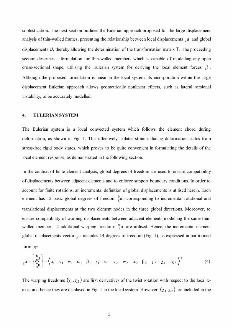
In the context of finite element analysis, global degrees of freedom are used to ensure compatibility
of displacements between adjacent elements and to enforce support boundary conditions. In order to
account for finite rotations, an incremental definition of global displacements is utilised herein. Each
element has 12 basic global degrees of freedom gbu , corresponding to incremental rotational and
translational displacements at the two element nodes in the three global directions. Moreover, to
ensure compatibility of warping displacements between adjacent elements modelling the same thin-
walled member, 2 additional warping freedoms gw
u are utilised. Hence, the incremental element
global displacements vector g
u includes 14 degrees of freedom (Fig. 1), as expressed in partitioned
form by:
gu gbu
gwu
u1 v1 w1 1 1 1 u2 v2 w2 2 2 2 1 2
T (4)
The warping freedoms 1, 2 are first derivatives of the twist rotation with respect to the local x-
axis, and hence they are displayed in Fig. 1 in the local system. However, 1, 2 are included in the

6
global displacements vector g
u since they are directly used to enforce cross-sectional warping
compatibility between adjacent elements, as discussed in more detail later.
In the local Eulerian system, an element utilises 8 degrees of freedom cu , as shown in Fig. 2, which
are expressed in total, rather than incremental, form. These include the 6 basic degrees of freedom
cbu and 2 additional warping freedoms c
wu , as given in partitioned form by:
cu c
bu
cwu
1y 1z 2y 2z T 1 2
T (5)
For a given set of global element displacements g
u , the increment of local basic displacements cbu
is determined from gbu as proposed previously by the writer11,12, which accounts for large
displacements and finite rotations. The increment of local warping displacement cw
u , representing
the remaining part of the incremental local displacements cu , is identical to gw
u , as expressed by:
c
wu g
wu (6)
Once cu has been determined for a given g
u , the total local displacements cu are established
incrementally from the previous equilibrium step:
cu c
bu
cw
u
(7.a)
cu cuo cu (7.b)
where,
cuo : local element displacements at the end of the last equilibrium step.
The local element response is thereafter obtained for the current local displacements cu , as
discussed in the following section.
7
5. ELEMENT RESPONSE
In the context of the proposed Eulerian approach, the accuracy and applicability of formulations
depends primarily on the details of the element response in the local system. Several formulations,
differing in applicability and complexity, have been proposed by the writer for large displacement
analysis of thin-walled frames; notably, a linear elastic formulation for members having an I-
section16, a nonlinear elastic formulation for representing a whole member using only one element17,
and an elasto-plastic formulation employing a yield criterion based on direct strains18.
The previous elastic formulation16 is extended herein to model thin-walled members with any open
cross-section, as discussed hereafter. Although such a formulation is linear in the local system, its
incorporation within the large displacement Eulerian approach allows geometric nonlinearity effects,
including lateral torsional instability, to be accurately modelled, as shown in the examples section of
this paper.
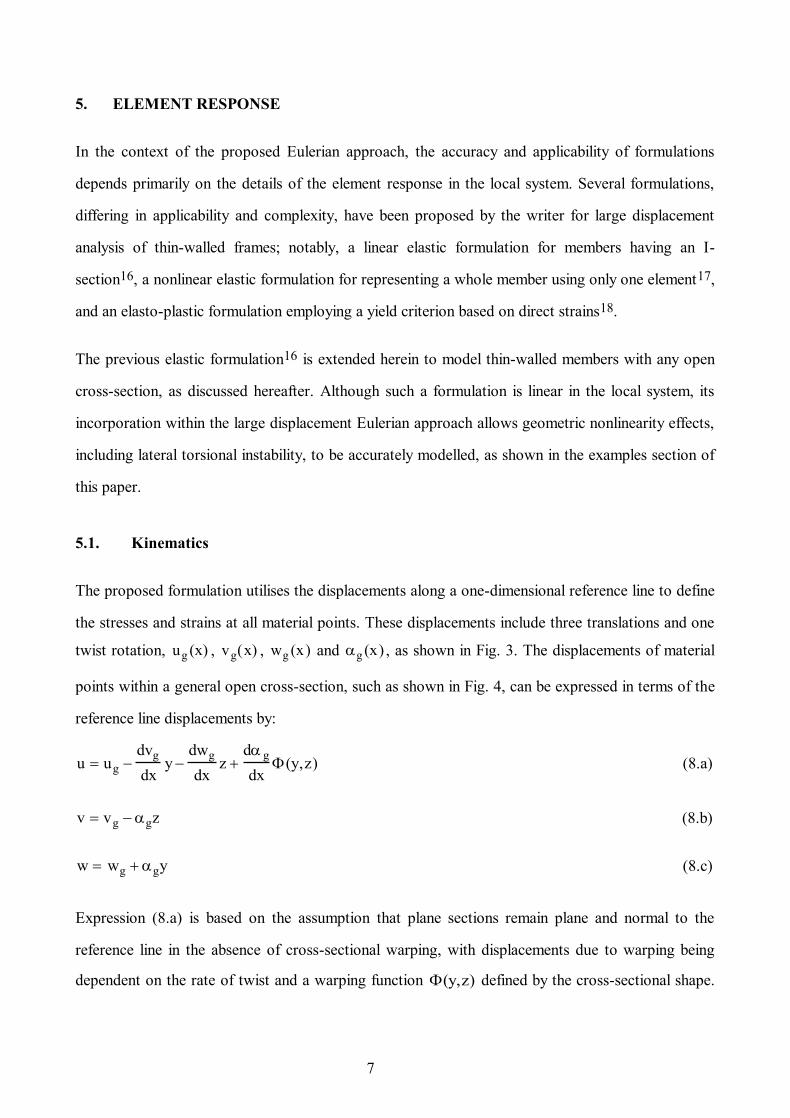
5.1. Kinematics
The proposed formulation utilises the displacements along a one-dimensional reference line to define
the stresses and strains at all material points. These displacements include three translations and one
twist rotation, ug (x) , vg(x) , wg (x) and g (x) , as shown in Fig. 3. The displacements of material
points within a general open cross-section, such as shown in Fig. 4, can be expressed in terms of the
reference line displacements by:
u ug dvg
dxy
dwg
dxz
dg
dx(y,z) (8.a)
v vg gz (8.b)
w wg gy (8.c)
Expression (8.a) is based on the assumption that plane sections remain plane and normal to the
reference line in the absence of cross-sectional warping, with displacements due to warping being
dependent on the rate of twist and a warping function (y,z) defined by the cross-sectional shape.
8
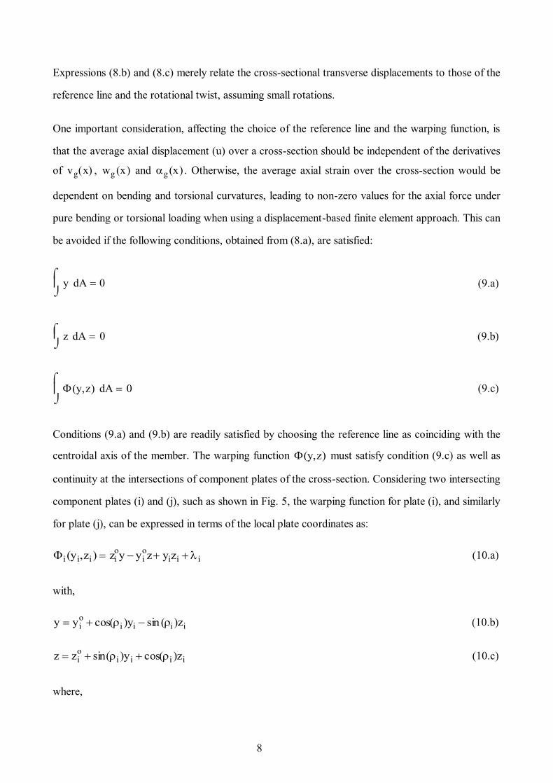
Expressions (8.b) and (8.c) merely relate the cross-sectional transverse displacements to those of the
reference line and the rotational twist, assuming small rotations.
One important consideration, affecting the choice of the reference line and the warping function, is
that the average axial displacement (u) over a cross-section should be independent of the derivatives
of vg(x) , wg (x) and g (x) . Otherwise, the average axial strain over the cross-section would be
dependent on bending and torsional curvatures, leading to non-zero values for the axial force under
pure bending or torsional loading when using a displacement-based finite element approach. This can
be avoided if the following conditions, obtained from (8.a), are satisfied:
y dA
0 (9.a)
z dA
0 (9.b)
(y,z) dA
0 (9.c)
Conditions (9.a) and (9.b) are readily satisfied by choosing the reference line as coinciding with the
centroidal axis of the member. The warping function (y,z) must satisfy condition (9.c) as well as
continuity at the intersections of component plates of the cross-section. Considering two intersecting
component plates (i) and (j), such as shown in Fig. 5, the warping function for plate (i), and similarly
for plate (j), can be expressed in terms of the local plate coordinates as:
i (yi,zi ) zioy yi
oz yizi i (10.a)
with,
y yio cos(i )yi sin (i )zi (10.b)
z zio sin(i )yi cos(i )zi (10.c)
where,

9
i : warping constant for plate (i).
The above expression for the warping function is derived from the condition that the out-of-plane
shear strain in any component plate as well as the in-plane shear strain at the plate mid-thickness are
zero. The warping constants i , required for completely defining the warping function, are obtained
from equations enforcing the continuity requirement at the intersection of two plates. Considering
again plates (i) and (j) in Fig. 5, this requirement is satisfied at the mid-thickness intersection of the
two plates if:
i
bi
2,0
j
b j
2,0
(11)
or using (10),
i j b i
2sin(i )y i
o cos(i )zi
o
b j
2sin(j )y j
o cos(j )zj
o
(12)
For a cross-section composed of (n) plates, (n-1) equations can be obtained using (12). One more
equation is needed to evaluate all the warping constants, which is directly determined from the
requirement (9.c) of a zero average for the cross-sectional warping displacements. Combining (9.c)
and (10.a), the required equation is obtained as:
bi ti ii1
n
0 (13)
The solution of the previous equations for the warping constants is simplified by establishing
i, i 2, n in terms of 1 using (12), and then substituting in (13) to determine 1 and,
consequently, all the other constants.
Having determined the warping function, the displacements over a cross-section, given by (8), can
be established once the reference line displacements, ug (x) , vg(x) , wg (x) and g (x) , are known.
Shape functions are used to interpolate these displacements in terms of the local element freedoms
cu shown in Fig. 2, in accordance with the displacement-based finite element approach. It is evident
from the element boundary conditions that a linear shape function can be used for ug (x) , whereas
cubic shape functions can be used for vg(x) and wg (x). Noting that cross-sectional warping is
10
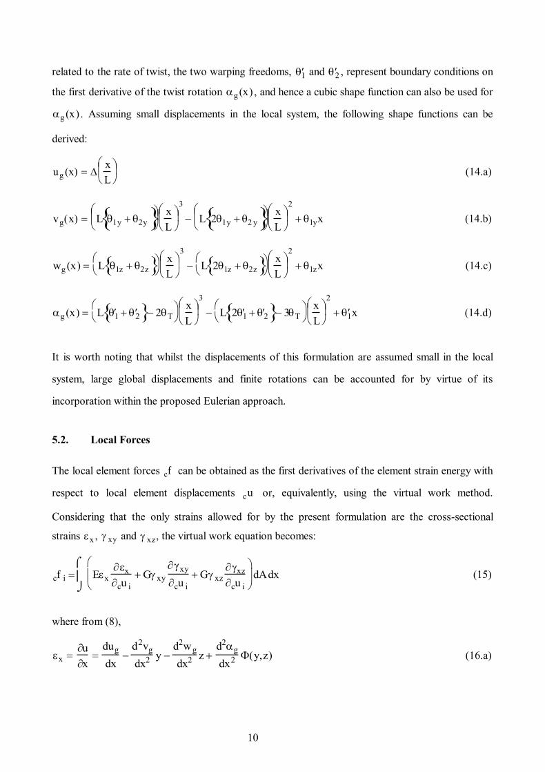
related to the rate of twist, the two warping freedoms, 1 and 2 , represent boundary conditions on
the first derivative of the twist rotation g (x) , and hence a cubic shape function can also be used for
g (x) . Assuming small displacements in the local system, the following shape functions can be
derived:
ug (x) x
L
(14.a)
vg(x) L 1y 2y
x
L
3
L 21y 2 y
x
L
2
1yx (14.b)
wg (x) L 1z 2z
x
L
3
L 21z 2z
x
L
2
1zx (14.c)
g (x) L 1 2 2T
x
L
3
L 2 1 2 3T
x
L
2
1x (14.d)
It is worth noting that whilst the displacements of this formulation are assumed small in the local
system, large global displacements and finite rotations can be accounted for by virtue of its
incorporation within the proposed Eulerian approach.
5.2. Local Forces
The local element forces cf can be obtained as the first derivatives of the element strain energy with
respect to local element displacements cu or, equivalently, using the virtual work method.
Considering that the only strains allowed for by the present formulation are the cross-sectional
strains x , xy and xz, the virtual work equation becomes:
cf i Ex
x
cu i
G xy
xy
cu i
G xz
xz
cu i
dAdx
(15)
where from (8),
x u
x
dug
dx
d2vg
dx2 y d2wg
dx2 z d2g
dx2 (y,z) (16.a)
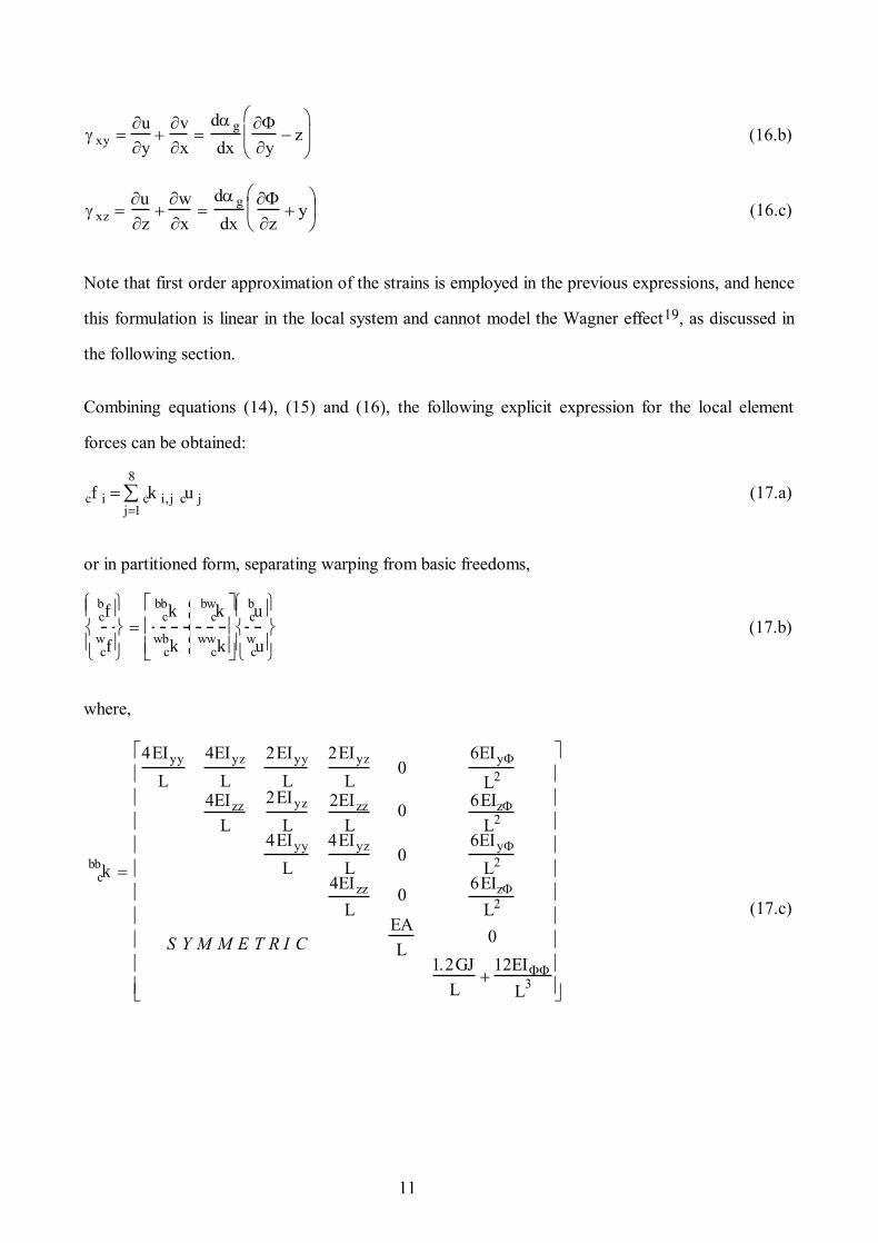
11
xy u
yv
x
d g
dx
y z
(16.b)
xz u
zw
x
dg
dx
z y
(16.c)
Note that first order approximation of the strains is employed in the previous expressions, and hence
this formulation is linear in the local system and cannot model the Wagner effect19, as discussed in
the following section.
Combining equations (14), (15) and (16), the following explicit expression for the local element
forces can be obtained:
cf i ck i,j cu j
j1
8
(17.a)
or in partitioned form, separating warping from basic freedoms,
cbf
cw
f
cbb
k cbw
k
cwb
k cww
k
cbu
cw
u
(17.b)
where,
cbb
k
4EIyy
L
4EIyz
L
2EIyy
L
2EIyz
L0
6EIy
L2
4EIzz
L
2EIyz
L
2EIzz
L0
6EIz
L2
4EIyy
L
4EIyz
L0
6EIy
L2
4EIzz
L0
6EIz
L2
EA
L0
1.2GJ
L
12EI
L3
S Y M M E T R I C
(17.c)

12
cbw
k cbw
kT
4EIy
L
2EIy
L4EIz
L
2EIz
L2EIy
L
4EIy
L2EIz
L
4EIz
L
0 0
0.1GJ 6EI
L20.1GJ
6EI
L2
(17.d)
cww
k
0.4GJL
3
4EI
L
0.1GJL
3
2EI
L0.4GJL
3
4EI
L
SYMMETRIC (17.e)
The cross-sectional constants used in the above expressions for the local stiffness matrix ck are
defined as follows:
A dA
(18.a)
Iyy y2
dA
(18.b)
Iyz yz dA
(18.c)
Iy ydA
(18.d)
Izz z2
dA
(18.e)
Iz z dA
(18.f)

13
I 2
dA
(18.g)
J 4zi2
dAii1
n
(18.h)
Explicit expressions for the above constants for a general thin-walled open cross-section are given in
Appendix A.1.
5.3. Warping Deformations
The choice of the centroidal axes as the reference line for the cubic element leads to considerable
simplification in the element formulation. However, centroidal formulations have distinctive
behavioural characteristics, particularly in relation to the warping of asymmetric open cross-sections.
Considering a channel section as an example asymmetric cross-section, the warping deformations for
a centroidal formulation can be verified using (10) to be distributed over the cross-section as shown
in Fig. 6.a. If, on the other hand, the origin of the warping freedom is taken outside the channel web,
for example at the shear centre, the warping deformations would be distributed as in Fig. 6.b.
However, such deformations can be represented by the centroidal cubic formulation, since they are a
combination of the warping deformations in Fig. 6.a with a cross-sectional rotation about the y-axis.
Hence, centroidal and shear centre formulations have in most situations equivalent response
characteristics, although they utilise different freedoms.
There are some differences between the two types of formulation, with shear centre formulations
having a disadvantage related to the connectivity of elements being enforced outside the asymmetric
cross-section domain. This could lead to spurious situations especially for elements meeting at an
angle.
Another important difference is related to warping releases in the presence of rotational restraints or
moments. Considering an element having a channel cross-section, with one of the element nodes
restrained against all displacements and rotations except for the warping freedom. Clearly, the only

14
cross-sectional deformations allowed by centroidal formulations are the warping deformations of
Fig. 6.a, while shear centre formulations would only allow the deformations shown in Fig. 6.b.
Although this leads to different response predictions by the two types of formulation, such a
situation is not believed to be realistic, since it would be difficult in practice to have a system of
forces which provides rotational restraints whilst not resisting the two aforementioned warping
modes.
6. GLOBAL ANALYSIS
The two main requirements for a nonlinear structural analysis capability are (i) the ability to establish
and assemble the global element resistance forces, i.e. the right-hand side of (1), given an increment
of global displacements U, and (ii) the formulation of a global tangent stiffness matrix which can be
used within an incremental iterative approach, such as the Newton-Raphson procedure. These are
discussed hereafter in the context of the proposed Eulerian approach for large displacement analysis
of thin-walled frames, highlighting a number of important considerations particularly in relation to
global warping freedoms.
6.1. Global Forces
The vector of incremental global element displacements g
u represents a subset of the incremental
structural displacements U, from which the local element displacements cu can be obtained in
accordance with Section 4. The local element forces cf corresponding to cu can be readily
established, as given explicitly in Section 5.2 for the elastic cubic formulation. To determine the
element contribution to global resistance forces gef , the following transformation is applied to cf :
gef j Tj,i cf i
i1
8
(19.a)
where applying (3) on the element level:
Tj,i cu i
gu j
(19.b)

15
The transformation matrix T can be expressed in partitioned form, separating the warping and basic
element freedoms, as follows:
T
bbT bw T
wbT ww T
(20.a)
where,
bbTj,i
cbu i
gb u j
(20.b)
bwTj,i
cw u i
gb u j
(20.c)
wbTj,i
cb u i
gw u j
(20.d)
wwTj,i
cwu i
gwu j
(20.e)
Matrix bb
T accounts for the effects of large displacements and finite rotations, and consists of 12x6
terms which have been previously derived by the writer in an explicit form11,12. According to
Section 4, bw
T and wb
T are 12x2 and 2x6 zero matrices, respectively, whereas ww
T is a 2x2
identity matrix:
wwT
1 0
0 1
(21)
The choice of the element type affects the calculation of the local forces cf corresponding to a set of
local displacements cu ; however, the details of the transformation matrix T and its application
according to (19.a) are unaffected, which allows the proposed Eulerian approach to accommodate
centroidal or shear centre formulations of various levels of accuracy, applicability and sophistication.
Although the elastic cubic formulation presented in the previous section is linear and assumes small
displacements in the local Eulerian system, the global element forces obtained from (19.a) are
nonlinear with respect to the global increment of displacements, since the effects of large nodal

16
displacements and rotations are accounted for. Geometric nonlinearity effects which can be
attributed to nodal displacements, such as lateral torsional instability, can be accurately represented
by this simple formulation if a sufficient number of elements is used within individual members.
However, geometric nonlinearities due to cross-sectional deformation, such as the Wagner effect19,
require a more involved formulation which is nonlinear in the local Eulerian system, such as the
nonlinear elastic quartic formulation proposed by the writer17.
6.2. Global Tangent Stiffness
The global element tangent stiffness matrix g
k , required for the nonlinear iterative solution
procedure, is defined as:
gk i, j
gf i
gu j
(22)
Combining (22) with (19), and applying chain differentiation rules, the following expression for g
k
can be obtained:
gk i, j Ti,k
cf k
gu j
Ti,k
gu jcf k
k1
8
Ti,k
cf k
cu m
cum
gu jm1
8
2cu k
gu i gu jcf k
k1
8
gk i,j Ti,k ck k,m Tm,jm1
8
sGi, j,k cf k
k1
8
(23.a)
in which,
ck k,m
cf k
cum
(23.b)
sGi,j,k
2cu k
gu i gu j
(23.c)
The local tangent stiffness matrix ck is dependent on the element type, and is given for the elastic
cubic formulation by (17). Array sG is a 14x14x8 geometric array governing the effect of the current
17
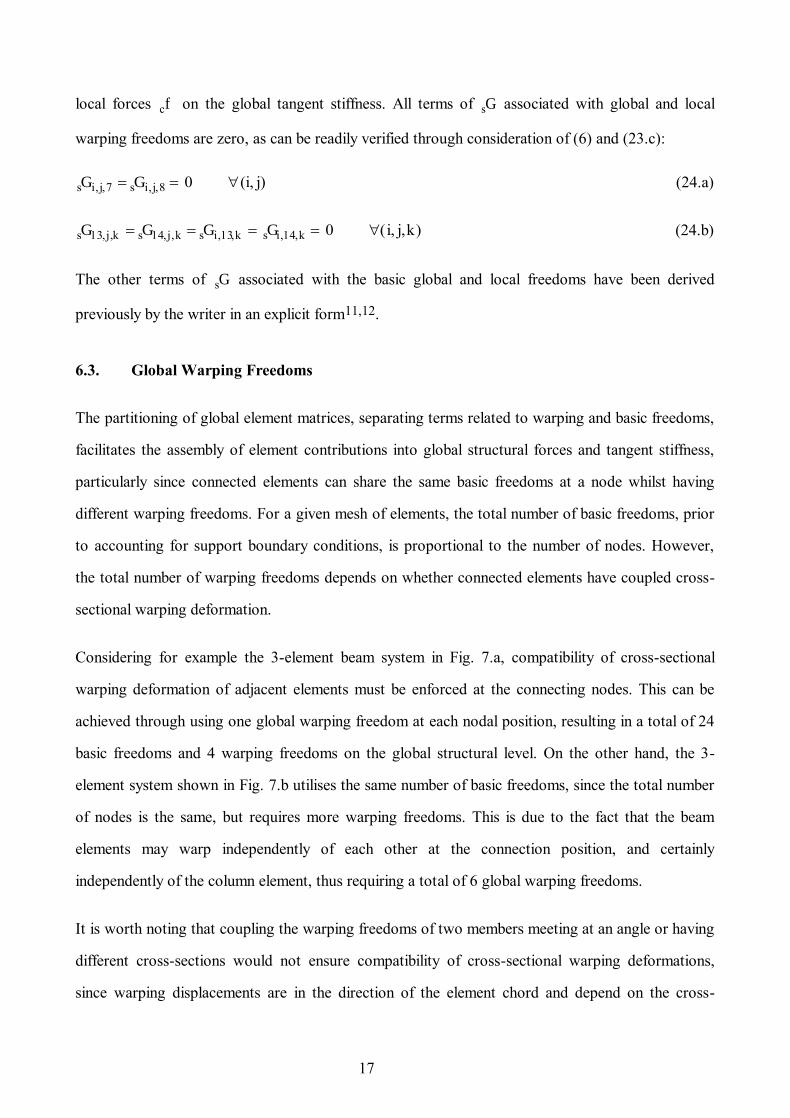
local forces cf on the global tangent stiffness. All terms of sG associated with global and local
warping freedoms are zero, as can be readily verified through consideration of (6) and (23.c):
sGi,j,7 sGi,j,8 0 (i, j) (24.a)
sG13,j,k sG14,j,k sGi,13,k sGi,14,k 0 (i, j,k) (24.b)
The other terms of sG associated with the basic global and local freedoms have been derived
previously by the writer in an explicit form11,12.
6.3. Global Warping Freedoms
The partitioning of global element matrices, separating terms related to warping and basic freedoms,
facilitates the assembly of element contributions into global structural forces and tangent stiffness,
particularly since connected elements can share the same basic freedoms at a node whilst having
different warping freedoms. For a given mesh of elements, the total number of basic freedoms, prior
to accounting for support boundary conditions, is proportional to the number of nodes. However,
the total number of warping freedoms depends on whether connected elements have coupled cross-
sectional warping deformation.
Considering for example the 3-element beam system in Fig. 7.a, compatibility of cross-sectional
warping deformation of adjacent elements must be enforced at the connecting nodes. This can be
achieved through using one global warping freedom at each nodal position, resulting in a total of 24
basic freedoms and 4 warping freedoms on the global structural level. On the other hand, the 3-
element system shown in Fig. 7.b utilises the same number of basic freedoms, since the total number
of nodes is the same, but requires more warping freedoms. This is due to the fact that the beam
elements may warp independently of each other at the connection position, and certainly
independently of the column element, thus requiring a total of 6 global warping freedoms.
It is worth noting that coupling the warping freedoms of two members meeting at an angle or having
different cross-sections would not ensure compatibility of cross-sectional warping deformations,
since warping displacements are in the direction of the element chord and depend on the cross-

18
sectional shape, respectively. Although such situations can be simplified by decoupling the warping
freedoms and associating free, fully-restrained or intermediate boundary conditions with these
freedoms, improved accuracy would be achieved if two-dimensional elements are used to model the
connection details. However, significant modelling and computational advantages could still be
attained through using one-dimensional elements in the other regions of the structure, with interface
elements employed to couple the displacements of one-dimensional and two-dimensional elements
within the hybrid mesh.
7. EXAMPLES
The proposed Eulerian approach and the cubic formulation have been implemented in the structural
analysis program ADAPTIC15 version v2.3.2, which is a general purpose program for the nonlinear
static and dynamic analysis of steel, reinforced concrete and composite frames. Four examples are
undertaken using ADAPTIC to demonstrate the accuracy and applicability of the Eulerian approach,
in general, and the cubic formulation, in particular.
7.1. I-Beam
A simply supported I-beam is restrained against twist at its two ends and is subjected to two equal
moments resulting in uniform bending along the beam, as shown in Fig. 8. The applied moments are
quasi-tangential20, simulated by means of rigid cross-links at the ends, although the nature of the
moments has no effects for this example due to the twist restraints.
For the case of free warping at the member ends, the theoretical lateral torsional buckling moment is
given by21:
M c1
L
EIzz
GJ EI
2
L2
,
whereas, for the case of full warping restraint at the member ends, the theoretical lateral torsional
buckling moment is given by22:

19
M c2
0.883L
EIzz
GJ EI
2
0.492L 2
,
in which
1Izz
Iyy
Chwalla's constant () accounts for the effect of pre-buckling vertical displacement on the buckling
load. Such an effect becomes significant if the second moment of area about the minor axis Izz is
significant in comparison with the second moment of area about the major axis Iyy .
The response of the I-beam with free warping at the ends has been studied using three mesh
configurations of cubic elements, namely, 2, 4 and 10 elements, where in all cases the symmetric I-
section as been modelled with 5 component plates. In order to initiate lateral torsional instability, a
quasi-tangential moment of 0.01Mc1 about the minor axis is initially applied at the right end of the
beam, after which the two moments about the major axis are increased proportionally up to and
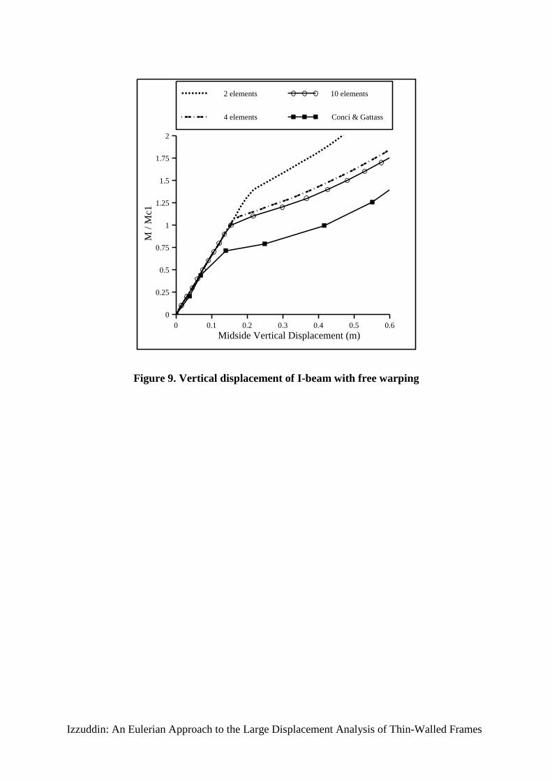
beyond the point of lateral torsional buckling. The results shown in Fig. 9 demonstrate excellent
agreement between the buckling moment prediction of the fine mesh of 10 elements and the
theoretical solution (M/Mc1 = 1). It is also evident that two cubic elements, while predicting lateral
torsional instability, overestimate the buckling moment by more than 25%. The comparison in Fig. 9
with the results of Conci and Gattass8, who used 8 elements based on the Natural Approach,
demonstrates the superior performance of the cubic formulation proposed herein. It would appear
that Conci and Gattass did not account for Chwalla's constant () in their comparisons with the
theoretical solution.
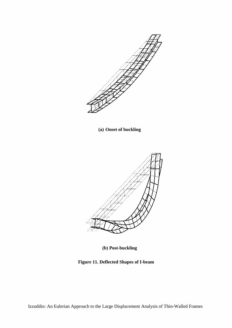
For the case of full warping restraint, the results in Fig. 10 demonstrate the accuracy of 10 cubic
elements and the reasonable prediction afforded by 4 cubic elements. Here as well, the superior
performance of the cubic formulation is illustrated, where the formulation of Conci and Gattass,
using 8 elements, underestimates the buckling load by more than 25%. Deflected shapes of the I-

20
beam obtained for the case of 10 cubic elements are shown to scale in Figs. 11.a and 11.b, which
depict the pre- and post-buckling deflections, respectively.
7.2. C-Beam
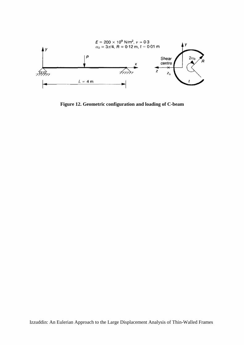
The thin-walled beam with a circular open cross-section, shown in Fig. 12, has the same support
conditions as the previous I-beam with free warping at the member ends, and is subjected to a
midspan vertical load applied in the close vicinity of the cross-section shear centre. The cross-section
is modelled using 12 straight plate segments, although the cross-sectional properties can be obtained
using an analytical expression of the warping function as in Appendix A.2. The beam is modelled
using two meshes of 4 and 10 cubic elements, respectively, with the load application at the shear
centre achieved by means of a rigid link to the centroidal line.
The C-beam buckles laterally at the theoretical buckling load given by21:
P c 16.94
L2
EIzz
GJ EI
2
L2
,
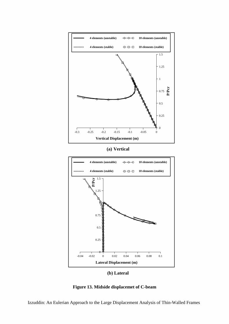
however, its post-buckling response is asymmetric, characterised by stable and unstable paths
depending on the relative position of the load with respect to the shear centre. The stable and
unstable post-buckling responses are initiated herein by varying the point of loading within a 0.6 mm
region around the shear centre, with the stable response obtained when the load is closer to the
centroid. Results for the vertical and lateral displacements as well as the midside twist, shown in
Figs. 13.a and 13.b, provide excellent agreement with the theoretical buckling load (P/Pcr = 1), and
demonstrate the high accuracy of a coarse mesh of 4 cubic elements. It is worth noting that the
buckling load is significantly influenced by the level of eccentricity from the shear centre in the
unstable case, with a potential reduction of over 40%. The post-buckling and final deflected shapes
for the mesh of 10 cubic elements are shown in Figs. 14.a and 14.b for the unstable case, and in
Figs. 15.a and 15.b for the stable case.

21
7.3. L-Frame
The L-frame in Fig. 16 consists of two members having a channel cross-section with the web lying in
the plane of the frame, and with warping restraints imposed at the built-in support and the corner
joint. The geometrically nonlinear response of this frame to a concentrated load applied at the shear
centre has been investigated by Chen and Blandford9 using 8 Updated Lagrangian elements
employing a shear centre formulation. For verification purposes, the proposed Eulerian cubic
formulation is also used to study this problem, with the element properties corresponding to those
given by Ref. [9] as indicated in Fig. 16.
Comparison of the results in Figs. 17.a and 17.b shows that 8 Eulerian cubic elements overestimate
the buckling load by 6%, but otherwise provide reasonable agreement with the results of Ref. [9]
considering the large displacements involved. The difference between the two sets of results is not a
shortcoming of the Eulerian approach, but is mainly attributed to the simplicity of the cubic
formulation which is linear in the local system, and hence cannot model the Wagner effect19. Such
an effect becomes important for members with an asymmetric cross-section subject to bending about
the axis of asymmetry, and for members which are subject to axial forces, the latter being the main
consideration for this problem. To illustrate this point, the same problem is analysed using another
Eulerian formulation17 which employs quartic shape functions for transverse displacements and
rotational twist, and which is capable of modelling the nonlinear Wagner effect in the local system.
As shown in Figs. 17.a and 17.b, the results using only 4 quartic elements provide excellent
agreement with the buckling load prediction of Ref. [9] using 8 elements, thus demonstrating the
accuracy of the proposed Eulerian approach. The difference in results at very large displacements
may be partly due to the quartic formulation requiring more cross-sectional properties than were
provided by Ref. [9].
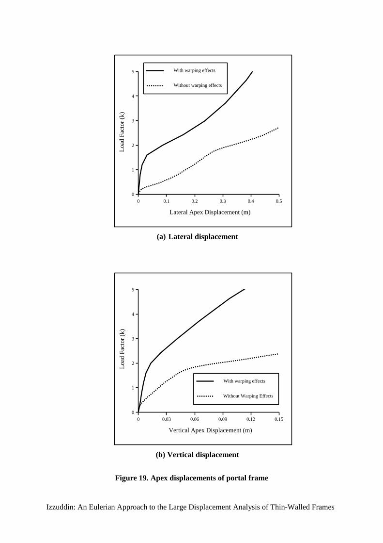
7.4. Portal Frame
The portal frame, depicted in Fig. 18, has an out-of-plane imperfection at its apex of 1 cm and is
assumed to have full warping restraints at the ends of all its members. The response of the portal
frame to the shown vertical loading is obtained using 1, 2 and 10 cubic elements per member.

22
The results shown in Figs. 19.a and 19.b illustrate the applicability of the cubic formulation to global
analysis of structures subject to lateral torsional instability and demonstrate the accuracy of the new
formulation, which is capable, even with 2 elements per member, of accurately predicting the
buckling and post-buckling response of the portal frame. The final deflected shape of the portal
frame is shown in Fig. 20.
In order to demonstrate the significance of non-uniform warping for this type of problem, the same
portal frame is analysed using Eulerian elements which do not account for warping effects. Each
frame member is modelled using two elements, which are identical to the proposed cubic formulation
except that they do not utilise warping freedoms and assume uniform warping along the element
length. Comparison of the results in Fig. 21 shows that neglecting the warping effects leads to over
80% reduction in the buckling load, and results in a considerable change in the frame response. This
is primarily attributed to the discontinuity in the cross-sectional warping deformation over adjacent
elements modelling the same member, as well as the inability to enforce warping restraints at the
member ends, as shown in Fig. 22.
8. CONCLUSIONS
This paper described a new approach for the large displacement analysis of thin-walled frames. The
proposed approach employs an Eulerian (convected) system for modelling large displacement effects
as well as geometric nonlinearities which can be associated with nodal displacements. Whilst the
Eulerian approach is formulated in such a way to allow the incorporation of various types of
formulation, its accuracy and applicability was demonstrated through the use of a simple cubic
formulation which was described in detail.
Verification examples using the nonlinear analysis program ADAPTIC showed the applicability of
the proposed procedures to the nonlinear analysis of thin-walled members with any open cross-
section, and more generally to the analysis of thin-walled frames. The cubic formulation provided
excellent prediction of lateral torsional instability effects for members subject to bending about a
cross-sectional axis of symmetry, but otherwise, and in the presence of significant axial forces, its

23
accuracy diminished since it does not account for the Wagner effect. This was shown to be a
shortcoming of the cubic formulation and not the Eulerian approach, which, by virtue of its ability to
accommodate more advanced formulations, was proven to model such effects to a high level of
accuracy.
The computational and modelling advantages of one-dimensional nonlinear formulations for thin-
walled members are significant, especially considering that a frame which can be modelled using few
one-dimensional elements would require hundreds of computationally expensive two-dimensional
shell elements. In the context of one-dimensional formulations, the Eulerian approach has been
shown in previous work to have considerable computational advantages and provide a convenient
framework for adaptive elasto-plastic analysis. This has formed the impetus for extending the
Eulerian approach to the domain of thin-walled frames, with the next natural step being the
development of adaptive analysis techniques for this type of structures. It is not suggested, however,
that one-dimensional nonlinear elements would eventually replace two-dimensional shell elements in
the analysis of thin-walled frames, since there are complex effects, such as those related to member
connections, which are quite difficult to model with one-dimensional elements. It is proposed,
nevertheless, that hybrid meshes should be adopted, with one dimensional elements used where
applicable to provide modelling and computational efficiency, and two-dimensional elements
employed where needed to improve accuracy. Clearly, this would call for the development of
nonlinear interface elements which are capable of enforcing continuity requirements between the
different element types within the same mesh.
9. REFERENCES
1. Trahair N.S. Restrained Elastic Beam-Columns. Journal of the Structural Division, ASCE,
1969, 95, ST12, pp. 2641-2664.
2. Barsoum R.S. and Gallagher R.H. Finite Element Analysis of Torsional and Torsional-Flexural
Stability Problems. International Journal for Numerical Methods in Engineering, 1970, 2, pp.
335-352.

24
3. Bazant Z.P. and El-Nimeiri M. Large-Deflection Spatial Buckling of Thin-Walled Beams and
Frames. Journal of the Engineering Mechanics Division, ASCE, 1973, 99, EM6, pp. 1259-
1281.
4. Epstein M. and Murray D.W. Three-Dimensional Large Deformation Analysis of Thin-Walled
Beams. International Journal of Solids and Structures, 1976, 12, pp. 867-876.
5. Sekulovic M. Geometrically nonlinear analysis of thin-walled members. M.N. Pavlovic (ed.),
Steel Structures: recent research advances and their application to design, 1986, Elsevier
Applied Science Publishers, London, p.219-243.
6. Yang Y.B. and McGuire W. Stiffness Matrix for Geometric Nonlinear Analysis. Journal of
Structural Engineering, ASCE, 1986, 112, No. 4, pp. 853-877.
7. Chan S.L. and Kitipornchai S. Geometric Nonlinear Analysis of Asymmetric Thin-Walled
Beam-Columns. Engineering Structures, 1987, 9, pp. 243-254.
8. Conci A. and Gattass M. Natural Coordinates for Geometric Nonlinear Analysis of Thin-Walled
Frames. International Journal for Numerical Methods in Engineering, 1990, 30, pp. 207-231.
9. Chen H. and Blandford G.E. Thin-Walled Space Frames. Parts I & 2. Journal of Structural
Engineering, ASCE, 1991, 117, No. 8, pp. 2499-2539.
10. Elias Z.M. Theory and Methods of Structural Analysis. John Wiley and Sons, New York, 1985.
11. Izzuddin B.A. Nonlinear Dynamic Analysis of Space Frames. Thesis Submitted for the Degree
of Doctor of Philosophy in the University of London, Department of Civil Engineering, Imperial
College, London, 1991.
12. Izzuddin B.A. and Elnashai A.S. Eulerian Formulation for Large Displacement Analysis of
Space Frames. Journal of Engineering Mechanics, ASCE, 1993, 119, No. 3, pp. 549-569.

25
13. Izzuddin B.A. and Elnashai A.S. Adaptive Space Frame Analysis. Part I: A Plastic Hinge
Approach. Proceedings of the Institution of Civil Engineers, Structures and Buildings, 1993,
99, August, pp. 303-316.
14. Izzuddin B.A. and Elnashai A.S. Adaptive Space Frame Analysis. Part II: A Distributed
Plasticity Approach. Proceedings of the Institution of Civil Engineers, Structures and
Buildings, 1993, 99, August, pp. 317-326.
15. Izzuddin B.A. and Elnashai A.S. ADAPTIC: A Program for the Adaptive Dynamic Analysis of
Space Frames, User Manual, 1989, Imperial College, London.
16. Izzuddin B.A. and Lloyd Smith D. A Cubic Eulerian Formulation for Elastic Warping
Structures. CIVIL-COMP'93 Conference Proceedings, 1993, The Fifth International
Conference on Civil & Structural Engineering Computing, Edinburgh.
17. Izzuddin B.A. Nonlinear Analysis of Frames Subject to Lateral Torsional Instability. In
Structural Dynamics, eds. Moan T. et al, 1993, A.A. Balkema, Rotterdam, pp. 603-608.
18. Izzuddin B.A. and Lloyd Smith D. An Elasto-Plastic Formulation for Thin-Walled Structures.
CST'94 Conference Proceedings, 1994, The Second International Conference on
Computational Structures Technology, Athens.
19. Goto Y. and Chen W.F. On the Validity of Wagner Hypothesis. International Journal of Solids
& Structures, 1989, 25, No. 6, pp. 621-634.
20. Argyris J.H., Dunne P.C. and Scharpf D.W. On Large Displacement Small Strain Analysis of
Structures with Rotational Degrees of Freedom. Computer Methods in Applied Mechanics and
Engineering, 1978, (14, pp. 401-451) continued on (15, pp. 99-135).
21. Allen H.G. and Bulson P.S. Background to Buckling. McGraw Hill, Maidenhead, Berkshire,
U.K., 1980.
22. Chajes A. Principles of structural stability theory. Prentice-Hall, Englewood Cliffs, N.J., 1974.

26
APPENDIX A
A.1. Properties of General Thin-Walled Cross-Section
For a general thin-walled cross-section composed on (n) plates, the stiffness constants can be
expressed in a summation form over the individual plates, as follows:
A bi tii1
n
(25.a)
Iyy b i ti
12ci b i
2 si ti
212y i
o2
i1
n
(25.b)
Iyz bi ti
12ci si bi
2 t i2 12y i
ozi
o
i1
n
(25.c)
Iy bi ti
1212 i yi
o ci si yi
ob i
2 t i2 zi
oci b i
2 si ti
2
i1
n
(25.d)
Izz b i ti
12si b i
2 ci ti
212zi
o2
i1
n
(25.e)
Iz b i ti
1212i zi
o ci si zi
ob i
2 ti2 yi
osi bi
2 ci ti
2
i1
n
(25.f)
I b i ti
1212 i
2 ti2 ci y i
o si zi
o
2
bi3 ti
144ti
2 12 si yio ci zi
o
2
i1
n
(25.g)
J bi ti
3
3i1
n
(25.h)
in which,
ci cos(i ) (26.a)
si sin(i ) (26.b)
and,

27
n : number of component plates
i : warping constant of plate (i) determined from (12)-(13).
All other variables are geometric properties of plate (i), as shown in Fig. 5.
A.2. Properties of Open Circular Cross-Section
With reference to Fig. 12, and assuming small thickness in comparison with the section radius
(t<<R), the following cross-sectional properties can be derived:
A 2Rto (27.a)
Iyy R3t
22o sin (2o ) (27.b)
Izz R3t
2o
2 2o2 2cos(2o ) o sin (2o ) (27.c)
Iy R4t sin(o ) 1
sin (2o )
2o
2o cos(2o )
(27.d)
I R5t
2o3
3
3sin 2(o )
o
sin(2o ) 2 sin2 (o )
2o2
(27.e)
Iyz Iz 0 (27.f)
J 2Rot3
3 (27.g)
It can be also shown for any cross-section that the position of the shear centre with respect to the
centroid is given by:
y s Iz
Izz
(28.a)
zs Iy
Iyy
(28.b)
28
NOTATION
- Generic symbols of matrices and vectors are represented by bold font-type with left side
subscripts or superscripts (e.g. sG, gef ). This rule also applies to three-dimensional matrices.
- Subscripts and superscripts to the right side of the generic symbol indicate the term of the vector
or matrix under consideration (e.g. sGi, j,k ,
gef j ).
Operators
o : right-side superscript, denotes initial values during an incremental step.
: right-side superscript, transpose sign.
: incremental operator for variables, vectors and matrices.
: partial differentiation.
i
: summation over range variable (i).
: encloses terms of a matrix.
: encloses terms of a row vector.
Symbols
A : cross-sectional area
bi : width of component plate (i)
E : elastic Young's modulus
cf : local element forces
gef : global forces of element (e)
29
G : shear modulus
sG : geometric stiffness matrix
I#* : cross-sectional properties defined in (18)
J : St. Venant's torsional constant
ck : local element tangent stiffness matrix
gk : global element tangent stiffness matrix
L : element length
n : number of component plates within a cross-section
P : global applied forces
t i : thickness of component plate (i)
T : transformation matrix from local to global forces
u : cross-sectional displacement in local x-direction
u g : reference line displacement in local x-direction
cu : local element displacements, including cbu and c
wu
1y 1z 2y 2z T 1 2
T
gu : global element displacements, including
gbu and
gw
u
u1 v1 w1 1 1 1 u2 v2 w2 2 2 2 1 2
T
U : global structural displacements
eU : strain energy of element (e)

30
v : cross-sectional displacement in local y-direction
v g : reference line displacement in local y-direction
w : cross-sectional displacement in local z-direction
wg : reference line displacement in local z-direction
y i, zi : local coordinates for component plate (i)
yio,zi
o : origin of component plate (i)
g : reference line twist rotation
x : direct strain
(y,z) : warping function of cross-section
: Chwalla's constant
xy, xz : shear strains
i : warping constant for component plate (i)
i : angle of component plate (i)

Izzuddin: An Eulerian Approach to the Large Displacement Analysis of Thin-Walled Frames
Figure 1. Eulerian (convected) system in relation to global reference system

Izzuddin: An Eulerian Approach to the Large Displacement Analysis of Thin-Walled Frames
Figure 2. Local Eulerian displacements

Izzuddin: An Eulerian Approach to the Large Displacement Analysis of Thin-Walled Frames
Figure 3. Reference line displacements in Eulerian system

Izzuddin: An Eulerian Approach to the Large Displacement Analysis of Thin-Walled Frames
Figure 4. General thin-walled open cross-section

Izzuddin: An Eulerian Approach to the Large Displacement Analysis of Thin-Walled Frames
Figure 5. Component plates in an open cross-section

Izzuddin: An Eulerian Approach to the Large Displacement Analysis of Thin-Walled Frames
Figure 6. Warping deformation of channel section:
a) about centroid; b) about shear centre

Izzuddin: An Eulerian Approach to the Large Displacement Analysis of Thin-Walled Frames
Figure 7. Global freedoms of thin-walled structural systems:
a) thin-walled beam; b) intersecting thin-walled members

Izzuddin: An Eulerian Approach to the Large Displacement Analysis of Thin-Walled Frames
Figure 8. I-beam subject to end moments
Izzuddin: An Eulerian Approach to the Large Displacement Analysis of Thin-Walled Frames
0
0.25
0.5
0.75
1
1.25
1.5
1.75
2
0 0.1 0.2 0.3 0.4 0.5 0.6
M /
Mc1
Midside Vertical Displacement (m)
2 elements
4 elements
10 elements
Conci & Gattass
Figure 9. Vertical displacement of I-beam with free warping

Izzuddin: An Eulerian Approach to the Large Displacement Analysis of Thin-Walled Frames
0
0.25
0.5
0.75
1
1.25
1.5
1.75
2
0 0.1 0.2 0.3 0.4 0.5 0.6 0.7
M /
Mc2
Midside Vertical Displacement (m)
2 elements
4 elements
10 elements
Conci & Gattass
Figure 10. Vertical displacement of I-beam with restrained warping
Izzuddin: An Eulerian Approach to the Large Displacement Analysis of Thin-Walled Frames
(a) Onset of buckling
(b) Post-buckling
Figure 11. Deflected Shapes of I-beam
Izzuddin: An Eulerian Approach to the Large Displacement Analysis of Thin-Walled Frames
Figure 12. Geometric configuration and loading of C-beam
Izzuddin: An Eulerian Approach to the Large Displacement Analysis of Thin-Walled Frames
0
0.25
0.5
0.75
1
1.25
1.5
-0.3 -0.25 -0.2 -0.15 -0.1 -0.05 0
P/P
cr
Vertical Displacement (m)
4 elements (unstable)
4 elements (stable)
10 elements (unstable)
10 elements (stable)
(a) Vertical
0
0.25
0.5
0.75
1
1.25
1.5
-0.04 -0.02 0 0.02 0.04 0.06 0.08 0.1
P/P
cr
Lateral Displacement (m)
4 elements (unstable)
4 elements (stable)
10 elements (unstable)
10 elements (stable)
(b) Lateral
Figure 13. Midside displacemet of C-beam

Izzuddin: An Eulerian Approach to the Large Displacement Analysis of Thin-Walled Frames
(a) Post-buckling shape
(b) Final shape
Figure 14. Deflected shapes of C-beam (unstable case)

Izzuddin: An Eulerian Approach to the Large Displacement Analysis of Thin-Walled Frames
(a) Post-buckling shape
(b) Final shape
Figure 15. Deflected shapes of C-beam (stable case)

Izzuddin: An Eulerian Approach to the Large Displacement Analysis of Thin-Walled Frames
Figure 16. Geometric configuration and loading of L-frame

Izzuddin: An Eulerian Approach to the Large Displacement Analysis of Thin-Walled Frames
0
5
10
15
20
0 0.5 1 1.5 2
Loa
d P
(kN
)
In-Plane Displacement (m)
8 Eulerian cubic elements
4 Eulerian quartic elements
8 elements (Chen & Blandford, 1991)
(a) In-plane
0
5
10
15
20
0 0.5 1 1.5 2 2.5 3 3.5 4 4.5
Loa
d P
(kN
)
Out-of-Plane Displacement (m)
8 Eulerian cubic elements
4 Eulerian quartic elements
8 elements (Chen & Blandford, 1991)
(b) Out-of-plane
Figure 17. Displacements of L-frame

Izzuddin: An Eulerian Approach to the Large Displacement Analysis of Thin-Walled Frames
Figure 18. Geometric configuration and loading of portal frame
Izzuddin: An Eulerian Approach to the Large Displacement Analysis of Thin-Walled Frames
0
1
2
3
4
5
0 0.1 0.2 0.3 0.4 0.5
Loa
d Fa
ctor
(k)
Lateral Apex Displacement (m)
With warping effects
Without warping effects
(a) Lateral displacement
0
1
2
3
4
5
0 0.03 0.06 0.09 0.12 0.15
Loa
d Fa
ctor
(k)
Vertical Apex Displacement (m)
With warping effects
Without Warping Effects
(b) Vertical displacement
Figure 19. Apex displacements of portal frame

Izzuddin: An Eulerian Approach to the Large Displacement Analysis of Thin-Walled Frames
Figure 20. Final deflected shape of portal frame