An Embedded Design Example: A Thorax Simulator for Testing and Calibration of Impedance Cardiographs...
19
An Embedded Design Example: A Thorax Simulator for Testing and Calibration of Impedance Cardiographs by P. C. Pandey EE Dept., IIT Bombay December 2008
-
Upload
anna-reeves -
Category
Documents
-
view
222 -
download
0
Transcript of An Embedded Design Example: A Thorax Simulator for Testing and Calibration of Impedance Cardiographs...
An Embedded Design Example: A Thorax Simulator for Testing and Calibration
of Impedance Cardiographs by
P. C. Pandey
EE Dept., IIT BombayDecember 2008

pcpa
ndey
@ee
.iitb.
ac.in
Intro. Simulator circuit Results & con. 2/19Thorax simulator
Presentation Overview
▪ Introduction ▪ Thorax simulator model ▪ Simulator circuit : embedded design▪ Results▪ Conclusion
pcpa
ndey
@ee
.iitb.
ac.in
Intro. Simulator circuit Results & con. 3/19Thorax simulator
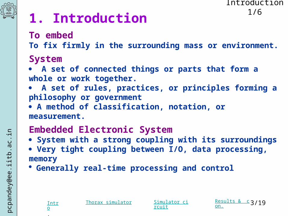
1. Introduction To embedTo fix firmly in the surrounding mass or environment.
System A set of connected things or parts that form a whole or work together. A set of rules, practices, or principles forming a philosophy or government A method of classification, notation, or measurement.
Embedded Electronic System System with a strong coupling with its surroundings Very tight coupling between I/O, data processing, memory Generally real-time processing and control
Introduction 1/6
pcpa
ndey
@ee
.iitb.
ac.in
Intro. Simulator circuit Results & con. 4/19Thorax simulator
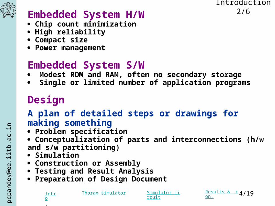
Embedded System H/W Chip count minimization High reliability Compact size Power management
Embedded System S/W Modest ROM and RAM, often no secondary storage Single or limited number of application programs
DesignA plan of detailed steps or drawings for making something Problem specification Conceptualization of parts and interconnections (h/w and s/w partitioning) Simulation Construction or Assembly Testing and Result Analysis Preparation of Design Document
Introduction 2/6
pcpa
ndey
@ee
.iitb.
ac.in
Intro. Simulator circuit Results & con. 5/19Thorax simulator
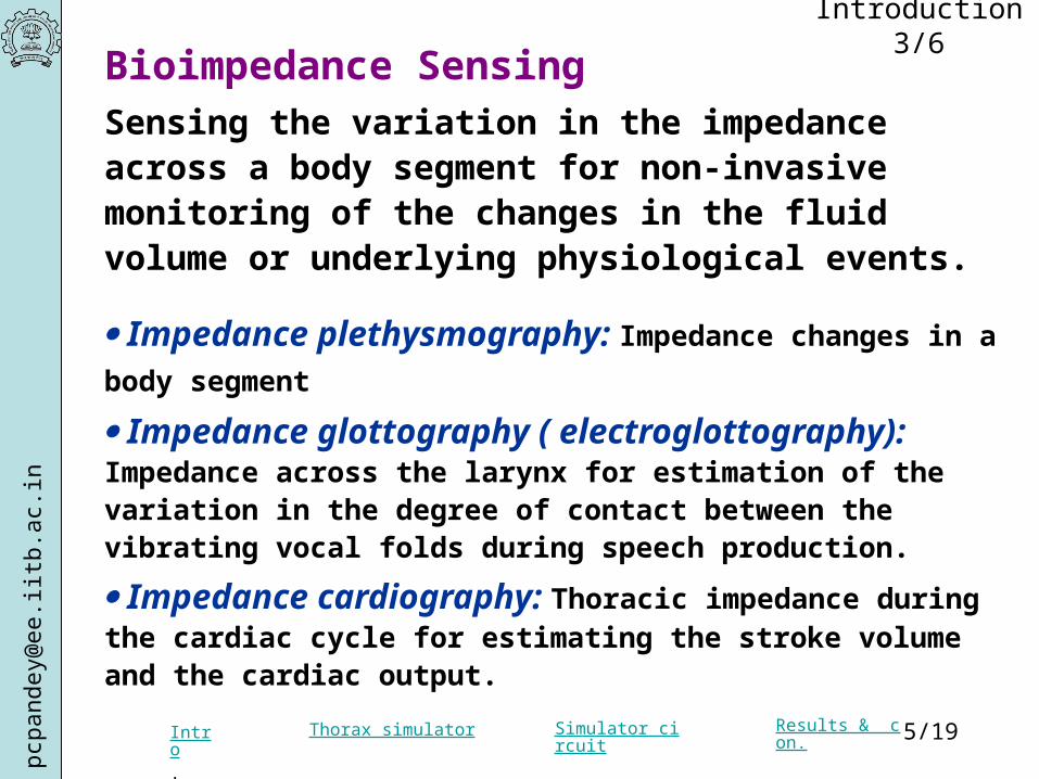
Bioimpedance SensingSensing the variation in the impedance across a body segment for non-invasive monitoring of the changes in the fluid volume or underlying physiological events.
Impedance plethysmography: Impedance changes in a body segment
Impedance glottography ( electroglottography): Impedance across the larynx for estimation of the variation in the degree of contact between the vibrating vocal folds during speech production.
Impedance cardiography: Thoracic impedance during the cardiac cycle for estimating the stroke volume and the cardiac output.
Introduction 3/6

pcpa
ndey
@ee
.iitb.
ac.in
Intro. Simulator circuit Results & con. 6/19Thorax simulator
Measurement Method
A current (20 kHz - 1 MHz, < 5 mA) passed through a pair of surface electrodes and the resulting amplitude modulated voltage sensed using the same or another pair of electrodes.
Electrode configurations- Two-electrode configuration - Three-electrode configuration (one guard electrode)- Four-electrode configuration (a more uniform current density, reduced effect of the skin-electrode impedance)
Instrumentation Challenges
- Detection of extremely low modulation index (0.2-2 %)- Rejection of interference from other sources (external sources, bioelectric sources, artifacts)
- Testing and calibration (sensitivity, frequency response)
Introduction 4/6
pcpa
ndey
@ee
.iitb.
ac.in
Intro. Simulator circuit Results & con. 7/19Thorax simulator
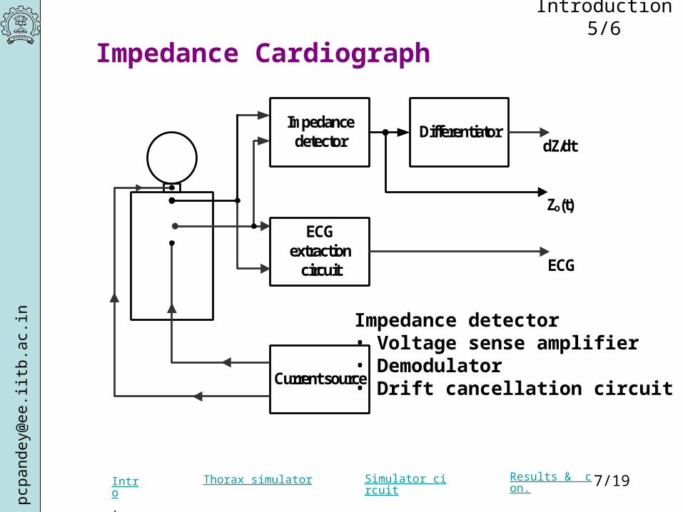
Impedance detector
ECG extraction
circuit
Current source
Differentiator
Zo(t)
dZ/dt
ECG
Impedance Cardiograph
Impedance detector• Voltage sense amplifier• Demodulator• Drift cancellation circuit
Introduction 5/6
pcpa
ndey
@ee
.iitb.
ac.in
Intro. Simulator circuit Results & con. 8/19Thorax simulator
Methods for testing and calibration
A cardiograph instrument with an internal resistance connected across the electrode terminals for calibration of the current source.
Instrument with testing mode: amplitude modulated current to simulate the modulation of the sensed voltage due to time varying impedance.
Thorax simulator - Time varying impedance for testing of sensitivity and frequency response of the impedance detector- Internal voltage source for measuring the DM gain and CMRR of the ECG amplifier in the impedance cardiograph - External source for measuring the rejection of external interference.
Introduction 6/6
pcpa
ndey
@ee
.iitb.
ac.in
Intro. Simulator circuit Results & con. 9/19Thorax simulator
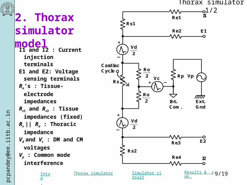
I1 and I2 : Current injection terminals
E1 and E2: Voltage sensing terminals
Re’s : Tissue-electrode
impedancesRs1 and Rs2 : Tissue
impedances (fixed) Rs || Ro : Thoracic impedance
Vd and Vc : DM and CM
voltages Vp : Common mode
interference
2. Thorax simulator model
Thorax simulator 1/2
Rp
Int. Com.
I1
E1
E2
I2
+ _
Ext.Gnd
Cardiac Cycle
+
+
Ro
2
Ro
2
Vd
2
VcRs
Rs2
Rs1
Vp
Vd
2
Re1
Re2
Re3
Re4
_
_

pcpa
ndey
@ee
.iitb.
ac.in
Intro. Simulator circuit Results & con. 10/19Thorax simulator
Schematic of thorax simulatorThorax simulator 2/2
Rp
Int. Com.
I1
E1
E2
I2
Ext.Gnd
Ry1
Ry2
Vp
Ra
Rb
Rc
Rd
Rx1
Rx2
Vx1
Vx2
Cardiac Cycle
Rv
+
_
+
_
1 1R R Rs e a 1 1R R Rs e a
2R Re b 3R Re c 2 4R R Rs e d
0 1 2 1 2R || R R R || R || R Rs y y v x x
2 1 1 1 1' 'V V / R / R R Vc d y x y x
2 2 2 2 2' 'V V / R / R R Vc d y x y x
where
1 1 2 2'R R || R R || Ry y v x y
2 2 1 1'R R || R R || Ry y v x y
Model relations with the schematic
pcpa
ndey
@ee
.iitb.
ac.in
Intro. Simulator circuit Results & con. 11/19Thorax simulator
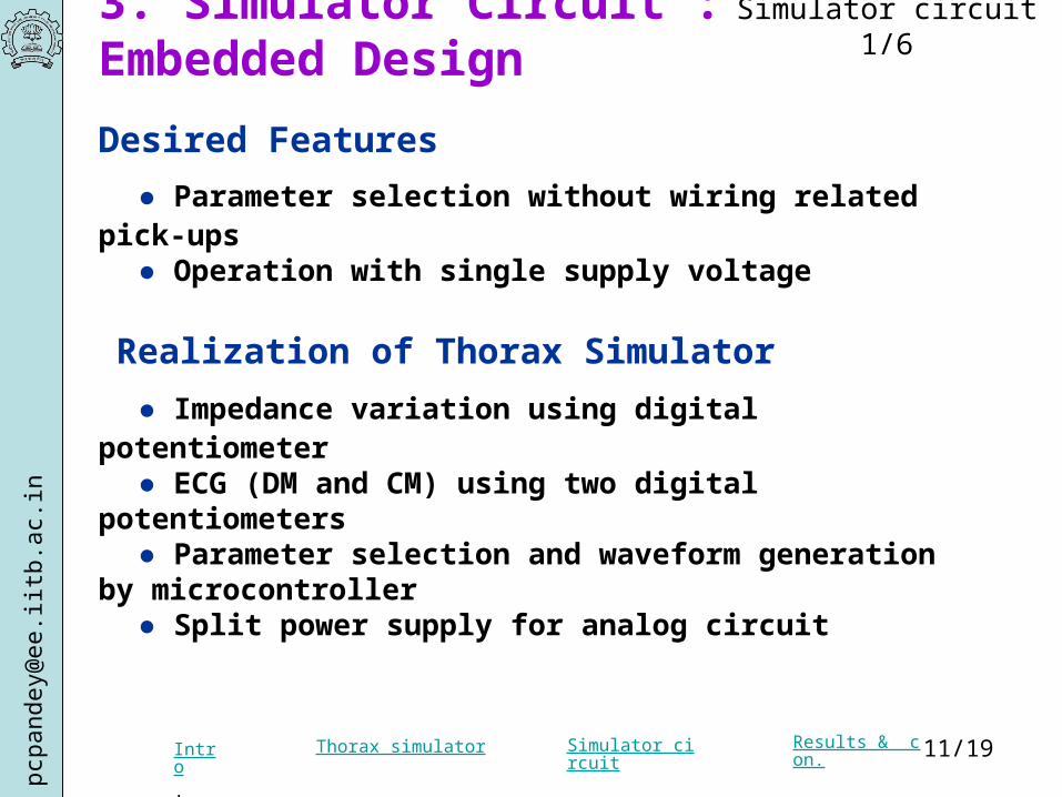
3. Simulator Circuit : Embedded Design
Desired Features
● Parameter selection without wiring related pick-ups● Operation with single supply voltage
Realization of Thorax Simulator ● Impedance variation using digital potentiometer
● ECG (DM and CM) using two digital potentiometers ● Parameter selection and waveform generation by microcontroller ● Split power supply for analog circuit
Simulator circuit 1/6
pcpa
ndey
@ee
.iitb.
ac.in
Intro. Simulator circuit Results & con. 12/19Thorax simulator
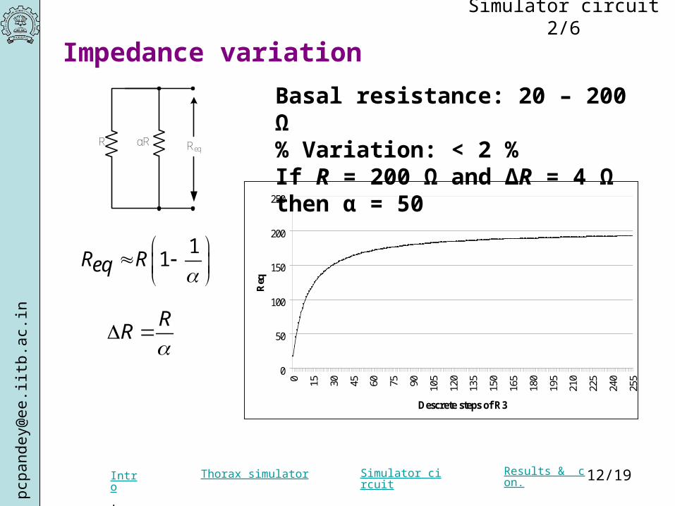
Impedance variation
R αR Req
0
50
100
150
200
250
0 15 30 45 60 75 90 105
120
135
150
165
180
195
210
225
240
255
Descrete steps of R3
Req
11R Req
RR
Basal resistance: 20 – 200 Ω % Variation: < 2 % If R = 200 Ω and ∆R = 4 Ω then α = 50
Simulator circuit 2/6
pcpa
ndey
@ee
.iitb.
ac.in
Intro. Simulator circuit Results & con. 13/19Thorax simulator
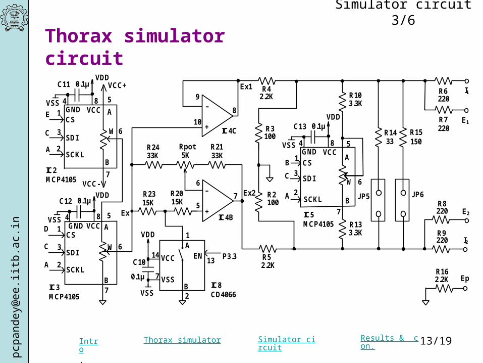
Thorax simulator circuit
Simulator circuit 3/6
R3
R2
R4 R6
R8
R9
R7
R5
IC4B
IC4C
I1
I2
E2
R24 R21
R23 R20
R14 R15
IC8 CD4066
1
2
13
7 JP5 JP6
R13
P3.3
Rpot
CS
SDI
SCKL
CS
SDI
SCKL
A
C
E
C
A
D
IC2 MCP4105
IC3 MCP4105
1
3
2
2
3
1
A
W
B
5
6
7
5
6
7
A
W
B
VCC+
VCC-
EpR16
Ex1
Ex2
9
10
8
6
5
VCCGND84
C10
0.1µ
VSS
VCC
VSS
14
7
A
B
EN
VDD
+
–
–
+
E1
33K
15K15K
33K
2.2K
2.2K
2.2K
100
100
5K
220
220
220
220
15033
3.3K
CS
SDI
SCKL
B
A
C
IC5 MCP4105
1
3
26
7
5
A
W
B
R103.3K
C11
VSS
0.1µVDD
C12
VSS
0.1µVDD
4 8GND VCC
VCCGND84
C13
VSS
0.1µVDD
Ex

pcpa
ndey
@ee
.iitb.
ac.in
Intro. Simulator circuit Results & con. 14/19Thorax simulator
CC
4.7 k
4.7 k
5
R1
R19
R22
1
2345
ABCDE
VCC+
In Out
Com
1
2
3
C60.1µ
R114.7M
R12
4.7MC70.1µ
C80.1µ
AGnd
2
3
1
IC77805
VCC-
In Out
ComS1
C9
0.1µ
1
C5
0.1µ2
3IC6
7805
C41µ
9V
C16
0.1µ
1
2Sync. Test Outputs
Digi. Pot. Control signals
IC4
+
–
IC4ALM324
VDD
VDD
VDD
VDD
4
11
10µ
0.1µ
LCD1
The controller and power supply circuit
Simulator circuit 4/6

pcpa
ndey
@ee
.iitb.
ac.in
Intro. Simulator circuit Results & con. 15/19Thorax simulator
The controller circuit
Microcontroller AT89S528 Kbytes ROM, 256 bytes RAM, 3 timers, In-system programmable
Digital potentiometers MCP 4105 (SPI controlled)
Controls: P1.0 : CLK, P1.2 : Data, P1.1, P1.3, P1.4 : Individual IC select
Lookup tables: various wave shapes (sinusoidal, square, ECG)
Synchronization test outputs: Port pins P3.6 and P3.7
User Interface: 2 line x 16 char. LCD display, two soft keys
LCD : 4-bit parallel (P2.7-P2.4), CS, RS, R/W - GND (unidirectional data flow)
Soft keys: P0.0 and P0.1 with s/w debouncing
Simulator circuit 5/6

pcpa
ndey
@ee
.iitb.
ac.in
Intro. Simulator circuit Results & con. 16/19Thorax simulator
Parameter selection
Sr. Parameters Options
1 Mode (ECG only) CM / DM
2 Type Sine / Square / ECG
3 Magnitude (ECG only) 0 100 mV (16 steps)
4 Frequency 1, 2, 4,.. 256 Hz (16 steps)
5 ResistanceVariation
0.1 1.2 % of baseresistance (12 steps)
Simulator circuit 6/6

pcpa
ndey
@ee
.iitb.
ac.in
Intro. Simulator circuit Results & con. 17/19Thorax simulator
4. Results ▪ Simultaneous simulation of bioimpedance and ECG ▪ ECG
CM: 50 - 100 mV, with < 0.2 mV DM voltageDM: 0 - 50 mV, with < 0.9 mV CM voltage
▪ Base resistance: 23.77 Ω, 28.24 Ω, 84.98 Ω,and 196.07 Ω
▪ Resistance variation: 0.1 - 1.2 % of selected base resistance

pcpa
ndey
@ee
.iitb.
ac.in
Intro. Simulator circuit Results & con. 18/19Thorax simulator
5. Conclusion
A thorax simulator developed
using embedded design approach
for testing and calibration of
the instruments for impedance cardigraphy

pcpa
ndey
@ee
.iitb.
ac.in
Intro. Simulator circuit Results & con. 19/19Thorax simulator
References
[1] J. Nyboer, Electrical Impedance Plethysmography, 2nd ed., Charles C. Thomas, Springfield, Massachusetts, 1970.[2] L. Cromwell, F. J. Weibell, and E. A. Pfeiffer, Biomedical Instrumentation and Measurements, 2nd ed., Prentice Hall, New Delhi, 1990.[3] A. K. Krishnamurthy and D. C. Childers, "Two-channel speech analysis", IEEE Trans. Acoustics, Speech Signal Proc., vol. ASSP - 34, pp. 730 - 743, 1986.[4] L. E. Baker, "Principles of impedance technique", IEEE Eng. Med. Biol. Mag., vol. 8, pp. 11 - 15, 1989.[5] R. P. Patterson, "Fundamentals of impedance cardiography", IEEE Eng. Med. Biol. Mag., vol. 8, pp. 35 - 38, 1989.[6] J. Wtorek and A. Polinski, "Multifrequency impedance plethysmograph", in Proc. IEEE Inst. Meas. Tech. Conf., Brussels, Belgium, 1996, pp. 1452 - 1455.[7] J. Fortin, W. Habenbacher, and A. Heller, "Non-invasive beat-to-beat cardiac output monitoring by an improved method of transthoracic bioimpedance measurement", Comp. Bio. Med., vol. 36, pp. 1185 - 1203, 2006.[8] F. Mora, G. Villegas, A. Hernandez, W. Coronado, R. Justiniano, and G. Passariello, "Design of an instrumentation system for a neurocardiology laboratory", in Proc. 2nd Int. Conf. IEEE Dev., Cir. and Sys., Carcas, Venezuela, 1998, pp. 272 - 277.[9] V. Vondra, J. Halamek, I. Viscor, and P. Jurak, "Two channel bioimpedance monitor for impedance cardiography", in Proc. 28th Annu. Int. Conf. IEEE Eng. Med. Biol. Soc., 2006, pp. 6061 - 6063.[10] G. Panfili, L. Piccini, L. Maggi, S. Parini, and G. Andreoni, "A wearable device for continuous monitoring of heart mechanical function based on Impedance Cardiography", in Proc. 28th Annu. Int. Conf. IEEE Eng. Med. Biol. Soc., 2006, pp. 5968 - 5971. [11] G. D. Jindal and J. P. Babu, "Calibration of dz/dt in impedance plethysmography" , Med. Biol. Eng. Comp., vol. 23, pp. 279 - 280, 1985.[12] V. K. Pandey, P. C. Pandey, and J. N. Sarvaiya, "Impedance simulator for testing of instruments for bioimpedance sensing", IETE Journal of Research, vol. 54, no. 3, pp. 203 - 207, 2008.[13] N. S. Manigandan, V. K. Pandey, and P. C. Pandey, "Thoracic simulator for impedance cardio‑ graphy", in Proc. National Symposium on Instrumentation (NSI-28), Pantnagar, India, 2003.[14] L. Venkatchalam / P. C. Pandey (Supervisor), “Development of hardware for impedance cardio‑graphy”, M.Tech. Dissertation, Biomedical Engineering Group, School of Biosciences and Bioengineering, Indian Institute of Technology Bombay, 2006.[15] B. M. Oliver, Square-wave and pulse testing of linear systems, in B. M. Oliver and J. M. Cage (Eds.), Electronic Measurements and Instrumentation, McGraw Hill, Singapore 1975.