Toyota Sudden Acceleration: A Case Study of the National ...
1
R Belt
18 March 2012 An Electronic Cause of Sudden
Unintended Acceleration
An Electronic Cause for Sudden Unintended Acceleration
by
Ronald A Belt
Plymouth MN 55447 11 April 2012
Abstract An electronic cause for sudden unintended acceleration is presented At low vehicle speeds when the
engine is at idle the alternator cannot supply all the current required by the vehiclersquos electrical system In this case
the battery must supply the additional current and the system voltage is determined by the battery voltage If the
battery state of charge is weak the battery voltage will be low and the inrush current caused by one of the vehiclersquos
electrical functions (eg an electric motor) starting up will cause a large negative voltage spike on the battery
supply line This voltage spike can pass through the ECM voltage regulators and lead to a brownout error in the
CPUs if the CPUs are not properly held in reset by the ECM supply The brownout error can cause faulty operation
of the CPUs keep-alive memory andor EEPROM memory leading to a software error that causes unpredictable
engine operation such as sudden acceleration At high vehicle speeds when the alternator is setting the system voltage worn or bouncing brushes inside the alternator can interrupt the alternator field current and produce a large
negative voltage spike on the alternator output that causes a brownout error in the CPUs These two causes provide
an alternative explanation to driver error for many observations associated with sudden unintended acceleration in
vehicles with electronically controlled throttles similar to Toyotarsquos ETCS-i system
I Introduction
Sudden acceleration has ceased to make news headlines since the NHTSA-sponsored NASA study report appeared
in February 2011 However this does not mean that sudden acceleration events have stopped occurring Safety
Research amp Strategies (SRS) a consumer safety watchdog organization has identified 330 unintended acceleration
complaints reported to the National Highway Traffic Safety Administration (NHTSA) for incidents occurring in
2011 And a separate SRS review of complaints filed with the NHTSA has identified 247 unique unintended
acceleration incidents even after Toyota had applied their two fixes for pedal sticking and floor mat entrapment
Just what is sudden acceleration A 1998 NHTSA study defined a ldquosudden acceleration incidentrdquo as an
ldquounintended unexpected high-power acceleration from a stationary position or a very low initial speed
accompanied by an apparent loss of braking effectivenessrdquo For twenty years this definition has been used by the
NHTSA to characterize data perform investigations and draw conclusions regarding sudden acceleration It has also been used by automobile companies to make recalls and by the US courts to settle suits brought against
automobile manufacturers Its dual requirements of a) ldquoacceleration from a stationary or very low initial speed
positionrdquo and b) ldquoloss of braking effectivenessrdquo along with the results of several NHTSA-sponsored studies that no
causal connection can made between throttle operation and brake operation have influenced NHTSA to conclude
that the only way a sudden acceleration event can happen is either by two independent faults causing phenomena a)
and b) simultaneously or by the driver himself causing the incident due to pedal misapplication Since NHTSA
believes that both such faults must leave physical evidence and since no study has proven the existence of two such
faults by means of physical evidence NHTSA has concluded that all sudden acceleration incidents are the result of
pedal misapplication by the driver
A more recent NHTSANASA report in 2011 defines ldquounintended accelerationrdquo as ldquothe occurrence of any degree of acceleration that the driver did not purposely cause to occurrdquo It is intended to be a broader term that encompasses
ldquosudden acceleration incidentsrdquo as well as incidents where brakes are partially or fully effective including
occurrences such as pedal entrapment by floor mats at full throttle and high speeds and incidents of lesser throttle
openings at various speeds Despite this more general definition NHTSA claims in their latest NASA report that
ldquoNo mechanism has been identified that could cause the throttle to open because of brake application and any
engine power increases that may occur during a brake application should be easily controllable by the driverrdquo1
Therefore NHTSA concludes once more from this study that all sudden acceleration incidents are caused by pedal
misapplication by the driver Their conclusion disregards the claims of thousands of drivers that their foot was on
the brake when sudden acceleration started and effectively implies that the drivers were either unwittingly mistaken
or knowingly lying about the location of their foot when sudden acceleration occurred It also turns a blind eye to
2
R Belt
18 March 2012 An Electronic Cause of Sudden
Unintended Acceleration
the fact that sudden acceleration incidents have happened to policemen Toyota and other dealer repair technicians
and chauffeurs trained in emergency vehicle maneuvers
It is difficult for this author to believe that such a large number of drivers are either mistaken or lying about the
position of their foot On the other hand the author believes that if such a large number of drivers are making the
same claims about unintended acceleration then perhaps there is some truth to these claims If the claims are indeed true they may be telling us something about how unintended acceleration begins Therefore this paper will start
with driversrsquo first-hand observations about unintended acceleration and try to use these observations as clues to
deduce the cause of sudden acceleration
The following is a list of known observations and facts about sudden unintended acceleration as compiled by the
author The term ldquosudden unintended accelerationrdquo has been used intentionally to avoid any categorization of the
incidents according to either NHTSArsquos 1989 definition or NHTSANASArsquos 2011 definition
1 During a sudden unintended acceleration incident the engine RPMrsquos suddenly increase above what the
driver considers to be normal Sometimes the RPMrsquos increase to a wide open throttle state (gt6000 RPM)
But other times they increase to only 2000 to 3000 RPM or less
2 The majority of sudden unintended acceleration incidents (92) occur at low speeds (lt15 mph)2 (Fig 1)
3 More low-speed sudden unintended acceleration incidents (49) occur when entering a parking space than when leaving a parking space (12)
3 (Fig 2)
Fig 1 MY2002 ndash 2006 consumer complaints
by initiation speed Pre-5-Oct-092
Fig 2 Breakdown of low speed sudden acceleration
incidents by vehicle operations in progress3
4 A majority of drivers (62) steadfastly maintain that sudden unintended acceleration occurred while their
foot was on the brake A small number of others have mentioned that it occurred when shifting out of
PARK
5 A disproportionate number of sudden unintended acceleration incidents involve drivers over age 60
including some in their seventies and even eighties 4 (Fig 3)
a It has happened to policemen chauffeurs FBI agents trained in evasive car maneuvers and even Toyota repairmen
b It has happened to the same person in two different vehicles at least six times
c It has been witnessed once by two NHTSA personnel who verified that the accelerator was not
involved
Fig 3 Number of sudden acceleration incidents
versus driverrsquos age4
Fig 4 Alleged unintended acceleration complaints
per 100K vehicles MY 1998-20105
3
R Belt
18 March 2012 An Electronic Cause of Sudden
Unintended Acceleration
6 Sudden unintended acceleration incidents have occurred with all makes of automobiles Toyota and Volvo
have the highest incidence rates and General Motors has the lowest incidence rate5 (Fig 4)
7 Sudden unintended acceleration occurs rarely The incident rate is less than 12 incidents per 100K vehicles
(lt120 ppm)5 (Fig 4)
8 Sudden unintended acceleration incidents have occurred in Toyota hybrid vehicles like the Prius 9 Sudden unintended acceleration incidents occur rarely with police cars even though they are used a lot at
low speeds
10 When the ignition is turned on again after it has been turned off following a sudden unintended acceleration
condition the engine RPMrsquos nearly always resume in a normal low state That is recycling the ignition
nearly always removes the sudden unintended acceleration condition
11 Sudden unintended acceleration occurs most often in autos having an automatic transmission and throttle
by wire But it has also occurred in autos having a stick shift or a conventional mechanical throttle
12 Sudden unintended acceleration appears to have a higher rate of incidence in the USA than in Canada or
Europe
13 Drivers often complain that during sudden unintended acceleration the vehiclersquos brakes were ineffective
either partially or totally
14 Some drivers have heard the ABS pump activate just before sudden unintended acceleration occurred 15 If a crash occurs as a result of sudden unintended acceleration sometimes the front airbags do not deploy
even though damage to the vehicle is extensive
16 Sudden unintended acceleration is a very intermittent condition It has not been reproduced on demand
17 If a vehicle has ever experienced sudden unintended acceleration it has a higher probability of
experiencing it again at some later time
18 Sudden unintended acceleration can occur with the vehicle going either forward or backward
19 In a few cases voltage measurements taken after sudden unintended acceleration incidents have shown low
voltages
II The Path Toward an Electronic Cause of Sudden Acceleration
Our search for an electronic cause of sudden acceleration starts with observation 2 above ie that the majority of
sudden unintended acceleration incidents (92) occur at low vehicle speeds (lt15 mph) These incidents usually
occur in parking lots driveways or when approaching an intersection stop sign or traffic light
Implications of Low Speed Operation Let us examine what is happening to the vehicle during normal operation at
low speeds such as in parking lots driveways or when approaching a stop sign or traffic light Certainly one thing
that is happening in these situations is that the engine is running a lot at idle This is because the driver wants to
operate the vehicle slowly to avoid pedestrians maneuver in tight quarters or obey traffic laws and avoid possible
traffic accidents and keeps his foot off the accelerator and usually on the brake When the vehiclersquos engine is
running at idle we ask what is happening to the vehiclersquos electrical system One thing that is certainly happening is
that the vehiclersquos alternator is operating at its minimum efficiency because its current output depends upon its
rotational speed and its rotational speed is tied directly to the engine speed (the ratio of alternator speed to engine
speed is about 271) Therefore at idle the alternator is supplying a minimum amount of output current to the
vehiclersquos electrical system Fig 1 shows how the alternator current output varies with alternator speed for a 140 amp
alternator One sees that a nominal 140 amp alternator puts out only about 50 or 70 amps at engine idle speed at
20degC This amount decreases even further as the alternator temperature rises as shown in Fig 2 At 100degC which is a normal operating temperature for an engine compartment the 140 amp alternator can put out only about 110 amps
at high speeds and only about 59 amps at idle This is only about 40 of the 140 amp nominal rating Considering
that most Toyota vehicles have only 80 amp or 100 amp alternators instead of the 140 amp alternator shown in Figs
5 and 6 one can conclude that the alternators of Toyota vehicles are putting out only about 32 to 40 amps at idle
4
R Belt
18 March 2012 An Electronic Cause of Sudden
Unintended Acceleration
Fig 5 Alternator output current versus
rotational speed for a 140 amp alternator6
Fig 6 Alternator output current decreases
as the operating temperature increases7
How does this compare with the demand for current by the vehiclersquos electrical system Table 1 lists the components
(ie current loads) in a typical vehiclersquos electrical system The current loads are organized into two major columns
a) the left hand major column contains current loads which are active at any vehicle speed and b) the right hand major column contains current loads which are active mostly at low vehicle speeds The current loads in each major
column are further divided into DC current loads (ie direct current or steady current loads) and PWM current loads
(ie pulse width modulated loads or loads that are supplied with a pulsed battery current having a variable pulse
width) The left hand major column also contains aftermarket accessory loads which some drivers may add to their
vehicle and which are all DC current loads In each major column the individual current loads are listed along with
an estimate of their steady state current (which is the time-averaged current in the case of PWM loads) their inrush
current and their fuse size (which is usually about 15x to 2x higher than the current load to allow for normal current
variation) These estimates may vary from one auto manufacturer to another due to design details but usually are
similar across the manufacturerrsquos various models In this table the values correspond to Toyota Camry and Lexus
ES350 vehicles While the author has attempted to be as accurate as possible some of the estimates may have a
slight error because of design differences between Toyota models and the variety of sources from which the
estimates have been taken (no auto manufacturer provides this information to the public) However the estimates are believed to be accurate to within about 20 We will have more to say about the inrush currents later in this
paper
Not all of these current loads are active at the same time If we add up the current loads that are usually active at
one time we find that the vehicle requires between 57 and 87 amps at any speed (depending upon whether the air
conditioning system is being used) with another 10 to 76 amps required at low speeds (depending upon whether the
cooling fans and ABS brakes are being used) This gives a total of 67 to 163 amps required at low speeds which is
a much higher current than the alternator can supply at idle speed (32 to 40 amps for a Toyota 80 to 100 amp
alternator) This is not an error in our estimates It merely means that at idle the battery is supplying the additional
current that the electrical system requires When this happens the system voltage changes from the alternator
voltage used to charge the battery (143V) to the battery voltage itself (126V for a fully charged battery) This has very little effect on the operation of the electrical system loads because the voltages are so similar When this
happens the battery also discharges slightly But as soon as the vehicle resumes operation at higher speeds the
alternator current output increases the battery stops supplying current the system voltage jumps back up to the
alternator voltage of 143V and the battery begins to charge up again This is the way the battery and alternator are
supposed to operate However if vehicle remains at idle for a long time and the battery must supply this additional
current for a long time the battery will discharge even further This can cause the battery voltage to drop below
126V or even much lower If the battery voltage drops significantly below 126V then its effect on electrical
system operation will be noticeable by the driver as a dimming of the headlights andor a dimming of the dashboard
lights The following changes also occur at lower system voltages
1 Electric motors rotate slower and may not start at all (eg HVAC blower motor or ABS pump motor)
2 Electric motor starting current increases
3 Relays and solenoids may chatter and at a low enough voltage may revert to their non-actuated state 4 Voltage regulators can go out of regulation
5 Sensors can start making errors or may stop sensing completely
5
R Belt
18 March 2012 An Electronic Cause of Sudden
Unintended Acceleration
Table 1 Current loads in a typical vehiclersquos electrical system
Back in 1997 so many GM customers complained about this variation in light intensity at idle that GM was forced
to publish technical bulletin 43-64-07A issued in January 1997 to put its customers at ease8 It reads
Subject Low Voltage Reading or Dim Lights at Idle
Models 1990-97 Passenger Cars and Trucks
Discussion
Any vehicle may have a low voltage reading (if equipped with gauges) or lights that dim
when electrical loads are heavy at idle or under very slow driving conditions This condition may be worse with owner added electrical accessories or with a discharged battery THIS
CONDITION IS A NORMAL OPERATING CHARACTERISTIC OF THE VEHICLE AND NO
REPAIRS SHOULD BE ATTEMPTED UNLESS A PROVEN FAULT HAS BEEN FOUND
At idle vehicle electrical loads may exceed the low speed output of the generator but the
battery can make up for this shortfall from its reserve capacity for short periods During normal
driving conditions the generator is designed to do two things supply the necessary vehicle loads
and recharge the battery Long periods of battery discharge due to high accessory loads at idle will
cause the electrical system voltage to drop as the battery continues to deliver the electrical power
Increased generator temperatures from extended idling can also contribute to lower electrical
6
R Belt
18 March 2012 An Electronic Cause of Sudden
Unintended Acceleration
system voltage As temperatures rise the voltage set point is reduced to avoid battery overcharge
and the generators output capability is reduced due to increased electrical resistance
Depending on the vehicle application normal generator output at idle can be as low as 35
of the full rated output With enough electrical loads it is easy to exceed the low speed generator
output at idle This is a NORMAL condition that the battery can compensate for during short
periods Items that affect the vehicle system voltage at idle are driving conditions the number of electrical loads being used add-on accessories and extended idle times Normal driving
conditions will recharge the battery and restore the charging system to its normal state
GM issued another technical bulletin in 2002 that elaborated on this condition Here is GM technical bulletin 02-
06-03-008 dated August 2002 in its entirety9
Title Charging System - Low Voltage Display ONDim Lights
File In Section 06 - EnginePropulsion System
Subject Low Voltage Display on IP Gauge Lights Dim at Stop Lights Battery Discharged No
Start Slow Cranking Dim Lights at Idle Low Generator Output
Models 1990-2003 Passenger Cars and Light Duty Trucks
2003 HUMMER H2
Discussion This bulletin is being revised to update the model years and to update text Please discard
Corporate Bulletin Number 43-64-07A (Section 06 - Engine)
Any vehicle may have a low voltage display (if equipped with gauges) lights that dim at
stop lights slow cranking no start low generator output at idle or dim lights at idle when
electrical loads are heavy at idle or under slow driving or infrequent usage conditions These
characteristics may be more noticeable with customer added electrical accessories or with a
discharged battery These are normal operating characteristics of a vehicle electrical system and no
repairs should be attempted unless a proven fault has been diagnosed
During normal driving conditions when engine speed is above 1000 RPM the generator
is designed to do two things
1) Supply the current necessary to operate the vehicles originally equipped electrical devices (loads)
2) Recharge maintain the batterys state of charge
The following factors may affect generator and battery performance
a) Non-usage of the vehicle for extended periods of time The vehicles
computers clocks and the like will cause the battery state of charge to drop (For example 30 days
in a parking lot and the vehicle may not start because of a dead battery or a vehicle which is driven
to church only on Sunday may end up with a discharged battery to the point where the vehicle
may not start) This would be considered abnormal usage of the vehicle and the normally expected
result for the vehicle battery generator and electrical systems
b) At idle vehicle electrical loads may exceed the low speed current (amperage)
output of the generator and when this happens the shortfall comes from the battery This will result
in a drop in the electrical system voltage as the battery delivers the additional electrical current to meet the demand This is equivalent to the brown outs experienced by homes and businesses when
the electrical demand is more than the supply See Figure 1
c) Extended periods of engine idling with high electrical loads may result in a
discharged battery Attempting to recharge a battery by letting the engine run at idle may not be
beneficial unless all electrical loads are turned OFF
d) Increased internal generator temperatures from extended idling can also
contribute to lower electrical system voltage As the generators internal temperature rises the
generators output capability is reduced due to increased electrical resistance
Table X shows some typical examples of electrical loads
7
R Belt
18 March 2012 An Electronic Cause of Sudden
Unintended Acceleration
Table X Some typical electrical loads
LOAD AMPS
Rear window defogger 25
Headlamps (low) 15
Headlamps (high) 20
High blower 20
Windshield wipers 6
Ignition 6
Brake lights 5
Depending on the vehicle application generator current (amperage) output at engine idle speeds of 600-700 RPM can be as low as 35 percent of the full rated output With enough
electrical loads ON it is easy to exceed the generator current (amperage) output when the engine
is at an idle of 600-700 RPM This is a normal condition The battery supplements for short
periods of time Items that affect the vehicles electrical system current and voltage at idle are the
number of electrical loads being used including add-on accessories and extended idle times
When the vehicle speed is above approximately 24 kmh (15 mph) the enginegenerator RPM is
high enough and the generator current (amperage) output is sufficient to supply the current
(amperage) requirements of the vehicle as originally equipped and recharge the battery
Dimming lights at idle may be considered normal for two reasons
1 As the enginegenerator speed changes so will the current (amperage) output
of the generator As a vehicle slows enginegenerator RPM slows and the current (amperage) output of the generator may not be sufficient to supply the loads the vehicle system voltage will
drop and the lights will dim Dimming of the lights is an indication that current is being pulled
from the battery If the battery is in a low state-of-charge (discharged condition) the driver will
notice a more pronounced dimming than a vehicle with a fully charged battery
2 When high current loads (blower rear defogger headlamps cooling fan
heated seats power seats electric AIR pump or power windows) are operating or cycled ON
the generators voltage regulator can delay the rise in output This effect usually at lower engine
speeds can take up to ten seconds to ramp up the generator output This is done to avoid loading
the engine severely To increase current (amperage) output additional torque is consumed by the
generator The engine computer (PCM) will ramp up enginegenerator speed in small steps so
engine speed variations are not noticeable to the driver
For diagnosis of the battery and or the generator refer to the appropriate Service Information or Corporate Bulletin Number 02-06-03-006
GMrsquos technical bulletins have become even more relevant in recent years as the electrical content of
automobiles has increased Figure 7 shows how the average electrical load has increased and Figure 8
shows how the nominal current of the fuses and the installed alternator power has increased It is expected
that these trends will continue as the introduction of electronic power steering electronic stability control
adaptive cruise control electronically tuned suspension and electronic brake by wire becomes more
widespread
Fig 7 Increase of the average electrical load Fig 8 Increase of the total nominal current of the fuses
42
83
125
167
0
208
Ave
rage
Lo
ad (
am
ps)
(w
atts
)
8
R Belt
18 March 2012 An Electronic Cause of Sudden
Unintended Acceleration
of an automobile versus model year10 (left scale) and the installed alternator power
(right scale) in the latest decades11
DC Battery Voltage Having seen that idle operation can result in low battery voltage we now ask how low a
battery voltage is possible If one draws a constant current from a lead acid battery and measures the voltage versus
time one gets a curve like that shown in Fig 9 for a constant current of about 18 amps After about 10 hours the battery becomes fully discharged and a voltage of 105V is measured When the current is turned off the battery
voltage bounces back up to about 115 volts due to surface charge in the battery Fig 10 shows a similar curve for a
Delco Legend 50Ah battery discharged by about a 55 amp constant current Fig 11 shows how the shape of this
curve explains how the batteryrsquos ability to absorb (ie filter) voltage fluctuations decreases with decreasing state of
charge (SOC) Fig 12 shows how these curves vary with increasing discharge rates
Fig 9 How battery discharge curves
are measured at constant current12
Fig 10 Measured constant current discharge
curve for a 50Ah Delco Legend battery13
Fig 11 Discharge curve showing how the battery
absorbs voltage variations at different SOCrsquos14
Fig 12 Manufacturerrsquos discharge curves for the
Yuasa DM55-12 55Ah 12V battery15
The shape of the above discharge curves is determined by the batteryrsquos internal construction Figure 13 shows a
simplified model of a lead-acid cell It consists of a capacitor which represents the batteryrsquos charge storage
capability a series resistance Rmetallic which has several components and a parallel resistance Relectrochemical which has
several components When measuring the constant current discharge curves the voltage drops across the series and parallel resistances are included in the voltage measurement However if we measure the battery voltage using a
high impedance voltmeter while no current is flowing then we obtain a different voltage called the battery open
circuit voltage which is the voltage drop across the capacitor when these internal resistances are absent This
voltage is plotted in Fig 14 as a function of the battery state of charge (SOC) From these two measurements the
battery internal series resistance can be derived as shown in Figs 15 and 16 Figs 15 and 16 show that the battery
internal series resistance varies with the battery state of charge (SOC) by about a factor of 3 to 10 from a fully
charged battery (100 SOC) to a fully discharged battery (0 SOC) depending on the actual battery construction
Table 2 summarizes these two battery model parameters for the two extremes of battery operating condition (SOC)
Conversely knowing the batteryrsquos open circuit voltage and its series resistance one can now calculate the batteryrsquos
terminal voltage This makes it easy to calculate the voltage across any electrical load we add to the battery
9
R Belt
18 March 2012 An Electronic Cause of Sudden
Unintended Acceleration
because we only need to calculate the voltage drop across the batteryrsquos internal resistance that is caused by the
imposed electrical load current and subtract it from the batteryrsquos open circuit voltage
Fig 13 Simplified model of a lead-acid cell1617 Fig 14 Open circuit voltage versus
state of charge (SOC) for a lead acid battery18
Fig 15 Internal resistance as a function of SOC
for a typical lead acid battery19
Fig 16 Internal resistance as a function of SOC
for a different lead acid battery20
Table 2 Battery model parameters for the two extremes
of battery state of charge (SOC)
Calculating the DC Voltage at the ECM We can now calculate the DC voltage applied to an ECM by using our
knowledge of the batteryrsquos internal series resistance along with a circuit diagram of the automobilersquos electrical
system and a knowledge of the load currents listed in Table 1 Fig 17 shows a simplified circuit diagram of the
electrical system in a 2005 Camry Fig 18 shows the locations of each of the electrical components in the vehicle
In Fig 17 if we follow the current path in red we can see that the current to the ECM flows from the batteryrsquos
positive terminal through a fusible link through a red battery cable through relay block No 1 through junction
block No 1 through an instrument panel junction block and through a harness splice point under the dash The
current back to the battery flows from the ECM through two ground bolts on the engine cylinder head through the engine through a braided connector to a ground bolt on the passenger side fender through the chassis to a ground
bolt on the driver side of the radiator through a black battery cable to the batteryrsquos negative terminal Fig 17
includes the ldquobig threerdquo battery cables that are important to electrical system operation and which are usually not
included in manufacturerrsquos circuit diagrams (the two ground cables are usually replaced by a triangular ground
symbol) Fig 17 also includes the current path through the skid control ECU It is interesting to note that Toyota
10
R Belt
18 March 2012 An Electronic Cause of Sudden
Unintended Acceleration
uses two different ABS brake systems in the 2005 Camry one for vehicles made in the USA (TMMK ndash where K
stands for Kentucky) and the other for vehicles made in Japan (TMC) The USA-made ABS system (believed to be
a Bosch ABS unit) uses mechanical relays outside of the ECU whereas the Japanese-made ABS (believed to be a
Denso ABS unit) uses electronic relays inside the ECU
Fig 17 Simplified wiring diagram of a 2005 Camry
showing the power train ECM current path21
Fig 18 Locations of the electrical
components in a 2005 Camry22
In making our calculation of the DC voltage applied to the power train ECM we must include the voltage drops not
only in the supply side to the ECM but also in the ground side from the ECM back to the battery Figure 19 shows
how both of these voltage drops contribute to the voltage across the ECM Fig 20 shows more clearly how the
voltage at a component like an ECM depends upon the current path to that component In calculating the individual
voltage drop for each component we must also use the total current through the component if the component also
lies in a current path for other electronic functions as well as the power train ECM current path
Fig 19 Voltage at different measurement points
between the battery and an ECM23
Fig 20 Voltages measured at the alternator (T1) a
distribution box (T2) and terminals of an ECM (T3)24
Table 3 shows the results of our calculation of the ECM voltage The calculation is more of an estimate than a detailed calculation because all connector drops have been approximated by the same one milliohm resistance and
all cables have been approximated by the same 05 milliohm resistance Also the voltage drops across the fusible
link relays and fuses have been neglected Nevertheless the table shows how such a calculation is done The
results are affected little by these approximations The results show that the voltage drop at the power train ECM
11
R Belt
18 March 2012 An Electronic Cause of Sudden
Unintended Acceleration
varies from 111 volts to 83 volts as the battery SOC decreases from 100 to 0 Even the lowest voltage 83
volts will not cause a problem in most vehicle electrical systems
Table 3 Calculation of voltage across the power train
ECM for two extremes of battery conditions
Table 4 Derivation of currents
used in Table 3
Fig 21 shows the results of a similar calculation for the battery voltage in a vehicle with electric power steering
(EPS) which uses a lot of current (80 amps) When the brakes are actuated the battery voltage dips to 118 volts
and when the EPS is actuated the battery voltage dips to less than 9 volts Fig 22 shows that the battery voltage
drops continuously as the battery discharges from 96 to 87 SOC Since larger vehicles require EPS motors with
higher torque and higher torque means higher load current this is the main reason why EPS is used only on smaller
vehicles at this time
Fig 21 Battery voltage changes with
braking current (A) and electric power
steering current (B)25
Fig 22 Battery voltage (top trace) and
SOC variation (bottom trace) for repeated
exercising of steering and braking26
Figs 23 24 and 25 show how the resistance of electrical connections can increase over time with corrosion This type of corrosion is galvanic corrosion which is enhanced by the current across the junction between the dissimilar
metals This corrosion can become so bad that the entire connector can be consumed which creates an open in the
current path The corrosion can also form under the paint under a chassis ground bolt making it appear as though
corrosion is absent This aging effect is present in all vehicles but was not included in the voltage drop calculations
above Battery terminal corrosion directly adds to the batteryrsquos internal resistance It is very important therefore to
keep battery terminals clean and free of corrosion
12
R Belt
18 March 2012 An Electronic Cause of Sudden
Unintended Acceleration
Fig 23 Corrosion on a battery
terminal Corrosion can also
migrate 6 inches up the cable27
Fig 24 Corrosion in a radiator
fan motor connector28
Fig 25 Connection of a ground strap
to a chassis ground bolt29
Inrush Currents We will now discuss the inrush currents that we deferred while discussing Table 1 These inrush
currents are of several types as shown in Table 5 They all produce negative voltage spikes Resistive loads such
as heating elements and rear window defrosters have an inrush current equal to their steady state current value
because their resistance does not change Inductive loads such as solenoids relays and clutches have an inrush
current that builds up slowly while energy is being stored in the magnetic field After the magnetic field has reached
its maximum value the load behaves like a resistor until turn-off when the energy in the magnetic field is released
as the field collapses This creates a huge voltage spike on turn-off which can be useful (as with ignition coils) or
which must be suppressed using diodes or snubbers (as with relay coils) Capacitive loads such as filter capacitors
in ECUrsquos have a large inrush current at turn-on because the current initially sees the full voltage across the
uncharged capacitor As the capacitor charges with an exponential time constant (determined by the RC time
constant of the capacitor and any series resistance) the current drops to nearly zero The current then stays low while the voltage remains on The ratio of the initial current spike to the steady state current value is about a factor
of 5 An incandescent lamp such as a headlamp tail lamp or flasher lamp has a current waveform similar to a
capacitor but for a different reason When the lamp is first turned on the resistance of the filament is very low
because it is a metal conductor like tungsten As current continues to flow the resistance of the filament increases
which reduces the current through the filament After reaching a maximum temperature the filament resistance
ceases to increase and the current reaches a steady state value It then stays at its steady state value until it is turned
off The ratio of inrush current spike to the steady state current is about a factor of 5
13
R Belt
18 March 2012 An Electronic Cause of Sudden
Unintended Acceleration
Table 5 Types of inrush currents In a motor vehicle these currents
all draw current from the battery and produce negative voltage spikes
Load Examples Typical Current
Waveform Inrush Current
(X = Steady State current)
Resistive Heating elements
rear window defroster
1
Inductive Solenoids relays clutches ignition
coils
1
Capacitive Filter caps in ECUrsquos (eg PWM ABS air
bag ECUrsquos)
~5X
Incandescent Lamp
Headlamps tail lamps flashers
~5X
Motor Pumps fans blowers
5X to 10X
Electric motors behave in a more complicated fashion as shown in Fig 26 When a motor is first turned on the
windings in the motor behave like a very low value resistor which creates almost a direct short to ground Larger
motors have smaller winding resistances causing larger inrush currents As the motor begins to spin the spinning
rotor interacts with the stationary stator coils to produce a voltage (called a counter-EMF) which opposes the initial
voltage applied to the motor This reduces the current through the motor which reaches a steady state value as the motor speed becomes constant The ratio of the inrush current to the steady state value is about a factor of 5 to 10
times depending on motor size A slower rotational speed means a smaller counter-EMF voltage and a higher
steady state current through the motor A slower rotational speed may be the result of a heavy load on the motor
due to either a greater load imposed by the external accessory connected to the motor or due to friction in the
bearings inside the motor itself (due to wear or to dimensional changes imposed by high temperatures) A slower
rotational speed also may be the result of a lower applied voltage which makes the motor run slower If the motor
does not rotate at all it is said to be seized or stalled and the counter-EMF in this case is zero This condition can
happen for a variable length of time called the stall duration which can last many seconds or minutes (or even
longer) During this time the motor current stays at its maximum value called the stall current After some arbitrary
time the motor can start rotating again to cause the current through the motor to decrease as normal
Electric motors in an automobile can be powered either by a continuous battery DC current as with most radiator
fans and HVAC blowers or by a pulse width modulated (PWM) battery voltage waveform such as throttle motors
ABS brake pumps windshield wipers fuel pump and nearly all remaining electric motors on the vehicle In the
case of PWM excitation it is the time-averaged DC current that is relevant to the motor operation shown in Fig 26
This makes it difficult to add the inrush currents produced by two different PWM-controlled motors because the
motor currents are rarely in phase However there are two ways in which the inrush currents of two motors can add
In the first way if one motor powered by a DC current (eg a radiator fan motor) is started and stalls temporarily
then a second motor (eg an ABS pump motor) started during the stall will add its inrush current to the first motorrsquos
stall current The second way applies to some PWM-controlled motors used in applications requiring a high starting
torque (eg an ABS pump) These PWM-controlled motors are designed to start in the direct current mode which
produces a higher starting torque After a counter EMF voltage is detected the controller switches the drive
waveform to the PWM mode In this case if the motor is started and temporarily stalls the PWM mode is never entered During the stall duration it is then possible for a second motor (eg a radiator fan motor) to add its inrush
current to the inrush current of the stalled motor (eg ABS pump motor) as shown in Fig 27 These two cases can
produce a giant current spike of approximately twice the magnitude of a single current spike
14
R Belt
18 March 2012 An Electronic Cause of Sudden
Unintended Acceleration
Fig 26 Current drawn by a 150W (12 amp) DC motor
showing how the steady state current varies with
rotational speed reducing to the stall current
when completely stopped or seized30
Fig 27 If a motor is stalled at start-up the inrush current
of a second motor may add to the inrush current of the
stalled motor to produce a giant current spike of
approximately twice the magnitude
Inrush current waveforms for all the current loads listed in Table 1 are shown in Appendix 1 The reader can view these to get a better understanding of their shapes and values The inrush currents of these waveforms have been
extracted and included in Table 1 as the inrush current values These inrush current values can now be added to the
steady state currents to determine the effect of a voltage spike caused by a particular inrush current or combination
of inrush currents
For example we can calculate the effect of a radiator cooling fan start-up spike by including the radiator fan inrush
current in the calculation of Tables 3 and 4 above The result is shown in Tables 6 and 7 below We see that the
radiator fan inrush current (one of the largest) when added to the existing steady state current load produces a
voltage dip across the power train ECM of 104 volts with a fully charged (SOC = 100) and 77 volts with a fully
depleted battery (SOC = 0) At battery charges between these two extremes the voltage dip will be between 104
volts and 77 volts Any voltage below 8 volts will cause a CPU reset to occur as discussed below
Table 6 Calculation of voltage across the power train
ECM for two extremes of battery conditions
assuming a radiator fan inrush current
Table 7 Derivation of currents
used in Table 6
The important thing to remember is that all of these inrush currents are present in the electrical system at all times
Whether they can cause a voltage at the ECM below the 8 volt limit is determined by the state of charge (SOC) of
the battery If the battery is fully charged (SOC = 100) the inrush currents will cause a voltage drop at the ECM
of only 104 volts or above However if the battery is fully discharged (SOC = 0) the voltage may drop as low as
15
R Belt
18 March 2012 An Electronic Cause of Sudden
Unintended Acceleration
77 volts With intermediate levels of battery charge or with any of the other (smaller) inrush currents the voltage
at the ECM will fall somewhere between 104 volts and 77 volts One might say that a weak battery or low battery
activates the existing inrush current spikes causing the voltage at the ECM to drop momentarily to a value below 8
volts at which a CPU reset will occur
For example Fig 28 shows that the inrush current of large radiator fan will cause the battery voltage to drop to only 10 volts if the battery is fully charged As another example Fig 29 shows that with a fully charged battery ABS
brake inrush currents of over 100 amps will cause the battery voltage to fall from 143V to only 141V and the
voltage at the ABS ECU from 143V to only 115V
Fig 28 With a fully charged battery a radiator fan
with a large inrush current of 100 amps causes the
battery voltage to drop to only about 10 volts31
Fig 29 With a fully charged battery ABS brake
inrush currents of over 100 amps will cause the battery
voltage to drop from 143V to only 141V and the
voltage at the ABS ECU from 143V to only 115V32
However as the battery internal resistance increases due to a weak or low battery condition caused by internal
corrosion or sulfation the existing inrush current spikes cause the battery voltage to spike to lower and lower values
Fig 30 for example shows that two inrush currents of constant size will produce larger voltage spikes as the battery
state of charge (as indicated by the changing specific gravity) decreases Fig 31 shows that the battery voltage drop
during starter operation is greater as the battery internal resistance increases Corrosion of the battery terminals the
ldquobig threerdquo battery cables or the chassis ground bolts will add resistance in series with the batteryrsquos internal
resistance and produce the same effects A shorted battery cell which drops the battery voltage from 126V to 105V will also produce the same effects
Fig 30 Two inrush currents of constant size produce
larger voltage spikes as the battery state of charge
(as indicated by the changing specific gravity) decreases33
Fig 31 Battery voltage drop during starter operation
varies from 77V to 58V as the battery internal
resistance increases (simulation)34
Fig 32 shows a conceptual illustration of how the voltage spike associated with an inrush current has a noise margin
above some critical voltage V0 when sitting on the battery voltage of a fully charged battery Fig 33 shows how this
16
R Belt
18 March 2012 An Electronic Cause of Sudden
Unintended Acceleration
same voltage spike falls below the critical voltage V0 when sitting on the battery voltage of a low or weak battery
The battery voltage has dropped due to a decreased open circuit voltage and the spike has grown larger due to a
larger battery internal resistance
Fig 34 shows a simulation of how the battery internal resistance increases with time due to normal aging by
sulfation This causes no problems until the internal resistance reaches a hazard zone at which strange things start happening to the vehiclersquos electronics We now know from the preceding discussion that as the battery internal
resistance increases the inrush currents produce battery voltage spikes that drop to lower and lower voltage values
The hazard zone is the point at which the negative voltage spikes drop down to some critical voltage V0 at which a
CPU reset may occur
Fig 32 Inrush spike (a)
on a fully charged
battery voltage (b)
Fig 33 Inrush spike (a) on
a weak battery voltage (b)
pulled lower by a heavy
load
Fig 34 Long-term prediction for the change of battery
internal resistance over time The redorange bar
represents the hazard zone35
What is so special about a battery voltage of V0 = 8 volts Why do strange things start happening to the electrical
system at this battery voltage We can answer these questions by taking a look inside the power train ECM
Inside the power train ECM If we follow the battery supply line into Toyotarsquos power train electronic control
module (ECM) the first thing we come to is a power supply ASIC Fig 35 shows a block diagram of this ASIC as
deduced from the NHTSANASA report on Unintended Acceleration The ASIC contains a switching mode power
supply regulator that drops the 12V battery voltage down to 6V This voltage then feeds four linear regulators
which drop the 6V down lower to 25V or 5V as required by the main CPU the sub-CPU and the CAN bus The ASIC also supplies Vc = 5V power to all the vehiclersquos sensors that operate on a 5V supply The ASIC contains a
UVLO (under voltage lock out) voltage monitor which detects when the battery voltage drops below 8V and a
second UVLO voltage monitor which detects when the 5V supply voltage drops below 47V It also contains a
watch-dog monitor which receives a pulse train from the main CPU The ASIC contains a fifth linear regulator
which operates directly off the raw battery voltage and which supplies power to the keep-alive memory in the CPU
This memory stores the learning information generated continuously by the engine control algorithms in the CPU as
well as the diagnostic codes (OBD-II codes) that indicate faults found during engine operation The most interesting
thing is that the ASIC can issue reset commands to the main CPU and sub-CPU to cause them to shut down their
operation based on the voltages detected by the UVLO voltage monitors and watchdog monitor
Why does the power supply ASIC contain these CPU reset functions The short answer is that the CPUrsquos can make
errors when their supply voltage temporarily drops below some arbitrary value So when a voltage drop occurs either on the battery supply input or the regulator supply outputs and before it reaches the CPUrsquos the ASIC quickly
tells the CPUrsquos to shut down until the voltage drop goes away Such a voltage drop is referred to in the
semiconductor industry as a brown-out condition as opposed to a black-out condition which indicates the complete
loss of power supply voltage (see Fig 36)
17
R Belt
18 March 2012 An Electronic Cause of Sudden
Unintended Acceleration
Fig 35 Block diagram of Toyotarsquos power supply ASIC
showing a switching regulator linear regulators voltage
monitors and reset functions36
Fig 36 A brown-out is a temporary drop in the
power supply voltage below the normal value as
opposed to a black-out which is a complete loss
of the supply voltage37
During a brownout condition when the CPU supply voltage drops below some minimum voltage Vmin that depends upon the clock rate the following CPU errors can occur
1) All registers in the CPU can have one or more bits changed in a random fashion including
a The program counter
b The memory address and data registers
c The data IO register
d IO control registers
2) All volatile on-chip memory (CMOS SRAM) can have one or more random errors in each word
3) Some or all non-volatile memory data can be corrupted including
a All on-chip keep-alive memory (CMOS SRAM) can have one or more random errors in each
word if the un-switched battery voltage drops below some minimum sustaining voltage Vmin2
b External EEPROM can have all bytes in a page corrupted if an interrupt occurs during writing 4) The ALU can make random bit errors due to metastable states
5) The IO pins can toggle randomly
These errors can result in memory locations being unintentionally programmed and erased runaway code and port
pins that can erratically change their states potentially harming the actuators and motors being controlled by the
CPU The only way to avoid these CPU errors is to shut down CPU operation and wait out the low voltage
brownout condition This is what Toyotarsquos power supply ASIC is designed to help achieve There are also a host of
software techniques to help detect and mitigate errors caused by brownouts
The operation of Toyotarsquos power supply ASIC is described in detail in Densorsquos US patent No 7956587 Fig 37
shows a functional diagram of the ASICrsquos construction Fig 38 shows a timing diagram of the ASICrsquos control
functions The patent describes how the ASIC monitors the 12V battery supply and the engine starter signal (STA)
If the battery supply drops below 8V or if the STA signal indicates that the starter is engaged then the ASIC issues one of several commands to the CPU depending on the magnitude of the switching regulator output (normally 6V)
These commands can tell the two CPUs either to
a) inhibit writing to their internal RAM memory (WI command)
b) store information quickly into the external EEPROM (PREINIT)
c) halt all CPU operation (HALT) or
d) reset their CPU registers (RESET) prior to power supply shutdown
After the negative spike in the switching regulator has gone away these CPU commands are withdrawn and the
CPUs are allowed to resume their normal function While the 12V battery supply is above 8V and the STA signal
indicates that the starter is not engaged the ASIC monitors the 5V output of the linear regulator that produces the
sensor bias voltages If this voltage gets too low then either a write inhibit (WI) command or a reset (RESET)
command can be issued (but not the other two commands)
18
R Belt
18 March 2012 An Electronic Cause of Sudden
Unintended Acceleration
This patent clarifies several unknowns in our previous discussion of battery and inrush current operation
1) What is significant about the 8V limit on the battery supply (Answer At this voltage the switching
mode power supply output voltage gets so low that the linear regulators go out of regulation This can
cause an error in CPU operation)
2) What prevents the CPUs from being affected by the negative voltage spikes on the battery supply line caused by the inrush currents (Answer These spikes get passed through the switching regulator and the
linear regulators just like the normal supply voltage The CPUs are not affected because they are turned
off by the ASIC commands just before the spikes arrive and are turned back on later)
3) How do the CPUs withstand the huge negative voltage spike on the battery supply due to the starter
inrush current (Answer The ASIC turns off the CPUs during engine starting and turns them back on
after the engine is running and the battery voltage becomes stable)
4) In what memory does the CPU store its information temporarily during a negative voltage spike
(Answer It is stored in the keep-alive memory on the CPU chip which is a part of the CMOS SRAM
powered directly by the battery voltage Also when a negative voltage spike is detected a PREINIT
command is issued by the power supply ASIC causing the CPU to write some information to the
external EEPROM This information can then be retrieved after the negative spike has passed)
5) If both CPUrsquos are turned off during reset why does the engine continue to run (Answer Rotational inertia keeps the engine running during CPU reset At 600 rpm the engine rotates one revolution in 100
msec Reset durations are around 40 msec to 400 msec)
Fig 37 Functional diagram of Toyotarsquos power supply
ASIC as discussed in Densorsquos US patent 795658738
Fig 38 CPU control operations performed
by Toyotarsquos power supply ASIC39
Toyotarsquos power supply ASIC is similar to Motorolarsquos (now Freescale) 33394DH power supply ASIC that is used in
some other automotive manufacturersrsquo automobiles Fig 39 shows a functional diagram of Motorolarsquos 33394DH
ASIC Fig 40 shows a timing diagram of the 33394DH ASICrsquos control functions Table 8 describes the operations
performed during ASIC turn-on brownout detection producing a regulator fault brownout detection producing a
keep-alive memory (KVAM) fault and ASIC turn-off
19
R Belt
18 March 2012 An Electronic Cause of Sudden
Unintended Acceleration
Fig 39 Functional diagram of Motorolarsquos
33394DH power supply ASIC40
Fig 40 CPU control operations performed
by Motorolarsquos 33394DH power supply ASIC41
Table 8 Description of ASIC operation during ASIC turn-on
brownout detection and ASIC turn-off as shown in Fig 40
There are several similarities between Densorsquos ASIC and Motorolarsquos ASIC 1) Both consist of a single switching mode buck regulator that supplies power to multiple linear regulators
(This is an industry-wide technique that reduces power dissipation because the switching mode regulator is
very efficient at reducing voltage without power dissipation)
2) Both have nearly the same switching regulator output voltage (6V vs 58V) and the same linear regulator
output voltages (25V and 5V)
3) Both supply voltages to the main CPU the sub-CPU the keep-alive memory and a CAN bus controller
4) Both supply reset signals to the main CPU and sub-CPU to prevent their brownout due to negative spikes
on the battery supply
The following differences exist between Densorsquos ASIC and Motorolarsquos ASIC
1) During normal operation Motorolarsquos ASIC monitors all output voltages directly Densorsquos ASIC monitors them indirectly via the intermediate switching regulator output or the Vc = 5V output voltage only
2) Motorolarsquos ASIC has power updown output voltage sequencing This is not discussed for the Denso
ASIC
3) Motorolarsquos ASIC has no CPU HALT function (without reset) while Densorsquos ASIC does
20
R Belt
18 March 2012 An Electronic Cause of Sudden
Unintended Acceleration
4) Motorolarsquos ASIC PORSET (Power On Reset) signal combines the functions of Densorsquos WI (Write Inhibit)
and PREINIT (Warning) functions
5) Motorolarsquos ASIC monitors the keep-alive memory supply voltage and issues a reset when it is out of
regulation to prevent a CPU write operation Densorsquos ASIC does not
Can anything go wrong with the reset function in these ASICs to allow a brownout voltage to get to the CPUs without causing a reset Yes the following things can go wrong with both ASICs
1) The power ASIC trigger voltages that produce a reset may not match the vulnerability threshold voltages of
the CPU because
a the vulnerability voltages of the CPU depend upon the CPU clock speed Therefore if a higher
clock speed is being used in the ECM than was tested for by the CPU semiconductor
manufacturer arithmetic errors may result
b both the CPU vulnerability voltages and the supply ASIC trigger voltages have a spread due to
manufacturing tolerances in the semiconductor process Therefore some outliers may cause errors
by failing to have the proper voltage match This can be mitigated by
i tightening the spread on the CPU vulnerability voltages which raises the cost of the
CPUs
ii by raising the ASIC trigger voltages which may cause CPU resets when not really necessary or
iii by using trigger voltages with hysteresis
c the CPUs may not be supplied according to the original design specification because either
i the CPU test is faulty by design or
ii to save cost a test is not done on each CPU allowing outliers that cause errors to get
delivered to the ECM manufacturer
There is a constant battle between the ECM manufacturer and the CPU chip supplier to lower the CPU chip
cost while maintaining the specs on vulnerability levels
2) The power ASIC reset durations may not match the actual times that the negative voltage spikes spend
below the ASIC trigger voltages
a At the beginning of a brownout if the supply voltage drops too slowly then the CPU can execute some instructions while the supply voltage is below the minimum CPU voltage before the supply
voltage drop can be detected Another way to say this is Reset can occur too late
b During CPU recovery after a brownout condition the supply voltage may rise so slowly so that the
CPU begins executing while the supply voltage is still below the minimum CPU voltage Another
way to say this is The CPU start-up after reset may occur too soon or the reset time is not long
enough
We conclude this section by mentioning several things that can happen to a CPU when it is affected by a brownout
condition The first of these is latch-up which can be caused by improper sequencing of the multiple bias voltages
of the CMOS CPU during start uppower down This possibility is well known in the semiconductor community as
evidenced by Motorola discussing how its 33394 power supply ASIC includes a provision for power updown
voltage sequencing If Toyotarsquos power supply ASIC lacks this provision as Densorsquos failure to include it in their patent discussion seems to imply then it is difficult to understand how latch-up can be avoided in a Denso ECM
during reset recovery after the CPU power has been removed This is particularly true when considering that the
CPU may have a 5V bias applied to the STP digital input during power-up if the driver has his foot on the brake
pedal during a brownout event as shown by the Toyota wiring diagram in Fig 41 However it appears that both
CPUrsquos continue to operate during a sudden acceleration incident based on Toyotarsquos design of the ETCS-i system So
this seems to rule out latch-up as a cause of sudden acceleration
21
R Belt
18 March 2012 An Electronic Cause of Sudden
Unintended Acceleration
Fig 41 Toyota wiring diagram showing that a ratio
of the battery supply voltage gets applied to the ECM
microcomputer when the brake pedal is applied42
Another thing that can happen during brown-out is that data stored to memory can have bits changed in a random
fashion It is well known that error correcting codes exist which can detect and even repair the contents of a
memory cell However these codes require time to execute which may not allow them to be used in time-critical
control loops Therefore these codes may not be used all the time or even not at all It is not known whether
Toyotarsquos CPU software uses these error correcting codes for every memory access And even if they are used these
codes fail for more than one bit error in a data word
Another thing that can happen during brown-out is that a floating point datum in memory can be changed to a non-
numerical datum Once a non-numerical datum appears a computation result using the non-numerical datum also
becomes non-numerical The same thing can occur with an infinity datum Either type of error can cause a throttle
control algorithm to suddenly change its output resulting in unpredictable engine behavior This is discussed
further in Denso patent number US6816777 The way this works is shown in Figs 42 and 43 It is possible to detect
such a non-numerical datum or infinity datum and prevent the error from spreading through a calculation by
substituting a more normal data value However the code to do this requires more time to execute which may not
be available in a time-critical control loop Therefore the error may go undetected and the CPU will continue to
execute but will issue an incorrect control output It is not known whether Toyotarsquos ECM software tests for this type
of error in all its control algorithms
Fig 42 A 32-bit floating point number is represented by
a sign bit an 8-bit exponent and a 23-bit mantissa43
Fig 43 If the exponent of a floating point datum gets
changed to 255 (hex FF) then the datum becomes either
an illegal non-numerical datum or an infinity datum44
Finally an error can occur while writing to the EEPROM The EEPROM in this case is a bit-serial EEPROM included in the ECM to satisfy 2004 CARB regulations for storing OBD-II DTCrsquos45 This same EEPROM is used to
store learning information for calibrating the accelerator position sensors the throttle position sensors computing
the throttle position in response to the APP sensors or cruise control calculating the fuel injection amount required
and calculating the ignition timing duration required464748 If an error such as a CPU interrupt generated by the
reset command occurs during the write operation then the memory segment being written into will be left in an all
ldquoonesrdquo (hex FF) state This state occurs because an erase operation which generates all ldquoonesrdquo must precede any
EEPROM write operation A serial EEPROM will have a single page (a page is usually eight bytes) set to all ldquoonesrdquo
before writing The EEPROM memory stores not only the learning information used by Toyotarsquos unique engine
control learning algorithms but also the fault diagnostic codes detected during engine operation and read out using
an OBD-II scanner Therefore it is possible that the OBD-II codes can also be incorrect or absent if a brownout
event has caused an EEPROM memory error Besides the possibility of data errors occurring during the EEPROM
22
R Belt
18 March 2012 An Electronic Cause of Sudden
Unintended Acceleration
write operation there are several other EEPROM fault modes that can result in data corruption This makes the
serial EEPROM a particularly vulnerable component for data corruption during reset
Electronic Cause of Sudden Unintended Acceleration We have now reached the point where we can combine the
results of the previous sections and provide an explanation for an electronic cause of sudden acceleration Our
explanation is as follows
At idle when the alternator cannot supply all the current required by the vehiclersquos electrical
system and the battery must supply the additional current the system voltage is determined by the
battery voltage In this case if the battery charge is weak (ie the battery becomes ldquorun downrdquo)
then the battery voltage will be low and the inrush current caused by one of the vehiclersquos
electrical functions (eg an electric motor) starting up will cause a large negative voltage spike on
the battery supply line that passes through the ECM voltage regulators and leads to a brownout
error in the CPUs if the CPUs are not properly held in reset by the ECM voltage supply The
brownout error can cause faulty operation of the CPUs keep-alive memory andor EEPROM
memory leading to a software error that causes unpredictable engine behavior such as sudden
acceleration
Supporting evidence for this explanation is provided in the following sections of this paper The supporting evidence
includes testimonials describing how battery replacement cured sudden acceleration in several vehicles and
discussions of how the above explanation explains many driver observations associated with sudden acceleration
At this point someone might say ldquoThis explanation is just pure speculation which combines normal electrical
system operation with an unsupported assertion that the power supply ASIC reset function is faulty causing the
CPUrsquos to produce erroneous outputs leading to sudden acceleration by some unspecified meansrdquo
The answer to this criticism is that the explanation indeed fails to explain how ldquoa brownout condition can cause
faulty operation of the CPU hardware andor software leading to unpredictable engine behavior such as sudden
accelerationrdquo However it is not speculation that a brownout condition can result from vehicle operation at idle when the battery is discharged and the battery voltage is low These conditions follow directly from driverrsquos
observations of low speed at the time of sudden acceleration The only logical conclusion is that this brownout
condition is the cause of sudden acceleration We shall see in the following sections that this mechanism can
explain many other observations associated with sudden acceleration including why all vehicle makes and models
with electronic throttle control similar to Toyotarsquos ETCS-i design are susceptible to sudden acceleration to some
extent Therefore there is more than enough evidence to indict faulty reset operation during a brownout as a cause
of sudden acceleration This explanation clearly focuses attention on a weak point in the electrical system design of
all automobiles with electronic throttle control
III Supporting Testimonials
Testimonials describing driversrsquo experiences with sudden acceleration being cured by battery replacement and
related automobile electrical problems also being cured by battery replacement are given in Appendix 2 Appendix
2 also contains descriptions of electrical problems in some non-automotive control systems and how they were cured
by battery replacement including
1) runaway pacemakers
2) runaway wheel chairs 3) runaway golf carts
4) runaway robots in robot competitions
5) loss of control in amateur radio-controlled airplanes and
6) loss of engine control in a non-commercial aircraft
These non-automotive applications were included because they imply that battery state of charge is an important
condition that can have a dramatic impact on the operation of many types of electrical systems controlled by digital
microcontrollers
23
R Belt
18 March 2012 An Electronic Cause of Sudden
Unintended Acceleration
IV Application to Remaining Observations of Sudden Acceleration
We now apply our findings to explain the remaining observations of sudden acceleration as listed in Section I
Observation 3 - Sudden unintended acceleration incidents occur four times more often when entering a parking
space than when leaving a parking space
We can explain Observation 3 by the fact that the alternator is hotter when entering a parking space (because
the vehicle has been running a long time) than when leaving a parking space (because the vehicle has likely just
been started prior to leaving) Since alternator current output decreases as the alternator temperature increases as shown in Fig 6 the difference in incident rates can be attributed to the difference in alternator temperature which
produces a higher alternator current when leaving the parking space than when entering a parking space This
higher alternator current makes it less likely that the battery is setting the system voltage when leaving the parking
space than when entering it which raises the system voltage to the alternator voltage level of 143V which increases
the voltage margin for inrush spikes to reach down to the critical 8V level
Observation 5 ndash Sudden unintended acceleration incidents occur more often with elderly people
We can explain Observation 5 by the fact that elderly people are frequently retired and make shorter trips
closer to home than younger people who are usually working and must commute a longer distance Also elderly
people may not use the vehicle every day while younger people must do so to go to work These shorter and less
frequent trips mean that with elderly people the battery is more likely to run down (ie have a lower state of charge) which lowers the battery voltage and increases the probability for a brownout event
Observation 6a ndash Sudden unintended acceleration incidents occur with all makes of automobiles
We can explain Observation 6a by the fact that all automobiles have the same basic electrical system design
consisting of a battery an alternator that has a lower current output at idle accessories that have similar inrush
currents an ECM containing a power supply ASIC having a switching mode power supply and multiple linear
regulators and two CPUrsquos in control of the electronic throttle system
Observation 6b ndash GM has a lower sudden unintended acceleration incident rate than Toyota and Ford
We can explain observation 6b by the fact that GM Delco alternators have a delta winding configuration while
Toyota and Ford alternators have a Wye winding configuration The delta winding allows GM alternators to
produce a higher current output at idle than Toyota or Ford alternators of the same nominal output (which is
specified at 6000 RPM) as shown in Fig 44 GM vehicles may also use alternators having a slightly higher
specified current output than Toyota or Ford who tend to use alternators that are undersized for the number of
accessories on the vehicle
Observation 12 ndash Sudden unintended acceleration incidence rates are higher in the USA than in Canada or Europe
Fig 44 The same discharge current produces a
higher battery voltage at idle with all accessories on
for a GM alternator than for a stock Ford alternator49
24
R Belt
18 March 2012 An Electronic Cause of Sudden
Unintended Acceleration
We can explain this observation by the fact that the USA requires daytime running lights (ie headlights on)
while Canada and Europe do not Headlights because they are on for long time can discharge a battery quickly
when the vehicle spends a lot of time at idle Also European automobiles have a higher percentage of stick shift
transmissions than US models because of the high price of fuel in Europe Therefore Europeans may not be as
sensitive to sudden high speed engine operation
Observation 13 ndash Drivers often complain that during sudden unintended acceleration the vehiclersquos brakes were
ineffective either partially or totally
This observation has become a major stumbling block for drivers trying to convince the NHTSA that the
vehicle was at fault for sudden acceleration Many drivers have contended that during sudden acceleration the brake
pedal was ineffective sometimes even going all the way down to the floor and still the vehicle did not stop
NHTSA responds by saying that they have examined the brakes after the incident and that they are fully functional
They then note that the only way the brakes could have appeared to fail is if the power brake booster operation was
diminished or lost This can occur because the power brake booster operates on engine vacuum which is much less
at high engine speeds This might cause the loss of power brake assist during an incident when the engine is running
at high speed but the unpowered brakes are designed to allow the driver to stop in a reasonable distance from any speed even if the engine is running at its highest speed Therefore it is likely that the driver just did not apply the
brakes If the driver still insists that he did and that the brakes were ldquomushyrdquo or went all the way to the floor then
the NHTA will say that this canrsquot happen because the loss of power brake assist causes a ldquohard pedalrdquo feel due to the
remaining unpowered brakes still functioning and the driver is describing a ldquosoft pedalrdquo feel NHTSA then says
that if the driver indeed felt a ldquosoft pedalrdquo then he must have been pressing on the accelerator because this is the
only pedal that feels ldquosoftrdquo and goes to the floor And this they maintain can also explain the high engine speed in
the first place If the driver still maintains that he was pressing on the brake pedal and not the accelerator pedal
then NHTSA responds that the only way the unassisted brakes can fail is to have a mechanical problem in the brake
system which would create a physical change that can be observed They then challenge the driver to produce
evidence of this physical change This is why the NHTSA has included ldquoapparent loss of braking effectivenessrdquo in
its 1989 definition of sudden acceleration It forces the driver into the dilemma of proving either a) that his foot was on the brake and not on the accelerator (which is nearly impossible to prove) or b) providing evidence that the brake
system was mechanically defective (which rarely happens and is also nearly impossible to prove)
Consider now that many automobiles have ABS brakes ABS brakes have become more popular since the late
1990rsquos starting as an option on higher-end models then after 2000 as an option on lower-end models until in the
mid 2000rsquos is a standard item on most models ABS brakes operate by using solenoid valves that open to release
brake fluid from the brake lines temporarily which reduces hydraulic pressure in the brake cylinders Then the
valves close again to resume normal braking operation This is like taking onersquos foot off the brake and then re-
applying it again but it occurs at a higher repetition rate of about eight times per second ldquoWait a minuterdquo one
might say ldquoThat canrsquot be correct because it would mean that ABS brakes are less effective at stopping the vehicle
than normal brakes Isnrsquot it the goal of ABS brakes to stop the car fasterrdquo The answer is that it is not the goal of
ABS brakes to stop the car faster It is the goal of ABS brakes to maintain control of the car during stopping which is believed to prevent accidents ABS brakes maintain control of the car by detecting when a tire starts slipping on
the road surface They then relieve pressure on the brake for that specific tire to keep the tire rolling which prevents
slipping By preventing slipping of the tires on the road surface the car can continue on its intended path allowing
the driver to maintain control of the vehicle This improved control is obtained at the expense of a longer stopping
distance As far as brake ldquoeffectivenessrdquo is concerned we have subtly changed the definition of ldquobrake
effectivenessrdquo from ldquostopping the car fasterrdquo to ldquoimproved control during stoppingrdquo
Continuing the description of ABS brake operation when the ABS solenoid valves open to release brake fluid
the released brake fluid is captured and pumped back into an accumulator by an electric ABS pump When the
pressure in the accumulator gets too low the electric pump is activated to increase the pressure The solenoid valves
are controlled by an electronic control unit (called the Skid Control Unit by Toyota) that contains two CPUrsquos just like the engine control unit (called the ECM by Toyota) The CPUrsquos get information from speed sensors on each
wheel and make a decision on whether a wheel is beginning to slip or not If slip is detected then the CPUrsquos
activate the solenoid valves for that wheel One can imagine that the design of the ABS brake electronic control unit
is much like the design of the engine control unit In fact its CPUrsquos memory keep-alive memory EPROMrsquos and
25
R Belt
18 March 2012 An Electronic Cause of Sudden
Unintended Acceleration
power supply ASIC are usually exactly the same devices as used in the engine control module Therefore its CPUrsquos
are susceptible to brownout caused by voltage spikes on the power lines from inrush currents just like the CPUrsquos in
the engine control module This means that the same voltage spike which causes an upset in the engine control
module to produce a sudden increase in engine speed can also cause an upset in the ABS control module to cause
the solenoid valves to open reducing pressure on the brakes This can produce a reduction in brake pressure or even
a total failure of the brakes which creates a ldquosoft pedalrdquo that can go all the way down to the floor
So here we have identified a single fault that can produce both ldquoacceleration from a stationary or very low initial
speed positionrdquo and ldquoloss of braking effectivenessrdquo which is required by NHTSArsquos 1989 definition of ldquosudden
acceleration incidentrdquo Both NHTSArsquos 1989 report and NHTSArsquos 2011 NASA report state that no connection was
found between brake operation and ECM or cruise control operation This is akin to observing onersquos TV and
refrigerator turning off in onersquos home during a storm and saying that a connection cannot be found between these
totally different events one of which is electronic and the other mechanical The connection of course is a
disruption of the electric power The authors of these reports apparently did not look hard enough for such a
connection
One might challenge this conclusion by saying that the ABS brake system does not operate below 35 mph so it
canrsquot be the cause of brake failure at low vehicle speeds such as in parking lots and at traffic intersections This statement is not true because if the ABS brakes would stop functioning below 35 mph then the tires could slip
below 35 mph and much of the effectiveness of ABS brakes would be lost Also many drivers have reported that
the ABS brakes can be felt operating through the brake pedal or that the ABS pump can be heard operating at low
vehicle speeds while in a parking lot What is really meant by this statement is that the initiation of ABS braking
cannot begin below 35 mph but that once initiated the ABS braking functions can continue until the vehicle is
stopped Therefore the ABS brakes can remain operable even in low speed situations such as pulling into a parking
lot or approaching an intersection as long as onersquos foot remains on the brake If this doesnrsquot happen by design then
it does happen by faulty ABS operation wherein a wheel speed sensor (usually a front wheel sensor) detects slipping
erroneously because of magnetic debris on the sensor or because it is misaligned on its mount due to corrosion And
this keeping onersquos foot on the brake is what many drivers contend was happening during sudden acceleration While
the ABS brakes remain activated in these situations it may happen that the inrush current of a radiator fan turning on or the ABS pump turning on creates a brownout-producing event that freezes the solenoid valves in an open state
Or it may also happen that if the brake fluid (pressure) gets too low as a result of the continued operation of the
ABS brakes the ABS pump cannot turn on to restore fluid (pressure) in the accumulator These and possibly other
modes of faulty operation should be examined further
Finally one might say that this explanation fails to account for sudden acceleration incidents while leaving a
parking lot because the vehicle speed started low and remains low Therefore the ABS brakes cannot activate The
answer to this is that when the engine is first turned on the ABS electronic control module in all automobiles is
designed to initiate a diagnostic routine which tests all the components of the ABS system It turns on and off the
ABS pump motor and turns on and off each solenoid valve to check for proper operation It also runs the pump for
about 14 seconds to increase the pressure in the accumulator If a brownout event occurs during this diagnostic
routine then a solenoid valve can be left open or the accumulator may not be at full pressure The result of either condition would be a ldquosoft pedalrdquo
This explanation of ABS brake operation during sudden acceleration leads to a verifiable prediction that most
driversrsquo claims of braking ineffectiveness during sudden acceleration occur in vehicles having ABS brakes This
can be checked by the VIN number
It is interesting that the ABS electronic control unit contains a keep-alive memory just like the engine control
module does Therefore the contents of this memory can be examined after a sudden acceleration incident just like
the contents of the engine control module keep-alive memory This might provide further information that can be of
value in determining the exact cause of CPU upset
Observation 9 Sudden unintended acceleration incidents occur rarely with police cars even though they are used a
lot at low speeds
26
R Belt
18 March 2012 An Electronic Cause of Sudden
Unintended Acceleration
Police cars do operate a lot at idle and do have a lot of high current loads at idle However they also have high-
output alternators which can produce over 200 amps at idle Also they have an idle-up feature which senses when
the battery voltage is getting low and increases the engine idle speed to increase the alternator current output It is
interesting that for over two decades the Ford Crown Victoria has been the only police car for every police force
across the USA This changed in 2011 when Ford decided to get out of the special police car market In the future
police cars will be adaptations of stock motor vehicles including Fordrsquos Taurus Chevroletrsquos Caprice and Dodgersquos Charger It will be interesting to see if this increases the incident rate of sudden acceleration in police cars
Observation 10 When the ignition is turned on again after it has been turned off following a sudden unintended
acceleration condition the engine RPMrsquos nearly always resume in a normal low state That is recycling the ignition
nearly always removes the sudden unintended acceleration condition
We can explain this observation if we assume that after a brownout reset the CPU reads an adaptively learned value
such as the accelerator pedal position (APP) sensor idle position or the throttle position sensor (TPS) idle position
from the keep-alive memory and uses it in succeeding calculations This learned value is usually stored in the kep-
alive memory but may have been temporarily parked in the EEPROM after being warned of an arriving brownout
condition by the power supply ASIC If this adaptively learned value has been corrupted while in the keep-alive
memory or the EEPROM then reading it from the keep-alive memory or EEPROM will cause the succeeding throttle control calculations to be in error and unpredictable engine operation may result
On the other hand after an engine start-up it is known that the CPU performs a calibration of the APP and TPS
sensors and then stores the learned idle position values in the keep-alive memory Therefore these values are the
correct learned values and the succeeding throttle control calculations will be correct causing no unpredictable
engine operation such as sudden acceleration
Observation 15 If a crash occurs as a result of sudden unintended acceleration sometimes the front airbags do not
deploy even though damage to the vehicle is extensive
The explanation of this observation is similar to that for Observation 13 on ABS brakes The air bags operate using an electronic control module which contains a CPU (which may be a simpler one than the ones used in the
engine control module and the ABS control module) The CPU is powered by a power supply ASIC with reset
capability The CPU can be upset by a brownout event This can be the same brownout event that disrupts the
engine control module and the ABS control module
Observation 8 Sudden unintended acceleration incidents have occurred in Toyota hybrid vehicles like the Prius
The Prius does not have an alternator Instead it has a DCDC converter which charges the 12V battery The
12V battery is used for the engine control module brake control module headlights power steering electric water
pump and radiator cooling fans (The air conditioner compressor runs off the traction battery) The engine control
module has two CPUs and a power supply ASIC and controls engine sensors and actuators just like other Toyota
vehicles Therefore the electrical system is very similar to the electrical system used in most other Toyota models This means that the 12V battery can run down and activate inrush currents that can cause brownout of the CPUrsquos
leading to sudden acceleration just like in other Toyota models
It is interesting that the new 2012 Prius has LED headlights instead of the incandescent headlights used in other
Toyota models Since LED headlights operate at lower currents than standard incandescent headlights this shows
that Toyota wanted to reduce the current load on the 12V battery Evidently they saw a need to manage this current
load
Observation 2 8 of sudden unintended acceleration incidents occur at high speeds
At high speeds the voltage of the electrical system is set by the alternator and not the battery Therefore the explanation that a low battery condition activates inrush currents leading to brownout of the CPUrsquos does not apply at
high speeds However this explanation for low speed incidents appeared so convincing to the author that he was led
to look at the alternator for a source of negative voltage spikes that might explain the high speed incidents And he
soon found two such sources Worn or bouncing brushes inside the alternator can interrupt the field current and
27
R Belt
18 March 2012 An Electronic Cause of Sudden
Unintended Acceleration
produce a huge negative voltage spike on the alternator output as shown in Fig 45 This spike is known as an
alternator field decay waveform It is produced when the alternator field current is disconnected or interrupted and
the alternator field decays such as when the engine is shut off It has been discussed and modeled in ANSIASAE
Standard 455 entitled ldquoEnvironmental Considerations in Development of Mobile Agricultural ElectricalElectronic
Componentsrdquo published by the American Society of Agricultural Engineers (ASAE) in 2000
Another possibility is shown in Fig 46 Fig 46 shows an oscilloscope trace of the ldquo12Vrdquo system voltage of a
1995-96 Ford van under a low load condition when the alternator is setting the system voltage Notice that the
baseline DC voltage is 143V which is the alternator voltage When these negative spikes appeared on the generator
output the engine would miss-fire lose power and backfire through the exhaust Changing the generator repaired
the vehicle On internal inspection of the disassembled generator it was found to have an intermittent broken wire
connection in the diode bridge Spikes occurred when the connection was open These spikes will certainly generate
a brownout condition in the CPUs if they are not held in reset during the pulse
ASAE Standard EPP 455 model
-90e-t0038
from + 14 V for 60 cycles
Fig 45 Alternator field decay pulse
produced when the alternator field
current is interrupted5051
Fig 46 Oscilloscope trace of the ldquo12Vrdquo system
voltage in an automobile under a low load condition
when the alternator is setting the system voltage5253
Worn or bouncing brushes in the alternator or an open in the diode bridge provide an explanation for high-speed
incidents like the Pepski and Haggerty incidents This explanation makes a prediction that can be verified or negated by experiment All one needs to do is disassemble the alternator after a high speed incident and inspect it to
look for signs of worn or bouncing brushes or an intermittent broken wire in the diode bridge
Observation 16 Sudden unintended acceleration is a very intermittent condition It has not been reproduced on
demand
We can explain this observation by the fact that the battery state of charge can change Immediately after a sudden
acceleration incident the battery will still be in a low state of charge and sudden acceleration may reoccur
However several hours after a sudden acceleration incident after driving the vehicle for a half hour or more at
highway speed the vehiclersquos battery will recharge and sudden acceleration may not reoccur That is it may not
reoccur until the battery runs down again which can happen with a weak battery
This also explains why sudden acceleration has not been observed during testing of vehicles by manufacturers or the
NHTSA Prior to normal electrical testing the battery condition is usually inspected and if the state of charge is
low the battery is brought up to a full charge This removes the condition which leads to sudden acceleration in the
first place Another testing detail that must be considered is how conductive spikes are injected into the 12V system
If they are voltage spikes the source impedance of the voltage supply must be low (less than the battery internal
resistance) or else the currents injected will be attenuated and there will be little effect on the battery voltage If the
ldquo12Vrdquo system voltage as seen on a high-speed oscilloscope does not go below 8V during spike injection this
would not be a valid test of sudden acceleration caused by negative voltage spikes producing CPU brownout
28
R Belt
18 March 2012 An Electronic Cause of Sudden
Unintended Acceleration
V Mitigation Techniques
Several measures may be considered by automobile manufacturers to lessen the probability of a low battery
condition causing a reset that leads to sudden acceleration These are
1) Connect the engine ECM (ie PCM) power and ground inputs directly to the battery terminals instead
of to the alternator and the engine block respectively This will eliminate all voltage drops across
battery cables and connectors that are shared by other high-current loads leaving only the voltage drop
across the battery internal resistance Use shielded wires if necessary to avoid EMI and use large
enough diameter wire to keep the wire resistance small
2) Power the engine ECM (ie PCM) using a second 12V battery independent of the main 12V battery that powers all the high-current loads Charge the second battery with the alternator only at high
vehicle speeds and isolate the second battery from being discharged by all other electrical loads
3) Use an alternator with a higher output current at idle
a Use a high-output (HO) alternator that can provide between 100 and 200 amps at idle which
is more than adequate for keeping the existing battery charged up Several suitable HO
alternators already exist however they are more expensive and have a larger size which
reduces the design options for a small vehicle with a low profile hood design
b Add an alternator clutch pulley that allows the alternator to spin faster at low engine speeds
thereby producing a higher output current Such clutch pulleys are already used in some
European vehicles such as BMW and Audi but have not been widely adopted because of
problems with bearing noise at high speeds and short pulley life However some
manufacturers claim to have solved these problems with improved materials and a better clutch design
4) Use a 12V battery with a higher current capacity that does not run down as fast Larger batteries also
have lower internal resistances which reduce voltage drops to the ECM The obvious drawback to
larger batteries is that they can still run down if not maintained well or kept fully charged They also
deteriorate with age just like existing batteries
5) Use ferroelectric RAM (FRAM or FERAM) instead of EEPROM in the ECUs This measure will only
apply if the cause of sudden acceleration can be further traced to faults in the EEPROM during reset
Serial ferroelectric RAMs having the same package pin-outs and functions as EEPROMs already
exist from several manufacturers and have faster erasewrite times and fewer data corruption
mechanisms than existing serial EEPROMs
None of these measures will completely eliminate the possibility of sudden acceleration due to low battery voltage
causing a reset Also the first two measures apply only to mitigating engine ECM faults and not to reducing the
associated incidents of ABS brakes being lost or air bag sensors failing to be deployed unless the ECUs for these
functions have the same measures applied to them as well The remaining three measures apply to resets in all
ECUs but their effectiveness is difficult to quantify All of these measures except the last would increase the
vehicle cost
There is one simple measure that the ownerdriver can take to mitigate sudden acceleration incidents The driver can
purchase a battery voltage monitor similar to the ones shown in Figs 48 to 50 that plugs into the cigarette lighter and
that displays the battery voltage When the monitor displays a low battery voltage the driver can either turn off
some electrical accessories until the voltage rises again or can avoid driving the vehicle all together Some of these
voltage monitors even produce an aural alarm when the voltage drops below a given voltage One should exercise caution in using such a voltage monitor however since it draws current from the battery and can run down the
battery if left plugged in while the vehicle is unattended Therefore it is best to unplug the monitor when exiting the
vehicle which can become a burden for some users
29
R Belt
18 March 2012 An Electronic Cause of Sudden
Unintended Acceleration
Fig 48 BatteryMole voltage monitor
by 4Peaks-Techcom
Fig 49 Equus 3721 voltage
monitor from Equuscom
Fig 50 12 Volt Minder UPG
71730 from BatteryStuffcom
VI Conclusion
Driversrsquo observations of sudden acceleration were presented and one of them ndash a high incident rate during low
speed vehicle operation ndash was used to deduce an electronic cause of sudden acceleration This cause was then able
to explain many of the remaining observations of sudden acceleration including sudden acceleration at high vehicle
speeds The role of the battery state of charge in causing sudden acceleration was discussed and how it varies with the vehiclersquos total electrical current demand and its alternator output capacity at idle It was shown that the total
electrical current demand will continue to grow in the future as more electronic functions such as electronic power
steering electronic stability control adaptive cruise control electronically tuned suspension and electronic brake by
wire are added to vehicle Without a major improvement in the alternator capacity at idle these new electronic
functions will only increase the incident rate for sudden acceleration in the future
Finally it was shown that the inrush currents from electrical loads turning on create negative voltage spikes that are
present at all times in all vehicle systems These negative voltage spikes can be activated by a low battery voltage
associated with a weakly charged battery It was concluded that the present designs of CPU reset supervisors such
as Toyotarsquos power supply ASIC still allow some of these negative voltage spikes to produce a brownout event in
the CPU or to affect keep-alive memory or EEPROM operation despite elaborate reset strategies It is hoped that
this paper will initiate a widespread investigation into inrush current waveforms and brownout reset operation in battery-operated vehicle control systems and how CPU errors or keep-alive memory errors can lead to sudden
acceleration In this way a permanent solution to sudden acceleration can be achieved
VII References
1 NHTSA report ldquoTechnical Assessment of Toyota Electronic Throttle Control (ETC) Systemsrdquo February 2011
footnote 48 p23 httpwwwnhtsagovstaticfilesnvspdfNHTSA-UA_reportpdf 2 Roger Saul (NHTSA Vehicle Research and Test Center) and Mike Kirsch (NASA Engineering Safety Center)
presentation to National Academy of Sciences on 6302010 entitled ldquoPossible Electronics Causesrdquo httpwwwtrborgPolicyStudiesUnintendedAccelerationStudyaspx 3 Richard P Compton NHTSA Office of Behavioral Safety Research presentation to the National Academy of
Sciences on 6302010 entitled ldquoHuman Factors Considerations Unintended Acceleration amp Pedal Errorsrdquo
httpwwwtrborgPolicyStudiesUnintendedAccelerationStudyaspx
30
R Belt
18 March 2012 An Electronic Cause of Sudden
Unintended Acceleration
4 Richard P Compton NHTSA Office of Behavioral Safety Research presentation to the National Academy of
Sciences on 6302010 entitled ldquoHuman Factors Considerations Unintended Acceleration amp Pedal Errorsrdquo
httpwwwtrborgPolicyStudiesUnintendedAccelerationStudyaspx 5 Daniel C Smith NHTSA Associate Administrator of Enforcement presentation to the National Academy of
Sciences on 6302010 entitled ldquoOverview of NHTSA and Its Activities Related to Unintended Acceleration and
Vehicle Electronicsrdquo httpwwwtrborgPolicyStudiesUnintendedAccelerationStudyaspx 6 T Gerke and A Boulos ldquoModel Based Design of Robust Vehicle Power Networksrdquo Paper No 2008-01-0898
SAE 2008 World Congress Detroit Michigan April 16-17 2008 p3
http1981826011SystemsSaberCapsuleModule2008-01-0898pdf 7 T Gerke and A Boulos ldquoModel Based Design of Robust Vehicle Power Networksrdquo Paper No 2008-01-0898
SAE 2008 World Congress Detroit Michigan April 16-17 2008 p3
http1981826011SystemsSaberCapsuleModule2008-01-0898pdf 8 GM bulletin 43-64-07A ldquoLow Voltage Reading or Dim Lights at Idlerdquo January 1997 9 GM bulletin 02-06-03-008 ldquoCharging System - Low Voltage Display OnDim Lightsrdquo August 2002 10 D Perreault ldquoAutomotive Power Generation and Controlrdquo IEEE Transactions on Power Electronics Vol 19 No
3 May 2004 httpwwwrlemiteduperJournalPapersJPtpemay04p618pdf 11 T P Kohler R Gehring J Froeschl D Buecherl H G Herzog ldquoVoltage Stability Analysis of Automotive Power Nets Based on Modeling and Experimental Resultsrdquo p 612 Chapter 30 in New Trends and Developments in
Automotive System Engineering Marcello Chiaberge ed InTech Publ January 2011 ISBN 978-953-307-517-4
httpwwwintechopencombooksnew-trends-and-developments-in-automotive-system-engineering 12 R Jackey ldquoA Simple Effective Lead Acid Battery Modeling Process for Electrical System Component Selectionrdquo
paper 2007-01-0778 2007 The Mathworks Fig 5
ftpftpmathworkscompubsseminars09June_Webinar_BatteryModeling2007-01-0778_paper_publicpdf 13 A Fasih ldquoModeling and Fault Diagnosis of Automotive Lead-Acid Batteriesrdquo B S Thesis Ohio State
University Center for Automotive Research April 2 2006 Fig 1 p11
httpwwwsmartgaugecoukpdfsexternalbattery_modellingpdf 14 A Fasih ldquoModeling and Fault Diagnosis of Automotive Lead-Acid Batteriesrdquo B S Thesis Ohio State
University Center for Automotive Research April 2 2006 Fig 3 p16
httpwwwsmartgaugecoukpdfsexternalbattery_modellingpdf 15 Data Sheet - Yuasa DM55-12 12 V 57-Ah Yuasa Reading PA Rev 800 16 G Alber ldquoPredicting Battery Performance Using Internal Cell Resistancerdquo 1999 Boca Raton FL
httpwwwalbercomDocsPredictBattpdf 17 G Alber ldquoOhmic Measurements The History and the Factsrdquo Battcon 2003 Conference
httpalbercomDocsAlberPaperFINAL2003pdf 18 Figure 14 was made from the table of no-load typical voltages vs state of charge copyrighted in 1998-2009 by
Northern Arizona Wind amp Sun httpwwwwindsuncomBatteriesBattery_FAQhtmBattery20Voltages 19 Medora N K Kusko A ldquoDynamic Battery Modeling of Lead-Acid Batteries Using Manufacturesrsquo Datardquo
Publication in the 27th International Telecommunications Energy Conference (INTELEC 2005) Proceedings
September 18-22 2005 Berlin Germany pps 225-230 20 W Lee D Choi M Sun-Woo ldquoModelling and Simulation of Vehicle Electrical Power Systemrdquo Journal of Power Sources 109 (2002) 58ndash66 http144206159178ft641637151083724pdf 21 2005 Camry Electrical Wiring Diagram System Circuits Toyota Inc EWD586U 2004 22 2005 Camry Electrical Wiring Diagram System Circuits Toyota Inc EWD586U 2004 23 T P Kohler R Gehring J Froeschl D Buecherl H G Herzog ldquoVoltage Stability Analysis of Automotive
Power Nets Based on Modeling and Experimental Resultsrdquo p 628 Chapter 30 in New Trends and Developments in
Automotive System Engineering Marcello Chiaberge ed InTech Publ January 2011 ISBN 978-953-307-517-4
httpwwwintechopencombooksnew-trends-and-developments-in-automotive-system-engineering 24 T P Kohler R Gehring J Froeschl D Buecherl H G Herzog ldquoVoltage Stability Analysis of Automotive
Power Nets Based on Modeling and Experimental Resultsrdquo p 614 Chapter 30 in New Trends and Developments in
Automotive System Engineering Marcello Chiaberge ed InTech Publ January 2011 ISBN 978-953-307-517-4
httpwwwintechopencombooksnew-trends-and-developments-in-automotive-system-engineering 25 J M Miller and M Everett ldquoVehicle Electrical System Power Budget Optimization Using Ultra-Capacitor
Distributed Modulesrdquo Fig 9 wwwansoftcomnewsarticlesVPP-Sym-paper41_JMM-ME_pdf 26 J M Miller and M Everett ldquoVehicle Electrical System Power Budget Optimization Using Ultra-Capacitor
Distributed Modulesrdquo Fig 11 wwwansoftcomnewsarticlesVPP-Sym-paper41_JMM-ME_pdf
31
R Belt
18 March 2012 An Electronic Cause of Sudden
Unintended Acceleration
27 httpwwwtitantalkcomforums2214249-post5html 28 httpwwwgalantvr4orgubbthreadsshowflatphpNumber=992325amppage=ampview=ampsb=5ampo= 29 wwwamosautocomArticlesGmTech1967-camaro-details 30 C Hill ldquoAn Introduction to Low Voltage DC Motorsrdquo Philips Semiconductors Application Note AN10293-1
TPAN02_02W97 March 29 2004 p12 httpdc1064sharedcomdocgYVRFaacpreviewhtml With further
adaption by the current author 31 EECTuningorg moderated discussion forum ldquoElectric Fan Causing Bad Idle and Leanhelliprdquo at
httpeectuningorgforumsviewtopicphpp=96633 Data in the file 2011_May_07_11-23-38csv [21766 KiB]
was plotted by the author and is shown as Fig 28 of this paper 32 J Klotzl and D Gerling ldquoConcept Construction and First Results of a Test Bench for Automotive Power Netsrdquo
Fig 7 p 13 httpwwwunibwderzdokumentegetFILEfid=6108219ampfd=kein 33 J Furukawa and T Takada ldquoDevelopment of Lead-Acid Battery for Idling-Stop Vehicle Applicationrdquo Extended
Abstracts 12th Asian Battery Conference 4-7 September 2007 Shanghai China Fig 2 p 2 34 M Abbas A Ferri M Orchard and G Vachtsevanos ldquoAn Intelligent DiagnosticPrognostic Framework for
Automotive Electrical Systemsrdquo IEEE Intelligent Vehicles Symposium 13-15 June 2007 p 352 Fig 3
httpicslgatecheduaaimages004Ma1pdf 35 M Abbas A Ferri M Orchard and G Vachtsevanos ldquoAn Intelligent DiagnosticPrognostic Framework for Automotive Electrical Systemsrdquo IEEE Intelligent Vehicles Symposium 13-15 June 2007 p 352 Fig 8a
httpicslgatecheduaaimages004Ma1pdf 36 Fig 35 of this paper was created from Fig B-61 ldquoPower Fishbone Diagramrdquo and Table B-61 ldquoPower Fishbone
Summary of Design Sensitivities with Postulated Faultsrdquo in NHTSA Toyota UA Investigation Report Appendix B
p 33-35 httpwwwnhtsagovUA 37 L Pape and W Schwartz ldquoProtecting Microcontroller Systems Against Power Supply Imperfectionsrdquo
Application Note 468 May 14 2001 httpicsnxpcomsupportdocumentsmicrocontrollerspdfan468pdf 38 Y Kawase and T Itabashi U S Patent 7956587 ldquoPower Supply Apparatusrdquo June 7 2011 assigned to Denso 39 Y Kawase and T Itabashi U S Patent 7956587 ldquoPower Supply Apparatusrdquo June 7 2011 assigned to Denso 40 MC33394 data sheet ldquoSwitch Mode Power Supply with Multiple Linear Regulators and High Speed CAN
Transceiverrdquo Rev 25 112002 httpwwwfreescalecomfilesanalogdocdata_sheetMC33394pdf 41 MC33394 data sheet ldquoSwitch Mode Power Supply with Multiple Linear Regulators and High Speed CAN Transceiverrdquo Rev 25 112002 httpwwwfreescalecomfilesanalogdocdata_sheetMC33394pdf 42 Toyota Technical Article on Engine Controls 1 ndash Input Sensors h24 p 34 in Toyota Series on Engine
Performance OBD httpwwwautoshop101comformsh24pdf 43 K Koto and T Nishimura U S Patent 6816777 ldquoElectronic Control System Expediting Floating Point
Processingrdquo November 9 2004 assigned to Denso 44 K Koto and T Nishimura U S Patent 6816777 ldquoElectronic Control System Expediting Floating Point
Processingrdquo November 9 2004 assigned to Denso 45 H Enomoto and K Shimizu U S Patent 7788005 ldquoElectronic Control System and Method for Vehicle
Diagnosisrdquo August 31 2010 assigned to Denso 46
T Kubota N Kamiya H Hagio and T Hamaoka U S Patent 6499461 ldquoAdjustment Method and System for
Adjusting Various Temperature Characteristicsrdquo December 31 2002 assigned to Denso 47 H Kondo U S Patent 6816772 ldquoElectronic Throttle Control System Having Operation Monitorrdquo November 9
2004 assigned to Denso 48 M Kawai M Yano T Sugimura U S Patent 6904543 ldquoElectronic Control Having Floating-Point Data
Checkrdquo June 7 2005 assigned to Denso 49 E Overton ldquoPutting GM Juice in Your Catrdquo At the Sign of the Cat (the official newsletter of the Cougar Club of
America) Spring 2001 httpwwwcougarcluborgnewsletteratsotcaltswappdf 50 Table 1010 from ANSIASAE Standard 455 entitled ldquoEnvironmental Considerations in Development of Mobile
Agricultural ElectricalElectronic Componentsrdquo published by the American Society of Agricultural Engineers
(ASAE) in 2000 as quoted by Goering M Stone D Smith and P Turnquist ldquoChapter 10 Electrical and
Electronic Systemsrdquo in ldquoOff-Road Vehicle Engineering Principlesrdquo publ by American Society of Agricultural
Engineers (ASAE) 2003 51 T Williams ldquoThe Circuit Designerrsquos Companionrdquo Elsevier 2005 Fig 82 52 V Fishelli ldquoGenerators and Charging Systems Part 3 How Not to Check The Charging Systemrdquo AutoInc
magazine August 2000 httpwwwasashoporgautoincoct2000techtotechhtm 53 V Fishelli Vejeer Enterprises private communication
32
R Belt
18 March 2012 An Electronic Cause of Sudden
Unintended Acceleration
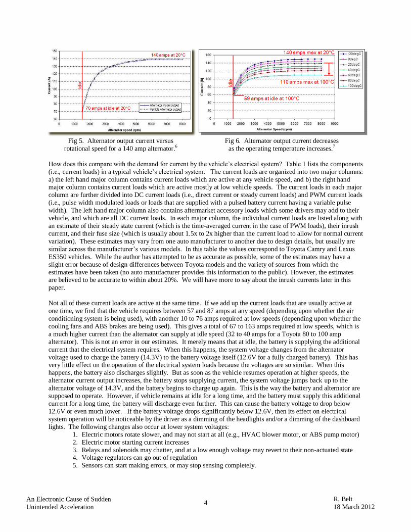
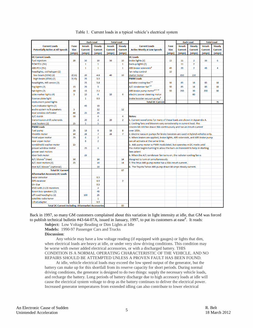
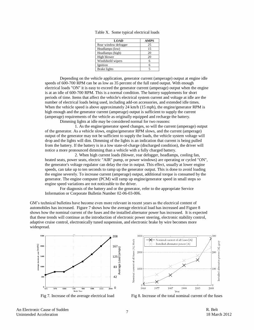
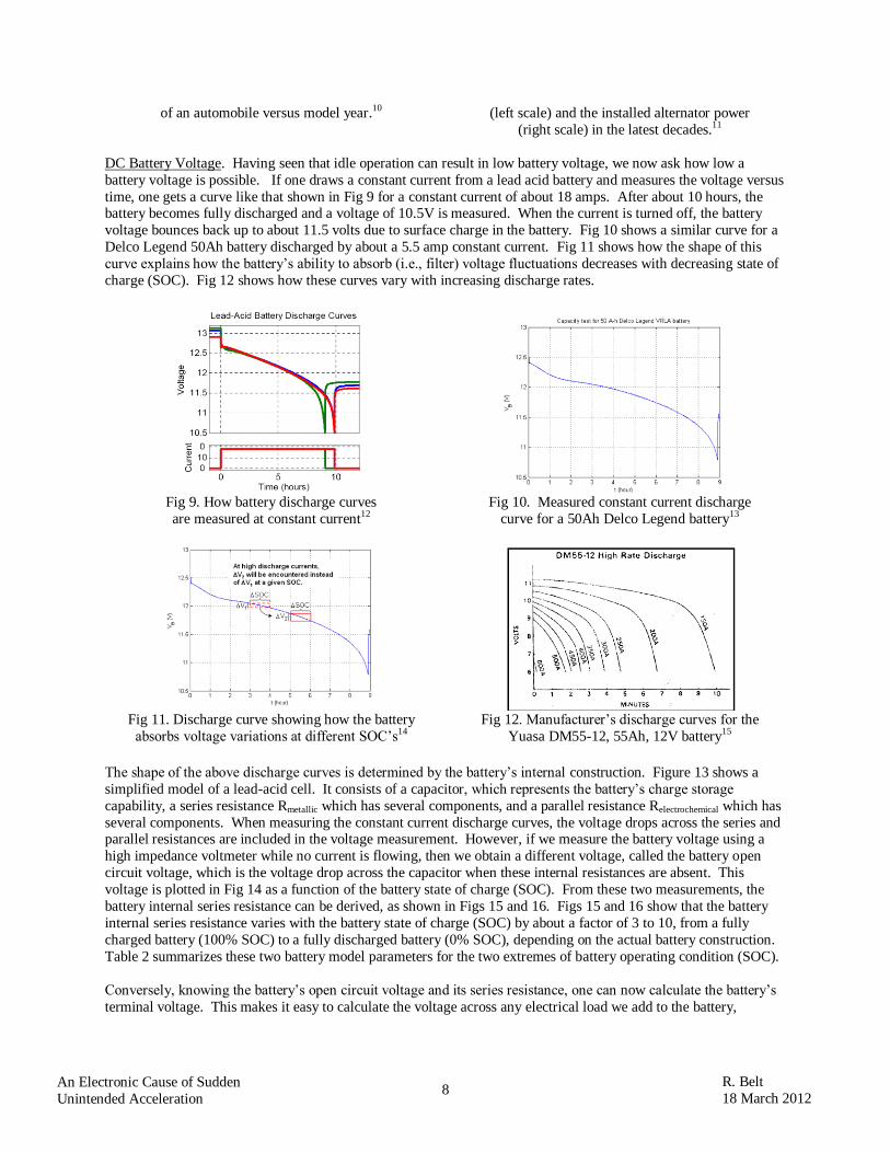
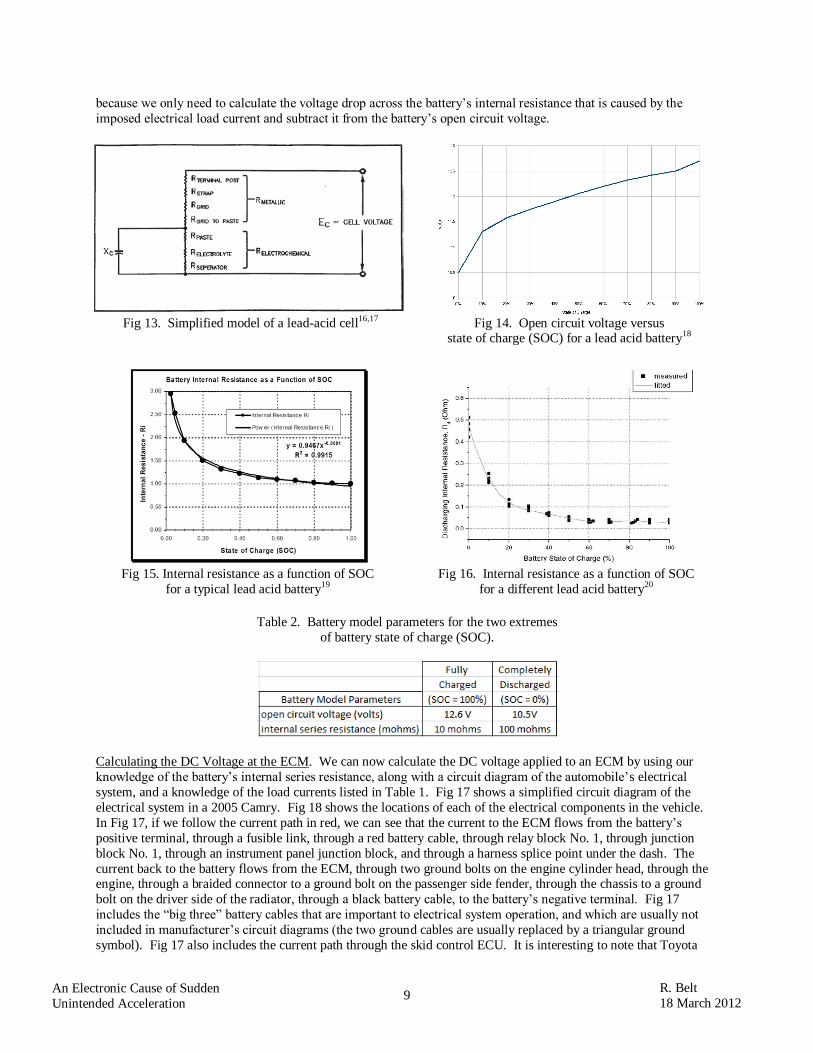
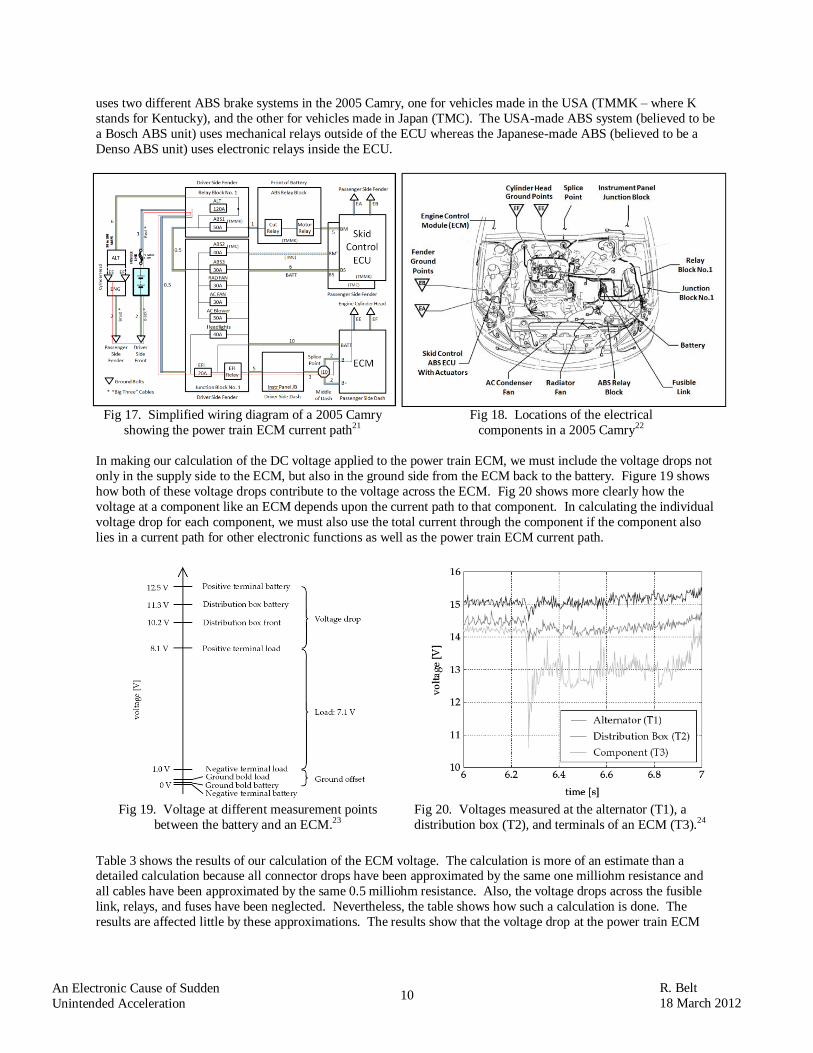
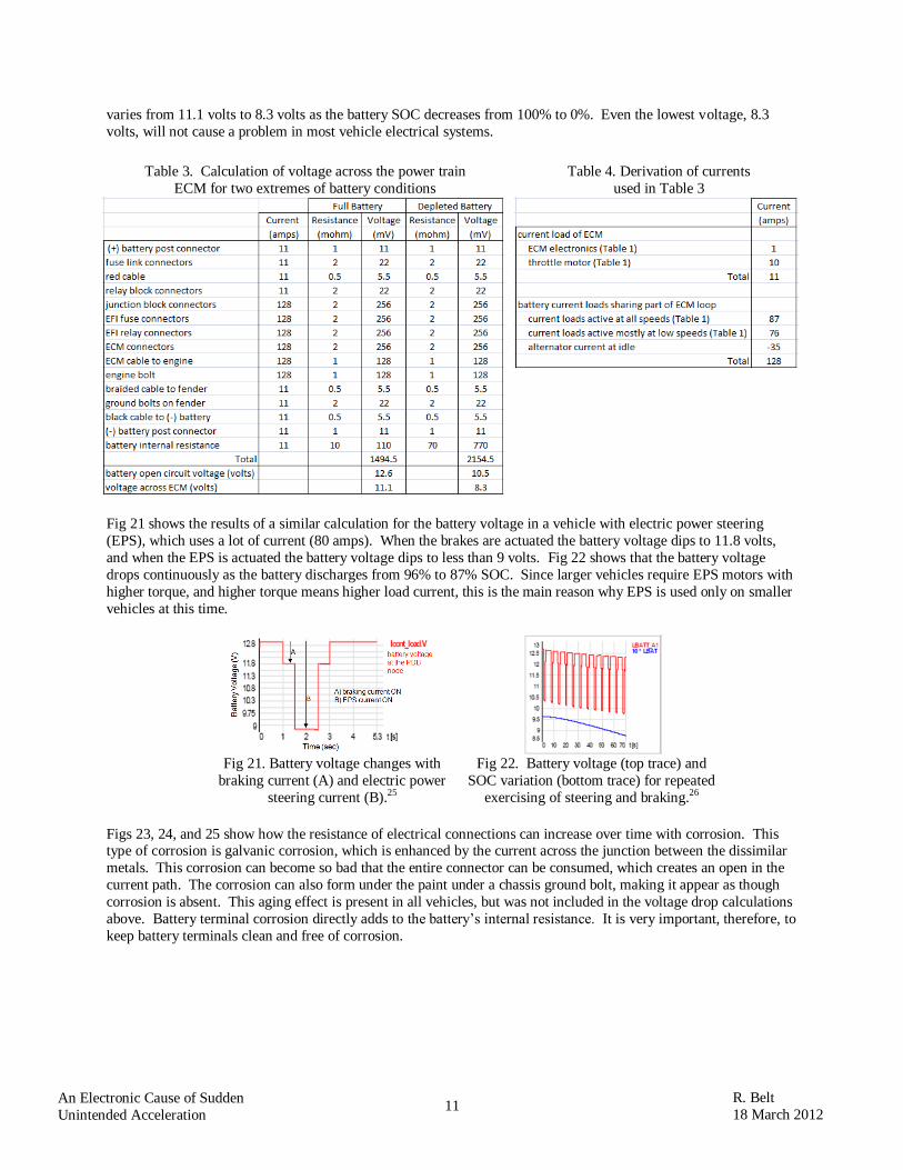
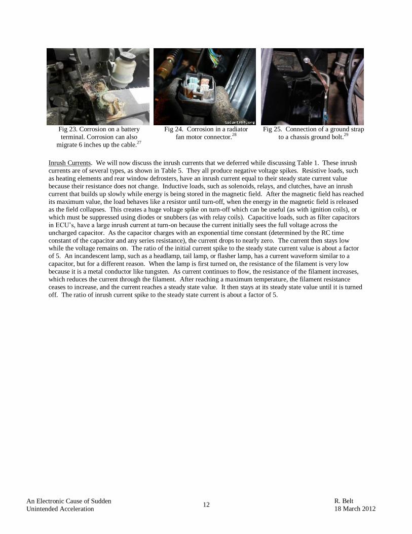
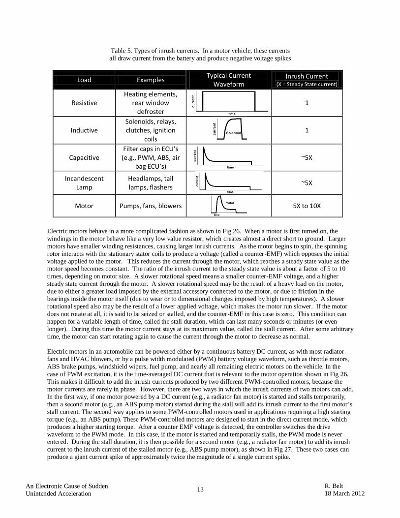
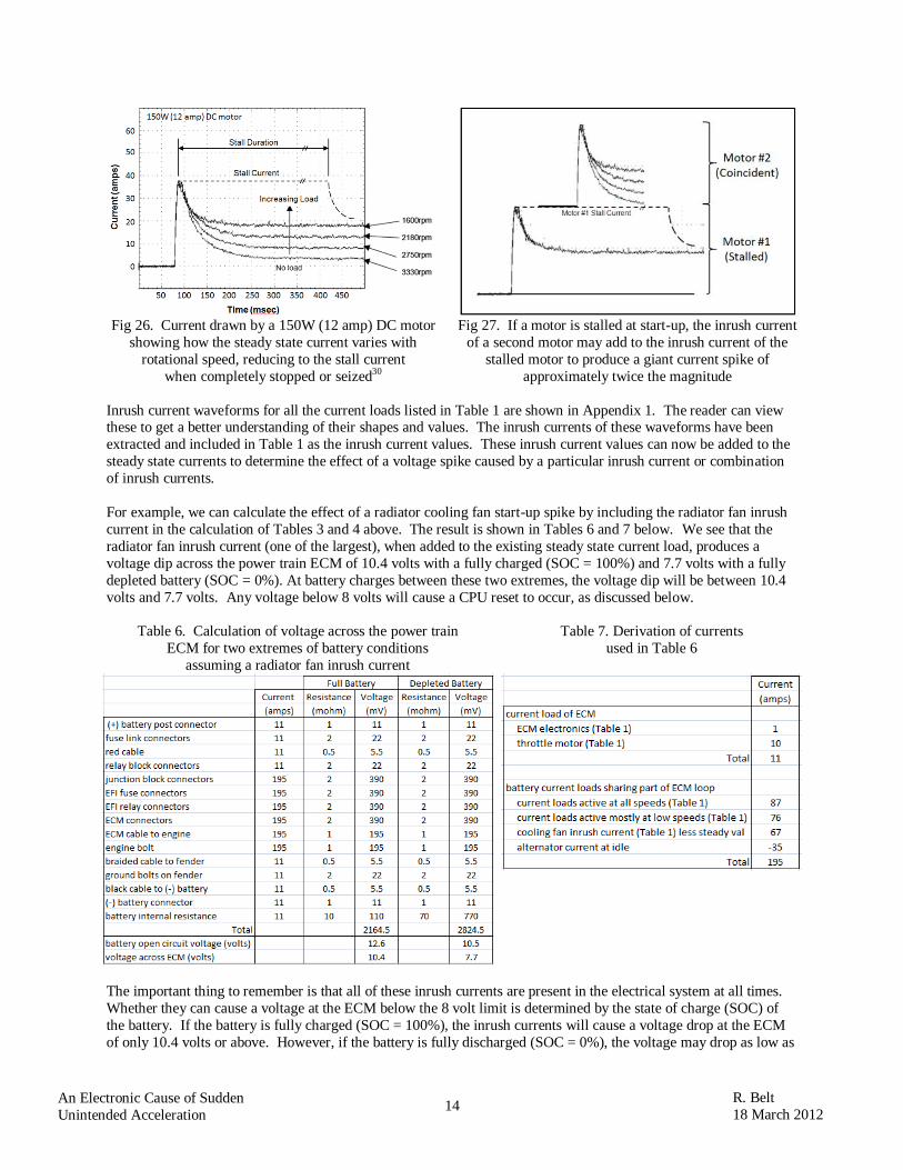
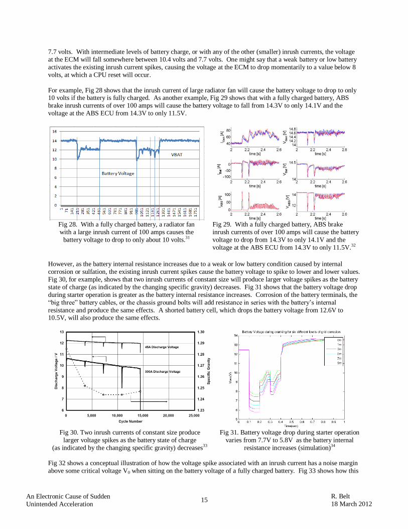
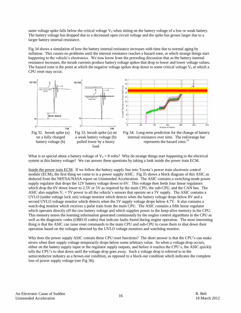
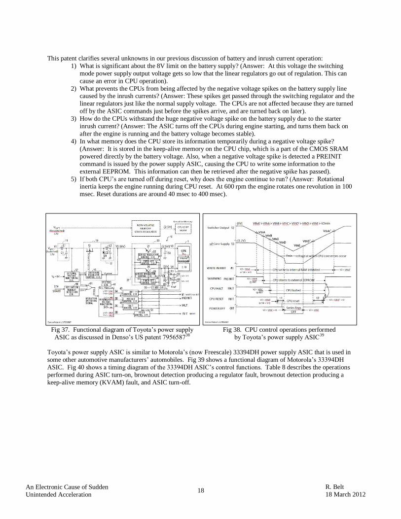
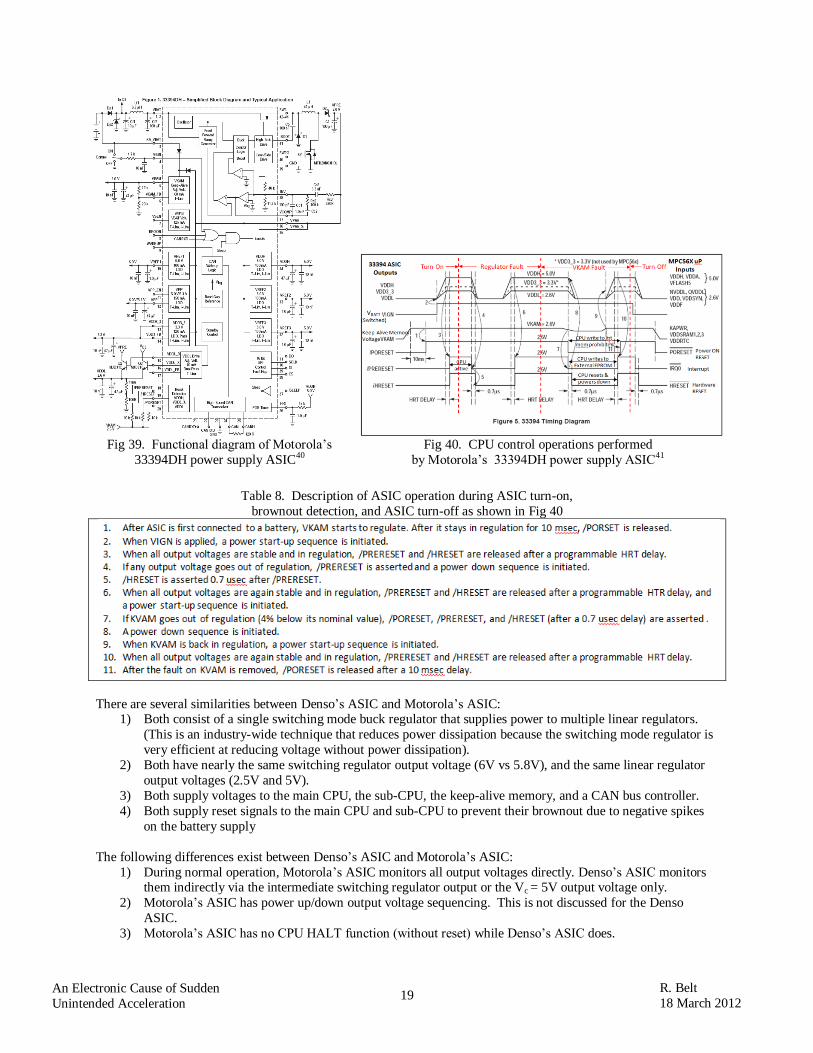
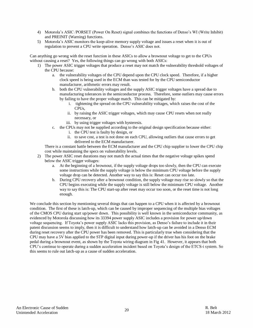
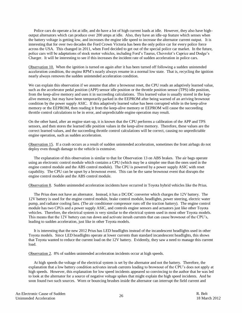
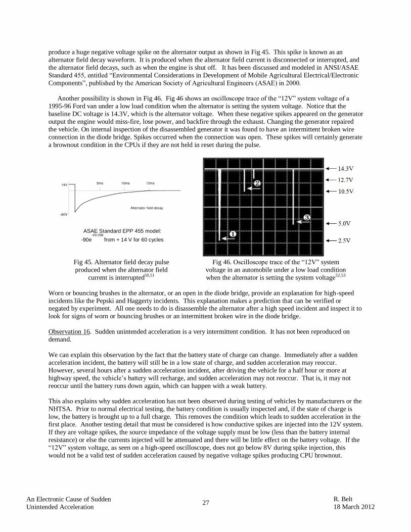
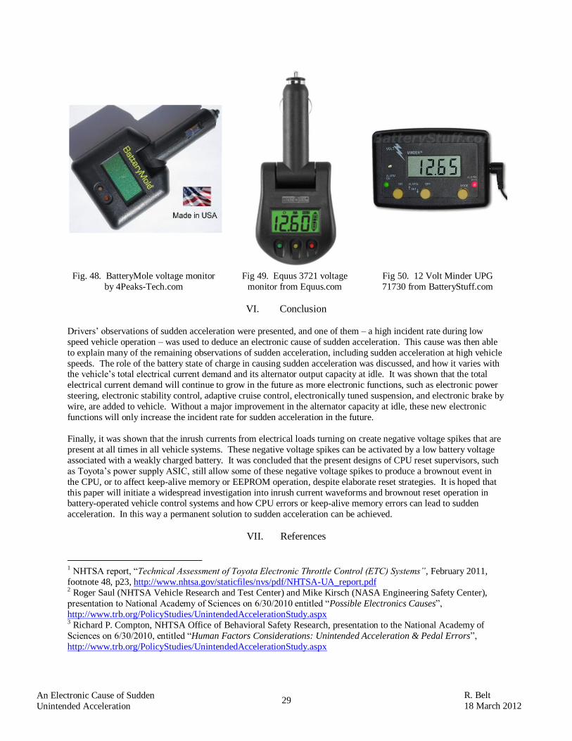

32
R Belt
18 March 2012 An Electronic Cause of Sudden
Unintended Acceleration