24 November 20111 CERL Portal Manuscripts and Early Printed Material.
EUSA-CERL TECHNICAL REPO N-88/
August 1988US Army Corpsof EngineersConstruction EngineeringResearch Laboratory
AD-A200 491
An Economic Assessment ofRenovating Temporary WoodFrame Buildings DTICby ELE'CTJPeter V. Schaeffer OCT 3 1 1988John J. FittipaldiPaul Armstrong
This research is intended to help installation Directorateof Engineering and Housing (DEH) personnel analyze theeconomic feasibility of renovating WWII era temporarywood frame buildings. A survey form and instruction guidewere developed to collect information on the physical con-dition and structural soundness of these buildings. Theform was used to evaluate WWII era buildings at four Armyinstallations. Rehabilitation and maintenance cost data wascollected at the four study sites. The major common prob-lems of renovation and/or current use were identified. Thisresearch indicated that renovation of WWII buildings is aneconomic alternative to new construction.
Approved for public release; distribution is unlimited.
88 1028 017

USER EVALUATION OF REPORT
REFERENCE: USA-CERL TR N-88/21, An Economic Assessment of henov)atingTemporary Wood ,rame Buildings
Please take a few minutes to answer the questions below, tear out this sheet, and returnit to USA-CERL. As a user of this report, your customer comments will provide U A -
CERL with information essential for improving future reports.
1. Does this report satisfy a need? (Comment on purpose, related project, or other areaof interest for which report will be used.)
2. How, specifically, is the report being used? (Information source, design data or pro-cedure, management procedure, source of ideas, etc.)
3. Has the information in this report led to any quantitative savings as far as man-hours/contract dollars saved, operating costs avoided, efficiencies achieved, etc.? If so,please elaborate.
4. What is your evaluation of this report in the following areas?
a. Presentation:
b. Completeness:
c. Easy to Understand:
d. Easy to Implement:
e. Adequate Reference Material:
f. Relates to Area of Interest:
g. Did the report meet your expectations?
h. Does the report raise unanswered auestiorq_

i. General Comments. (Indicate what you think should be changed to make this re-port and future reports of this type more responsive to your needs, more usable, improvereadability, etc.)
5. If you would like to be contacted by the personnel who prepared this report to raise
specific questions or discuss the topic, please fill in 'he following information.
Name:
Telephone Number:
Organization Address:
6. Please mail the completed form to:
Department of the ArmyCONSTRUCTION ENGINEERING RESEARCH LABORATORYATTN: CECER-IMTP.O. Box 4005Champaign, IL 61820-1305

UNCLASSIFIED,SECURITY CLASSIFICATION OF THIS PAGE
Form ApprovedREPORT DOCUMENTATION PAGE oM8 No 0704 0188Exp Date Jun30 1986
la REPORT SECURITY CLASSIFICATION lb RESTRICTIVE MARKINGSUnclassified
2a SECURITY CLASSIFICATION AUTHORITY 3 DISTRIBUTION /AVAILABILITY OF REPORT
Approved for public release; distributionZb DECLASSIFICATION 'DOWNGRADING SCHEDULE is unlimited.
4 PERFORMING ORGANIZATION REPORT NUMBER(S) S MONITORING ORGANIZATION REPORT NUMBER(S)USA-CERL TR N-88/21
6a NAME OF PERFORMING ORGANIZATION 6b OFFICE SYMBOL 7a NAME OF MONITORING ORGANIZATIONU.S. Army Construction Engr (If applicable)Resfc=cLt u, Laboratory CECER-EN
6c ADDRESS (City, State, and ZIPCode) 7b ADDRESS(Cty, State. and ZIP Code)
P.O. Box 4005Champaign, IL 61820-1305
8a NAME OF FUNDING/SPONSORING Bb OFFICE SYMBOL 9 PROCUREMENT INSTRUMENT IDENTIFICATION NUMBERORGANIZATION (If applicable) /
HQFORSCOM ICEN-CDP-M DACA 8 -00018c ADDRESS (City, State, and ZIP Code) 10 SOURCE OF/FUNDING NUMBERSFort McPherson, GA 30330 PROGRAM PROJECT TASK WORK UNIT
ELEMENT NO NO NO ACCESSION NO
11 tITLE (Include Security Classification)An Economic Assessment of Renovating Temporary Wood Frame Buildings (U)
12 PERSONAL AUTHOR(S)Schaeffer, Peter V.; Fittipaldi, John J.; Armstrong, Paul
13a TYPE OF REPORT 13b TIME COVERED 14 DATE OF REPORT (Year Month, Day) 15 PAGE COUNTfinal FROM _ _ TO 1988, August 69
16 SUPPLEMENTARY NOTAFIONCopies are available fron, the National Technical Information Service
Springfield. VA 2216117 COSATI CODES 18 SUBJECT TERMS (Continue on reverse if necessary and identify by block number)
F,ELD GROUP SUB-GROUP Buildings
Economic analysis
19 ABSTRACT (Continue on reverse if necessary and identify by block number)
This research is intended to help installation Directorate of Engineering and Hous-ing (DEH) personnel analyze the economic feasibility of renovating WWII era temporarywood frame buildings. A survey form and instruction guide were developed to collectinformation on the physical condition and structural soundness of these buildings. Theform was used to evaluate WWII era buildings at four Army installations. Rehabilitationand maintenance cost data was collected at the four study sites. The major commonproblems of renovation and/or current use were identified. This research indicated thatrenovation of WWII buildings is an economic alternative to new construction.
20 DISTRIBUTION AVAILABILITY OF ABSTRACT 21 ABSTRACT SECURITY CLASSFICATIONDNCL^KSIFEDIJNLMITF ] 'AMF AS OPT Ql DTIC USERS Unclassified
22a WE . IE INDIVIDUAL TEEPHONE(Include Area Code) 22r OFFICE SYMBOLN oria wIenle 7 352-6511 x 353 1 CECER-IMT
DO FORM 1473, 84 MAR 8 3 APR edition may be used untI exhausted ECiRiTy (LASSIFiCArION O: THIS P4(iAll other editions, are obsolete
UNCLASSIFIED
FOREWORD
This investigation was performed for the Master Planning Branch, Headquarters,Forces Command (HQFORSCOM). The Technical Monitor was Mr. James Carmody,FCEN-CDP-M. The U.S. Army Construction Engineering Research Laboratory (USA-CERL), under project number DACA 88-86-D-0001, "The Real Cost of WWII Wood FrameBuildings," engaged the services of the Department of Urban and Regional Planning atthe University of Illinois at Urbana-Champaign. Department personnel directly involvedin this research were: Peter V. Schaeffer, Assistant Professor of Planning; Paul Arm-strong, Assistant Professor of Architecture; and Teresa Almeda, Man-Hyung Lee, andPaul Webber, Research Assistants.
The personnel from USA-CERL, Environmental Division (EN) involved in the studywere John J. Fittipaldi, Principal Investigator, and Paul R. P. Skidmore, Research Assis-tant. Mr. Robert Neathammer of USA-CERL's Facility Systems Division reviewed pre-liminary drafts of this report. Dr. R. K. Jain is the Chief of USA-CERL-EN. The Tech-nical Editor was Gloria J. Wienke, Information Management Office.
COL Carl 0. Magnell is Commander and Director of USA-CERL, and Dr. L. R.Shaffer is Technical Director.
Act T ..,w _S_ _ -- "
fhTiS C', - ' 71
.1]~~~ ~~ t
" . .. . .. ...............
---. --- -- -
3

CONTENTS
Page
DD FORM 1473 1FOREWORD 3LIST OF TABLES AND FIGURES 5
INTRODUCTION ........................................................ 7BackgroundObjectiveApproachScope
2 DESCRIPTION OF STUDY SITES ......................................... 10Climatic and Environmental ConditionsInventory of WWII Era BuildingsDescription of WWII Era BuildingsPrevious Renovations of Barracks
3 SURVEY RESULTS ..................................................... 18Recent Building RenovationsExisting Building ConditionsCharacteristics of Renovated Buildings
4 COSTS OF RENOVATION ............................................... 27
5 OPERATION AND MAINTENANCE COSTS ................................ 30Operating CostsMaintenance Costs
6 ECONOMIC FEASIBILITY OF RENOVATION ............................... 32
7 CONCLUSIONS ........................................................ 34Economic Feasibility of RenovationPhysical ConditionCost DataProblems of Renovation and Use
8 RECOMMENDATIONS .................................................. 36
APPENDIX A: Building Evaluation Forms and Instructions 37APPENDIX B: Weather Data for Study Sites 49APPENDIX C: Tabulated Building Inspection Data 54
GLOSSARY 65DISTRIBUTION
4

TABLES
Number Page
I Current Use of WWII Era Wood Frame Buildings 112 Survey Sample TWBs by Current Use 18
3 Cost of Converting a Warehouse to AdministrativeUse at Fort Hood, TX
284 Rehabilitation of 14 Buildings at Fort Ord 29
5 Assumptions: Renovation of Typical WWII Era Barracks 33
Cl Year Built 54
C2 Building Size54
C3 Usage 55
C4 Type of Construction 55
C5 Foundation 56
C6 Exterior Finish 56
C7 Handicapped Access 56
C8 Insulation 57
C9 Capacity 57
CIO Structure 58
CII Exterior Siding 59
C12 Exterior Walls/Doors 60
C13 Interior Finish 61
C14 Plumbing 62
C15 Heating/Air Conditioning 63
C16 Electrical Components 64
C17 Miscellaneous Components 64
5

FIGURES
Number Page
1 Location of Study Sites 9
2 Barracks Floor Planb 12
3 Free-Standing Chimney of a Barracks at Fort Lewis 14
4 A Barracks at Fort Hood With the Chimney IncorporatedInto the Building 14
5 Open interior of a WWII Era Temporary Barracks 16
6 Dining Hall for Enlisted Personnel 16
7 Building Rehabilitation at Fort Lewis 19
8 Building Rehabilitation at Fort Hood 19
9 Building Rehabilitation at Fort Ord 20
10 Building Rehabilitation at Fort McCoy 20
11 A Window h Poor Condition 23
12 Signs of Water Damage to Structural Member of aTwo-Story Barracks 25
1.1 Fire Escapes 26
Al Temporary Wood Structure Assessment Form 38
A2 Building Components 40
A3 Foundations 45
A4 Wall Structures 46
A5 Roof Structures 46
A6 Floor Structures 47
A7 Window/Door Structures 47
AS Mechanical Systems 48
A9 The Electrical System 48
B1 Location of Fort Lewis, WA 49
B2 Location of Fort Hood, TX 50
B3 Location of Fort Ord, CA 51
B4 Location of Fort McCoy, WI 52
6
AN ECONOMIC ASSESSMENT OF RENOVATINGTEMPORARY WOOD FRAME BUILDINGS
1 INTRODUCTION
Background
The onset of World War II (WWII) required the rapid construction of wood framebuildings to satisfy the demand for barracks, administration buildings, maintenancebuildings, and warehouses. These buildings were considered "temporary," to be disposedof after the war ended. However, many of these WWII wood structures are still beingused today.
Congress has proposed that the Army remove the WWII era temporary wood framebuildings from its inventory as soon as possible unless their use is economically justi-fied. A preliminary target date was set for 1990. Reasons cited for the removal include:energy inefficiency, operational inefficiency, costly maintenance, and limited fire safe-ty.' However, Major General Norman G. Delbridge, Jr., Deputy Chief of Engineerssaid:
The facility inventory of the Army, which includes WWII tempo-rary buildings, is not adequate to support current and projectedmissions plus mobilization. The known construction requirementjust to support rapid mobilization is $2.9 billion. A legislativerequirement to tear down useful WWII facilities is unrealisticwit-n,,t re-'-"-.ment faiMit*es and wvould bc csunteeptoductiveand serve to increase the construction requirement needed formobilization. 2
In light of the Congressional proposal and the variety of policy attitudes toward thecontinued use of WWII temporary buildings, Headquarters, Forces Command (HQFORS-COM) asked the U.S. Army Construction Engineering Researcli ilabutatory (USA-CERL)to assess the role of these buildings and answer the following questions. Do these WWIIera buildings fulfill their current purposes adequately and economically? If not, can theybe improved to perform satisfactorily at a reasonable cost?
This project is one of a series dealing with WWII temporary wood buildings (TWBs).One project being conducted concurrently provides guidelines for evaluating the use ofthese buildings. 3 Another project developed an easy-to-use computer program thatprovides an accurate method of estimating repair and remodeling costs.'
'Military Construction Appropriations for 1985, Hearings Before a Subcommittee onAppropriations, House of Representatives, part 4, p 16, Tuesday, February 28, 1984.
2 Major General Norman G. Delbridge, Jr., (Ret.) Military Construction Authorization andAppropriation, FY 1983, p 309.
3 David Reed, et al., Evaluation and Guidelines for the Use of Temporary Wood Buildingsat U.S. Army Installations, Technical Report N-88/06/ADA194989 (U.S. Army Construc-tion Engineering Research Laboratory [USA-CERij, April 1988).
'Paul R. P. Skidmore and John J. Fittipaldi, WWII Era Building Demolition andRenovation Cost Estimator (ESTER) 1.0 User's Manual, Technical Report N-88/13 (USA-CERL, July 1988).
7

Objective
The objective of this research is to help Army installation Directorate of Engineer-ing and Housing (DEH) personnel analyze the economic feasibility of retaining and up-grading WWII era buildings at U.S. Army installations. The following project goals wereestablished to support the objective.
1. Develop and test a method to assess the physical condition and structural sound-
ness of WWII wood frame buildings,
2. Collect and assess rehabilitation and maintenance cost data, and
3. Determine the major common problems of renovation and/or current uses.
Approach
A form to gather information on the physical condition and structural soundness ofWWII wood frame buildings was developed. To ensure consistency in its use, a short in-struction guide was also written. (The form and guide are in Appendix A.)
The initial survey evaluated 28 buildings at 3 Army installations: Fort Lewis, WA;Fort Ord, CA; and Fort Hood, TX. Each installation has a large inventory of WWII erabuildings. These three study sites were selected because they represent a range ofenvironmental conditions and differing management and maintenance practices. Thebuildings were selected in collaboration with installation personnel to ensure represen-tation of the three major uses (barracks, administration, and warehous-ng/storage) and ofbuilding conditions. A random sample process was not feasible due to uncertainty aboutaccess to some buildings at the time of the site visits.
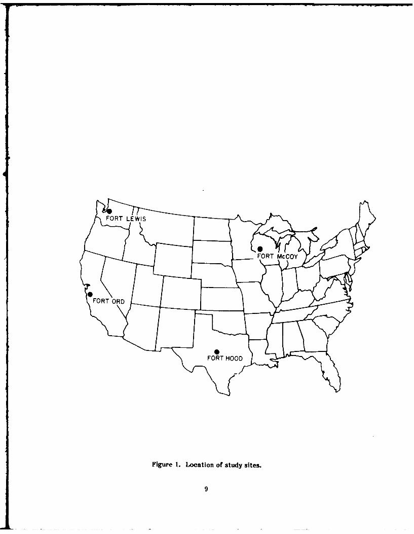
The initial evaluations took place during July and August 1986 and were successfulin obtaining information about the structural condition of WWII era wood frame build-ings. However, the approaches to dealing with these buildings were sufficiently differentamong the three bases to warrant a visit to another site. Fort McCoy, WI was chosenbecause almost all its buildings are WWII era wood frame structures and the installationis located in yet another climatic region. Fort McCoy also differs from the other ,iLal-lations in that it does not serve regular Army units but the National Guard and ArmyReserves. The evaluation of 20 buildings at Fort McCoy took place during January1987. Figure 1 shows the general location of the four installations.
The information obtained by inspecting these TWBs was verified and supplementedthrough interviews with DEH personnel. Additional information on maintenance proce-dures, recurring maintenance problems, rehabilitation costs, and operating and mainte-nance costs was requested.
The costs of alternatives were evaluated using economic analysis. Present valuesof investment alternatives were calculated to provide a basis for comparison.
Scope
The scope of this study precluded an investigation of all possible uses of WWII woodframe buildings. Three major uses were selected for investigation: barracks, administra-tion buildings, and warehouses. However, most of the findings can be generalized toother uses as well.
8
FORT McCOY
F O R T O R D , . . . .
FORT HOOD
Figure 1. Location of study sites.
9

2 DESCRIPTION OF STUDY SITES
Climatic and Environmental Conditions
Appendix B contains weather data for each study site. The data indicate that theweather at the study sites is not a major threat to wood structures. Preventive mainte-nance procedures should be sufficient to reduce major problems due to the climate.However, the weather at any site must be independently evaluated to determine how itaffects the building's condition and maintenance and repair efforts.
To assess the probability of a building decaying because of the climate, even whensimilar maintenance procedures are followed, R. C. DeGroot developed a climate decayindex for the United States.S According to DeGroot, three of the four study sites arelocated in regions where the climate decay index is in the medium range. Only Fort Ordis in a region with a low decay index.
Termite infestation poses another threat to wood structures. Forts Ord and Hoodare located in regions where the probability of subterranean termite infestation is highand Forts Lewis and McCoy are located in regions where the probability is slight tomoderate.I
The possibility of an earthquake reducing a structurally sound building to a pile ofrubble must also be considered. The effect of an earthquake ranges from no damage(Fort Hood), to minor damage (Fort McCoy), to major damage (Fort Lewis), and disaster(Fort Ord). However, WWII era temporary wood frame buildings generally suffer lessdamage than permanont construction.
Inventory of WWII Era Buildings
All four installations have a large number of WWII era wood frame buildings whichwere constructed between 1940 and 1946. Table I presents the current uses of thebuildings by major use categories. (The information for Fort McCoy was not available,except for the total number of wood frame buildings, and for the percentage that arebarracks.) It is immediately apparent that these buildings play only a small role in hous-ing enlisted men at Forts Hood and Ord. At Fort Hood, permanent troops are no longerhoused in temporary wood frame barracks. At Fort Ord, the same situation is antici-pated by about 1990. By e-ntrast, 315 WWII era barracks house permanent troops at FortLewis.
Description of WWII Era Buildings
In most cases, WWII wood frame buildings are overengineered. They have wood pilefoundations supported by concrete spread footings and contain large quantities of clear,full dimension wood that is tightgrained and knot free, indicating that only heartwood
sR. C. DeGroot, "An Assessment of Climate Index in Predicting Wood Decay in Houses,"Durability of Building Materials 1 (1982), pp 169-174.
bR. H. Beal, J. K. Mauldin, and S. C. Jones, "Subterranean Termites - Their Preventionand Control in Buildings," Home and Garden Bulletin 64 (U.S. Department ofAgriculture, Forest Service, 1983).
10

Table 1
Current Use of WWII Era Wood Frame Buildings
Use Fort Lewis Fort Hood Fort Ord Fort McCoy*No. % No. % No. % No. %
Enlist. Barracks 315 ?2.2 31 4.2 145 14.3 30.0Admin & Supply 168 11.9 27 3.6 1 0.1General Storehouse 156 11.0 44 5.9 136 13.4Admin - General 104 7.3 83 11.2 144 14.2Detached Day Room 101 7.1 2 0.3 26 2.6General Instruction 83 5.9 36 4.9 29 2.9Enlist. PersonnelDining 81 5.7 1 0.1 19 1.9
General PurposeStorage Shed 52 3.7 51 6.9 22 2.2
Vehicle MaintenanceShop 50 3.5 94 12.7 21 2.1Army Res.Center Bldg. 32 2.3 0 0 0 0Company Headquarters 18 1.3 4 0.5 60 5.9Battalion HQs 15 1.1 33 4.5 29 2.9Gen. Operations Bldg. 0 0 30 4.0 46 4.5Batt.Con.Arms Stor. 5 0.4 58 7.8 9 0.9Guest House 1 0.1 4 0.5 41 4.0Other 236 16.7 243 32.8 285 28.1
Total 1417 100.0 741 100.0 1013 100.0 1566 30.0
*Other information not available.
was used. Structural trusses and chords are often doubled. Columns are oversized fordesign loads and extra crossbracing is added to prevent racking and twisting. Floor joistsare substantial (typically 12 in. deep for a two-story barracks) and closely spaced. Large,clear wood beams distribute the building's weight to a grid of piers aligned 10 ft oncenter.
Barracks
The hallmark of WWII era buildings is their inherent simplicity and adaptability. Abarracks prototype was quickly developed and was only slightly modified at differentinstallations (see Figure 2 for floor plans). For instance, the mechanical room of bar-racks at Fort Lewis (containing an oil furnace, water heater, and electrical switchbox)was located on a slab-on-grade. An exterior duct vented the furnace in the mechanicalroom to a freestanding chimney approximately 8 ft from the building. A brick base rising10 to 15 ft from the ground supported a metal flue which was tied into the roof by metalbracing (Figure 3). Mechanical rooms at Fort Ord were in the center of the building andwere raised on piles to be even with the first floor (Figure 4). The freestanding chimneyswere eliminated. Although the latrines were typically located at one end of the barrackson a slab-on-grade foundation, some latrines at Fort Lewis had been housed in separateone-story slab-on-grade buildings located near the barracks.
11

Sl
Li
I.-
P- t- 2 * I'(
x 4,
2 IoT z C4
12

000-.
ID C0'0
N i cn
0 _ NN ij I Z
0 L)C-i CY
N NL CLJ
Wr L-U
v C4
zw 0 U0 LO N ()
y 001
0) w0 .1(
0-J
~w 8~
~0 W
-0E5
XI- F5
I~3 ~NU
0~0
Ln -;1<

- *1
Figure 3. Free-standing chimney of a barracks at Fort Lewis.
Figure 4. A barracks (being demolished) at Fort Hood with the chimney incorporatedinto the building.
14

The original interiors of WWII era barracks were open and unobstructed. Columngrids modulated spans and distributed loads evenly to supporting piers (Figure 5). Firstand second floor plans were very similar. Ductwork was located along the longitudinalaxis of the building. Interior wall surfaces were left unfinished with exposed studs andexterior sheathing. Wood double-hung windows were standard. Interior partition wallswere originally clad with boards. Electrical wiring was usually exposed.
Dining Halls
Dining halls have a more specialized function. In plan, dining halls at all installa-tions were uniform. All the buildings were one-story and raised on wood-pile founda-tions. A large open room, about two-thirds of the total building area, was dedicated totroop dining. The remaining area housed the kitchen facilities, including all food preoar-ation and food storage equipment, plumbing, ventilation, electrical circuit box, waterheater, and dishwasher. In most cases this room was partitioned, thereby creating asmall room in one corner. In several instances, this partition was removed to createmore space for the kitchen equipment. A space heater in the dining room provided heatduring cold weather. Typically, an overhang or covered passageway sheltered the en-trance. Health regulations require screens on all dining hall windows and doors. Behindthe building, directly outside the kitchen, was a concrete pad which served as a loadingarea for supplies and services (Figure 6). Because storage space was sometimes insuffi-cient, sheds were placed in this area.
Previous Renovations of Barracks
In the 1960's, the Army made an effort to renovate WWII wood buildings. Prioritywas given to troop barracks, dining halls, and administration buildings in that order.These renovations have been generically labeled "Bruckerization" in deference to thegeneral who issued the mandate to update the buildings, making them more inhabitableand functional.
The typical Bruckerized barracks at the survey sites had been partitioned into two-man rooms. Interior partition walls were constructed of 2 by 2 studs covered by 1/8-in.wallboard on each side. New electrical wiring and new light fixtures were installed.Exterior walls were insulated and covered with wallboard, new vinyl asbestos tile (VAT)flooring was laid, and finished ceilings were installed. Latrines were remodeled and insome cases were added to the second floors of some troop barracks. New lavatory andtoilet fixtures were installed where necessary, exposed plumbing was repaired or re-newed, and new concrete floor topping or terazzo tile was installed. Enameled steel orwater resistant wallboard was added to interior latrine walls. Operable windows in theshowers were replaced with fixed windows and a single exhaust fan was added. In manybarracks, the fan's capacity has proved insufficient to remove moisture buildup resultingin problems of peeling paint and decay. The shower walls were clad with ceramic tileand metal shower pans were installed to protect the wood structural members and sub-flooring. Failure to properly install shower pans at Fort Ord resulted in wood rot, mold,and decay in many troop barracks.
"Volarization" was a program instituted during the 1970's to renovate WWII erabuildings. (The term refers to the all-volunteer Army.) Volarization was intended to bean economical solution for updating troop barracks using inexpensive materials and labor.
15
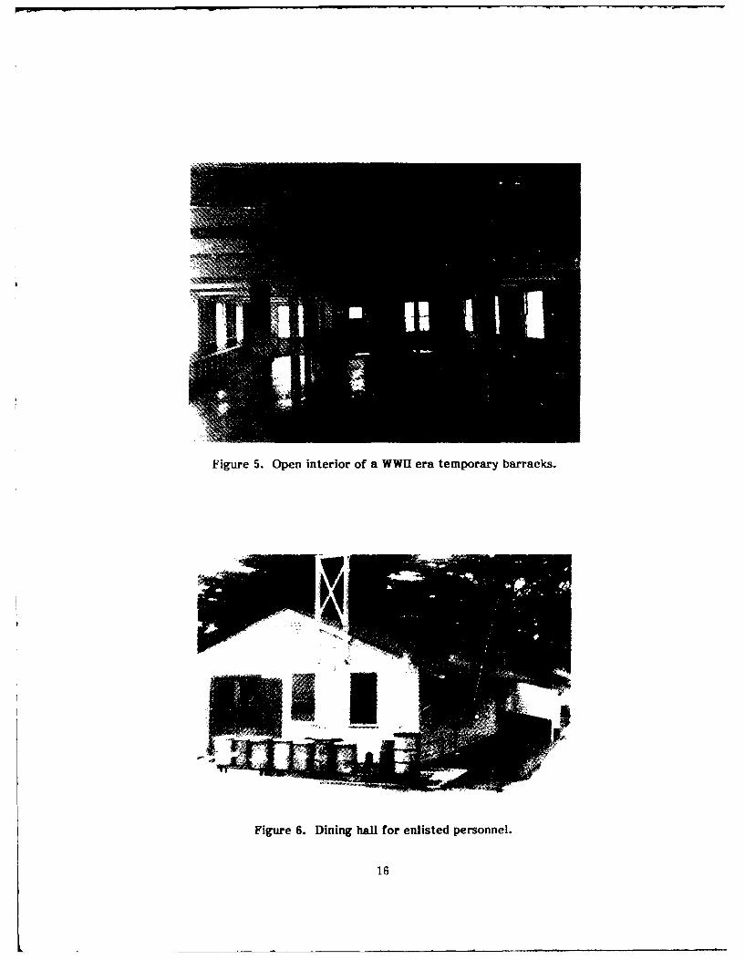
Figure 5. Open interior of a WWII era temporary barracks.
Figure 6. Dining hall for enlisted personnel.
16

Most of the renovations under these two programs were accomplished by trooplabor rather thun outnide ,ontructori. Tho docislon to s5bihtituto inexpnqive mt~rrinls inorder to rehabilitate the largest number of buildings for the dollar fell short of providinglonger term solutions toward upgrading troop barracks and making them relatively easyto maintain and able to withstand the normal day-to-day use. The Volarized buildings, inparticular, were characterized by cheapness. The materials have not performed wellover time and are easily damaged through normal use.
17

3 SURVEY RESULTS
The evaluation forni (Appendix A) used for inspecting the TWBs is organized bymajor building components: structure, exterior siding, exterior finishes, exterior windowsand doors, plumbing, HVAC, and electrical. Components are rated poor, average, orgood. A good rating was given only to components that performed as well as equivalentnew components. An average rating meant that the component performed its functionssatisfactorily, while a poor rating indicated deficiencies.
During the visits to Fort6 Lewis, Hood, and Ord, 28 buildings were carefully inspec-ted. Twenty buildings were inspected at Fort McCoy. The buildings were selected by theDEH to represent a variety of uses. Table 2 presents a summary of these buildings by usecategories.
Recent Building Renovations
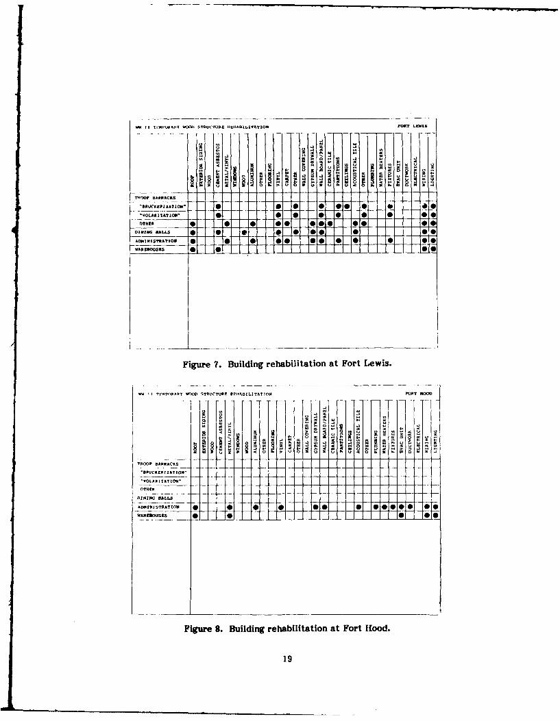
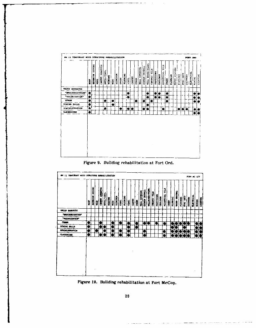
Each survey installation has prioritized its own needs regarding WWII wood buildingrehabilitation/renovation. Figures 7 through 10 show improvements rrn'1. at crach cf thefour survey installations.
Extensive rehabilitation of WWII TWBs has been undertaken at Fort Lewis. New in-terior partition walls were installed using 2 by 4 wood studs covered with either gypsumdrywall or 1/8-in. wood panel wallboard. New electrical wiring and new light fixtureswere installed. New VAT floor covering and finished ceilings (drywall or acoustical tile)were added. All exterior walls and attic spaces were insulated. Decayed or damagedbuilding components were replaced as required. In the latrines, new watertight cementtopping was laid, new lavatory and toilet fixtures installed (when required), wall-hunglavatory mountings were reinforced, and exposed plumbing was replaced as necessary.
Table 2
Survey Sample TWBs by Current Use
Current Use Fort Lewis Fort Hood Fort Ord Fort McCoy
General Storage 1 2 2Administration 1 3 2 9Enlisted Barracks 6 3 7General Instruction 1 1Detached Day Center IMess Hall 2 2 3Unknown 1 1
Total 13 5 10 20One-story 6 3 6 7Two-story 7 2 4 13
18
W I I MIPAHAY WOO STRUCTURE I4EIIA1O1LITATIOM FORT LKWIS
TROP BARRACKS
+0R. N 0 00 . . o
-- :. • I • •• •
-DIVINGjO BALLS. 01. 0I 0
_AMIITRTo - 0 0• 0 11 Isg0 Ag
TRO ARESCES A
Figure 7. Building rehabilitation at Fort Lewis.
1* 1 Tr"MpoA/ " -¢ 0 TAUCTrURF PEII1i51LIT/AT111 PORT HOOD
______~A 0 @00 00
0+ 0' No E. 8 a N
"BRUCRERIZATION" __
'VOLARIZATION'*_* 0OTHER * *
@0 0 0__0_ 0
WAREBOVSES ] 00
Figure 7. Building rehabilitation at Fort Lewis.
, , ((
+".,li+ a .-- o43 I ol l i I t
01iue8.Bidn reaiitto at Nor Hood. .
122U ~ Wl
J , 290
VW 11 TEMPORARY W0OD STROCTURE R NUbrLATRTrOU ranOR
O 3',4,A. MoI • I I• 44 - 3a,. p -3' 0io .3•,! .- Ma -* ' ' " " "" ' "'" "tROOP BARRACKS
0a-"81S 01o 1 1 0 0 I 0 0 _ 0DIVING HALLS * ___ 9
Figure 9. Building rehabilitation at Fort Ord.
VW II TIFRARY WOD STXIJIB aafWaLru2AI fa C
I ll i ii i ii.!i i: I Iii= MR
- 1.DOM A 0 0 0 1 9100 0 0
Figure 10. Building rehabilitation at Fort McCoy.
20

Water resistant wallboard was used throughout, except in the showers where ceramic tilewas installed and ventilation fans were added to remove the humid air. Renovated TWBswere retrofitted with new double-hung aluinum windows and resided with steel siding.New heating, ventilation, and air conditioning (HVAC) systems were added, including airconditioning in administration buildings. New ductwork and new plumbing lines wereInstalled throughout.
Of the four installations investigated, Fort Ord has done the least to rehabilitateits existing WWII era buildings. These buildings are still used to house troops, althoughsome of the barracks have been converted to administrative buildings. Several one-storybuildings have been moved from their original sites and a youth center was created byconnecting two WWII era TWBs.
Lighter structural framing seemed to be emaployed in the WWII wood buildings atFort Ord. This is probably attributable to the mild climate (snow loads are not a factor)and local building practice. However, this practice has caused problems after buildingrenovation when increased loading has been imposed upon the structural members due tofurnishings (e.g., computer equipment in offices), increased occupancies, and partitioningwhich surpass design criteria.
The interior walls of troop barracks at Fort Ord were covered with gypsum drywall,new electrical wiring and lighting fixtures were installed, and new heating units andductwork replaced the old HVAC system. The latrines were remodeled using water-resistant wallboard, ceramic tile, terrazzo tile flooring, and new plumbing fixtures.Exposed corroded sewer and water lines were replaced. Shower pans, neglected in theprevious renovations, were added. The barracks interiors remain open with moveablepartitions used as room dividers. All overhead ductwork was enclosed with gypsumdrywall and new ceiling tiles and VAT flooring were installed.
Compared to the other installations, Fort McCoy is unique since approximately 93percent of the buildings are still classified as temporary and have never undergoneBruckerization or Volarization. Projects have been undertaken on an as needed basis.Temporary renovations include adding room dividers or partitions (movable, freestanding, or stud wall), electrical outlets, ceiling lights, floor and wail covering, andpainting. This type of renovation is evident in some barracks that were temporarily usedfor special administrative purposes.
Permanent renovations were usually done in bachelor officer men's quarters(BOQs), bachelor enlisted men's quarters (BEQs), and administrative buildings. For thelatter, renovation included partitioning the si'owers and latrines into men's and women'srooms, adding a new heating system, new ceiling and lighting fixtures, floor covering,baseboards, and a handicapped access ramp, and painting.
Renovations of troop barracks to BOQs and BEQs generally consisted of adding newpermanent partitions, new plumbing (including new water and sewage lines and fixtures),electrical wiring, outlets and fixtures, and a new water heater and furnace. Exteriorwalls, the ground floor, and the attic were insulated, and new energy-efficient aluminumor vinyl-clad thermal windows were installed.
Existing Building Conditions
The following paragraphs summarize the findings at Forts Lewis, Hood, and Ord.Fort McCoy will be discussed separately, because, unlike the other three bases, it is not a
21
full-time military installation, and renovation and rehabilitation measures differed fromthose at the other study sites. Appendix C contains a complete tabulation of the surveyresults.
At Fort Ord, it was easiest to investigate the conditions of WWII era TWBs prior torenovation or rehabilitation. In over 90 percent of the buildings, the original wood sidingwas still intact. Successive exterior painting had color coded the buildings, makingdating of progressive renewals relatively easy. The original wood double-hung windowswere still in place. Damaged windows were routinely replaced with windows from othervacant WWII era TWBs.
In general, the WWII wood frame buildings at all the study sites were in good condi-tion, considering their age and, in many instances, the relatively modest investment intheir upkeep. As a result of the excellent quality of the wood construction and theoverengineering of the buildings, most buildings were structurally sound. Very few TWBswere torn down because of serious structural deficiencies. The major reason for demol-ishing WWII era wood structures at the initial three study sites was because they were inthe path of new construction.
Structural components that were considered in the inspections are foundation, ex-terior walls, roof, interior floors, and interior stairs. The most common type of foun-dation was spread footings/piles. Slab-on-grade foundations were also used. Some foun-dations were partly slab-on-grade and partly spread footing/piles. Nineteen foundationswere judged average and four were judged good. Five foundations could not be seen.Settling of buildings did not appear to pose any problems.
Exterior walls were more likely to receive a poor rating. This can be attributed inpart to the absence of eaves which left the siding vulnerable to water damage. Thisproblem occurred at all three initial study sites. The walls of 2 of the 13 buildings in-spected at Fort Lewis were in poor condition. Subsequent interviews with maintenancepersonnel also revealed that in some instances, entire walls had to be replaced as a resultof water damage. In spite of this, 18 walls were in average condition and 6 were in goodcondition.
Other structural components were generally rated average to good. Although nineroofs (four at Fort Lewis and five at Fort Ord) were rated poor, this rating only reflectsthat the roof cover needed to be replaced. No sagging or other indications of structuralproblems were observed. Similar findings hold for interior floors and stairs.
Exterior sidings were usually either the original wood sidings (particularly at FortOrd), or cement-asbestos shingles (particularly at Fort Lewis). Only at Fort Hood wasnew steel siding routinely installed on renovated buildings. Most sidings were in averagecondition.
Generally, the exterior finishes were rated average to good, although the exteriorpaint of five buildings was in poor condition. Four stairs/stoops were also in poor condi-tion and some of the fire escape stairs were only marginally adequate.
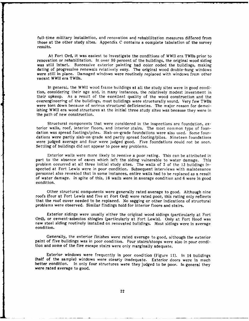
Exterior windows were frequcntly in poor condition (Figure 11). In 14 buildings(half of the sample) windows were clearly inadequate. Exterior doors were in muchbetter condition. In only four structures were they judged to be poor. In general theywere rated average to good.
22

Figure 11. A window in poor condition.
Interior finishes were also often in poor condition. While the wood or the concretefloors of the TWBs were rated average to good, floor coverings were deficient in eightbuildings. Similar results were obtained with respect to the wall coverings and parti-tions. Damaged partitions were observed frequently in Volarized barracks. In five build-ings, the ceilings were poor, and in six buildings, the paint condition was below average.The paint condition was a partieilar problem at Fort Lewis. Maintenance personnel com-plained that preparation of the paint surface by outside contractors was not alwayssatisfactory.
Given the age of the buildings, it is not uncommon to expect plumbing problems.Unfortunately, most of the plumbing is hidden away in floors and walls. It was, there-fore, not possible to gain reliable information. In general, water and sewer lines thathave not been replaced should he rated poor. Water heaters, tixtures, toilets, lavatories,and showers seemed to be in average to good condition.
The HVAC systems were in working order in all inspected buildings. Barracksusually did not have air conditioning and the furnaces were the original ones. While theyseemed to be working fine, most units were rated average because of their age. Accessto the utility room in some buildings was not possible. The ductwork was rated averageto good in most cases. Overall, the HVAC system is prooably adequate but does notdeserve a good rating except were it has been completely replaced.
23

Finally, the electrical systems (lighting, wiring, switches, and service panels) wereinspected. In general, the lighting and wiring had been updated over the years. Thelighting was rated good in 18 of the 28 buildings, the wiring was judged good in 11 build-ings, and switches and service panels were good in 8 buildings.
Generally, the TWBs at Fort McCoy were in good condition. One troop barrackswas still in the original condition. No renovation had been undertaken and only minorsigns of decay were detected.
Most foundations were spread footings. The footings were enclosed by perimeterwooden skirtings which were added after construction of the buildings. Minor dry rotproblems were evident in some of the skirting.
The roofs, including the asphalt tiles and roof joists, were in good condition. Mostof the roofing has been replaced and is routinely inspected for leaks and damage. Theexterior walls of most buildings were covered with cement asbestos shingles and were inaverage condition.
Doors and windows were generally rated average to good. Most of the inspectedbuildings still had the original components. Minor damage such as peeling paint or brokenglass is easily repaired and poses no problem.
The interior finishes differed substantially among the various building classifica-tions. Renovated barracks had painted interior walls, while administration buildings,mess halls, and class rooms had vinyl wall covering. Movable partitions were widely usedin offices. The interior finishes were in average to good condition.
Fort McCoy differs from the other three study sites in that most plumbing lines areexposed. Consequently, leaks are detected early and repairs are simple. In some of therenovated buildings, the plumbing lines have been enclosed within the walls. Waterheaters, fixtures, toilets, lavatories, and showers were rated average to good.
The electrical systems in renovated buildings at Fort McCoy were rated good. Thelight fixtures in most of these buildings had been replaced and new conduits and wiringhad been installed. Some troop barracks still had the original features. They were wellmaintained and safe and were rated average.
The HVAC systems were generally in good working condition. Heating systemsvary considerably. The fuels used by the different systems are coal, oil, wood pellets,and gas. The latter was generally limited to "permanent" buildings.
Characteristics of Renovated Buildings
Renovations of WWII era vood frame buildings have been successful in the sensethat they extended the useful life of the buildings and provided improved space or spacefor new uses. It is a tribute to the soundness of the materials and construction, as wellas the flexibility permitted by the design, that these adaptions have yielded space thatcan be ranked average to good.
In spite of the positive impression of the renovated buildings, some obvious prob-lems were noted. For barracks, the cost of renovation was usually kept in the range from$15 to $25/sq ft. This investment was not sufficient to upgrade all the major buildingservices: plumbing, HVAC system, and electrical systems. Although the electrical
24

system was usually upgraded or replaced to meet modern standards, the plumbing andHVAC systems were only repaired as needed. This has lead to recurrent plumbing andHVAC problems which diminish the value of the impr(uved space and create additionalmaintenance and operating costs.
The failure to completely replace the plumbing has resulted in problems with smallleaks, requiring relatively frequent find-and-fix repairs. If leaks go undetected, which islikely where pipes are inaccessible (in walls or floor), continued exposure to moisture willdamage the wood and may reduce the structural integrity of a building (see Figure 12).
Partitions were added during barracks renovations to create private space. Thishas resulted in a number of problems. First, the original duct system is not able tohandle return air. This shortcoming has been dealt with by directing return air into thecorridor through openings in the doors or walls. In case of a fire, this could cause smoketo accumulate in the corridor, barring the easiest escape route. Second, the original ductsystem does not perform satisfactcrily in distributing heat to the rooms. Complaintsabout too much or too little heat were frequently voiced by building users. The repairrecords also show many calls because of the heating system. On several occasions,placing the thermostat on the wall to the boiler room added to the unsatisfactory per-formance of the heating system. The solution to these problems would be to either re-place the originai diuetwork, or extend it so heat is properly distributed.
Most of the lurnaces were original equipment. While they generated sufficientheat, modern equipment would be considerably more efficient. Also, the reliability ofthese units is likel to decrease with age. The furnaces should be replaced in a renova-tion aimed at bringing WWII era TWBs up to modern standards.
Figure 12. Signs of water damage to structural member of a two-story barracks.
25
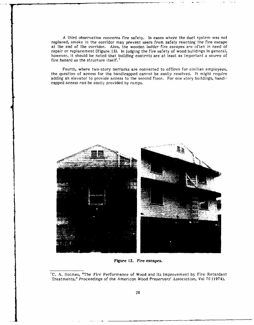
A third observation concerns fire safety. In cases where the duct system was notreplaced, smoke in the corridor may prevent users from safely reaching the fire escapeat the end of the corridor. Also, the wooden ladder fire escapes a'e often in need ofrepair or replacement (Figure 13). In judging the fire safety of wood buildings in general,however, it should be noted that building contents are at least as important a source offire hazard as the structure itself. 7
Fourth, where two-story barracks are converted to offices for civilian employees,the question of access for the handicapped cannot be easily resolved. It might requireadding an elevator to provide access to the second floor. For one story buildings, handi-capped access can be easily provided by ramps.
Figure 13. Fire escapes.
7 C. A. Holmes, "The Fire Performance of Wood and Its Improvement by Fire-Retardant
Treatments," Proceedings of the American Wood Preservers' Association, Vol 70 (1974).
26

4 COSTS OF RENOVATION
Average renovation and rehabilitation costs for barracks at Fort Lewis, Hood, andOtd, were $15 to $25/sq ft. Similar figures were mentioned for rehabilitation of admin-istration buildings, although the range was greater. Some variations between installa-tions, and even among buildings on the same installation, can be attributed to building-specific problems or to the extent of changes. At Fort McCoy, the average costs wereslightly higher ($25 to $28), but some of the renovations were more extensive than at theother three study sites. Generally, costs were low compared to new construction. It isnot possible, however, to directly compare the renovated buildings to new buildings. Newconstruction will not be wood, and will not be the same size, floorplan, and components.A comparison, therefore, requires two steps. First, a qualitative assessment of therenovated buildings is necessary. Do they achieve the same standards as new buildings?Second, what is the operating cost (e.g., energy cost) of a renovated building, what is themaintenance cost to keep the building in good condition, and how do these costs compareto a new building containing state-of-the-art technology and materials?
The cost per square foot of most TWB renovations at all four study sites rangesfrom $15 to $28. This range applies to barracks and administration buildings containing4,720 sq ft. One exception was found at Fort Lewis, where the most expensive troopbarracks-to-administrative use conversion (euphemistically referred to as the Taj Mahal)was contracted for an estimated $40/sq ft. In addition to replacing decayed, or damagedcomponents, the following changes were made:
* interior partitions (2 by 4 wall studs, gypsum drywall, and wood panel
wainscoting)
* wall-to-wall carpeting
" electrical wiring and fixtures
" suspended acoustical ceilings
" exterior wall insulation
e thermal pane double-hung aluminum windows
" coated metal siding
" fire escape stairs, smoke detectors, and sprinkler system.
In 1979, two TWB enlisted personnel mess halls at Fort McCoy were joined at a costof about $23,000 in current dollars. The additional work for renovation was done foranother $201,000 in current dollars. The renovated mess hall has an area of 5,483 squarefeet. The cost per square foot of this renovation (including some repairs in 1980) wasbetween $40 and $45 (current dollars).
A very successful conversion/adaptive reuse of a WWII era warehouse was observedat Fort Hood. The 12,427-sq ft building, constructed in 1942, was built to withstand veryheavy loads. This construction is ideal for conversion to office use because it virtuallyguarantees that the load capacity is sufficient for heavy furniture and substantialamounts of computer equipment. The conversion included additional services, moveablepartitions, and new windows, doors, and steel siding. The cost of this conversion was lessthan $13/sq ft. Table 3 provides a summary of the major costs for this rehabilitation.
27

Table 3
Cost or Converting a Warehouse to Administrative Use at Fort flood, TX
Item Labor Cost Material Cost Total Cost
Demolition $11,309 $746 $12,055Site Work 5,267 5,697 10,964Concrete 2,210 1,052 3,262Metals 6,469 7,134 13,603Carpentry 19,413 19,728 39,141Thermal and Moisture
Protection 4,016 6,713 10,729Doors and Windows 5,764 11,732 17,496Finishes 15,781 26,117 41,898Specialties 1,074 3,818 4,892
TOTAL $71,703 $82,737 $154,040
Rehabilitation of an enlisted men's WWII era TWB barracks for administrative usewas undertaken at Fort McCoy. The cost in current dollars was about $81,000 for this5,455-sq ft building, or approximately $15/sq ft. Additions and changes are as follows:
" exterior wall, floor, and attic insulation
" interior partitions and walls (drywall with veneer coat plaster)
* suspended acoustical ceilings
* windows
* heating unit.
At Fort Lewis, temporary wood buildings were renovated at a cost of approxi-mately $20/sq ft. It is possible to keep costs quite low as evidenced by the rehabilitationof 14 buildings at Fort Ord. A summary of the rehabilitation cost of those buildings isprovided by Table 4. The very low cost ($3.10/sq ft) of rehabilitation at Fort Ord isremarkable. However, these rehabilitations did not replace either the plumbing or theHVAC system. Only faulty parts in these two systems were replaced. Doors and win-dows were replaced only as needed, and replacement windows were "cannibalized" fromunused TWBs on the base. The buildings function satisfactorily, but do not achievemodern standards of comfort and privacy. Measured by the expenditure, however, thereturn on the investment is high.
28

Table 4
Rehabilitation of 14 Buildings at Fort Ord
Item Total Cost
Demolition $52,952Carpentry 10,655Doors and Windows 11,311Shower and Latrines
(Fixtures, Materials) 12,835Mechanical 63,199Electrical 5,685Finishes 47,894
TOTAL $204,531
Total Area: 66,080 sq ftCost per Square Foot: $3.10
29

5 OPERATION AND MAINTENANCE COSTS
Operating Costs
Operating costs consist of two major elements. One element is the expenditure forutilities: heating/air conditioning, water, and power. The water and power consumptionshould be the same for each use regardless of the type of building. Thus, in comparingmodern construction to renovated WWII wood frame buildings, it can be assumed thatexpenditures on these two utilities are the same. Differences occur in the cost of heat-ing and/or cooling. Certainly one would expect higher costs (per square foot) in WWII erabuildings that have not been insulated and where the original furnace was not replaced.If the HVAC system has been replaced, the cost relative to building size should be aboutthe same as for a newly constructed building.
The utility costs are dominated by the heating cost, followed by the cost of elec-tricity.8 Together they account for approximately 90 percent of the total utility costs.A survey at Fort McCo found the typical heating cost (including hot water) for a 5,310sq ft TWB barracks to be about $2,500 for FY85, based on an average occupancy rate of78 percent. For an administration building of the same size, this cost was $3,500, and fcra 1,800 sq ft classroom, the estimated cost was $2,000.
The second major element of operating costs is the efficiency of the building for aparticular use. A new building can be designed to fit the needs of a particular use, butrenovated buildings are less flcxible in that some major characteristics of the buildingare already determined. This may result in less efficiency for a given use than if a newbuilding were constructed. It is not possible to answer the question to what extent thiscould be a problem without reference to specific uses. However, the WWII era temporarywood buildings are very easily modified. Their open floor plan affords great flexibility inarranging the space to fit different uses. It is even possible to move buildings to anothersite, to join individual buildings together (as done at Fort Ord), or to extend an existingstructure (as done at Fort Lewis). The buildings can be adapted to fit most requirementswith minimal inconvenience and loss of efficiency for the users.
Maintenance Costs
One advantage of WWII temporary wood buildings is their simplicity. The compo-nents and systems are easily understood by maintenance personnel and are standardized,so parts are interchangeable. Buildings that have deteriorated beyond repair or are inthe path of new construction can be "cannibalized" for parts. This simplicity and stand-ardization makes them inexpensive to repair, as exemplified by the fact that deterio-rated siding on a two-story barracks can be replaced at a cost of only $8,000 to $10,000.
These buildings are also easy to repair. Working with wood does not require anyunique tools. Damaged wood walls are inexpensive to repair. Repairing damaged ma-sonry or concrete is not only more expensive, but the repair may not be able to restorethe original appearance. In wood buildings, it is relatively inexpensive to remove aninside wall cover to gain access to plumbing or wiring. This is often not the case withbuildings constructed of other materials. Also, the building components have standard
8Facilities Engineering and Housing: Annual Summary of Operations. Volume I - Exec-utive Summary (Department of the Army, 1984).
30

dimensions so emergency replacement parts can be found in local hardware stores. Somenewer buildings do not have these advantages. For example, odd door or windowdimensions have caused problems when components were damaged beyond repair. Notonly did the replacements have to be specially ordered, but they were also more expen-sive than standard size components.
The renovations kept these buildings simple. The only instance where changesrequired new skills or tools is the installation of steel siding. When siding is damaged,special tools are necessary to make the repairs. Initially at least, these tools were notavailable at the study sites.
Relatively detailed information about maintenance and repair costs was availableat Fort McCoy. For a sample of five BEQs and BOQs, the cost per square foot for FY85was slightly below $1. These costs, however, include some interior painting. In otheryears, these costs would be expected to be lower.
The M&R cost for two mess halls was approximately $1.60/sq ft for FY85. Thisfigure includes some major repairs of the kitchen facilities. For two classrooms (1,800 sqft each), the cost was about $0.11/sq ft.
There are no indications that maintenance expenditures of wood frame buildingsare inherently higher than those in structures made of other materials.
31

6 ECONOMIC FEASIBILITY OF RENOVATION
An accurate study of the economic feasibility of renovating TWBs depends on theintended use. A rough calculation of the economic feasibility of renovating a typical4,720-sq ft WWII TWB barracks to be continued to be used as a barracks is given as anexample. The cost of renovation will be compared to the cost of new construction. TheFY86 cost estimate of $55 sq ft for a barracks without dining will be used.
To present this calculation, several assumptions are made. First, to arrive at a topdollar amount, assume that the WWII barracks are renovated more extensively than ispresently the case. Since the range of renovation costs is $15 to $28, it is assumed thatfor $40/sq ft all services can be replaced or renewed to meet the same standards as thoseof a new building. Second, assume that after 10 years, $20,000 is needed to repair therenovated building, and that it then lasts another 10 years before additional resourceswould be needed. Also assume that a new building would need a major overhaul onlyafter 20 years. Finally, assume that both new and renovated buildings have the sameoperating and maintenance costs. The interest rate for discounting purposes is set at 10percent per annum.
These assumptions probably overstate the costs of the renovated WWII barracks.However, they are not entirely unrealistic. Under these assumptions, the present valueof the cost of the renovated barracks (without maintenance and operating cost) is$198,000. This is lower than the $260,000 cost to construct 4,720 sq ft of new barracksspace (at $55/sq ft). Under the assumptions listed previously, the cost of renovation is$62,000 less than the cost of new construction. From a diffcerent perspective, if a reno-vated barracks was more expensive to operate and maintain than a new barracks, over$7,000 more per year could be spent on the renovated barracks before the present valueof its total cost would equal that of a new barracks. This simple example suggests thatrenovation of WWII could be an economical alternative to constructing new barracks.Similar conclusions also apply to other kinds of uses.
Realistic cost figures of renovations undertaken at the first three study sites aresummarized in Table 5. The cumulative present value per square foot is quite low at justover $22 sq ft. Assuming that a new building would cost about $55/sq ft, and that therewould be no major repairs during the first 20 years of that new building's life, the dataindicate that any potential disadvantages of WWII era barracks would be compensated forby significantly lower costs. This sugge~s~ that WWHi TWBs can be renovated economi-cally.
To explore the example that is summarized in Table 5 further, assume that thebuilding cost would be $55/sq ft and that major repairs would occur at the intervals andfor the amount listed in the table. Under these assumptions, which favor the existingbuilding, the cumulative net discounted cost of the new building would be $295,690, orless than $56/sq ft. This illustrates that the repairs have only a minor impact on theresults of the analysis. The initial cost of renovation or of new construction, is thedeciding factor.
In this example, the cost difference between new construction and renovation islarge enough that significant changes in the assumptions would not alter the result.Renovation of troop barracks is likely to be economical even if the cost per square footis increasc. to ottain -. top dollar amount. The conversion of troop barracks to admini-strative uses also appears to be economical.
32

Table 5
Assumptions: Renovation of Typical WWH Era Barracks
Item Initial Cost Frequency of Cost of Major(Renovation Cost) Major Repairs Repairs
Demolition $9,100Carpentry 5,000 5 Years #500.00Floor Tile 6,500 5 Years 250.00
10 Years 6,500.00
Dry Wall 10,100 5 Years 1,000.00Windows 2,600 5 Years 250.00Insulation 3,200Metal Doors 500 5 Years 250.00
10 Years 500.00Metal Siding 6,100 5 Years 250.00Tile Work 2,700 5 Years 250.00Painting 5,000 5 Years 5,000.00HVAC 15,100 10 Years 1,000.00Plumbing 15,000 10 Years 1,000.00Electric 29,200 10 Years 1,000.00Total InitialCost $110,100
Other Assumptions: Building Size = 5310 square feet
Discount Rate = 10 per cent per annum
Life Time = 20 Years (until otherwise stated in Table 5)
Starting Year = 1987
Ending Year = 2006
Results: Cumulative Net Discounted Value = $117,689Cumulative Net Discounted Value Per Square Foot = $22.16
Because there is insufficient hard evidence regarding renovating enlisted personneldining facilities, it is desirable to study mess hall renovation in greater depth. Since thekitchens in the original mess halls are clearly too small, simple renovations may notresult in solutions that are comparable to new construction. It may be necessary to jointwo mess halls together, as done at Fort McCoy, or to expand an existing mess hall, asdone at Fort Lewis, to overcome this problem.
33

7 CONCLUSIONS
Economic Feasibility of Renovation
Renovation of WWII TWBs is a likely economical alternative to constructing newbuildings. However, an accurate study of the economic feasibility of renovating TWBsdepends on the intended use. Repair costs have only a minor impact on the outcome ofeconomic analysis. The initial cost of renovation versus new construction is the decidingfactor in determining the feasibility of renovation.
Physical Condition
Based on the physical condition surveys at Forts Lewis, Hood, and Ord, the WWIIwood frame buildings were structurally sound and in good condition considering their ageand the relatively modest investment in their upkeep. Exterior walls and windows arefrequently in poor condition. Interior finishes are also in poor condition. Because of theage of the buildings, plumbing which had not been replaced was in poor condition. Theelectrical systems, which had been updated over the years, were in good condition andthe HVAC systems were in working order.
The TWBs at Fort McCoy were in good condition. Most of the roofing had beenreplaced and the roof components were in good condition. The doors and windows werein average to good condition. Because the plumbing is exposed, leaks are detected andrepaired early. The plumbing is in average to good condition. The electrical systemswere rated good and the HVAC systems were in good working order.
Since most of the components in poor condition would have to be repaired or re-placed in a complete renovation, they have little impact on the economic feasibility ofrenovation.
Cost Data
The experience of the four study sites suggests that structurally sound TWBs can berenovated at an average cost ($15 to $28/sq ft) that is competitive with that of newconstruction. This is particularly true if the objective is to provide temporary space, inwhich case the building standards can be lower than for permanent space. However, itmust be noted that unless building services are also upgraded and/or replaced, the reno-vated structures cannot achieve modern standards of comfort and efficiency. Thus,while the investments yielded a good return in terms of improved space, a long-termsolution would require additional resources.
WWII era wood frame buildings are as economical to maintain as new buildingsmade of different materials. This is particularly true for builJings that have been com-pletely renovated, including upgrading or replacing building services to meet modernstandards of reliability and efficiency.
The operating costs of a building that meets modern standards of insulation andenergy efficiency are comparable to those of a new building.
34

Problems of Renovation and Use
The amount of money spent on renovation was usually insufficient to upgrade allthe major building services. The buildings have recurrent plumbing and HVAC prob-lems. The original duct system is not able to distribute heat satisfactorily or handlereturn air in partitioned barracks. Return air is often directed into the corridors. Thiscould cause smoke to accumulate in the corridor and prevent users from safely reachingthe fire escape ladders. Original heating systems are also much less energy efficientthan modern equipment. If two-story barracks are converted to administrative use,access for the handicapped is impossible without additional renovation.
35
8 RECOMMENDATIONS
Because structurally sound WWII wood buildings can be considered well constructed"building frames" that can be turned into valuable permanent space for many uses, it isrecommended that the Army study the best possible uses of these buildings from theperspective of ease and cost of conversion, convenience and operating efficiency, andmaintenance costs.
It is also recommended that any investment in renovation be increased to anamount sufficient to either update or replace all building services so they will meet thesame standards as those in new buildings. In most cases, this should be possible at a costsignificantly below that of new construction.
It is also recommended that the Army prepare a sourcebook of conversion and reno-vation procedures and examples of successful conversions. This should include recom-mendations on materials and components and should discuss fire safety.
36
APPENDIX A:
BUILDING EVALUATION FORMS AND INSTRUCTIONS
The World War II Temporary Wood Structure Assessment Form (Figure Al) consistsof two discrete parts: Building Components, comprising Building Data and BuildingComponents Condition, and Building Life-Cycle Information. Building Componentsassesses the current condition of the existing structure and is intended to be used as afield inspection form. It is completed by the investigator for each unit surveyed. Build-ing Life-Cycle Information is a synopsis of repairs, alterations, or replacements of thebuilding components throughout the building's history. The investigator must have accessto building records to complete this form.
Building Data and Components
Building Data includes all FORSCOM classification indexing pertaining to eachbuilding evaluated. Each building is assigned a FORSCOM classification numberconsisting of an initial prefix (diesignating the building use) followed by numerical digits(designating the specific building). The construction data for each building should also berecorded. Building size is the total building area recorded in square feet.
Each building surveyed will be classified according to building typology whichincludes the type of construction and the building use. The type of constructiondistinguishes among one-story and two-story buildings with wood, asbestos, or othersiding and may have a slab-on-grade or spread/pile footing foundation. Check theappropriate box for each category.
Record the design use, intended use, and actual use of each building surveyed. Thisinformation is available through FORSCOM documentation. Discrepancies may ariseamong these categories.
A grid is provided for a scale drawing of the plan of each building surveyed. It isonly necessary to draw the perimeter of the building with a straight-edge. Use solid linesto indicate existing construction and broken or dashed lines to indicate alterations,modifications, or additions. The overall building dimensions should be labeled in linearfeet. Label any special conditions.
Record general comment. Jr observations in the remarks section. Remarks mayinclude information not recori d in other parts of the survey or qualifying remarksregarding building use, condition of the building or its components, maintenance of thebuilding, or utilization of the building space.
The building components are grouped into generic categories (Figure A2). It isimportant to note that the building components are structurally interdependent and thata fundamental problem in one area of the building may have an effect on another area.Because it may be difficult to determine the exact relationships (even for an expert), theinvestigator should be aware of interrelated structural problems within each componentcategory. The investigator should first walk around the exterior of the entire building todetermine its general condition, but it is not until the investigator is inside the buildingthat an accurate assessment can be made of a give.n building component.
37

II 3OV?3AV
HL Li= (n
E w hwV) Ln I- 0Sv4
~ Uw6wKI o rC
m,
r L -r L" , x I.-0 S <% ,
>1I.)
* -- - -
Ii -z 0_______
CL38

00000000 0 0 0>>
Q f - fgc c Cr-CCE C3 0 0 C C C3C C C)
- 1IIt 4)0, 4) .
Or : - Qr - r cz x cx
c c cc
-6, 4 0 0 0 ** * 0 0 0 0
4.6
,a o - co"
-6 E (n
- n Z,"g g -o o- -
- w 0000C30
39

a0 3 r z z
0044 U E. Z4 u
,CA
A"
'040

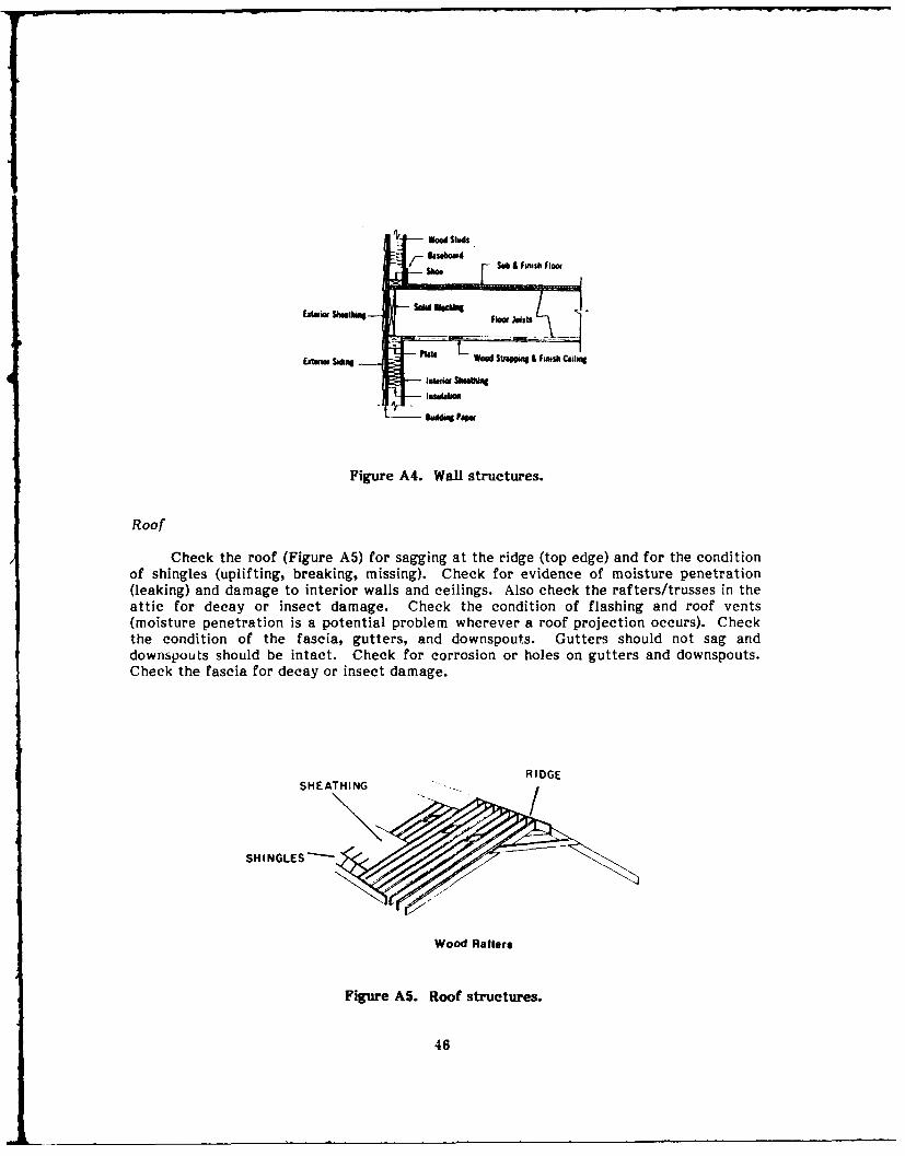
Roof
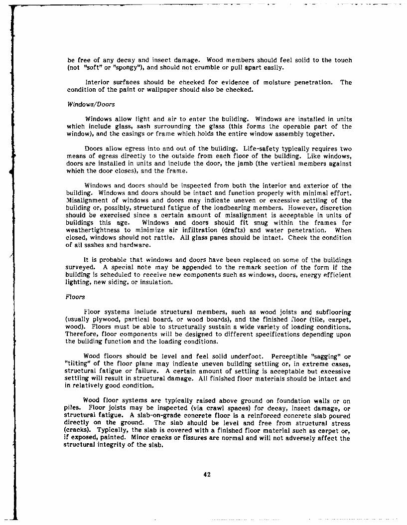
The roof is a weathertight enclosure which is primarily designed to shed water ..ndprotect the interior of the building and its inhabitants from the elements. The roof istypically constructed of parallel rows of wood rafters or a series of trusses which formthe slopes or sides of the roof. The topmost point at which the rafters meet is called theridge. The rafters are covered with wood sheathing (boards or plywood) forming astructural base for applying shingles or other waterproof material. The eaves are theprojection of the roof beyond the wall and the underside is called a soffit. The fascia is aboard enclosing the ends of the rafters.
Check the condition of the roof. The ridge should be straight (level) and the slopesor sides of the roof should appear to be level and uniform. If the roof has a perceptiblesag, it may indicate structural problems in the roof itself or in the walls due to excessiveor uneven building settling. (Evidence of excessive settling may also show up in thealignment of the walls, windows, and doors and as fractures in the foundation walls,piers, or concrete slab).
Check the condition of the shingles. The shingles should lie flat and be a uniformcolor (discoloration indicates wear). Shingles should not be broken or missing.
Water penetration (leaking) is of particular concern around roof projections such asvents and chimneys and at roof junctures (valleys). Typically, all joints are covered witha waterproof material (flashing) such as galvanized metal, bituminous material, or awaterproof membrane. Check to ensure that the flashing is intact and that no waterpenetration has occurred around these joints. Water penetration will be most detectableinside the building (most likely at the wall-to-ceiling junctures). Look for watermarks orstaining on the walls or ceilings. (Water stains may not automatically indicate a leakyroof, but may be attributable to a broken or leaky water pipe or even due tocondensation.)
All gutters and downspouts should be intact and free from corrosion and holes. Thepurpose of the gutters and downspouts is to carry water from the surface of the roof tothe ground beyond the perimeter of the building. Gutters are installed at a slight slope,but will appear level and should not sag. Fascias and soffits should be intact and freefrom decay and insect damage.
Walls
Like the roof, the exterior walls protect the interior of the building and itsinhabitants from the elements. Exterior walls are usually structural or loadbearing andtransfer the weight of the building and its occupants to the ground via the foundation. Inwood framed construction, the walls are constructed of vertical members (studs) coveredwith sheathing and siding on the exterior and gypsum drywall on the interior. Drywall isa composite of layered paper, felt, or fiberboard bonded to a hardened gypsum plastercore. Each drywall panel or sheet is nailed directly to the interior face of the stud walland the joints are taped and finished with a gypsum compound. Drywall may be paintedor covered with wallpaper. The space within the walls serves as a cavity for insulation,electrical wiring and plumbing. Interior nonstructural and nonloadbearing walls arecalled partitions.
The walls should appear vertical and should not buckle, bow, or show structuralstress. Exterior siding should be intact and in good condition. If the siding is paintedwood, the paint should not be cracked, blistered, or peeling. All wood components should
41
be free of any decay and insect damage. Wood members should feel solid to the touch(not "soft" or "spongy"), and should not crumble or pull apart easily.
Interior surfaces should be checked for evidence of moisture penetration. Thecondition of the paint or wallpaper should also be checked.
Windows/Doors
Windows allow light and air to enter the building. Windows are installed in unitswhich include glass, sash surrounding the glass (this forms the operable part of thewindow), and the casings or frame which holds the entire window assembly together.
Doors allow egress into and out of the building. Life-safety typically requires twomeans of egress directly to the outside from each floor of the building. Like windows,doors are installed in units and include the door, the jamb (the vertical members againstwhich the door closes), and the frame.
Windows and doors should be inspected from both the interior and exterior of thebuilding. Windows and doors should be intact and function properly with minimal effort.Misalignment of windows and doors may indicate uneven or excessive settling of thebuilding or, possibly, structural fatigue of the loadbearing members. However, discretionshould be exercised since a certain amount of misalignment is acceptable in units ofbuildings this age. Windows and doors should fit snug within the frames forweathertightness to minimize air infiltration (drafts) and water penetration. Whenclosed, windows should not rattle. All glass panes should be intact. Check the conditionof all sashes and hardware.
It is probable that windows and doors have been replaced on some of the buildingssurveyed. A special note may be appended to the remark section of the form if thebuilding is scheduled to receive new components such as windows, doors, energy efficientlighting, new siding, or insulation.
Floors
Floor systems include structural members, such as wood joists and subflooring(usually plywood, partical board, or wood boards), and the finished floor (tile, carpet,wood). Floors must be able to structurally sustain a wide variety of loading conditions.Therefore, floor components will be designed to different specifications depending uponthe building function and the loading conditions.
Wood floors should be level and feel solid underfoot. Perceptible "sagging" or"tilting" of the floor plane may indicate uneven building settling or, in extreme cases,structural fatigue or failure. A certain amount of settling is acceptable but excessivesettling will result in structural damage. All finished floor materials should be intact andin relatively good condition.
Wood floor systems are typically raised above ground on foundation walls or onpiles. Floor joists may be inspected (via crawl spaces) for decay, insect damage, orstructural fatigue. A slab-on-grade concrete floor is a reinforced concrete slab poureddirectly on the ground. The slab should be level and free from structural stress(cracks). Typically, the slab is covered with a finished floor material such as carpet or,if exposed, painted. Minor cracks or fissures are normal and will not adversely affect thestructural integrity of the slab.
42

Mechanical/Electrical
Mechanical and electrical systems are the support function of the building,promoting the safety and comfort of its inhabitants. The mechanical system includes theheating, ventilation, and air conditioning (HVAC) system as well as the plumbing system.
The heating and cooling requirements for each building will vary depending uponthe climate and building use. Insulation may or may not have been added to the floors,walls, and roof to increase heating and cooling efficiency. Heating systems are generallydivided into three main categories: forced air (requiring ducts), hot water (using pipes),and electric (using radiant coils). Most of the mechanical equipment is enclosed withinthe building structure and may not be accessible. Generally, it is only imperative todetermine whether the system is functional.
Waterlines are typically small diameter pipes (1/2 to 2 in.) of copper, galvanizedsteel, or plastic (PVC) material. All valves and fixtures should should be intact andoperable. Check for water leaks around valves and joints.
Sewerlines are large diameter pipes (4 to 6 in.) designed to carry waste water andsewerage from the building. Most of the sewerline will be below the ground andinaccessible. However, water should drain efficiently from all fixtures.
It is important to check the condition of the incoming electrical lines to thebuilding. The electrical feeder may either be brought into the building overhead or belowground. If exposed, check the condition of the wiring for noticeable wear or fraying.Check the electrical service panel. The circuits will most likely have fuses or, ifupdated, breaker switches. In general, the electric system should be operable, lightfixtures, switches, and outlets intact, and the electrical wiring should conform withNational Electrical Council (NEC) specifications.
Life-Cycle
The life-cycle information is intended to be a summary of repairs, alterations ormodifications, or replacements of the building's components throughout its history. Thisinformation will be completed by the investigator in conjunction with qualified militarypersonnel.
For each question, mark the most appropriate response. If the component has beenrepaired, altered, or replaced, give the most recent date. Estimate the percentage ofthe building area used for the specific building function. For instance, if the building isadministrative and the total building area is dedicated to this function, then thebuilding's efficiency would be rated at 100 percent.
Assessment Form Summary
BUILDING DATA
1. Record building number (FORSCOM classification number)2. Record year built3. Record building size (area in Square Feet [SF] or perimeter in Linear Feet
[LF] length x width)
43

4. Record building typology (check appropriate boxes)
5. Record building use (Intended Use, Design Use, and Actual Use)
BUILDING FLOOR PLAN DIAGRAM
1. Draw schematic floor plan of building to scale (building perimeter)a. Existing plan (solid lines)b. Original construction or modifications (dashed lines)
REMARKS
1. Note general comments or observations pertaining to overall condition ofbuilding components or building structure or building finishes
2. Note general comments or observations pertaining to changes in use and/ormodifications to original building plan
BUILDING COMPONENTS
1. Record relative conditions of each building component (Figure A2)a. Not Applicableb. Floor Condition (requires major repair or replacement)c. Average Condition (requires minor repair or maintenance)d. Good Condition (requires no repair)e. Not Accessible
2. Cross reference listed components with Building Component Index (below) forlocation and description of component systems
Building Component Index
Foundation
Indicate the type of foundation and assess its condition (Figure A3). Check forcracks or excessive settling in the foundation wall. Check the building/foundation con-nection at the top of the foundation wall for decay, insect damage, etc. Check for un-usual movement (cracking or buckling) of the concrete floor slab-on-grade. Check thewood piles for decay or insect damage. Check concrete piles for cracking or unusualsettling.
Note: Evidence of excessive settling may be detected in sagging roof, canted (non-vertical) walls, tilted floors, and misalignment of doors and windows. Severe settlingmay cause structural damage to the foundation, joists, studs, and rafters.
Walls
Check the condition of the walls (Figure A4). Walls should appear "plumb" orvertical. Indicate the exterior siding type (wood, asbestos, other) and condition. Checkfor decay or insect damage and that the siding is intact (no loose or missing pieces).Check the paint condition (blistering, peeling, checking, etc.) Check the condition ofinterior walls and partitions for cracks or damage and for the condition of the paint/wallcovering.
Note: Check all load-bearing walls and columns for signs of structural stress(cracking, buckling, or failure).
44

-q
Waterproofing
Spread footings
Strip footing
STRIP FOOTING
fi,b. I. ian4on jowlw . u.h .1into ,g
7 Cu. . Slab'
~l 11 4 vaofem o
~ii ~idiCompacted Gicel
SLAB ON GRADE
II
I>11 1
Figure A3. Foundations.
45
Wood Sluds
Sh Su &&ae f uifimsh floof
-- Aplate ,,d S UIP* i FIih 411 1
ESdiw SiPnw
Figure A4. Wall structures.
Roof
Check the roof (Figure A5) for sagging at the ridge (top edge) and for the conditionof shingles (uplifting, breaking, missing). Check for evidence of moisture penetration(leaking) and damage to interior walls and ceilings. Also check the rafters/trusses in theattic for decay or insect damage. Check the condition of flashing and roof vents(moisture penetration is a potential problem wherever a roof projection occurs). Checkthe condition of the fascia, gutters, and downspouts. Gutters should not sag anddownspouts should be intact. Check for corrosion or holes on gutters and downspouts.Check the fascia for decay or insect damage.
RIDGE
SHEATHING RIDGE
SHINGLES---
Wood Raftere
Figure A5. Roof structures.
46

Floors
Check the condition of the floor (Figure A6). It should be level (should not sag).Check that th, finor is solid undcrf,ot. It zhould not bounee ur seem "spongy." In tnetrawl space, check the floor joists for decay or insect damage and cracks. Joist shouldappear solid, not "punky." Check the floor/wall connection for decay or insect damageand check the finish of the floor coverings (carpet, tile, etc.).
Windows/Doors
Check the condition of window frames, sashes, and glass (Figure A7). Check forbroken or missing panes, moisture penetration, decay, or insect damage. Check that thewindows are intact and function properly. (Windows should fit snug in the frame).
Check the condition of door frames, thresholds, and hardware (Figure A7). Checkthat the door is intact and functions properly. Check for decay, insect damage, moisturepenetration, and paint condition.
FLOORING
FLOORCARPET
Wood Joist Wood Beam and Joist
Figure A6. Floor structures.
FRAME
- iPANES
SASH-
THRESHOLD
Exterior Door System
Figure A7. Window/door structures.
47

Mechanical Systems
Check for breaks or cracks in hot and cold water lines (Figure A8). Check thejoints and connections for leaks. Check to see if the valve,; operate properly. Check thesewerline. Water should drain easily. Check the condition of waterheaters. They shouldbe operational and show no corrosion on the outer jacket. Check the condition offixtures (sinks, toilets). Check the condition of the ductwork, heating unit, and/or airhandling unit. All systems should be operational.
Electrical Systemi
Check the condition of the electrical wiring, lighting, and service panel (FigureA9). Check that the outlets and switches are operational. Also check the electric linesfeeding to the service panel for signs of wear or breakage.
Gas Fied
Forced Hol Wite Heeling System
Figure A8. Mechanical systems.
Feeder InItchgee'
IcIdiC $eice wicl
Figure A9. The electrical system.
48
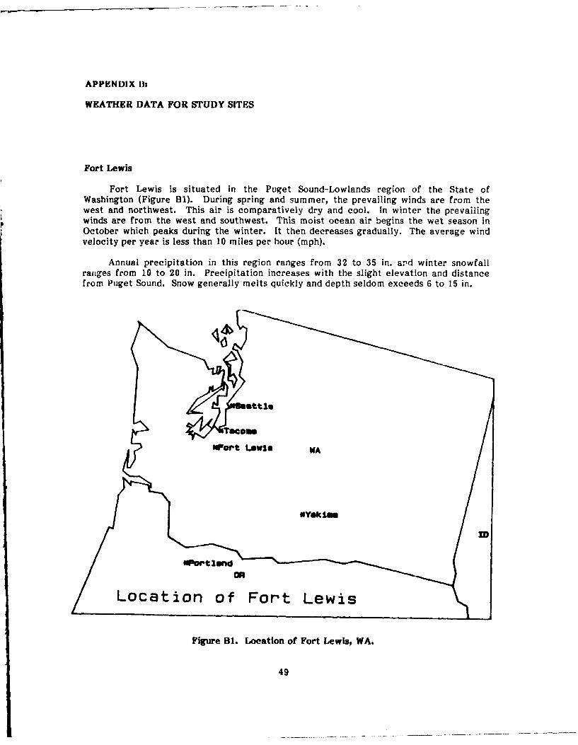
APPENDIX Ils
WEATHER DATA FOR STUDY SITES
Fort Lewis
Fort Lewis is situated in the Puget Sound-Lowlands region of the State ofWashington (Figure BI). During spring and summer, the prevailing winds are from thewest and northwest. This air is comparatively dry and cool. In winter the prevailingwinds are from the west and southwest. This moist ocean air begins the wet season inOctober which peaks during the winter. It then decreases gradually. The average windvelocity per year is less than 10 miles per hour (mph).
Annual precipitation in this region ranges from 32 to 35 in. and winter snowfallranges from 10 to 20 in. Precipitation increases with the slight elevation and distancefrom Puget Sound. Snow generally melts quickly and depth seldom exceeds 6 to 15 in.
0ag't Leawim WAatliTeyc l
Wart Leis K
Locaion of Fort Lewis
Figure BI. Location of Fort Lewis, WA.
49

The January maximum temperature ranges from 41 to 45 'F, and the minimumtemperature ranges from 28 to 32 °F. Minimum temp9eratures from 0 to -10 OF havebeen recorded but temperatures seldom drop below 10 F. During July, the temperature.anges from 73 OF near the Canadian border to 78 OF in the vicinity of Olympia. Theminimum summer temperature is approximately 50 OF. Temperatures can reach 100 OFbut during an average summer there are only three to five days with temperaturesexceeding 90 'F.
In the Puget Sound region, and particularly in the Seattle-Tacoma vicinity, theaverage annual relative humidity is 85 percent in the early morning and 64 percent in theearly evening.
Fort Hood
Fort Hood is located in the central region of Texas (Figure B2). The prevailingwind direction is from the south throughout the entire year. The average annual windvelocity is 11.7 mph, reaching a peak of 13.8 mph during March and April. Tornadoeshave occurred in Texas during all seasons, but they are most frequent during April, May,and June.
CK 10 , TN
*Austin
Figure B2. Location of Fort Hood, TX.
50

Average rainfall in the central region is between 32 and 36 in. Rains occur most
frequently in late spring, peaking in May. July and August are relatively dry months.".-'fall rarelv interferes with outdoor operations for more than an hour or two at a
time. Snows of 4 in. or more are unusual.
The maximum temperature in winter for the central Texas region is 58 OF and the
minimum temperature for January is 36 OF. The summer maximum temperature is
96 OF. The minimum temperature in July is 72 OF. The average annual temperature for
central Texas is 66 to 68 OF.
The annual relative humidity in the central region is 82 percent in the early
morning and 54 percent in the early evening.
Fort Ord
Fort Ord is situated on the Pacific coast of California, approximately 110 miles
south of San Francisco, a few miles nortneast of Monterey, along the western side of the
Coast Range (Figure B3). The climate is dominated by the influence of the Pacific
Ocean. Warm winters, cool summers, small daily and seasonal temperature ranges, and
high relative humidities are characteristic for this area.
%*sit LakeScity
rPumntisco
uort Ord
CA
Angles
Location f Fort Ord
Figure B3. Location of Fort Ord, r
51
L ..... . . ..
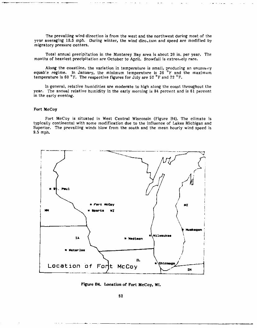
The prevailing wind direction is from the west and the northwest during most of theyear averaging 10.5 mph. During winter, the wind dire..tion and speed are modified bymigratory pressure centers.
Total annual precipitation in the Monterey Bay area is about 20 in. per year. Themonths of heaviest precipitation are October to April. Snowfall is extrermely rare.
Along the coastline, the variation in temperature is small, producing an unusuaiiyequab'e regime. In January, the minimum temperature is 36 OF and the maximumtemperature is 60 OF. The respective figures for July are 52 OF and 72 OF.
In general, relative humidities are moderate to high along the coast throughout theyear. The annual relative humidity in the early morning is 84 percent and is 61 percentin the early evening.
Fort McCoy
Fort McCoy is situated in West Central Wisconsin (Figure B4). The climate istypically continental with some modification due to the influence of Lakes Michigan andSuperior. The prevailing winds blow from the south and the mean hourly wind speed is9.5 mph.
0 .Paul 2
of For-t McCoy MZ
MH sports WX
Figure B4. Location of Fort MCoy, WI.
52
The annual precipitation ranges from 30 to 34 in. over most of the region. Theaverage seasonal snowfall varies significantly across the state, from about 30 in. near thesouthern border to over 100 in. in the north.
The maximum temperature is 103 OF in July. The minimum temperature is -37 OFin January.
The relative humidity is 81 percent in the early morning and 63 percent in the earlyever,ing.
About four tornadoes occur each year. Tornado frequency is highest in June andJuly, followed in order by April, May, and September.
53

APPENDIX C:
TABULATED BUILDING INSPECTION DATA
Table Cl
Year Built
Fort Fort FortLewis Hood Ord
1940 - - 41941 9 - 41942 - 5 -
1943 1 - 11944 - -1945 2 - -
unknown 1 - 1
Total 13 5 10
Table C2
Building Size
Fort Fort FortSq ft Lewis Sq ft Hood Sq ft Ord
1144 2 3100 1 2206 12207 1 3241 1 2740 12323 1 5310 2 2892 14720 4 9000 1 4688 16136 1 - - 4720 16220 1 - - 8608 16809 1 - - unknown 17420 1 - - -unknown 1 - - -
Total 13 5 10
54

Table C3
Usage
Fort Fort FortLewis Hood Ord
D* I A D I A D I A
generalstorage - 1 - 2 2 1 2 2 2administration 1 1 1 1 3 4 1 2 4enlisted barracks 7 6 1 2 - - 4 3 1general instruction - 1 6 - - - - -
detached day center 1 1 1 - - - - -
mess hall 3 2 3 - - - 2 2 2unknown 1 1 1 - - - 1 1 1
Total 13 13 13 5 5 5 10 10 10
*D=Design, I=Intended (Recommended), A-Actual (Current) Usage.
Table C4
Type of Construction
Fort Fort FortLewis Hood Ord
one-story 6 3 6two-story 7 2 4
Total 13 5 10
55

Table C5
Foundation
Fort Fort FortLewis Hood Ord
spread footings/piles 10 5 7slab-on-grade 2 - 2both I - 1
Total 13 5 10
Table C6
Exterior Finish
Fort Fort FortLewis Hood Ord
wood - 2 9asbestos 11 - -metal/vinyl 2 3 1
Total 13 5 10
Table C7
Handicapped Access
Fort Fort FortLewis Hood Ord
not answered 1 2 4yes - 1 1no 12 2 5
Total 13 5 10
56

Table C8
Insulation
Fort Fort FortLewis Hood Ord
not answered 6 3 8floor - - -walls - - -
roof -
walls and roof 1 1 2none 6 1 -
Total 13 5 10
Table C9
Capacity
Fort Fort FortLewis Hood Ord
0 1 2 219 - 1 -
23 - - I24 1 - -
25 227 - - 128 1 - -30 2 - -36 2 - 350 - 2 -140 3 - -
200 - - 1250 - - 1unknown 1 - 1
Total 13 5 10
57

Table C 10
Structure
Not Not NotComponent/Fort app* Poor Aver Good ace arts Total
FoundationLewis - - 11 1 1 - 13Hood - - 2 1 - 2 5Ord - - 6 2 - 2 10
Walls (exterior)Lewis - 2 9 2 - - 13Hood - - 2 3 - - 5Ord - - 7 1 - 2 10
RoofLewis - 4 8 1 - - 13Hood - - 2 3 - - 5Ord - 5 3 1 - 1 10
First FloorLewis - - 9 3 - 1 13Hood - 2 - 3 - - 5Ord - 1 8 - - 1 10
Second FloorLewis 5 - 4 2 - 2 13Hood 3 - 2 - - - 5Ord 5 - 3 - 2 10
Stairs (interior)Lewis 5 - 6 - 2 13Hood 3 2 - - 5Ord 4 1 3 - - 2 10
*Not app=not applicable, Aver=average, Not acc=not accessible, Not ans=not answered.
58

Table C 11
Exterior Siding
Not Not NotComponent/Fort app* Poor Aver Good acc ans Total
WoodLewis 1 - - 1 - 11 13Hood - - 2 - - 3 5Ord 1 1 5 - - 3 10
AsbestosLewis - 2 8 1 - 2 13Hood 2 - - - - 3 5Ord 6 .- - 4 10
PaintingLewis - 1 9 2 - 1 13Hood 2 2 - - - 1 5Ord - 2 1 4 - 3 10
Steps/StoopsLewis - 2 9 1 - 1 13Hood - 2 - 2 - 1 5Ord 1 - 6 - - 3 10
RampsLewis 3 2 6 - 2 13Hood 3 - - 1 - 1 5Ord 7 .- - 3 10
*Not app=not applicable, Aver=average, Not acc=not accessible, Not ans=not answered.
59

Table C12
Exterior Walls/Doors
Not Not NotComponent/Fort app* Poor Aver Good ace ars Total
WindowsLewis - 8 2 3 - - 13Hood - 2 - 2 - 1 5Ord - 4 6 - - - 10
GlassLewis - 4 5 4 - - 13Hood - 1 1 2 - 1 5Ord - - 9 1 - - 10
SashLewis - 4 6 3 13Hood - 2 -?1 5Ord - 4 6 - 10
FrameLewis - 6 4 3 - 13Hood - 2 - 2 1 5Ord - 2 7 - - 1 10
Storm ScreenLewis 9 - 3 1 - - 13Hood - - - - 5 5Ord 8 - - - 2 10
Exterior DoorsLewis - 3 9 - 1 13Hood - - - 5 5Ord - 1 5 2 - 2 10
Door FrameLewis 3 8 1 - 1 13Hood - 2 2 - - 1 5Ord - 1 4 2 - 3 10
HardwareLewis 2 - 4 7 - - 13Hood - 2 - 2 - 1 5Ord - 1 4 2 - 3 10
*Not app=not applicable, Aver=averave, Not acc=not accessible, Not ans=not answered.
60
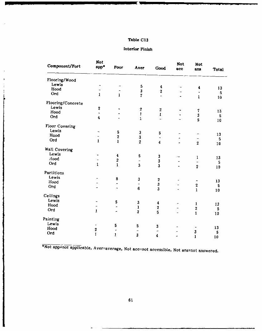
Table C13
Interior Finish
Not Not NotComponent/Fort app* Poor Aver Good ace ans Total
Flooring/WoodLewis 5 4 - 4 13Hood 3 2 5Ord 1 1 7 - 1 10
Flooring/ConcreteLewis 2 2 2 - 7 13Hood 1 1 - 3 5Ord 4 - 1 - - 5 10
Floor CoveringLewis - 5 3 5 - - 13Hood 2 3 - - 15Ord 1 1 2 4 - 2 10
Wall CoveringLewis - 4 5 3 1 13Hood - 2 - 3 - - 5Ord 1 1 3 3 - 2 10
PartitionsLewis - 8 3 2 - - 13Hood - - 3 - 2 5Ord - 6 3 - 1 10
CeilingsLewis - 5 3 4 - 1 13Hood - 1 2 - 2 5Ord 1 - 3 5 1 10
PaintingLewis - 5 5 3 - - 13Hood 2 - - 3 5Ord 1 1 3 4 - 1 10
*Not app=not applicable, Aver=average, Not acc=not accessible, Not ans=not answered.
61

Table C14
Plumbing
Not Not NotComponent/Fort app* Poor Aver Good ace ans Total
Water LinesLewis 2 2 3 - 6 13Hood - - - 1 3 1 5Ord 1 6 - - 3 10
Hot WaterLewis 1 1 6 3 - 2 13Hood - - - 2 1 2 5Ord - 2 5 - 1 2 10
Cold WaterLewis 1 1 6 3 - 2 13Hood - - - 2 1 2 5Ord - 2 5 - 1 2 10
Sewer LinesLewis 2 1 4 2 1 3 13Hood 2 - - 1 2 - 5Ord - 3 1 - 5 1 10
Water HeatersLewis 2 1 3 - 2 5 13Hood - - - - 1 4 5Ord 1 1 2 2 1 3 10
FixturesLewis 3 1 2 3 - 4 13Hood 2 - - 2 - 1 5Ord 2 - 4 2 - 2 10
ToiletsLewis 4 1 5 1 - 2 13Hood 2 - - 2 1 5Ord 2 - 5 3 - - 10
LavoratoriesLewis 4 1 5 1 - 2 13Hood 2 - - 2 - 1 5Ord 2 1 4 - - 3 10
Shower/BathsLewis 4 1 4 2 - 2 13Nuod 4 - - - - 1 5Ord 7 - 1 1 - 1 10
*Not app=not applicable, Aver=average, Not acc=not accessible, Not ans=not answered.
62
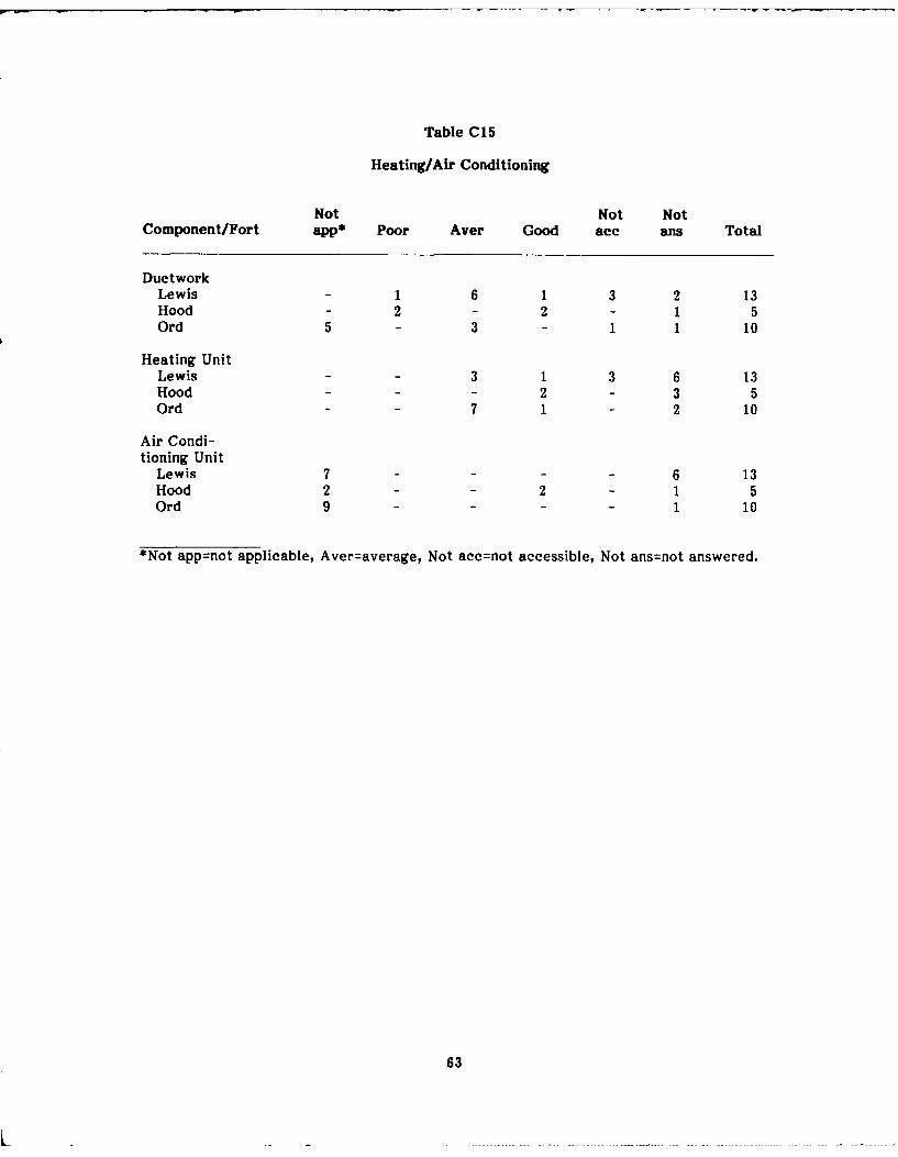
Table C15
Heating/Air Conditioning
Not Not NotComponent/Fort app* Poor Aver Good ace ans Total
DuctworkLewis 1 6 1 3 2 13Hood - 2 - 2 - 1 5Ord 5 - 3 - 1 1 10
Heating UnitLewis - - 3 1 3 6 13Hood - - 2 - 3 5Ord - - 7 1 - 2 10
Air Condi-tioning Unit
Lewis 7 - - - - 6 13Hood 2 - - 2 - 1 5Ord 9 - - - 1 10
*Not app=not applicable, Aver=average, Not acc=not accessible, Not ans=not answered.
63
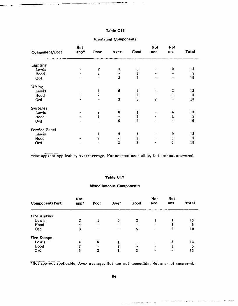
Table C16
Electrical Components
Not Not NotComponent/Fort app' Poor Aver Good ace ans Total
LightingLewis - 2 3 6 - 2 13Hood - 2 - 3 - - 5Ord - - 3 7 - - 10
WiringLewis - 1 6 4 - 2 13Hood - 2 - 2 - 1 5Ord - - 3 5 2 - 10
SwitchesLewis - 2 6 1 - 4 13Hood - 2 - 2 - 1 5Ord - - 5 5 - - 10
Service PanelLewis - 1 2 1 - 9 13Hood - 2 - 2 - 1 5Ord - - 3 5 - 2 10
*Not app=not applicable, Aver=average, Not acc=not accessible, Not ans=not answered.
Table CIT
Miscellaneous Components
Not Not NotComponent/Fort app* Poor Aver Good ace ans Total
Fire AlarmsLewis 2 1 5 2 1 1 13Hood 4 - - - - 1 5Ord 3 - - 5 - 2 10
Fire EscapeLewis 4 5 1 - - 3 13Hood 2 - 2 - - 1 5Ord 5 2 1 2 - - 10
*Not app=not applicable, Aver=average, Not acc=not accessible, Not ans=not answered.
64

GLOSSARY
STRUCTURE
Footing: An enlargement at the lower end of a foundation wall, pier, or column designedto distribute the load.
Foundation: The substructure or base supporting a building.
Pier: A vertical structural support.
Pile: A long slender column of timber, steel, or reinforced concrete driven into theground to carry a load.
Sill Plate: A horizontal piece that forms the lowest member or one of the lowestmembers of a framework or supporting structure.
WALL
Drywall: A board used in large sheets in walls and consisting of several plies offiberboard, paper, or felt bonded to a hardened gypsum plaster core.
Partition: An interior dividing wall (usually nonstructural or nonloadbearing).
Sheathing: The first covering of boards or of waterproof material on the outside wall ofa frame building.
Stud: One of the uprights in the framing of the walls of a building to which sheathing,paneling, or laths are fastened.
ROOF
Collar Tie: The horizontal member of a roof connecting opposite rafters (locatedbetween the ridge beam and the ceiling joists).
Eaves: The lower border of the roof that overhangs the wall.
Fascia: A board enclosing the ends of the rafters.
Flashing: Sheet metal, bituminus material, or other waterproof material to protectagainst rain.
Rafter: Any of the parallel beams that support a roof.
Ridge: The line of intersection at the top between the opposite slopes or sides of a roof.
Soffit: The underside of a part or member of a building (as of an overhang or staircase).
Truss: A rigid framework forming the structural members of a roof.
65
FLOOR
Bridging: Small crossed wood or metal members between floor joists.
Joist: Any of the small timbers or metal beams ranged parallel from wall to wall in astructure to support the floor.
Slab: A flat rectilinear architectural element that is usually formed of a single piece ormass (concrete floor).
Subfloor: A layer of boards or plywood laid horizontally over 'loor joists to support thefinished floor.
WINDOW/DOOR
Frame: The open case or structure made for enclosing or supporting a window or door.
Jamb: An upright piece or surface forming the side of an opening (window, door).
Sash: The framework in which panes of glass are set in -- window or door (usually formsthe moveable part of a window).
Threshold: The plank, stone, or piece of timber that lies under a door.
66
USA-CERL DISTRIBUTION
Chief of Engineers Charleston 29402 5th US Army 78234ArrN: DAEN-ZCI ATTN: Chief, Engr Div ATTN. AKFY-LG-EATTN. CEEC-M (2) Savannah 31402ATN: CEEC-ZA ATTN. Chief, SASAS-L 7th US Army 0940?Jaksonville 32232 TN ~r-~-GE
ATTN. Env. Res. r.ATN AETTM-D1Ir-MG-EEFORSCOM (28) Mobile 34828 172nd Infantry Brigde 98733ATTrN. CESAM-PI-ERIME A72n. AnFZTryFG-~E 973FORSCOM Engineer, ATTN: Spt Det. Nashville 3720 ATTN: AFZT-FG-EHATTN. Facilities Engineer ATTN* Chief, ORNEO-P US Army Western Command 96858
Fort Buchanan 00934 Memphis 33103USAmWetrCo an965Fort Bragg 28307 ATTN: APRM-MCFort Campbell 42223 ATrTN: Chief, LMMED-PRFort Campel 4223 Vicksburg 39180 USA ARRADCOM 07801Fort Carscn 80013 ATTN: Chief, Engr Div ATTN: DRDAR-LCA-OKFort Devens 01433 Louisvlle 40201Fort Drum 13601 ArTN. Chief, Engr Div West Point, NY 10996Fort A.P. Hill 22427 St. Paul 55101 ATTN: Dept of MechanicsFort AH l 7654 7 ATTN. NCSPD-ER ATTN. LibraryFort Hood 76544 Chizeago $9604A'r:Lbry
Fort Indiantown Gap 17003 ATTN Chief. NCCPD-ERFort Irwin 92310 A N Chief, NCCP-EVA 2200Fort San Houston 78234 AN C f NCCPE-PES ATTN. Learning Resources CenterFortSan ouson 7234St. Louis 63101Fort Lewis 98433 ATT N: Chief, ED-B Ft. Lee, VA 23801Fort MaCarthur 90731 Kansas City 84106 Ft. A 230Fort McCoy 54656 ATTN: Chief, Engr Div ATTN. AMXMC-D (2)Fort McPherson (2) 30330 Omaha 88102Fort George G. Meade 20755 ATTN: Chief, Engr Div Ft. McPherson, GA 30330Fort Ord 93941 Little Rock 72203 ATTN: AFEN-CDFort Picket 23824 ATTN Chief, Engr Div Ft. Monroe, VA 2385Fort Polk 71459 Tulsa 74131 Ft.roe ATE 365LFort Richardson 99505 ATTN: SWTED ATTN. ATEN-ADFort Riley 68442 Fort Worth 76102 ATTN: ATEN-FE-USPredisio of San Francisco 94129 ATTN: Chie. SWFPL-RFort Sheridan 60037 ATTN: Chief, SWFED-F ATTN. NGB-ARI-EFort Stewart 31314 Galveston 77553Fort Wainwright 99703 ATTN: Chief, SWGAS-L US Naval Oceanographic Office 39522Vancouver Bks. 98680 ATrN. Chief, SWGCO-M ATTN. Libreyra
Albuquerque t710tTRADOC (19) ATTN Chief, Engr Div KirtiandAFB, NM 87117HQ, TRADOC, ATTN ATEN-DEH 23851 Los Angeles 90053 and AFB.NT7A TN: DEH AT'TN: Chief, SPLED-E ATTN. AFWLINTE
Fort Belvoir 22060 San Francisco 94105 Little Rock AFO 72099Fort Benning 31905 ATTN: Chief, Engr Div AittN 314/DE 2Fort Bliss 79916 Sacramento 95814Carlisle Barracks 17013 ATTN: Chief, SPKED-D Tinker AF, OK 73145Fort Chaffee 72905 Far East 96301Fort Dix 00640 ATTN: POFED-L 2854 ABC/DEFort Eustie 23604 Seattle 98124Fort Gordon 30905 ATTN. Chief. NPSEN-PL-WC Building Research Board 20418For! Hamilton 11252 ATTN: Chief, NPSEN-PL-ER Dept. of TransportationFat Benjamin Harrison 48216 ATTN: Chief, NPSEN-PL-BP Tallahassee, FL 32301Fort Jackson 29207 Walls Wails 99362Fort Knox 40121 ATTN. Chief, Engr Div Dept. of Transportation Library 20590Fort Leavenworth 68027 Alaska 99508Fort Lee 23801 ATTN: NPAEN-G-M Transportation Research Board 20418Fort McClellan 38205Fort Rucker 36362 US Army Engineer DivisionFort Sill 73503 New England 02154Fort Leonard Wood 65473 TTN: Laboratory 125
ATTN: Chief, NEDED-E S8/8Defense Technical Info. Center 22314 South Atlantic 30303
ATTNz DDA (2) ATTN: Chief, SADEN-E
Huntsville 35507US Army Engineer District ATTN Chief, HNDED-CS
New York 10278 ATTN CMef, HNiED-MATTN: Chief. Desirn Hr. Lower Mississippi Valley 39180
Pittsburgh 15222 ATTN Chief, PD-RATTN: Chief, Engr Div Ohic ver 45201
Phildephia 19106 AM'N: Chief, Engr DivATTN: Chief. NAPEN-E North Central 60405
Baltimore 21203 ATTN: Chief, Engr. Planning Br.ATTN: Chief. Engr Div Southwestern 75242
Norfolk 23510 ATTN Chief, SWDCO-OATTN: Chief, NAOEN-R South Pacific 94966
Huntington 25721 ATTN: LaboratoryATTN: Chief, ORHED-P Pacific Ocean 96856
Wilmington ATTN: Chief, Engr DivATTN: Chief, SAWEN-PP 28401 ATTN: Chief, PODED-PATTN: Chief, SAWEN-PM 28401 North PacificAT TN: Chief, SAWPD-E 28402 ATTN: Laboratory 97060
ATTN: Chief, Engr Div 97208