An Assistive Surgical MRI Compatible Robot First Prototype...
26
19 An Assistive Surgical MRI Compatible Robot – First Prototype with Field Tests Tapio Heikkilä 1 , Sanna Yrjänä 2 , Pekka Kilpeläinen 1 , John Koivukangas 2 and Mikko Sallinen 1 1 VTT Technical Research Centre of Finland 2 Department of Neurosurgery, University of Oulu, Oulu, Finland 1. Introduction 1.1 Overview Magnetic Resonance Imaging (MRI) is superior to other imaging modalities in detecting diseases and pathologic tissue in the human body. The excellent soft tissue contrast allows better delineation of the pathologic and surrounding structures. For example, brain surgery requires exact three-dimensional orientation to piece together anatomical and pathological locations inside the brain. The target location can be seen in the preoperative MRI and neuroradiologists can give assessments, e.g., of tumor nature. Still, factors affecting the resection technique e.g. density of neovasculature and consistency of tumor tissue cannot always be evaluated beforehand. Intraoperative MRI (IMRI) - complementing preoperative MRI – is continuously being developed to give additional information to the neurosurgeon (Tuominen et al., 2002, Yrjänä, 2005). Robot technology can contribute to working conditions and efficiency of IMRI operations and robots that are compatible with MRI devices represent a new and promising special field in robotics, which can improve clinical diagnostics and treatment for internal diseases, including neurologic ones (Gassert et al., 2008). There are several commercial solutions in operation for surgical robots such as Da Vinci, Minerva, NeuroMate and PathFinder just to mention few but not yet for operation in MRI devices (Zhijiang & Lining, 2003), (Dasgupta & Henderson, 2010), (Jaara, 2007). One solution for assistive surgery is the minimally surgically invasive (MIS) robot which is a large, multi-arm system (Zoppi et. al., 2010). Such kinds of systems are expensive which makes them difficult to reach common use. 1.2 State-of-the-art Development of MRI compatible robots implies multidisciplinary work. Solutions from conventional robotics are not applicable as such even if the development of such a system is similar to design of a mechatronic device (Cleary & Nguyen, 2001). Strong static and coupling magnetic fields and radio frequency pulses produced by the MRI devices make for a challenging and potentially hazardous environment. Magnetic fields exert forces and eddy www.intechopen.com
Transcript of An Assistive Surgical MRI Compatible Robot First Prototype...
19
An Assistive Surgical MRI Compatible Robot – First Prototype with Field Tests
Tapio Heikkilä1, Sanna Yrjänä2, Pekka Kilpeläinen1, John Koivukangas2 and Mikko Sallinen1
1VTT Technical Research Centre of Finland 2Department of Neurosurgery, University of Oulu, Oulu,
Finland
1. Introduction
1.1 Overview
Magnetic Resonance Imaging (MRI) is superior to other imaging modalities in detecting diseases and pathologic tissue in the human body. The excellent soft tissue contrast allows better delineation of the pathologic and surrounding structures. For example, brain surgery requires exact three-dimensional orientation to piece together anatomical and pathological locations inside the brain. The target location can be seen in the preoperative MRI and neuroradiologists can give assessments, e.g., of tumor nature. Still, factors affecting the resection technique e.g. density of neovasculature and consistency of tumor tissue cannot always be evaluated beforehand. Intraoperative MRI (IMRI) - complementing preoperative MRI – is continuously being developed to give additional information to the neurosurgeon (Tuominen et al., 2002, Yrjänä, 2005).
Robot technology can contribute to working conditions and efficiency of IMRI operations and robots that are compatible with MRI devices represent a new and promising special field in robotics, which can improve clinical diagnostics and treatment for internal diseases, including neurologic ones (Gassert et al., 2008). There are several commercial solutions in operation for surgical robots such as Da Vinci, Minerva, NeuroMate and PathFinder just to mention few but not yet for operation in MRI devices (Zhijiang & Lining, 2003), (Dasgupta & Henderson, 2010), (Jaara, 2007). One solution for assistive surgery is the minimally surgically invasive (MIS) robot which is a large, multi-arm system (Zoppi et. al., 2010). Such kinds of systems are expensive which makes them difficult to reach common use.
1.2 State-of-the-art
Development of MRI compatible robots implies multidisciplinary work. Solutions from conventional robotics are not applicable as such even if the development of such a system is similar to design of a mechatronic device (Cleary & Nguyen, 2001). Strong static and coupling magnetic fields and radio frequency pulses produced by the MRI devices make for a challenging and potentially hazardous environment. Magnetic fields exert forces and eddy
www.intechopen.com
Explicative Cases of Controversial Issues in Neurosurgery
434
currents on materials that are magnetically incompatible or conduct electricity. This may lead to wrong signal information, uncertainties in actuator control and dangerous forces in the construction if they are located in too strong a magnetic field (Virtanen, 2006). Limited working space, limited access to this space, need for line of sight to MR images and comfort of patients and surgeons set additional constraints.
Analysis for optimal design for MRI compatible robots has been proposed by (Gasparetto & Zanotto, 2010). Many MRI compatible robotic devices have also been reported, for biopsies according to the target [for brain (Masamune et al., 1995), breast (Larson et al., 2004), prostate (Susil et. al., 2003)] and also to the structure of the MRI device (Chinzei & Miller, 2001), (Tsekos et al., 2005). To solve the challenge of operation in limited space, a manipulator with several degrees of freedom seems to be best solution, as also proposed in this paper. One solution for that has also been introduced by (Chinzei et. al, 2000). It has good reach by using two manipulator arms but compared to our solution, accuracy is more limited due to lack of efficient calibration. Development of a general purpose device has also been reported (Tsekos et al., 2008).
In comparison, if very high accuracy is needed, also parallel kinematic structures have been presented (Plante et. al., 2009). By constructing the manipulator using dielectric elastomer actuators, here 6 parallel, absolute position accuracy of 1,8mm Root Mean Square (rms) can be reached. Use of this kind of robot structure is limited typically to a volume of a 80x70mm2 ellipse which limits its use. Operation accuracy has been improved by developing advanced human-robot co-operation where the robot guides the human during the surgery by virtual fixtures which are controlled by using force control, i.e. 6 Degrees-of-Freedom (DOF) force and torque sensor attached to the wrist of the robot (Castillo-Cruces & Wahrburg 2010).
The manipulators developed make use of different methods of actuation, mainly according to four main categories (Elhawary et. al., 2005): transmission by hydraulic or pneumatic actuators, ultrasonic motors based on the piezoceramic principle and remote manual actuation. Progress in materials, position sensing, different actuation techniques, and design strategies have contributed to the technical feasibility in MRI environments, but still most systems lack clinical validation, which is needed for commercial products (Elhawary et. al., 2005), (Gassert et al., 2008). Most advanced example is the NeuroArm (Pandya et al., 2009) which has been developed for open neurosurgical procedures in IMRI environments. NeuroArm is an image-guided, MRI compatible robotic system that is capable of both microsurgery and stereotaxy. However, it is still a manipulator type device where the robot motion control is based on surgeon’s manual operations of the joystick type control devices supported by on-line visual information of the MRI device.
Our goal has been a device with portable and readily locatable kinematic structure enabling a variety of applications, like assisting biopsies, tumor operations, and installing automatic dosage implants. Especially requirements from brain surgery, originating from the IMRI guided operations at the Oulu University Hospital (Yrjänä, 2005) have been guiding our work. Semiautomatic operation was targeted where the tool, e.g., a biopsy needle is taken automatically very close to the target location (“entry point”), and final adjustment and needle motions are carried out by the surgeon or at least with tight supervision by the surgeon. The requirement for accuracy of automatic motions is at the level of +/- 1-2 mm for the needle. Finally, we sought to achieve optimal performance within a volume corresponding to that of the human head, our “region of surgical interest” (Koivukangas et al., 2003).
www.intechopen.com
An Assistive Surgical MRI Compatible Robot – First Prototype with Field Tests
435
The dimensions of the MRI device and characteristics of the changing magnetic field sets constraints to the robot constructs and dimensions as well as the robot controller hardware (HW), as the robot should not disturb the imaging within IMRI operations, and on the other hand the imaging should not disturb the robot operation. We have developed an MRI compatible robot prototype. MRI compatibility has been introduced in (Virtanen, 2005) and robot control and calibration methods in (Heikkilä et. al, 2009). In the following we give further details about the mechanics, kinematics, calibration, control system and especially results from field tests in the IMRI premises of the Oulu University Hospital. We report to our knowledge on the first robot to repeatedly perform a preprogrammed exercise in the magnetic field of an IMRI scanner in a safe noncollision manner.
2. Mechanical structure and control system
The requirements for the robot prototype were derived based on the experiences of the neurosurgery group at Oulu University Hospital, acquired with IMRI premises with low field horizontally open resistive magnet 0.23 Tesla (T) scanner (Philips, 2011) with a 44 cm patient gap and optical tool navigation devices. During operations while the patient is being imaged, regular operating room products and devices are moved outside a 0.5-mT line (1.5 m from the MR image center point), or out of the imaging room so as not to disturb the imaging (Yrjänä, 2005). The robot controller should be at least outside this 0.5 mT line, or outside the operating room so that the imaging does not induce disturbances to the cables and robot controller HW and vice versa. Correspondingly, the robot main body should be located outside a 2 mT line (1 m from the image center point) to prevent disturbances from imaging to actuators and vice versa.
The MRI compatibility of the robot prototype is designed for the part of the robot which is close to or inside the MRI device during its operation. We have defined, for purposes of neuronavigation (Koivukangas et al., 1993a, b) and robot development, the “region of surgical interest” (ROSI) as the part of the human body that needs to be imaged and then operated using an image guidance method that ensures a suitable minimally invasive surgical approach followed by delineation and treatment of the tumor or other lesion (Koivukangas et al., 2003). Following this principle, our robot has similar kinematic structure as common industrial robots, but with link lengths adjusted to comply with the operation space in the ROSI. The 4th link introduces the needed MRI compatible reach into the working space close to the MR imaging center with its 1000 mm length. The 4th, 5th and 6th links and related joints are made from MRI compatible material, i.e., carbon fiber and aluminium (Virtanen & Nevala, 2007). The bearings in the two last joints are AISI 316 Stainless ball bearings (Virtanen, 2006). The base and the first three links are also made from aluminium.
Joint position sensors for the first four joints are optical encoders and for the last two joints are optical (Harja et al., 2007). The motors are located at the joints, except for the last two joints, for which they are located at the 3rd link with power transmission by nylon strings. The encoder resolutions of the joints were 0.005625 degrees (joint 1), 0.09 degrees (joint 2), 0.09 degrees (joint 3), 0.00625 degrees (joint 4), 0.06 degrees (joint 5), and 0.0125 degrees (joint 6). The repeatability of the tool position (e.g., needle) – as calculated from the encoder resolutions - is at the level of +/- 0.26 mm, +/- 0.24 mm and +/- 0.37 mm in x, y and z directions, respectively. The mechanical outlook of the robot prototype is shown in fig. 1.
www.intechopen.com

Explicative Cases of Controversial Issues in Neurosurgery
436
Fig. 1. Structure of the MRI compatible robot prototype.
The working space inside the MRI device is limited and accordingly there are limitations also in the 2nd and 3rd joint motions, +/- 20 degrees and +/- 42 degrees respectively. For other joints the joint limits are looser, i.e. +/- 75 degrees (6th joint) or more. In the wrist there is also a 3 DOF joystick (fig 2.) for the surgeon to control the final adjustment motions. The joystick is made from aluminum and uses fiber-optic sensors (Harja et al., 2007).
Fig. 2. Optical joystick in the robot wrist
www.intechopen.com

An Assistive Surgical MRI Compatible Robot – First Prototype with Field Tests
437
The robot control system is based on a PC/104 controller, with integrated motor drives, and I/O cards for joint measurements and motor controls. The PC/104 controller runs a RT/Linux operating system. The control system is enclosed in RF shielded housing (Rittal Vario-Case iS; fig 3).
The robot control SW is based on RCCL (Robot Control C Library) running on the RT/Linux. The RCCL library [RWRCCL version (Stein, 2004)] implements the joint servo control, trajectory control in joint spaces as well as coordinated motion control in Cartesian space, including inverse kinematic solutions.
Fig. 3. Control system HW.
3. Work space of assistive surgical tasks
The assistive surgical tasks include presentation of surgical instruments to the surgeon in a proper location with respect to the patient. An exemplary target task goes in two phases:
1. the robot presents the biopsy tool in a proper orientation and location as defined by the surgeon based on the MRI image, and
2. the surgeon carries out the final positioning of the biopsy tool by interactive control, optionally with a redundant axis coincident with the needle axis.
The gross motion paths up to and within the ROSI are carried out by the robot automatically and the fine motions into the contact are guided by the surgeon, either by direct visual feedback from the target or supported by the MRI device. The task space for carrying out the fine motions interactively is limited, and the Cartesian paths of the interactive motions vary little by orientations and a few centimeters by translation.
A simulation model was constructed in the IGRIP simulation tool for studying the paths for brain biopsies in the robot joint space. A simulation model with the MRI compatible robot,
www.intechopen.com
Explicative Cases of Controversial Issues in Neurosurgery
438
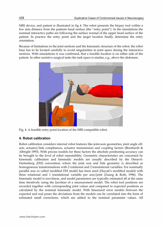
MRI device, and patient is illustrated in fig 4. The robot presents the biopsy tool within a few mm distance from the patients head surface (the “entry point”). In the simulations the nominal interactive paths are following the surface normal of the upper head surface of the patient. In practice the entry point and the target location finally determine the entry orientation.
Because of limitations in the joint motions and the kinematic structure of the robot, the robot base has to be located carefully to avoid singularities in joint space during the interactive motions. With simulations it was confirmed, that a feasible location is on either side of the patient. In other assistive surgical tasks the task space is similar, e.g., above the abdomen.
Fig. 4. A feasible entry point location of the MRI compatible robot.
4. Robot calibration
Robot calibration considers internal robot features like joint-axis geometries, joint angle off-sets, actuator/link compliances, actuator transmission and coupling factors (Bernhardt & Albright 1993). With precise models for these factors the absolute positioning accuracy can be brought to the level of robot repeatability. Geometric characteristics are concerned by kinematic calibration and kinematic models are usually described by the Denavit-Hartenberg (DH) convention, where the joint axis and link geometry is described as homogeneous transformations with 2 rotational and 2 translational variables. For nominally parallel axis so called modified DH model has been used (Hayati’s modified model) with three rotational and 1 translational variable per axis/joint (Zuang & Roth, 1996). The kinematic model is non-linear, and model parameters are typically estimated all at the same time iteratively using the Jacobian of a measurement model. The robot tool positions are recorded together with corresponding joint values and compared to expected positions as calculated by the nominal kinematic model. With linearized error models between the expected and real poses the deviations from the models can be correlated into the form of estimated small corrections, which are added to the nominal parameter values. All
www.intechopen.com
An Assistive Surgical MRI Compatible Robot – First Prototype with Field Tests
439
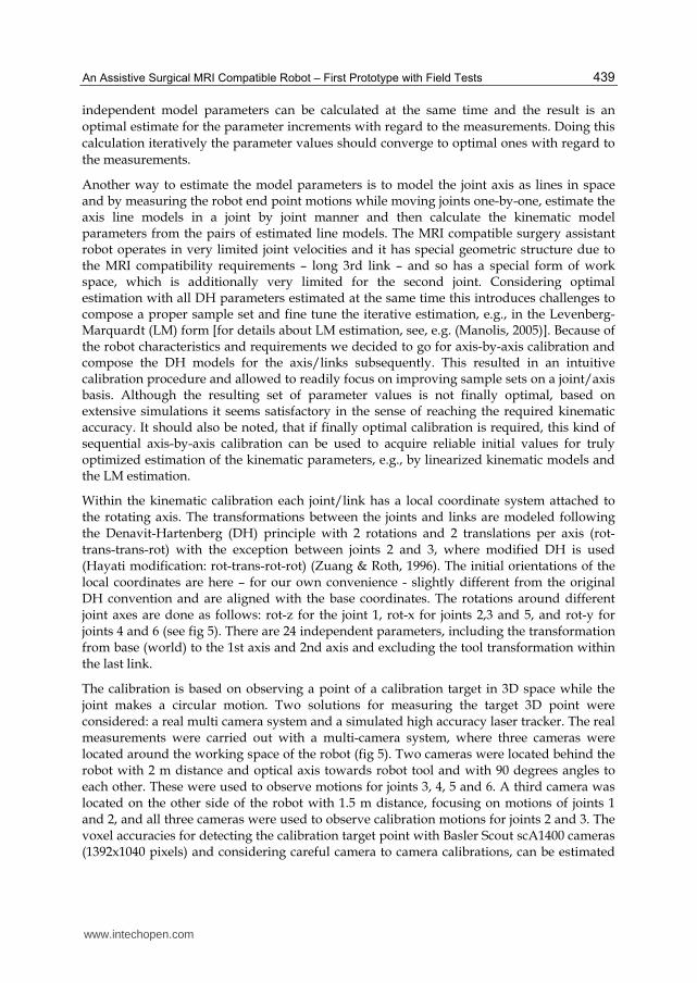
independent model parameters can be calculated at the same time and the result is an optimal estimate for the parameter increments with regard to the measurements. Doing this calculation iteratively the parameter values should converge to optimal ones with regard to the measurements.
Another way to estimate the model parameters is to model the joint axis as lines in space and by measuring the robot end point motions while moving joints one-by-one, estimate the axis line models in a joint by joint manner and then calculate the kinematic model parameters from the pairs of estimated line models. The MRI compatible surgery assistant robot operates in very limited joint velocities and it has special geometric structure due to the MRI compatibility requirements – long 3rd link – and so has a special form of work space, which is additionally very limited for the second joint. Considering optimal estimation with all DH parameters estimated at the same time this introduces challenges to compose a proper sample set and fine tune the iterative estimation, e.g., in the Levenberg-Marquardt (LM) form [for details about LM estimation, see, e.g. (Manolis, 2005)]. Because of the robot characteristics and requirements we decided to go for axis-by-axis calibration and compose the DH models for the axis/links subsequently. This resulted in an intuitive calibration procedure and allowed to readily focus on improving sample sets on a joint/axis basis. Although the resulting set of parameter values is not finally optimal, based on extensive simulations it seems satisfactory in the sense of reaching the required kinematic accuracy. It should also be noted, that if finally optimal calibration is required, this kind of sequential axis-by-axis calibration can be used to acquire reliable initial values for truly optimized estimation of the kinematic parameters, e.g., by linearized kinematic models and the LM estimation.
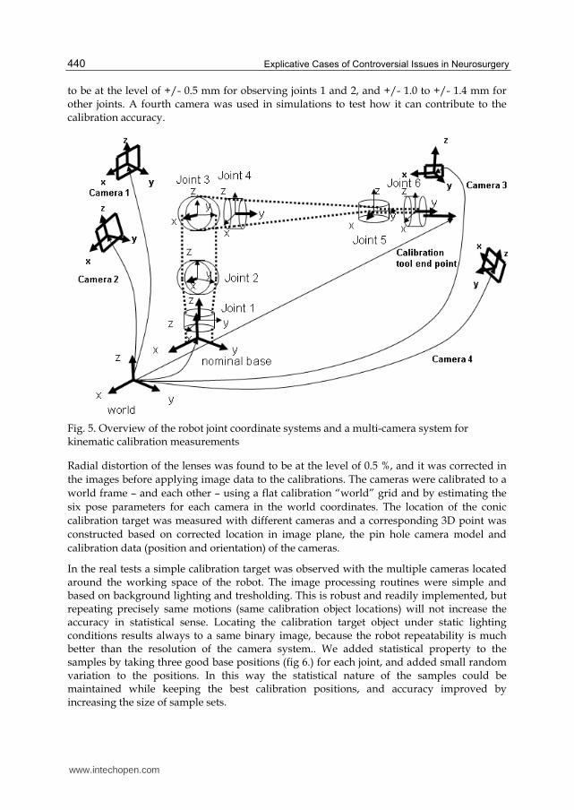
Within the kinematic calibration each joint/link has a local coordinate system attached to the rotating axis. The transformations between the joints and links are modeled following the Denavit-Hartenberg (DH) principle with 2 rotations and 2 translations per axis (rot-trans-trans-rot) with the exception between joints 2 and 3, where modified DH is used (Hayati modification: rot-trans-rot-rot) (Zuang & Roth, 1996). The initial orientations of the local coordinates are here – for our own convenience - slightly different from the original DH convention and are aligned with the base coordinates. The rotations around different joint axes are done as follows: rot-z for the joint 1, rot-x for joints 2,3 and 5, and rot-y for joints 4 and 6 (see fig 5). There are 24 independent parameters, including the transformation from base (world) to the 1st axis and 2nd axis and excluding the tool transformation within the last link.
The calibration is based on observing a point of a calibration target in 3D space while the joint makes a circular motion. Two solutions for measuring the target 3D point were considered: a real multi camera system and a simulated high accuracy laser tracker. The real measurements were carried out with a multi-camera system, where three cameras were located around the working space of the robot (fig 5). Two cameras were located behind the robot with 2 m distance and optical axis towards robot tool and with 90 degrees angles to each other. These were used to observe motions for joints 3, 4, 5 and 6. A third camera was located on the other side of the robot with 1.5 m distance, focusing on motions of joints 1 and 2, and all three cameras were used to observe calibration motions for joints 2 and 3. The voxel accuracies for detecting the calibration target point with Basler Scout scA1400 cameras (1392x1040 pixels) and considering careful camera to camera calibrations, can be estimated
www.intechopen.com
Explicative Cases of Controversial Issues in Neurosurgery
440
to be at the level of +/- 0.5 mm for observing joints 1 and 2, and +/- 1.0 to +/- 1.4 mm for other joints. A fourth camera was used in simulations to test how it can contribute to the calibration accuracy.
Fig. 5. Overview of the robot joint coordinate systems and a multi-camera system for kinematic calibration measurements
Radial distortion of the lenses was found to be at the level of 0.5 %, and it was corrected in the images before applying image data to the calibrations. The cameras were calibrated to a world frame – and each other – using a flat calibration “world” grid and by estimating the six pose parameters for each camera in the world coordinates. The location of the conic calibration target was measured with different cameras and a corresponding 3D point was constructed based on corrected location in image plane, the pin hole camera model and calibration data (position and orientation) of the cameras.
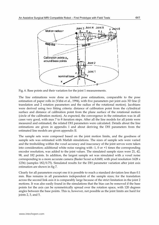
In the real tests a simple calibration target was observed with the multiple cameras located around the working space of the robot. The image processing routines were simple and based on background lighting and tresholding. This is robust and readily implemented, but repeating precisely same motions (same calibration object locations) will not increase the accuracy in statistical sense. Locating the calibration target object under static lighting conditions results always to a same binary image, because the robot repeatability is much better than the resolution of the camera system.. We added statistical property to the samples by taking three good base positions (fig 6.) for each joint, and added small random variation to the positions. In this way the statistical nature of the samples could be maintained while keeping the best calibration positions, and accuracy improved by increasing the size of sample sets.
www.intechopen.com
An Assistive Surgical MRI Compatible Robot – First Prototype with Field Tests
441
Fig. 6. Base points and their variation for the joint 1 measurements.
The line estimations were done as limited pose estimations, comparable to the pose estimation of paper rolls in (Vähä et al., 1994), with five parameters per joint axis 3D line (2 translation and 2 rotation parameters and the radius of the rotational motion). Jacobians were derived using two fitting criteria: distance of calibration point from the cylindrical surface and distance of calibration point from the plane surface of the rotational motion (circle of the calibration motion). As expected, the convergence in the estimation was in all cases very good, with max 7 to 8 iteration steps. After all the line models for all joints were measured and estimated, the related DH parameters were calculated. Details about the line estimations are given in appendix I and about deriving the DH parameters from the estimated line models are given appendix II.
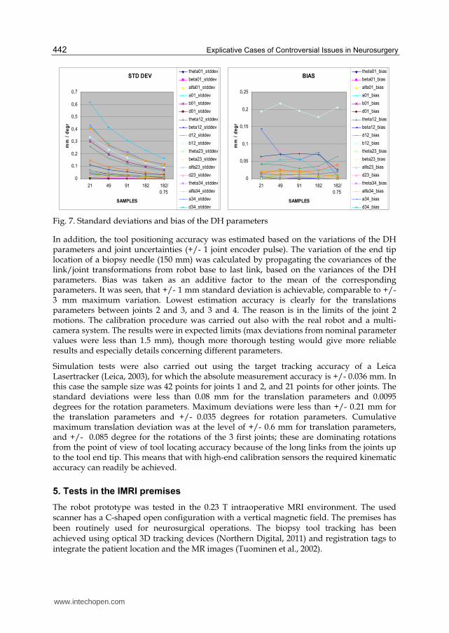
The sample sets were composed based on the joint motion limits, and the goodness of sample sets was estimated with Matlab simulations. The sizes of sample sets were varied and the tresholding within the voxel accuracy and inaccuracy of the joint servos were taken into consideration; additional white noise ranging with -1, 0 or +1 times the corresponding encoder resolution, was added to the joint values. The simulated sample sizes were 21, 42, 98, and 182 points. In addition, the largest sample set was simulated with a voxel noise corresponding to a more accurate camera (Basler Scout scA1600, with pixel resolution 1628 x 1236) (samples 182/0.75). Simulated results for the DH parameter variation after joint axis estimation are shown in fig 7.
Clearly for all parameters except one it is possible to reach a standard deviation less than 0.1 mm. Bias remains in all parameters independent of the sample sizes; for the translation across the second link axis it is comparably large because of the strict limitation in the joint 2 motions. It was also easily found in the simulations that the bias can be removed if the base points for the axis can be symmetrically spread over the rotation space, with 120 degrees angles between the base points. This is, however, not possible as the joint limits are hard for joints 2, 3, and 5.
www.intechopen.com
Explicative Cases of Controversial Issues in Neurosurgery
442
STD DEV
0
0,1
0,2
0,3
0,4
0,5
0,6
0,7
21 49 91 182 182/
0.75
SAMPLES
mm
/ d
eg
rtheta01_stddev
beta01_stddev
alfa01_stddev
a01_stddev
b01_stddev
d01_stddev
theta12_stddev
beta12_stddev
d12_stddev
b12_stddev
theta23_stddev
beta23_stddev
alfa23_stddev
d23_stddev
theta34_stddev
alfa34_stddev
a34_stddev
d34_stddev
BIAS
0
0,05
0,1
0,15
0,2
0,25
21 49 91 182 182/
0.75
SAMPLES
mm
/ d
eg
r
theta01_bias
beta01_bias
alfa01_bias
a01_bias
b01_bias
d01_bias
theta12_bias
beta12_bias
d12_bias
b12_bias
theta23_bias
beta23_bias
alfa23_bias
d23_bias
theta34_bias
alfa34_bias
a34_bias
d34_bias Fig. 7. Standard deviations and bias of the DH parameters
In addition, the tool positioning accuracy was estimated based on the variations of the DH parameters and joint uncertainties (+/- 1 joint encoder pulse). The variation of the end tip location of a biopsy needle (150 mm) was calculated by propagating the covariances of the link/joint transformations from robot base to last link, based on the variances of the DH parameters. Bias was taken as an additive factor to the mean of the corresponding parameters. It was seen, that +/- 1 mm standard deviation is achievable, comparable to +/- 3 mm maximum variation. Lowest estimation accuracy is clearly for the translations parameters between joints 2 and 3, and 3 and 4. The reason is in the limits of the joint 2 motions. The calibration procedure was carried out also with the real robot and a multi-camera system. The results were in expected limits (max deviations from nominal parameter values were less than 1.5 mm), though more thorough testing would give more reliable results and especially details concerning different parameters.
Simulation tests were also carried out using the target tracking accuracy of a Leica Lasertracker (Leica, 2003), for which the absolute measurement accuracy is +/- 0.036 mm. In this case the sample size was 42 points for joints 1 and 2, and 21 points for other joints. The standard deviations were less than 0.08 mm for the translation parameters and 0.0095 degrees for the rotation parameters. Maximum deviations were less than +/- 0.21 mm for the translation parameters and +/- 0.035 degrees for rotation parameters. Cumulative maximum translation deviation was at the level of +/- 0.6 mm for translation parameters, and +/- 0.085 degree for the rotations of the 3 first joints; these are dominating rotations from the point of view of tool locating accuracy because of the long links from the joints up to the tool end tip. This means that with high-end calibration sensors the required kinematic accuracy can readily be achieved.
5. Tests in the IMRI premises
The robot prototype was tested in the 0.23 T intraoperative MRI environment. The used scanner has a C-shaped open configuration with a vertical magnetic field. The premises has been routinely used for neurosurgical operations. The biopsy tool tracking has been achieved using optical 3D tracking devices (Northern Digital, 2011) and registration tags to integrate the patient location and the MR images (Tuominen et al., 2002).
www.intechopen.com
An Assistive Surgical MRI Compatible Robot – First Prototype with Field Tests
443
The prototype was fixed to a floor worktop which was set over two props for the tests. Using this arrangement the prototype could be moved to desired points around the scanner. The tests had the following endpoints:
1. Test functionality of the prototype in the magnetic field. 2. Test MR safety and compatibility of the prototype, and 3. Test capability of the robot to move a biopsy needle guide to the correct configuration
to allow the surgeon to pass a biopsy needle through the guide to a target
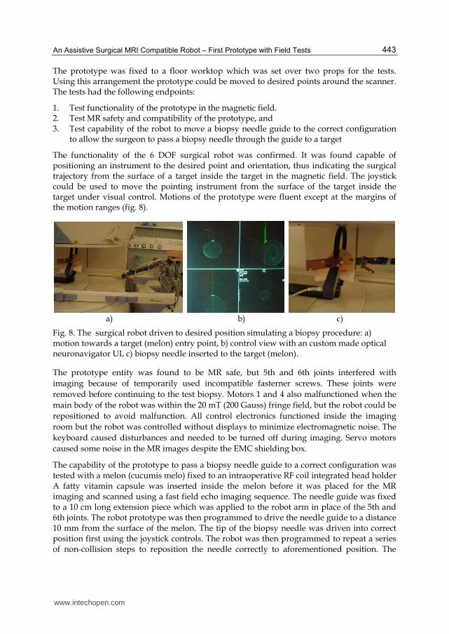
The functionality of the 6 DOF surgical robot was confirmed. It was found capable of positioning an instrument to the desired point and orientation, thus indicating the surgical trajectory from the surface of a target inside the target in the magnetic field. The joystick could be used to move the pointing instrument from the surface of the target inside the target under visual control. Motions of the prototype were fluent except at the margins of the motion ranges (fig. 8).
a) b) c)
Fig. 8. The surgical robot driven to desired position simulating a biopsy procedure: a) motion towards a target (melon) entry point, b) control view with an custom made optical neuronavigator UI, c) biopsy needle inserted to the target (melon).
The prototype entity was found to be MR safe, but 5th and 6th joints interfered with imaging because of temporarily used incompatible fasterner screws. These joints were removed before continuing to the test biopsy. Motors 1 and 4 also malfunctioned when the main body of the robot was within the 20 mT (200 Gauss) fringe field, but the robot could be repositioned to avoid malfunction. All control electronics functioned inside the imaging room but the robot was controlled without displays to minimize electromagnetic noise. The keyboard caused disturbances and needed to be turned off during imaging. Servo motors caused some noise in the MR images despite the EMC shielding box.
The capability of the prototype to pass a biopsy needle guide to a correct configuration was tested with a melon (cucumis melo) fixed to an intraoperative RF coil integrated head holder A fatty vitamin capsule was inserted inside the melon before it was placed for the MR imaging and scanned using a fast field echo imaging sequence. The needle guide was fixed to a 10 cm long extension piece which was applied to the robot arm in place of the 5th and 6th joints. The robot prototype was then programmed to drive the needle guide to a distance 10 mm from the surface of the melon. The tip of the biopsy needle was driven into correct position first using the joystick controls. The robot was then programmed to repeat a series of non-collision steps to reposition the needle correctly to aforementioned position. The
www.intechopen.com
Explicative Cases of Controversial Issues in Neurosurgery
444
actual biopsy procedure was then simulated by passing the biopsy needle by hand through the guide until the tip of the needle hit the vitamin capsule inside the melon. A tag of the optical tool tracking system was connected to the biopsy needle and the tool tracking was used to guide and verify the insertion successfully, including the entry and final locations of the needle tip inside the melon (fig 8 b).
6. Discussion
A working readily maneuverable robot prototype has been constructed. The working space is generally limited, but suitable for IMRI related operations in the region of surgical interest. Motion control based on the RCCL library was quick to implement and was easily used as far as robots paths needed to be programmed. Because the Cartesian speed of a tool (e.g., a biopsy needle) can be very low (ca. 5 cm / sec), the feasibility of joint trajectories has been achieved in test runs.
The kinematic calibration was carried out in a simple and straightforward way. The limitations of joints, especially for joint 2, clearly caused the largest estimation uncertainties in the related DH parameters. Based on simulations the required accuracy is still achievable if the laser tracker is used for tracking the calibration target. A multi camera system can be used as well, but usability with the ordinary cameras we have been using is limited for cross checking the kinematic parameter values. Still, for interactive control of fine motions with tight integration of the surgeon this is enough. For more advanced automatic motion control the remaining uncertainties would require laser tracker based calibration.
From the presented ROSI principle it follows, that the surgical guidance device must be optimized for functionality in the volume of the ROSI, which in neurosurgery means that of the human head. This involves dividing the tasks of the robot into gross and local movements. This was achieved in the present tests by robotic movement of the needle guide to a predetermined position 10 mm from the target followed by manual passage of the needle to the target.
The longer term goal is to integrate the robot and its usage tighter with MR images. This will lead to integration of the MRI device with respect to the robot coordinate system and then using the same technology for tracking the tool attached to the robot end tip. This will substantially loosen the accuracy requirements of the robot: global accuracy will be taken care by the optical tracking tool [currently at the level of +/- 0.7 mm (Katisko, 2007)] after which local accuracy of the robot becomes critical, just like in the case of interactive control. It is also noteworthy that there are varying IMRI practices for imaging and operating, e.g., the following (Yrjänä, 2005):
- Imager lowered for surgery - Surgery in fringe field - Surgery in adjacent Operation Room - Magnetic field turned off for surgery - Surgery in imaging space - Surgery adjacent to the imaging space - Imager moved away for surgery
www.intechopen.com
An Assistive Surgical MRI Compatible Robot – First Prototype with Field Tests
445
Depending on the case, the requirements for the robot may vary quite much. We have reached the level of a prototype principally compatible with the IMRI premises and optimized for the ROSI. However, the varying imaging and operating practices create challenges for deciding the next stages of development.
The present robot project was a logical continuation in our research community of early experience with the development of neuronavigation based on a 6 DOF passive mechatronic arm (Koivukangas et al., 1993a, b). This device was routinely clinically used for image-guided procedures, guiding a variety of instruments in the same way as optical tracking systems. The mechatronic arm had joints that were designed to house both electromagnetic clutch brakes and servo motors.
The rationale for developing an active robot arose from the need to transfer the result of presurgical planning directly to the surgical field, like by the Robodoc (Bargar et. al. 1998), which can be preprogrammed to create an optimal boney fit for prostheses in hip and knee replacement surgery. From the other reported IMRI developments the present robot differs in that it was specified to perform safe preprogrammed movement of a needle guide to the target in the region of surgical interest and to act as a stative, or needle guide holder, while the surgeon passes the biopsy needle or forceps to the target--all of this in the magnetic field of an IMRI scanner. It was a necessary first step to confirm the functionality and accuracy of our robotic solution. With continued experience in both robotics and image-guided surgery, our group plans on extending the functionality of the robot.
7. Conclusions
A prototype robot for assisting surgery operations in IMRI environments was described in this paper. We reported on the robot to repeatedly perform a preprogrammed exercise in the magnetic field of an IMRI scanner in a safe noncollision manner. The target was a fatty vitamin pill placed inside a melon. The robot brought the end effector into the region of surgical interest and positioned the tip of the needle guide holder 10 mm from the object, serving as a stereotactic device to enable the passage of the biopsy instrument to its exact final target.
The mechatronic structure, calibration and experimental tests in an IMRI environment were explained in more details. Simulations showed that expected locating accuracy from the point of view of joint sensors and calibrations sensors can be achieved. The robot could be operated in a semiautomatic manner, either running paths or interactively using joystick, in joint space or Cartesian space. Field tests in the hospital IMRI unit confirmed the applicability of the system in the region of surgical interest even under MRI conditions.
8. Appendix I: Estimation of the axis as a line in space
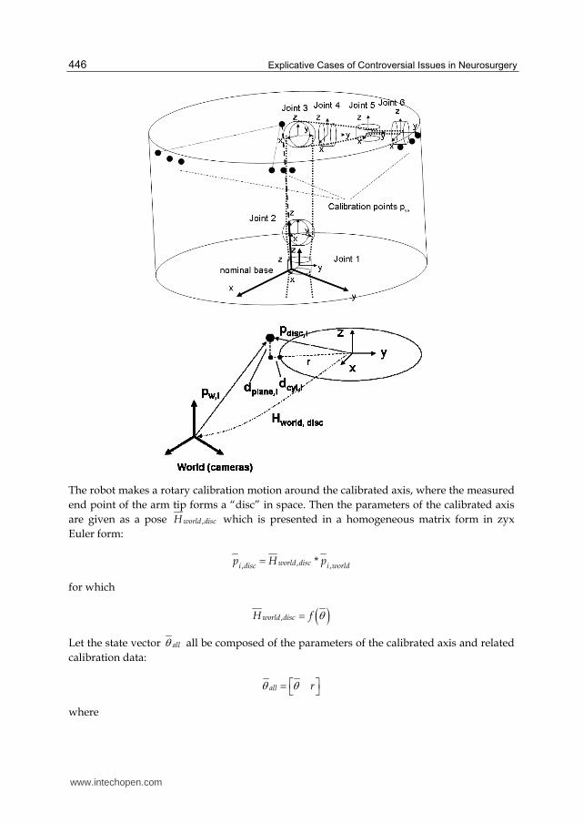
The calibration is carried out in a joint by joint manner. Each joint is moved one by one, and the end tip 3D coordinates of the calibration object is recorded in world frame. For each joint motion a 3D line model of the joint is calculated, which results to six 3D line models in the world frame. From these line models the DH parameters are further calculated.
www.intechopen.com
Explicative Cases of Controversial Issues in Neurosurgery
446
The robot makes a rotary calibration motion around the calibrated axis, where the measured end point of the arm tip forms a “disc” in space. Then the parameters of the calibrated axis are given as a pose ,world discH which is presented in a homogeneous matrix form in zyx Euler form:
,, ,*world disci disc i worldp H p
for which
,world discH f
Let the state vector all all be composed of the parameters of the calibrated axis and related calibration data:
all r
where
www.intechopen.com

An Assistive Surgical MRI Compatible Robot – First Prototype with Field Tests
447
θ is the vector of pose parameters and, r is the radius of the rotation “disc”, i.e., around the axis.
The pose parameters of the “disc” are then
Tx y z
where ┙ is rotation around x axis, ┚ is rotation around y axis χ is rotation around z axis, here undefined, x is x coordinate, y is y coordinate, z is z coordinate,
We have nominal values for the “disc” pose parameters, to which the measured 3D points are matched. Because the rotational part of the “disc” pose are non-linear, we define two error measures, related to which we linearize the measurement model.
Let the error measure for point i be
,
,
plane i
icyl i
de
d
where ,plane id is distance from the measured point to the disc plane and
,cyl id is distance from the measured point to the cylindrical surface set by the disc
The nominal disc location is always in origin, so the distance from the measured point to the disc plane is the z coordinate of the measured point in the disc pose:
,plane disc zd p
The distance from the cylindrical surface of the disc is in a similar way
2 2, , , ,cyl s disc x s disc yd p p r
Now we derive the linear relationship between the error measure and the state parameters:
* disc
disc
pe e
p
for which
, 0 0 1plane disc z
disc disc
d p
p p
and
www.intechopen.com

Explicative Cases of Controversial Issues in Neurosurgery
448
,,
2 2 2 2, , , , , , , ,
0cyl disc ydisc x
disc s disc x s disc y s disc x s disc y
d pp
p p p p p
The partial derivatives of the measured point in the disc pose are
, ,
, ,
, ,
0 1 0 0
0 0 1 0
0 0 0 1
disc z disc y
discdisc z disc x
disc y disc x
p pp
p p
p p
The 3rd column will be omitted, because the rotation around the calibrated axis, i.e., around the z-axis of the disc pose cannot be estimated.
For the radius of the disc we get
1cyld
r
Finally the estimate the parameter increments for the updated 6 parameters (rotation around z axis omitted):
1
* * *T Tx
J J J ey
z
r
where the Jacobian
eJ
The complete estimation algorithm is as follows:
0. set initial disc pose and radius 1. calculate nominal calibration point positions in disc frame 2. calculate error measures for each calibration point 3. calculate the Jacobian, i.e., the partial derivatives 6. calculate parameters increments for the state parameters 7. update the state parameters 8. if increments not 'small enough', go to 1, otherwise end.
9. Appendix II: From line models to DH parameters
Measured axis lines are given as an arbitrary point in the line pi and a normalized direction vector ni. From a pair of these the DH parameters or modified DH parameters will be derived.
www.intechopen.com
An Assistive Surgical MRI Compatible Robot – First Prototype with Field Tests
449
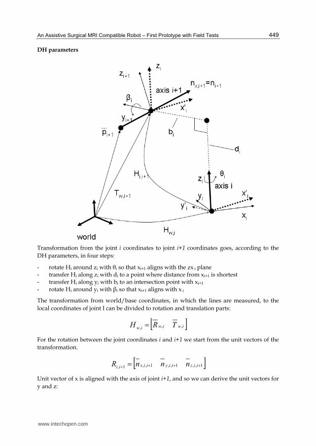
DH parameters
Transformation from the joint i coordinates to joint i+1 coordinates goes, according to the DH parameters, in four steps:
- rotate Hi around zi with θi so that xi+1 aligns with the zx i plane - transfer Hi along zi with di to a point where distance from xi+1 is shortest - transfer Hi along yi with bi to an intersection point with xi+1 - rotate Hi around yi with βi so that xi+1 aligns with x i
The transformation from world/base coordinates, in which the lines are measured, to the local coordinates of joint I can be divided to rotation and translation parts: iwiwiw TRH ,,,
For the rotation between the joint coordinates i and i+1 we start from the unit vectors of the transformation. 1,,1,,1,,1, iiziiyiixii nnnR
Unit vector of x is aligned with the axis of joint i+1, and so we can derive the unit vectors for y and z:
www.intechopen.com

Explicative Cases of Controversial Issues in Neurosurgery
450
1,,
1,,1,
ixiz
ixiziy
nn
nnn
1,1,1, iyixiz nnn
Axis of joint i+1, i.e., nx,i+1 in joint i coordinates is then
1,
1
,,1, *
ixiwiix nHn
and as coordinates
iixn
iixn
iixn
iix
z
y
x
n
,1,,
,1,,
,1,,'
,1,
Then we get for the angle θi
)tan(,1,,
,1,,
iixn
iixn
ix
ya
and for the angle ┚i
)sin( ,1,, iixni za
For the translation in direction of yi,i+1 we get the same as the distance bi between the axis i and axis i+1:
The point of axis i+1 after rotation by θi as Hi,θ
1000
0100
00)cos()sin(
00)sin()cos(
,
iH
and
1,,1
1
,
1
,1,,1**
iwiiwiipHHp
Then we get
yiii pb ,1,
www.intechopen.com
An Assistive Surgical MRI Compatible Robot – First Prototype with Field Tests
451
Axis i+1 is located in the direction of the rotated xz plane, with the distance of bi from this plane. The point in axis i+1 which is closest to axis i is also located in rotated yz plane. From point p this closest point locates to the direction of xi+1 with the following coefficient
1,,
,1,
iix
xii
n
pk
and then the point gets the z coordinate and also the translation along the z-axis of Hw,i as
, 1, , 1*i i i z nxi id p k z
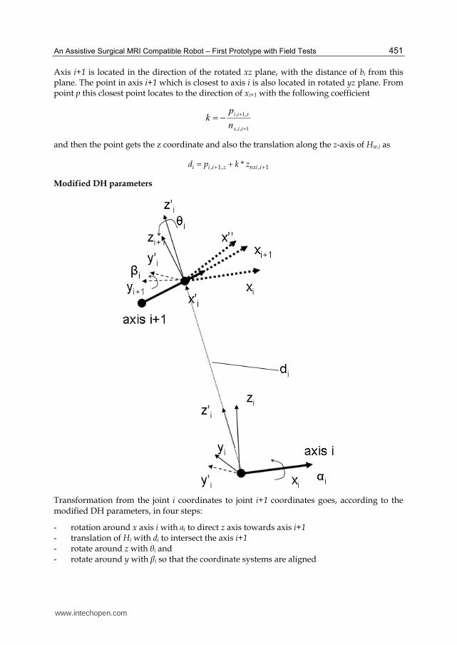
Modified DH parameters
Transformation from the joint i coordinates to joint i+1 coordinates goes, according to the modified DH parameters, in four steps:
- rotation around x axis i with ┙i to direct z axis towards axis i+1 - translation of Hi with di to intersect the axis i+1 - rotate around z with θi and - rotate around y with ┚i so that the coordinate systems are aligned
www.intechopen.com

Explicative Cases of Controversial Issues in Neurosurgery
452
The distance of the point of axis i+1 in the zy plane of the frame Hi is the x coordinate of point pi+1 in the axis i+1. The intersection point of the axis i+1 with the zy plane – and the origin of the frame Hi+1 becomes then
iwiwiw TRH ,,,
For the translation between the joint coordinate systems we get
1,
,1,
,1,
1,1, *
ii
xii
xii
iiii nn
ppT
and the rotation angle ┙i becomes then
zii
yii
iiT
Ta
,1,
,1,
1, tan
The link transformation after rotation ┙i becomes then
1000
)cos()sin(0
)sin()cos(0
001
,1,
,1,
,1,
,
zii
yii
xii
i
T
T
T
H
and further
1000
1,,1,,
iiiii
TRH
where ,1,,,1,,,1,,,1, iiziiyiixii nnnR
For the y and z axis for the frame Hi+1 we get then
1,,1,,
1,,1,,1,
ixiiz
ixiiziy
nn
nnn
1,1,1, iyixiz nnn
The direction vector of the axis i+1 becomes after the rotation ┙i around x axis i
1,
1
,,1,,1 *
iiiaii nHn
www.intechopen.com

An Assistive Surgical MRI Compatible Robot – First Prototype with Field Tests
453
The rotation angle θi around z axis is then
xii
yii
iin
na
,,1,
,,1,
1, tan
The link transformation after rotation θi becomes then
iii HHH ,,,, *
where
1000
0100
00)cos()sin(
00)sin()cos(
,
iH
The transformation can be given also with the rotation and translation parts
1000
1,,,,1,,,
iiiiii
TRH
where ,,1,,,,1,,,,1,,,,1, iiziiyiixii nnnR
Finally the rotation angle ┚i around y axis is
xii
zii
iin
na
,,,1,
,,,1,
1, tan
10. Acknowledgements
The Oulu medical robotics community has over 20 years of experience in the field of medical applications, and some earlier contributions of it are also referred to in the text. The authors would like to acknowledge many colleagues who contributed to the realization of the robot prototype: Yrjö Louhisalmi LicTech (ME), Prof. Kalervo Nevala PhD (ME), Jani Virtanen PhD, Jani Katisko LicTech (biophysics), Pekka Isto PhD, Tapani Koivukangas MS (ME), Pirkka Tukeva MS (ME), Matti Annala engineer, and Jari Hämeenaho technician.
11. References
Bargar W. L., Bauer A., Börner M. Primary and revision total hip replacement using the Robodoc system. Clin Orthop Relat Res. 1998, Sep;(354):82-91.
Bernhardt R. & Albright S. (1993). Introduction. In Bernhardt R., Albright S (eds.): Robot
Calibration, Chapman & Hall, Cambridge 1993, 311 p.
www.intechopen.com
Explicative Cases of Controversial Issues in Neurosurgery
454
Castillo-Cruces R. & Wahrburg J. (2010). Virtual fixtures with autonomous error compensation for human-robot cooperative tasks. Robotica (2010) Vol 28, 2, pp. 267-277.
Chinzei K. & Miller K. (2001). MRI guided surgical robot, In: Proceedings of the Australian
Conference of Robotics and Automation, Sydney 2001, pp. 50–55. Chinzei K., Hata N., Jolesz F.A., Kikinis R. (2000). MR Compatible Surgical Assist Robot:
System Integration and Preliminary Feasibility Study. In: Proceedings of the 3rd
International Conferece of Medical Image Computing and Computer-Assisted Intervention, Pittsburg, Pennsylvenia, USA, 11-14 October. 2000; pp. 921-930.
Cleary K. & Nguyen C. (2001). State of the Art in Surgical Robotics: Clinical Applications and Technology Challenges. Computer Aided Surgery, November 2001. 26p
Dasgupta P., Henderson A., (2010). Robotic urological surgery. Robotica (2010) Vol 28, pp. 235-240.
Elhawary H., Zivanovic A., Davies B. & Lamperth M. (2005), A review of magnetic resonance imaging compatible manipulators in surgery. Proceedings of IMechE, Vol. 220 Part H: Journal of Engineering in Medicine, pp. 413 - 424.
Gasparetto A., Zanotto V. (2010). Toward an optimal performance index for neurosurgical robot’s design. Robotica (2010) Vol 28, pp. 279-296
Gassert R., Burdet E, & Chinzei K. (2008). MRI-Compatible Robotics. A Critical Tool for Image-Guided Interventions, Clinical Diagnostics, and Neuroscience. IEEE
Engineering in in Medicine and Biology Magazine, May/June 2008, pp. 12 – 14. Harja J., Tikkanen J., Sorvoja H. & Myllylä, R. (2007). Magnetic resonance imaging-
compatible, three-degrees-of-freedom joystick for surgical robot. The International
Journal of Medical Robotics and Computer Assisted Surgery, Vol.3, Issue 4, (December 2007), 7 p.
Heikkilä T., Isto P., Järviluoma M., Kilpeläinen P., Sallinen M. (2009). A Prototype for an Assistive Surgical MRI Compatible Robot. The 14th IASTED International Conference
on Robotics and Applications - RA 2009. November 4 – 6, 2009, Cambridge, Massachusetts, USA.
Jaara J. (2007). Designing surgical robot for clinical robot for MR-imaging environment. Diploma thesis, University of Oulu (in finnish). 60p + 12p appendixes.
Katisko J & Koivukangas J (2007) Optically neuronavigated ultrasonography in an intraoperative magnetic resonance imaging environment. Neurosurgery 60(4 Suppl 2): 373–381.
Koivukangas J., Louhisalmi Y., Alakuijala J., Oikarinen J. (1993a) Ultrasound-controlled neuronavigator-guided brain surgery. J Neurosurg 79: 36-42.
Koivukangas J., Louhisalmi Y., Alakuijala J., Oikarinen J. (1993b) Neuronavigator-guided cerebral biopsy. Acta Neurochir Suppl 58: 71-74.
Koivukangas J, Katisko J, Yrjänä S, Tuominen J, Schiffbauer H, Ilkko E (2003) Successful neurosurgical 0.23T intraoperative MRI in a shared facility. Neurosurgery 2003. Monduzzi Editore Medimond: 439-444.
Larson B. T., Erdman A. G., Tsekos N. V., Yacoub E., Tsekos P. V. & Koutlas I. G. (2004). Design of an MRI-compatible robotic stereotactic device for minimally invasive
www.intechopen.com
An Assistive Surgical MRI Compatible Robot – First Prototype with Field Tests
455
interventions in the breast, Journal of Biomechanical Engineering, vol. 126, pp. 458–465.
Leica Geosystems (2003). Leica Absolute TrackerTM With PowerLock Active Vision Technology. Available from http://www.leica-geosystems.com/en/Laser-Tracker-Systems-Leica-Absolute-Tracker_69047.htm
Manolis I. (2005). A. A brief description of the Levenberg-Marquardt algorithm implemented by levmar. Foundation for research and technology, Heraklion, 2005.
Masamune, K., Kobayashi E., Masutani Y., Suzuki M., Dohi T., Iseki H. & Takakura K.(1995). Development of an MRI-compatible needle insertion manipulator for stereotactic neurosurgery. Journal of Image Guided Surgery, vol. 1, pp. 242–248.
Northern Digital Inc. (2011). Polaris Family of Optical Tracking Systems. Available from: http://www.ndigital.com/medical/polarisfamily.php
Ojala, R. (2002). MR-guided interventions at 0.23T. Facilities, user interface, guiding technology
and musculoskeletal applications. PhD Thesis, University of Oulu, 73 p. Pandya S., Motkoski J. W., Serrano-Almeida C., Greer A. D., Latour I., Sutherland G. R.,
Advancing Neurosurgery with Image-Guided Robotics. Journal of Neurosurgery 111:1141-1149, 2009.
Philips, Panorama 0.23T R/T Manufacturer Specifications (2011). Available from http://www.medwow.com/med/mri/philips/panorama-0-23t-r-t/28837.model-spec
Plante J-S., Lauren M., DeVita K., Kacher D., Roebuck J., DiMaio S., Jolesz F. & Dubowsky S. An MRI-Compatible Needle Manipulator Concept Based on Elastically Averaged Dielectric Elastomer Actuators for Prostate Cancer Treatment: An Accuracy and MR-Compatibility Evaluation in Phantoms. Journal of Medical Devices, Sep. 2009, Vol 3. 10p.
Stein, M. (2004). RWRCCL: A New RCCL Implementation Using Real-Time Linux And A
Single CPU. Available from: http://faculty.rwu.edu/mstein/verbiage/RWRCCL.pdf Susil R. C., Krieger A., Derbyshire J. A., Tanacs A., Whitcomb L. L., Fichtinger G. & Atalar E.
(2003). System for MR image-guided prostate interventions: Canine study, Radiology, vol. 228, pp. 886–894.
Tsekos N. V., Ozcan A. & Christoforou E. (2005). A prototype manipulator for MR-guided interventions inside standard cylindrical MRI scanners. Journal of Biomechanical
Engineering, vol. 127, pp. 972–980. Tsekos N., Christoforou E. & Özcan, A. (2008). A General-Purpose MR-Compatible
Robotic System - Implementation and Image Guidance for Performing Minimally Invasive Interventions. IEEE in Engineering and Biology Magazine, May/June 2008, pp. 51 - 58.
Tuominen, J., Yrjänä S. K., Katisko J. P., Heikkilä J., Koivukangas J (2002) Intraoperative imaging in a comprehensive neuronavigation environment for minimally invasive brain tumor surgery. Acta Neurochir Suppl 85: 115-120.
Virtanen, J. (2006). Enhancing the compatibility of surgical robots with magnetic resonance
imaging. PhD Thesis, University of Oulu, 2006. 196 p.
www.intechopen.com

Explicative Cases of Controversial Issues in Neurosurgery
456
Virtanen, J. & Nevala, K. (2007). MR- compatibility of an intraoperative robot. 12th IFToMM
Word Congress, Besancon, France, June 18-21, 2007. 6 p. Vähä P., Heikkilä T., Röning J. & Okkonen J. (1994). Machine of the Future: An Intelligent
Paper Roll Manipulator. Mechatronics, Vol. 4, No. 8, pp. 861 - 877. Yrjänä S. (2005). Implementation of 0.23 T magnetic resonance scanner to perioperative imaging in
neurosurgery. PhD Thesis, University Of Oulu, 2005, 71 p. Zhijiang D., Lining S. Review of Surgical Robotics and Key Technologies Analysis. In:
Proceedings of the IEEE International Conference on Robotics, Intelligent Systems and
Signal Processing. Changsha, China, October 2003, pp. 1041 – 1046. Zoppi M., Khan M., Schäfer F., Molfino R. (2010). Toward lean minimally invasive robotic
surgery. Robotica (2010) Vol 28, pp. 185-197. Zuang H. & Roth Z. (1996). Camera-Aided Robot Calibration. CRC Press Inc., Florida, USA,
1996, 353 p.
www.intechopen.com

Explicative Cases of Controversial Issues in NeurosurgeryEdited by Dr. Francesco Signorelli
ISBN 978-953-51-0623-4Hard cover, 534 pagesPublisher InTechPublished online 23, May, 2012Published in print edition May, 2012
InTech EuropeUniversity Campus STeP Ri Slavka Krautzeka 83/A 51000 Rijeka, Croatia Phone: +385 (51) 770 447 Fax: +385 (51) 686 166www.intechopen.com
InTech ChinaUnit 405, Office Block, Hotel Equatorial Shanghai No.65, Yan An Road (West), Shanghai, 200040, China
Phone: +86-21-62489820 Fax: +86-21-62489821
Neurosurgery is a rapidly developing field of medicine. Therefore, staying keeping track of the advancementsin the field is paramount for trainees as well as fully trained neurosurgeons. This book, fully available online, isa part of our effort of improving availability of medical information for anyone who needs to keep up-to-date.
How to referenceIn order to correctly reference this scholarly work, feel free to copy and paste the following:
Tapio Heikkilä, Sanna Yrjänä, Pekka Kilpeläinen, John Koivukangas and Mikko Sallinen (2012). An AssistiveSurgical MRI Compatible Robot - First Prototype with Field Tests, Explicative Cases of Controversial Issues inNeurosurgery, Dr. Francesco Signorelli (Ed.), ISBN: 978-953-51-0623-4, InTech, Available from:http://www.intechopen.com/books/explicative-cases-of-controversial-issues-in-neurosurgery/an-assistive-surgical-mri-compatible-robot-first-prototype-with-field-tests

© 2012 The Author(s). Licensee IntechOpen. This is an open access articledistributed under the terms of the Creative Commons Attribution 3.0License, which permits unrestricted use, distribution, and reproduction inany medium, provided the original work is properly cited.


![Assistive Planning in Complex, Dynamic Environments: a ... · of use cases: assistive wheelchair technology [12], assistive au-tomobile driving, and assistive manufacturing vehicle](https://static.fdocuments.net/doc/165x107/6055985ff7e719060567e863/assistive-planning-in-complex-dynamic-environments-a-of-use-cases-assistive.jpg)