An Approach to Implementing Cloud Service Oriented Legacy ...€¦ · an analysis approach to...
213
An Approach to Implementing Cloud Service Oriented Legacy Application Evolution Ph.D Thesis Shang Zheng Software Technology Research Laboratory De Montfort University 2013
Transcript of An Approach to Implementing Cloud Service Oriented Legacy ...€¦ · an analysis approach to...
An Approach to Implementing Cloud Service
Oriented Legacy Application Evolution
Ph.D Thesis
Shang Zheng
Software Technology Research Laboratory
De Montfort University
2013
i
To my parents, Xiaoling Zheng and Shuping Yu,
for their love and support.

Declaration
ii
Declaration
I declare that the work described in this thesis was originally carried out by me during
the period of registration for the degree of Doctor of Philosophy at De Montfort
University, UK from October 2009 to May 2013. Apart from the degree that this thesis
is currently applying for, no other academic degree or award was applied for me based
on this work.
Acknowledgements
iii
Acknowledgements
I would like to thank everyone who has helped me in different ways with the
development of this thesis.
First, I would like to express my profound thanks to my first supervisor Prof. Hongji
Yang, who has given me enormous support, guidance and encouragement during these
years‘ study. He provided me with many useful suggestions for the thesis.
Secondly, I need to thank my second supervisor Dr. Feng Chen, for his helpful
comments and support on the three years‘ study and the final thesis.
Thirdly, I also want to thank the colleagues at De Montfort University, Dr. Helge
Janicke, Dr. Yang Xu, Dr. Jianzhi Li, Dr. Jiantao Zhou, Dr. Yanmei Huo and many
others. It has been very fortunate for me to work and study with them.
Finally, I wish express thanks to my parents for their love, encouragement, patience and
support over the past years. This thesis is dedicated to them.
Abstract
iv
Abstract
An emerging IT delivery model, Cloud Computing, can significantly reduce IT costs
and complexities while improving workload optimisation and service delivery. More
and more organisations are planning to migrate their existing systems into this
internet-driven computing environment. This investigation is proposed for this purpose
and will be undertaken with two main aims. The first aim is to establish a general
framework and method to assist with the evolution of legacy systems into and within
the Cloud environment. The second aim is to evaluate the proposed approach and
demonstrate that such an approach can be more effective than develop ing Cloud
services from scratch.
The underlying research procedure of this thesis consists of observation, proposition,
test and conclusion. This thesis contributes a novel evolution approach in Cloud
computing. A technical solution framework is proposed through a three-dimensional
software evolution paradigm, which can cover the relationships of software models,
software functions and software qualities in different Cloud paradigms. Finally, the
evolved service will be run in the Cloud environments. The approach framework is
implemented by three phases: 1) legacy system analysis and extraction, which proposes
an analysis approach to decide the legacy system in the Cloud environment and to adopt
the techniques of program slicing with improved algorithm and software clustering for
extracting legacy components. 2) Cloud-oriented service migration including evolving
software into and within Cloud. The process of evolving software ―INTO‖ Cloud can be
viewed mainly as changing software qualities on software models. The process of
evolving software ―WITHIN‖ Cloud can be viewed mainly as changing software
functions on software models, the techniques of program and model transformation and
software architecture engineering are applied. 3) Cloud service integration, which
integrates and deploys the service in the Cloud environment.
The proposed approach is proved to be flexible and practical by the selected case study.
Conclusions based on analysis and future research are discussed at the end of the thesis.
Table of Contents
v
Table of Contents
Declaration ................................................................................................................................................................... ii
Acknowledgements.................................................................................................................................................... iii
Abstract........................................................................................................................................................................ iv
Table of Contents ....................................................................................................................................................... v
List of Figures............................................................................................................................................................. ix
List of Tables .............................................................................................................................................................. xi
List of Acronyms .....................................................................................................................................................xiii
Chapter 1 Introduction ...................................................................................................................................... 1
1.1 Background.................................................................................................................................................... 1
1.2 Problem Statement ....................................................................................................................................... 2
1.3 Research Objectives and Research Methods ........................................................................................... 4
1.4 Research Questions and Hypotheses......................................................................................................... 6
1.4.1 Research Questions ........................................................................................................................... 6
1.4.2 Research Hypotheses......................................................................................................................... 7
1.5 Original Contributions ................................................................................................................................. 7
1.6 Success Criteria ............................................................................................................................................. 8
1.7 Organisation of Thesis ................................................................................................................................. 9
Chapter 2 Literature Review .......................................................................................................................... 11
2.1 Overview...................................................................................................................................................... 11
2.2 Software Engineering ................................................................................................................................ 12
2.3 Software Evolution and Software Reengineering ................................................................................. 14
2.3.1 Software Maintenance..................................................................................................................... 14
2.3.2 Software Evolution .......................................................................................................................... 14
2.3.3 Software Reengineering.................................................................................................................. 18
2.4 Requirement Engineering.......................................................................................................................... 19
2.4.1 Requirements .................................................................................................................................... 19
2.4.2 Requirements Engineering Challenges ........................................................................................ 21
2.5 Software Architecture ................................................................................................................................ 22
2.5.1 Software Architecture Styles .......................................................................................................... 22
2.5.2 Model Driven Architecture............................................................................................................. 24

Table of Contents
vi
2.6 Computing Paradigm ................................................................................................................................. 25
2.6.1 Grid Computing ............................................................................................................................... 25
2.6.2 Internetware...................................................................................................................................... 25
2.6.3 Cloud Computing ............................................................................................................................. 26
2.7 Legacy System Decomposition................................................................................................................ 28
2.7.1 Legacy System .................................................................................................................................. 29
2.7.2 Program Slicing ............................................................................................................................... 31
2.7.3 Software Clustering ......................................................................................................................... 32
2.7.4 Wrapping Technique ....................................................................................................................... 33
2.8 Software Evolution Approaches .............................................................................................................. 33
2.8.1 Service-Oriented Software Evolution ........................................................................................... 33
2.8.2 Requirement-Oriented Software Evolution ................................................................................. 35
2.8.3 Grid-Oriented Software Evolution................................................................................................ 36
2.8.4 Cloud-Oriented Software Evolution ............................................................................................. 37
2.8.5 Evolution Assistant .......................................................................................................................... 39
2.9 Summary ...................................................................................................................................................... 41
Chapter 3 Proposed Framework ................................................................................................................... 44
3.1 Overview...................................................................................................................................................... 44
3.2 The Proposed Framework ......................................................................................................................... 45
3.2.1 Legacy System Analysis and Extraction....................................................................................... 50
3.2.2 Cloud Oriented Service Migration................................................................................................ 52
3.2.3 Cloud-Oriented Service Integration ............................................................................................. 54
3.3 Summary ...................................................................................................................................................... 55
Chapter 4 Legacy System Analysis and Extraction.................................................................................. 57
4.1 Overview...................................................................................................................................................... 57
4.2 Legacy System Analysis ........................................................................................................................... 58
4.2.1 The Problem...................................................................................................................................... 58
4.2.2 Proposed Assessment Method........................................................................................................ 59
4.3 Legacy System Extraction for Cloud Service ........................................................................................ 70
4.3.1 Legacy System Investigation .......................................................................................................... 70
4.3.2 Slicing for Decomposition .............................................................................................................. 70
4.3.3 Generating Dendrogram of Legacy System with Hierarchical Cluster ................................. 74
4.4 Retargeting for Cloud Serv ice Evolution ............................................................................................... 78
4.5 Summary ...................................................................................................................................................... 79
Chapter 5 Cloud Oriented Service Migration............................................................................................ 81
5.1 Overview...................................................................................................................................................... 81
Table of Contents
vii
5.2 Evolution Process into Cloud Environment ........................................................................................... 81
5.2.1 WSL Representation ........................................................................................................................ 84
5.2.2 CML Constructs ............................................................................................................................... 87
5.2.3 Mapping between UML to CML.................................................................................................... 88
5.2.4 Transformation from WSL to CML ............................................................................................... 89
5.2.5 Extraction and Translation for Software Functions .................................................................. 90
5.2.6 NFR Extraction and NFRc Generation Process......................................................................... 91
5.2.7 Model Transformation from PSM to PIM ................................................................................... 94
5.2.8 XMI Exchange .................................................................................................................................. 99
5.3 Evolution Process within Cloud............................................................................................................. 101
5.3.1 Architecture Description Extension of WML ............................................................................ 102
5.3.2 Refactoring Architecture for Model Transformation............................................................... 104
5.4 Summary .................................................................................................................................................... 108
Chapter 6 Cloud Oriented Service Integration ....................................................................................... 110
6.1 Overview.................................................................................................................................................... 110
6.2 Web Service .............................................................................................................................................. 111
6.3 Enterprise Service Bus............................................................................................................................. 112
6.4 An ESB based architecture for Cloud Services Integration .............................................................. 114
6.5 Cloud Specific Service ............................................................................................................................ 115
6.6 Cloud Services Description and Implementation................................................................................ 116
6.7 Cloud Service Configuration and Deployment ................................................................................... 119
6.8 Fault and Lifetime Management ............................................................................................................ 121
6.9 Summary .................................................................................................................................................... 122
Chapter 7 Case Studies................................................................................................................................... 124
7.1 Introduction ............................................................................................................................................... 124
7.2 Experimentation of Software Toolkit.................................................................................................... 124
7.2.1 Eclipse.............................................................................................................................................. 124
7.2.2 FermaT ............................................................................................................................................ 125
7.2.3 Architecture Tool: AGG ............................................................................................................... 126
7.2.4 Google App Engine........................................................................................................................ 126
7.3 Legacy System Analysis ......................................................................................................................... 127
7.4 Legacy Components Extract ion ............................................................................................................. 130
7.4.1 Program Slicing Analysis ............................................................................................................. 130
7.4.2 Cluster Analysis ............................................................................................................................. 136
7.5 Cloud Oriented Service Migration ........................................................................................................ 137
7.5.1 WSL Translation ............................................................................................................................ 137
Table of Contents
viii
7.5.2 Model Construction and Model Transformation...................................................................... 141
7.5.3 Architecture Refactoring .............................................................................................................. 144
7.6 Cloud Service Integration ....................................................................................................................... 147
7.6.1 Service Resources Description .................................................................................................... 149
7.6.2 Service Implementation................................................................................................................. 153
7.6.3 Service Configuration ................................................................................................................... 158
7.6.4 Service Deployment ....................................................................................................................... 159
7.7 Summary .................................................................................................................................................... 161
Chapter 8 Conclusion and Future Work................................................................................................... 162
8.1 Summary of Thesis................................................................................................................................... 162
8.2 Contributions Revisiting ......................................................................................................................... 163
8.3 Revisit ing Success Criteria ..................................................................................................................... 164
8.4 Limitations................................................................................................................................................. 165
8.5 Future Work .............................................................................................................................................. 166
References................................................................................................................................................................. 168
Appendix A: Partial WS L Representation of HRM System and CML Construction of MonthWage
..................................................................................................................................................................................... 184
Appendix B: XMI File Generated in HRM Case Study .............................................................................. 189
Appendix C: Syntax for SADL in CML ........................................................................................................... 195
Appendix D: List of Publications ....................................................................................................................... 197
List of Figures
ix
List of Figures
Figure 2-1Evolutionary life of Software [146] ..................................................................................................... 16
Figure 2-2 Bachman’s Reengineering Cycle [146].............................................................................................. 19
Figure 2-3 General Software Reengineering Process[146] ............................................................................... 19
Figure 2-4 ISO Quality Tree .................................................................................................................................... 21
Figure 2-5 An SDG Example [76]........................................................................................................................... 32
Figure 2-6 Evolution Framework based on WSL [146] ...................................................................................... 39
Figure 2-7 EA Screenshot ......................................................................................................................................... 40
Figure 3-1 Proposed Evolution Paradigm............................................................................................................. 47
Figure 3-2 COE Approach........................................................................................................................................ 49
Figure 3-3 General Evolution Infrastructure for Cloud Paradigm ................................................................... 50
Figure 3-4 Proposed Cloud Oriented Architecture.............................................................................................. 54
Figure 4-1 Layer Framework for Legacy System Assessment ............................................................................ 64
Figure 4-2 Concluded Criteria for Cloud Attributes Assessment ...................................................................... 66
Figure 4-3 AHP Assessment Hierarchy.................................................................................................................. 67
Figure 4-4 A Variable Structure of AST View in Eclipse Tool ........................................................................... 72
Figure 4-5 PDG of Example Program and Slice for slicing criterion <57, jLabel3>................................... 74
Figure 4-6 Vector Matrix Construction of Entities .............................................................................................. 77
Figure 4-7 Cluster Analysis of Entities in Legacy Code Segments.................................................................... 78
Figure 4-8 A Dendrogram of Legacy System ........................................................................................................ 78
Figure 5-1 An Extended Framework of Evolution into Cloud............................................................................ 82
Figure 5-2 Syntax for Constructing Model in CML ............................................................................................. 88
Figure 5-3 The Partial Result of NFRs of HRM System ...................................................................................... 92
Figure 5-4 Add Security of Cloud Features in Legacy HRM System ................................................................ 93
Figure 5-5 An Extended Framework of Evolution within Cloud ..................................................................... 102
Figure 5-6 An extended SADL Syntax of WML ................................................................................................... 103
List of Figures
x
Figure 5-7 A Process of PSMnew Generation .................................................................................................... 104
Figure 5-8 A Graph Description of Style Change .............................................................................................. 107
Figure 6-1 Components of the ESB [101]............................................................................................................ 113
Figure 6-2 An ESB-based Architecture for Integrating Cloud Service........................................................... 114
Figure 6-3 An Example of Stateful Resource Properties of HRM ................................................................... 117
Figure 6-4 A Simple of Example of Service Deployment in Google Cloud.................................................... 121
Figure 7-1 A System Skeleton of HRM System .................................................................................................... 132
Figure 7-2 Partial System PDG of Legacy HRM System .................................................................................. 132
Figure 7-3 The PDG Graph of Salary Management System ............................................................................ 133
Figure 7-4 Slice Criterion (“wage”) XML Format ............................................................................................ 133
Figure 7-5 Partial Dendrogram of Legacy HRM System.................................................................................. 137
Figure 7-6 UML Model Transformation between PSM and PIM .................................................................... 141
Figure 7-7 Adding NFR FastDelete ...................................................................................................................... 144
Figure 7-8 Graph Transformation Rules ............................................................................................................. 146
Figure 7-9 Software Architecture Refactoring in AGG ..................................................................................... 147
Figure 7-10 Updated Package Explored.............................................................................................................. 160
Figure 7-11 Build Successful Message ................................................................................................................. 161
List of Tables
xi
List of Tables
Table 2-1 Categories of Software Maintenance [67]........................................................................................... 14
Table 2-2 Lehman’s Laws o f Software Evolution [78] ........................................................................................ 16
Table 2-3 Categories Conclusion of Software Architecture Styles .................................................................... 23
Table 2-4 Relationships between Qualities and Architecture Styles ................................................................. 24
Table 3-1Differences among Three Dimensional Models ................................................................................... 46
Table 4-1 The Saaty Rating Scale............................................................................................................................ 61
Table 4-2 Sum of Each Column ............................................................................................................................... 68
Table 4-3 Division of Each Element of the Matrix ............................................................................................... 68
Table 4-4 Par wised Comparison matrix for the Alternatives with Respect to Improved Performance ..... 68
Table 4-5 An Algorithm of Computation Slicing Process ................................................................................... 72
Table 4-6 An Algorithm of Dynamic DD analysis ................................................................................................ 73
Table 5-1 Translation from Source Code to WSL................................................................................................. 85
Table 5-2 A Selected Algorithm for WSL Representation ................................................................................... 87
Table 5-3 A Partial Mapping between UML Component and CML Construct ............................................... 89
Table 5-4 WSL Translation of Management “Pin”.............................................................................................. 94
Table 5-5 Class Abstraction Rules for AssociationLeft ....................................................................................... 96
Table 5-6 MetaWML Implementation of Rule 1 .................................................................................................... 96
Table 5-7 A Procedure Using Abstraction Rules in MetaWML ......................................................................... 98
Table 5-8 Query Facilities of Client-Server (Peer-Peer) in Abstraction Layer .............................................. 99
Table 5-9 Client-Server Style Transformation in MetaWML.............................................................................. 99
Table 5-10 A Partial XMI Representation of HRM UML Model ..................................................................... 100
Table 5-11 Categories of Software Architecture Style....................................................................................... 105
Table 5-12 A Transformation Algorithm of Style Change................................................................................. 107
Table 5-13 Mapping Rules between SADL and UML XML .............................................................................. 108
Table 5-14 Example of Style ................................................................................................................................... 108
List of Tables
xii
Table 6-1 Request Message Description .............................................................................................................. 118
Table 6-2 Response Message Representation...................................................................................................... 119
Table 6-3 The WSDD Configuration of HRM Services ..................................................................................... 120
Table 7-1 Relative Data Matrix among Three Goals on Scalability Criteria................................................ 129
Table 7-2 Relative Data Matrix among Three Goals on Flexibility Criteria ................................................ 129
Table 7-3 Relative Data Matrix among Three Goals on Availability Criteria .............................................. 129
Table 7-4 The Slice of Employee Monthy Record subroutine........................................................................... 135
Table 7-5 Partial Cluster Analysis of Legacy HRM System ............................................................................. 136
Table 7-6 Partial Code of “MonthWageRecord” in WSL ................................................................................. 140
Table 7-7 MonthWage Extracted Model in CML................................................................................................ 142
Table 7-8 NFR Template XMI Format.................................................................................................................. 143
Table 7-9 Final Software Architecture in SADL ................................................................................................. 145
Table 7-10 XMI Service Represented Repository ............................................................................................... 148
Table 7-11 WSDL Description of SalaryComputing Resource Properties in XML ...................................... 153
Table 7-12 QName.java of SalaryComputing Service ....................................................................................... 154
Table 7-13 Request Message Description ............................................................................................................ 154
Table 7-14 Response Message Descripiton ......................................................................................................... 155
Table 7-15 Service Implementation Code of SalaryComputingService .......................................................... 158
Table 7-16 Web.xml Configuration of SalaryComputing Service .................................................................... 159
Table 7-17 Appengine-web.xml of Salary Computing Service ......................................................................... 159
List of Acronyms
xiii
List of Acronyms
AGG Algebraic Graph
AHP Analytic Hierarchy Process
AST Abstract Syntax Tree
CBD
CD
Component-Based Development
Control Dependency
CIM
COE
CML
Computation-Independent Model
Cloud-Oriented Evolution
Common Modelling Language
DD Data Dependency
EA Evolution Assistant
ESB
GOE
IaaS
Enterprise Service Bus
Grid-Oriented Evolution
Infrastructure as a Service
MDE Model Driven Engineering
MDA
NFR
OOP
Model Driven Architecture
Non-Functional Requirement
Object-Oriented Programming
PaaS
PIM
Platform as a Service
Platform Independent Model
List of Acronyms
xiv
PDG Program Dependency Graph
PSM Platform Specific Model
SaaS
SADL
Software as a Service
Style Architecture Description Language
SOA
SOAP
Service-Oriented Architecture
Simple Object Access Protocol
SOE Service-Oriented Evolution
UDDI Universal Description Discovery and Integration
UML Unified Modelling Language
WSDD
WSDL
WSL
XMI
Web Services Deployment Descriptor
Web Services Description Language
Wide Spectrum Language
XML Metadata Interchange
XML
XSD
eXtensibleMarkup Language
XML Schema Definition
Chapter 1. Introduction
1
Chapter 1 Introduction
Objectives
__________________________________________________________________
To describe the need for Cloud service oriented legacy assets evolution.
To illustrate the research objectives and the research methods.
To raise research questions and develop research propositions.
To highlight original contributions and the measure of success.
To outline the structure of the thesis.
__________________________________________________________________
1.1 Background
It is well known that in industry, most desktop machines only use 5% to 10% of their
capacity and most servers barely peak at 20%. What they need is not more horsepower,
but more efficient use of existing horsepower. They need a way to tie all of these idle
machines together into a pool of potential labour, and provide secure and reliable access
to manage those resources [85]. Cloud [94] is a new technology for the intent of sharing
distributed resources and coordinated problem solving, distinguished from conventional
distributed computing by its focus on large-scale resource sharing, innovative
applications and high-performance orientation.
Cloud computing [20] provides a paradigm for provisioning and releasing computing
resources, e.g., software, hardware, infrastructure, platforms etc., with minimal
management effort, meanwhile enabling convenient service and on demand network
access to a shared pool of those configurable resources. It is more favourable to
purchase or lease those resources with a low cost than to build software and underlying
infrastructure such as servers, storage, and hardware and so on which come with a
higher cost. Hence, Cloud computing is becoming the preferred environment for those
applications with large scalability, dynamic collaboration and flexible resource
Chapter 1. Introduction
2
requirements.
Making existing applications run in a Cloud environment will increase resource
utilisation and sharing. From an economic aspect, the business is always re-organising,
changing its boundaries and reconfiguring its activities. From the technical aspects,
integrating legacy systems towards a Cloud environment will become a major trend in
academic research.
1.2 Problem Statement
Currently, software is produced at an ever- increasing rate and the demand from
customers is coming in at an even faster rate, which means that almost all newly
developed software can become legacy soon after they are released. One of the trends in
software development is that existing software is looked at before a new system is
designed and developed. In a sense, this is to evolve a piece of software on a gradual
basis. This can also be very important for popular paradigms as the essence of these
paradigms is to achieve software under the special paradigm that should have all desired
features. On one hand, developing new software and evolving software are needed, and
on the other hand evolving existing software into existing paradigms can be equally
important. Therefore, it is agreed that software always needs evolving to remain useful
and which can cope with users‘ frequent changing requirements. The complexity and
dynamic nature of changing requirements will make software evolution more difficult,
as failing to evolve correctly may result in catastrophic consequences, e.g. loss of
money, time, even including human life. In addition, due to the sheer size of software
systems, it is often impossible for a single individual to conduct evolution and therefore
the process should be a systematic and group-system approach.
Software evolution [11] is a set of activities, both technical and managerial, that ensures
that software continues to meet organisational and business objectives in a
cost-effective way. As a combination of reverse engineering and forward engineering,
software evolution is continuous software reengineering, i.e., operating->reverse
engineering->respecifying->forward engineering... An evolution process should be able
to realise better software systems that can not only reuse the valuable components of
Chapter 1. Introduction
3
legacy systems but also provide large profits to enterprise and software maintenance.
Cloud computing [20] has emerged as an important trend in information technology in
recent years. In this study, the paper quotes a less technical and more customer
appealing definition from Marks and Lozano [94], ―Cloud computing is a style of
computing where computing resources are easy to obtain an access, simple to use,
cheap, and just work.‖. Meanwhile, an academic definition is also introduced by NIST
[102], ―Cloud computing is a model for enabling ubiquitous, convenient, on-demand
network access to a shared pool of configurable computing resources (e.g., networks,
servers, storage, applications, and services) that can be rapidly provisioned and
released with minimal management effort or service provider interaction.‖
Cloud computing is becoming the preferred paradigm for those applications with large
scalability, dynamic collaboration and flexible resource requirements. The characters of
resource reuse and time cost saving have attracted enterprises to consider migrating
their systems into the popular paradigm, and the academic discussion on the paradigm.
Hence, the research on Cloud-oriented evolution (COE) has been triggered.
Although Cloud is recognised as a service and COE can be considered as the extension
of service-oriented evolution (SOE), many problems on software evolution for moving
into and with Cloud need to be solved, for example, shall the legacy system be adapted
in the Cloud environment, or shall it be redesigned and updated from scratch? How to
make the decisions on whether to migrate or not migrate to the Cloud? How to evolve
software in Cloud? How to evaluate whether the essential characteristics of Cloud have
been considered in the evolution process? How to interact with the Cloud service from
the outside world? At present, the earlier practitioners are reviewing their experience
and proposing new technical solutions on these challenges. From both aspects of
business and research, implementing Cloud-oriented service will become a major trend
in service-oriented environments.
The high complexity of COE needs to be considered. Although some COE approaches
have been concluded, most of them just focus on the experience report, tool simulation,
decision-making and architecture modification, but lacking systematic steps to
implement the evolution into and with the Cloud paradigm via a three-dimensional view

Chapter 1. Introduction
4
that includes non-functional features, functions and models. This is the reason that
computing only works when the methodologies may be modelled correctly. It is known
that computing has been advanced to such an extent that it can model a very complex
society, which is achieved by building corresponding models. The society computing
tasks change from scientific computing, to personal computing and then to ubiquitous
computing, which can be seen as being one dimensional, two dimensional and then
three dimensional. Similarly, the computing environment is also from one dimensional
to three dimensional. It is proposed that Cloud computing can be seen as the three
dimensional software paradigm after structured and OO paradigms. According to the
same principle, the software evolution paradigm in a Cloud environment should also be
a three dimensional one. Hence, the evolution approach should also be given from the
three-dimensional angle, which would keep with the dimensions of Cloud computing.
1.3 Research Objectives and Research Methods
The research presented in this thesis has the following objectives:
To propose a three-dimensional evolution approach to manage the evolution
―INTO‖ and ―WITHIN‖ Cloud environments.
To create a guideline to assist with the evolution of software systems into
Cloud environments via the techniques of program and model transformation.
To apply program and model transformation techniques to implement the
evolution ―INTO‖ a Cloud environment.
To apply an architecture reengineering method to solve the process of evolving
software systems ―WITHIN‖ a Cloud paradigm.
To apply web techniques to deploy and run Cloud resources in different
paradigms.
To explore a semi-automated software evolution paradigm for COE.
To validate the proposed approach to different categories of software systems.
The thesis aims to implement a practical evolution approach based on a
three-dimensional structure and to obtain a successful Cloud-oriented application. It is
Chapter 1. Introduction
5
constructive, which develops a new theory, algorithms, model, strategies and methods.
However, complicated interaction between human activities and a software system
cannot be avoided in the research.
According to [38], related research methods are available for the software engineering
field. In this thesis, the following methods are described to fulfil the requirements of the
constructive and empirical research:
Quantitative analysis method
This method is for quantitative data collection and analysis, which refers to the
data that is in numeric format. The quantitative analysis method has been used
for the identified key legacy sets measurement, clusters collection, similarity
calculation between legacy components and required services, decision-making
methods and so on.
Qualitative analysis method
This method is for the collection and analysis of qualitative data. The
qualitative data refers to the data that is not in numeric format such as interview
recordings or transcripts, questionnaires, etc. In this study, the qualitative
analysis method is applied for the key legacy set analysis, indicator selection of
legacy components, benchmark determination, etc.
Classification
Classification can guarantee that software development is consistent and
systematic [38]. Software engineering researchers should be aware of the areas
to which their research belongs. In the sample of requirements for
Cloud-oriented services development, a type of taxonomy is adopted to cover
associated requirements. For the architecture of Cloud-oriented application, the
other type of taxonomy is applied to cover associated architecture styles. The
following sections describe the research methods that are applied to this thesis,
which can link the research between constructive and empirical.
Mathematical Proof Method
This used formal proofs to reason about the validity of a hypothesis given some
Chapter 1. Introduction
6
evidence. The proposed theorems on association rule slicing algorithm,
clustering algorithm and extraction rules are validated by this method.
1.4 Research Questions and Hypotheses
1.4.1 Research Questions
Research questions are the core part of the structure of the proposed research. They
should state what the study would explore. The principal research question in this study
is:
How can a three-dimensional software evolution approach
based model, software function and non-functional feature
be integrated together in order to implement the COE
process?
For answering the principal question, a set of sub-questions are defined in detail.
RQ1: Why is there a need for a three-dimensional evolution approach for Cloud
computing paradigm?
What are the relationships between the software evolution paradigm and the
computing paradigm?
RQ2: What is a proposed three-dimensional COE approach?
What are the key factors and their relationships in a three-dimensional COE
approach?
What kind of software systems can be migrated into a Cloud paradigm?
What are the final returned results?.
RQ3: How is the proposed approach carried out?
Which kinds of techniques are adopted in the COE process?
How may the methods be used to implement the analysis and extraction
process?
How may the Cloud service implementation be established?
Chapter 1. Introduction
7
How may the final service be integrated and deployed in a Cloud paradigm?
RQ4: How can the proposed approach be validated?
1.4.2 Research Hypotheses
After building these research questions, a series of research hypotheses based on them
are developed. The underlying hypothesis of this thesis is:
Software functions, non-functional features and models with
the support of program and model transformation and
software architecture reengineering can be combined into a
three-dimensional approach to implementing a Cloud
service oriented legacy application evolution.
The principle proposition above is tested by program and model transformation and
services implementation in the overall software evolution process. A subset of more
detailed propositions can be derived as follows.
RH1: A combination of soft functions, non-functional features and models can be used
to construct a three-dimensional evolution approach to implement COE.
RH2: Program and model transformation can be used to translate and transform the
models based on the requirements of software functions and non-functional
features, which improve the efficiency and performance.
RH3: Software architecture reengineering can be used to implement the transformed
model with architecture transformation rules.
RH4: The proposed approach can be practically applied on the said legacy system in
designed mainstream languages.
1.5 Original Contributions
A novel evolution approach is proposed based on the three-dimensional space that
includes software models, software functions and non-functional features of Cloud. The
proposed approach can implement software evolution into and with a Cloud paradigm.
The domain logic analysis methods, software reengineering (a combination of reverse

Chapter 1. Introduction
8
engineering and forward engineering) methods, transformation methods and techniques
(such as knowledge representation, information retrieval, etc.) are applied to support the
proposed approach. The following are original contributions:
C1. A three-dimensional evolution approach is developed, aiming to fulfil the existing
three-dimensional computing paradigm and to propose a novel solution for a COE
process and thereby improving the efficiency of traditional software reengineering
processes.
C2. A systematic assessment framework based AHP (Analytic Hierarchy Process)
with Cloud features is proposed to fill in the details, which can effectively support
the decision on COE. The improved algorithms of program slicing and software
clustering are able to handle the analysis and decomposition better.
C3. An extended framework for evolving legacy systems into a Cloud paradigm with
non-functional features of Cloud and a software model is developed, which can
guide how to involve software models with only a non-functional feature change.
The process of extraction and transformation for NFR (non-functional
requirement) and software models are proposed with the defined rules support.
C4. An architecture reengineering model for evolving a software system within a
Cloud paradigm with functions change is defined. It manages the evolution via
software architecture style change to fulfil the function requirements. The
relationships between architecture styles and the qualities are classified and
concluded. A decision-making algorithm to assist the transformation of the style
and the rules for architecture style change is defined.
C5. An Enterprise Service Bus (ESB) based architecture is proposed to support the
Cloud integration and a prototype is designed to implement the proposed COE
approach, which includes a set of toolsets which are developed to demonstrate the
effectiveness of the proposed approach.
1.6 Success Criteria
The overall measurement of success of a three-dimensional COE approach is how well

Chapter 1. Introduction
9
it supports the evolution ―INTO‖ and ―WITHIN‖ the Cloud paradigm. The criteria for
the thesis are described as a means to judge the success.
1. What are the mainstream kinds of software systems can be processed by the
proposed approach?
2. What kinds of program and model transformation are reliable enough to apply on
the proposed approach?
3. How the WSL representation of software models can be applied in the evolution
process?
4. How is the performance of this proposed approach?
5. How about the implementation of the proposed methods, algorithms and strategies?
E.g., is it possible to develop a practical toolkit to implement and validate the
approach?
1.7 Organisation of Thesis
The rest of the thesis is organised as follows.
In Chapter 2, an overview of a wider research background in software engineering is
illustrated; software evolution and software reengineering, requirements engineering,
software architecture, and ubiquitous computing. And an overview of the related
researches in the area of Cloud computing and software evolution for a Cloud paradigm
is described.
In Chapter 3, a framework for a Cloud-oriented evolution approach based on a
three-dimensional process is introduced. It also describes the evolution infrastructure for
a Cloud paradigm.
In Chapter 4, the process of legacy component analysis and extraction for use in the
Cloud environment based on software reverse engineering techniques such as program
slicing and AHP techniques is discussed.
In Chapter 5, the process of Cloud-oriented service migration is presented. It includes
Chapter 1. Introduction
10
two parts. First, the process of evolving legacy systems into a Cloud paradigm is
introduced. A domain special language is used to represent the legacy code, and to
establish an integration model for the software models, the non-functional features and
the transformation rules for the evolution. Second, the process that is presented as
evolving software system within Cloud paradigm is described. In addition, the
relationships between software architecture styles and qualities, decision-making
algorithms for changing architecture style and transformation rules are introduced.
In Chapter 6, the approach for integrating Cloud oriented service is described by
wrapping and code gluing techniques.
In Chapter 7, tool support and a case study are demonstrated to implement the proposed
approach of Cloud service oriented evolution.
In Chapter 8, the conclusion is given and future work is discussed.
Appendixes A, B, C are the templates and examples of related files.
Appendix D is the author‘s publications during the PhD study.

Chapter 2. Literature Review
11
Chapter 2 Literature Review
Objectives
__________________________________________________________________
To introduce software engineering, software evolution, software reengineering,
requirement engineering
To describe software architecture.
To introduce computing paradigm.
To present legacy system decomposition.
To conclude related software evolution strategies and approaches.
__________________________________________________________________
2.1 Overview
Although there has been some work for integrating legacy system in Cloud paradigms,
this work cannot be integrated in the Cloud system directly. Meanwhile, Cloud
computing has been recognised as a three-dimensional paradigm in Section 1.2 but the
corresponding software evolution approaches are still foucsed on single or two
dimensions. Most current research work does not provide a general framework of the
legacy systems evolution towards a Cloud environment to enable consideration to be
given to solving the problem. Moreover, some of the work is based on special standards
such as Open Cloud Service Architecture and Infrastructure. Generally speaking, these
approaches are about reengineering legacy systems with Cloud technology and are not
accomplishedor established. At the same time, the looming issues like data security
are still considered.
Unlike the following related studies, this research will integrate a software model,
software function and software quality to propose a three-dimensional approach to
support the three-dimensional paradigm, and to make legacy software systems
evolvemore effectively in a Cloud environment. The proposed novel framework is
Chapter 2. Literature Review
12
proposed in this research for Cloud oriented legacy software evolution which includes
componentanalysis used in a Cloud environment, and packing and integration for Cloud
services. The techniques such as AHP for decision-making, software clustering which is
a common technique for statistical data analysis, slicing the system into many parts and
wrapping can be chosen in this research to complete the functions of this general
framework. Web techniques are utilised to deploy and run them in Cloud environments.
The following sections will introduce the related studies on the proposed research area.
2.2 Software Engineering
Along with the software crisis [19] existing in software products, software researchers
have been seeking solutions that can handle complexity and improve the quality of
software products. Software engineering has been utilised to solve the software crisis
since the 1960s. As stated in the description from IEEE Computer Society [65],
Software engineering is defined as ―the application of a systematic, disciplined,
quantifiable approach to the development, operation, and maintenance of software; that
is, the application of engineering to software‖. In software engineering, a series of
activities consist of a software process that leads to the production of a software
product.
Generally speaking, software engineering includes the three following elements [146]:
Software engineering methods accommodate the methodologies for building
software including data structures, program architecture, algorithms,
programming, verifying, testing and maintenance;
Software engineering tools provide the automated or semi-automated support
for methodologies and techniques;
Software engineering processes describes a development by integrating
software engineering methods and tools support.
To describe a concrete software process, life-cycle models [83] are required to be
adopted in the software development process. The selection of the suitable model is up

Chapter 2. Literature Review
13
to the product, the engineering methods and toolsets. The common life-cycle models are
introduced as follows:
Waterfall model.
Spiral model.
Reusable software model.
Evolutionary prototyping model.
Automated software synthesis.
Throwaway prototyping model.
Incremental/iterative development.
Compared to the above common software process models, four fundamental process
activities are concluded to suit all software processes [119]:
Software specification
Software design and implementation
Software validation
Software maintenance
Currently, some approaches of software engineering are utilised, e.g., object-oriented
programming (OOP), component-based development (CBD), service oriented
architecture (SOA), Internetware, Grid computing, Cloud computing, etc. As emerging
computing paradigms, OOP, CBD and SOA have been used most and will not be
introduced in this thesis. Grid computing, Cloud computing, Internetware and other
ubiquitous computing have attracted the interest of research and industry. Software
engineering researchers have been working on developing the relevant techniques to
implement ubiquitous computing. The relevant work will be discussed in Section 2.7.

Chapter 2. Literature Review
14
2.3 Software Evolution and Software Reengineering
2.3.1 Software Maintenance
In the late 1960s, as more and more software was produced, people began to realise that
old software should not simply die, and software maintenance started to be recognised
as fine grained and local reengineering. According to the definition of IEEE Computer
Society, software maintenance [65] is described as ―the process of modifying a software
system or component after delivery to correct faults, improve performance or other
attributes, or adapt to a changed environment‖. Moreover, four categories of
maintenance were identified in [87]: corrective, adaptive, perfective and preventive.
These have been updated and normalized internationally as seen in Table 2-1[67].
Category Description
Correct ive Maintenance Reactive modification after delivery to correct d iscovered problems
Adaptive Maintenance Modify to keep software usable in changed or changing
environment
Perfective Maintenance Modify to improve performance or maintainability
Preventive Maintenance Modify to detect and correct faults before putting in practice
Table 2-1 Categories of Software Maintenance [67]
2.3.2 Software Evolution
Software maintenance is well-defined and widely accepted, but software evolution has
become more preferred to use by software engineering researchers during the four
decades [67]. They point out that software maintenance focuses on a single general post
delivery activity, while software evolution highpoints a series of particular phases in the
staged model [12] for software lifecycle.
The increasing time, cost and complexity associated with software maintenance
vindicates the fact that it is not easy and efficient to maintain software. Nevertheless,
compared to software maintenance, software evolution can be seen as a continuous

Chapter 2. Literature Review
15
process of software reengineering [12] that combines reverse engineering [32] and
forward engineering. During the conventional activities of software reengineering, a
higher level representation via identifying a system‘s components and their relationships
from the code level is created first; secondly, program and model transformation via
restructuring or refactoring are applied on the representation; finally, traditional
software engineering techniques are used to implement the target. The primary focus of
software evolution is on the level of design and implementation activities, and
requirements analysis activities are not the main objectives.
Depending on research perspectives, Lehman [81] described two types of software
evolution: one focuses on phenomenon (i.e., what and why) and the other emphasises
methods and tools (i.e., how). Obviously, the more software evolution phenomenon is
understood, the better methodologies and tools can be developed to implement software
evolution.
Early in 1970s and 1980s, Lehman and Belady were the pioneers of studying software
evolution. Table 2-2 shows the main results (known as Lehman‘s Laws) from their
investigations [78, 79, 80, 82]. Based on their research, a conclusion can be reached that
software reengineering is still the underlying technique for evolving software systems.
As mentioned above, software evolution can be viewed as continuous software
reengineering
Law Description
Continuing Change A program that is used must keep continuous change or become
progressively less satisfactory.
Increasing Complexity As an evolved program, extra work must be devoted to maintain or
reduce the complexity increases.
Self Regulation The process of program evolution is self-regulat ing with close to
normal distribution of measures of system attributes.
Conservation of Organisational
Stability
Over the life time of a p roduct, its average effective rate on
evolving process keeps constant.
Chapter 2. Literature Review
16
Conservation of Familiarity Over the active life o f program evolution, the releases keep
statistically invariant.
Continuing Growth Over the lifet ime of a program, the functional content must be
continually increased to maintain user satisfaction.
Declining Quality The quality a system can perform declines if they cannot adapt to
the changes
Feedback System Evolution processes must include mult i-loop, multi-level Feedback
systems and be treated as such to be successfully improved.
Table 2-2 Lehman‘s Laws of Software Evolution [78]
Computer science researches have brought certain benefits to modern software
development. However, novel research concepts develop rapidly, which creates many
challenges for traditional research. The current main challenges for the software
evolution research community focus on two aspects. First, is how to achieve a better
theoretical understanding for maintenance and evolution; second, it refers to developing
methodologies and tools that can support the evolution phenomenon. According to the
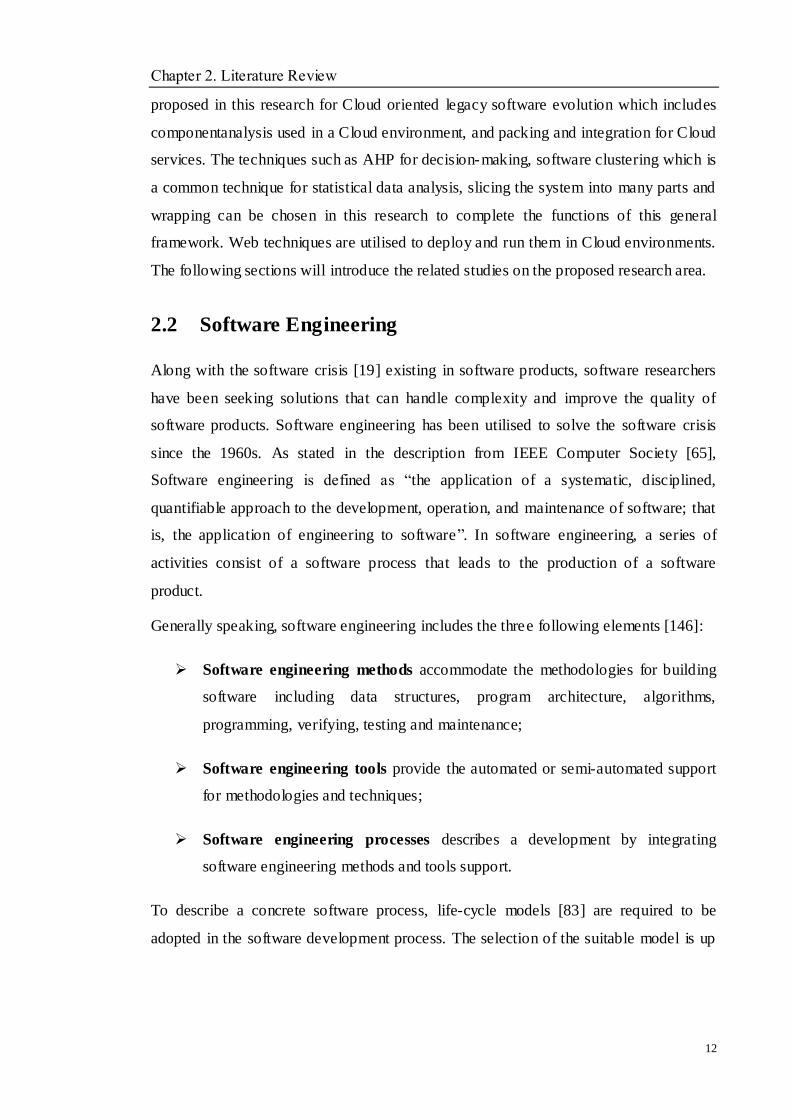
introduction in[146], the software evolution should include the following features: (1)
the ability to handle sequential and parallel systems by reverse engineering and forward
engineering, (2) the ability to deal with object-oriented systems. The evolutionary life of
software is shown in Figure 2-1 [146].
Figure 2-1Evolutionary life of Software [146]
Legacy system evolution means that the legacy system is evolved into a new operating
system, system architecture, hardware, or middleware platforms. During this process,
some research fields have been referred, such as, reverse engineering, migration schema
mapping, business reengineering, program transformation, application development,
human computer- interaction, testing and so on.

Chapter 2. Literature Review
17
For legacy system evolution, it is not simple work. It can be viewed as a constrained
problem solving activity [125]. However, a number of challenges [64] are still
considered:
Documentations : most legacy systems are facing problems on documentation such
as outdated requirements and descriptions, undocumented pre- and post- adjustment
for implementation, etc.
Skills and schedule : developers have little effective and systematic skills in
business processes to handle the implementations. It is not easy to identify what
parts can be cost-effectively reused. In addition, schedule overrun is also a problem
that has to be managed.
Cost and feasibility: the ratio of cost and benefit as well as the technical feasibility
for evolving the applications into new computing environments should be assessed
firstly. After making sure there are no problems on risk and technology, the project
can be prepared to start.
Management: management needs to be effective to solve when different
development groups are developing different types of applications, technologies, or
relevant areas. Tools and strategies for handling effective cooperation are essential
for the success of legacy system evolution process.
A generic migration process includes the following steps [107]:
Justification.
It is the preparing stage of any application development before conducting related work.
Legacy system understanding.
It is the basis for the success of the evolution process.
Target system development.
This is a key phase of some evolution projects, and the selected environment for the
target system should be helpful to implement the application requirements of domain
targets.
Testing.

Chapter 2. Literature Review
18
It is a process that ensures whether the process of the legacy system evolution is
successful.
Evolution.
It describes the implementation from the legacy system to the target system in the
selected computing environment. Understanding how the legacy system works and how
it is used is the basis for reuse in a Cloud computing environment. Thus, the starting
point should be to find what exactly exists in legacy components, namely, to understand
and analyse legacy components.
2.3.3 Software Reengineering
Software reengineering is a form of modernisation that advances the capabilities of a
legacy system by adopting novel techniques. The purpose of software reengineering is
to utilise existing software to absorb new methodologies to reuse the existing systems.
Software reengineering is essential in software evolution. As is known, system
replacement can be expensive, while reengineering will be much cheaper. In addition,
software reengineering can reduce certain risks of losing essential information in legacy
assets. Many researchers have given a definition of software reengineering. Chikofsky
and Cross [32]recognise it as ―the examination and alteration of a subject system to
reconstitute it in a new form and subsequent implementation of that form‖. In[3], it is
defined as ―the activity that can improve the understanding of software or software
through the reusability, maintainability or evolvability‖.
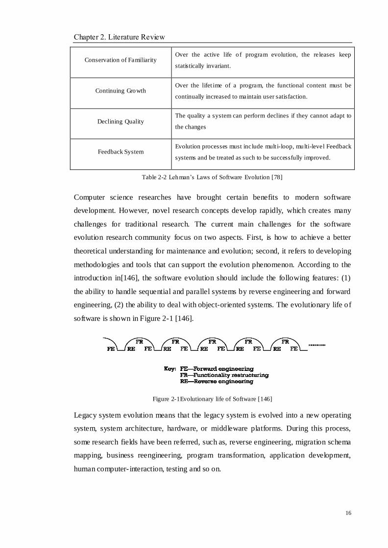
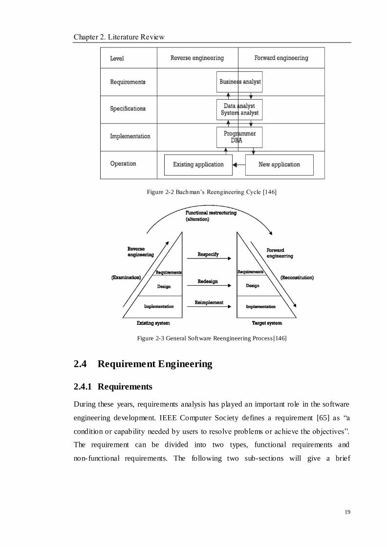
In order to understand the process of software reengineering, Bachman [6] described a
software reengineering cycle chart. Moreover, as shown in Figure 2-2 and 2-3, reverse
engineering and forward engineering are contained in software reengineering. The
process of reverse engineering on the existing system starts with operation, i.e., defining.
Then the definition can be dropped to a higher level for implementation, and then the
specification and requirements are conducted. In order to utilise forward engineering,
the final result from reverse engineering will be validated and enhanced. Once the new
application is built it will become the existing one again after it goes into production.
Hence, the software reengineering cycle has been generated.
Chapter 2. Literature Review
19
Figure 2-2 Bachman‘s Reengineering Cycle [146]
Figure 2-3 General Software Reengineering Process [146]
2.4 Requirement Engineering
2.4.1 Requirements
During these years, requirements analysis has played an important role in the software
engineering development. IEEE Computer Society defines a requirement [65] as ―a
condition or capability needed by users to resolve problems or achieve the objectives‖.
The requirement can be divided into two types, functional requirements and
non-functional requirements. The following two sub-sections will give a brief
Chapter 2. Literature Review
20
introduction for both.
2.4.1.1 Software Functions
A typical functional requirement will describe what the system can do. This information
is used to help the reader understand why the requirement is needed, and to track the
requirement through the development of the system [110]. Functional requirements are
able to capture the intended behaviour of the system. This behaviour could be expressed
as services, tasks or functions that the system is required to perform. In product
development, it is useful to distinguish the baseline functionality necessary for any
system to compete in that product domain, and features that differentiate the system
from competitors‘ products, and from variants in any company‘s own product line.
Features may be additional functionality, or differ from the basic functionality along
some quality attribute (such as performance or memory utilization). According to the
contents in [10, 71], the typical functional requirement examples can be described as:
interface requirements, business requirements, security requirements and so on.
2.4.1.2 Software Non-functional Requirements
Software quality properties, normally derived from non-functional requirements, are
becoming more important in the early steps of software design, influenced greatly by
the software systems architecture. Although the system‘s core abstractions are
functional requirements, software qualities play an important role in the definition of the
initial architecture. On the other hand, the quality attributes will assist with functional
requirements to implement the software design process.
Some well-known quality models are McCall [95], Boehm [15], FURPS [51], and
Dromey [37]. Each one of these quality models consists of a number of quality
characteristics (or factors, as called in some models). These quality characteristics could
be used to reflect the quality of the software product from the view of that characteristic
Based on those models, ISO released the international standard ISO 9126-1[68], in this
standard, quality is defined as a set of features and characteristics of a product or service
that bear on its ability to satisfy stated or implied needs. In 2011, Systems and software
engineering--Systems and software Quality Requirements and Evaluation (SQuaRE) --
System and software quality models have been published and the quality model has
Chapter 2. Literature Review
21
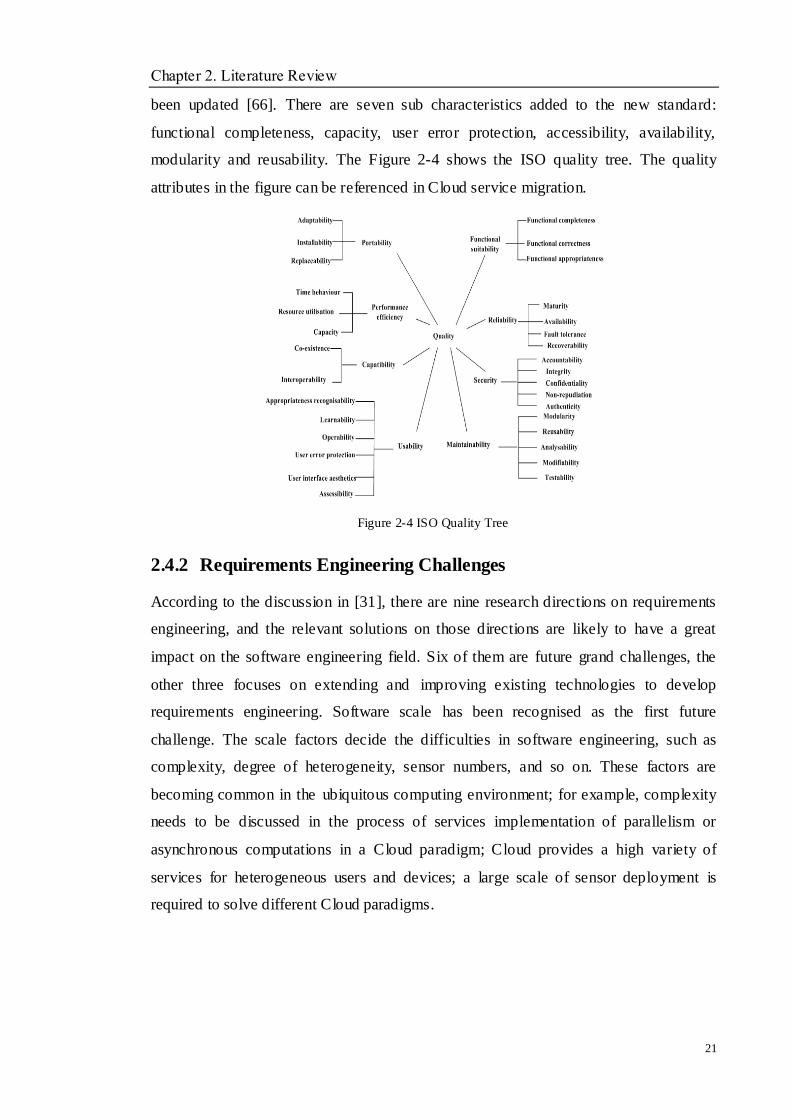
been updated [66]. There are seven sub characteristics added to the new standard:
functional completeness, capacity, user error protection, accessibility, availability,
modularity and reusability. The Figure 2-4 shows the ISO quality tree. The quality
attributes in the figure can be referenced in Cloud service migration.
Figure 2-4 ISO Quality Tree
2.4.2 Requirements Engineering Challenges
According to the discussion in [31], there are nine research directions on requirements
engineering, and the relevant solutions on those directions are likely to have a great
impact on the software engineering field. Six of them are future grand challenges, the
other three focuses on extending and improving existing technologies to develop
requirements engineering. Software scale has been recognised as the first future
challenge. The scale factors decide the difficulties in software engineering, such as
complexity, degree of heterogeneity, sensor numbers, and so on. These factors are
becoming common in the ubiquitous computing environment; for example, complexity
needs to be discussed in the process of services implementation of parallelism or
asynchronous computations in a Cloud paradigm; Cloud provides a high variety of
services for heterogeneous users and devices; a large scale of sensor deployment is
required to solve different Cloud paradigms.
Chapter 2. Literature Review
22
2.5 Software Architecture
In the 1990s, software architecture became an independent research area. Software
architecture is the representation of a software system at the highest possible level of
abstraction. It is the representation of the earliest design decisions that need to be made
in order to build a software system. Software architecture is mainly a collection of
components that make up the software system. There are several available definitions of
software architecture [9, 72], but this study will talk about one of the most popular ones.
One of the more commonly used definitions has been given by Kazman in [9], which
states ―the software architecture of a program or computing system is the structure or
structures of the system, which comprise software components, the externally visible
properties of those components, and the relationships among them.‖
2.5.1 Software Architecture Styles
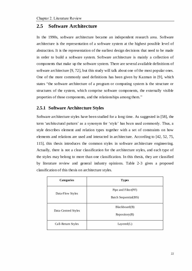
Software architecture styles have been studied for a long time. As suggested in [58], the
term ‗architectural pattern‘ as a synonym for ‗style‘ has been used commonly. Thus, a
style describes element and relation types together with a set of constraints on how
elements and relations are used and interacted in architecture. According to [42, 52, 75,
115], this thesis introduces the common styles in software architecture engineering.
Actually, there is not a clear classification for the architecture styles, and each type of
the styles may belong to more than one classification. In this thesis, they are classified
by literature review and general industry opinions. Table 2-3 gives a proposed
classification of this thesis on architecture styles.
Categories Types
Data-Flow Styles
Pipe and Filter(PF)
Batch Sequential(BS)
Data-Centred Styles
Blackboard(B)
Repository(R)
Call-Return Styles Layered(L)
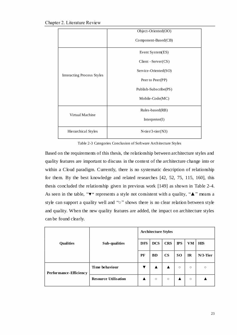
Chapter 2. Literature Review
23
Object-Oriented(OO)
Component-Based(CB)
Interacting Process Styles
Event System(ES)
Client –Server(CS)
Service-Oriented(SO)
Peer to Peer(PP)
Publish-Subscribe(PS)
Mobile-Code(MC)
Virtual Machine
Rules-based(RB)
Interpreter(I)
Hierarchical Styles N-tier/3-tier(N3)
Table 2-3 Categories Conclusion of Software Arch itecture Styles
Based on the requirements of this thesis, the relationship between architecture styles and
quality features are important to discuss in the context of the architecture change into or
within a Cloud paradigm. Currently, there is no systematic description of relationship
for them. By the best knowledge and related researches [42, 52, 75, 115, 160], this
thesis concluded the relationship given in previous work [149] as shown in Table 2-4.
As seen in the table, ―▼” represents a style not consistent with a quality, ―▲‖ means a
style can support a quality well and ―○‖ shows there is no clear relation between style
and quality. When the new quality features are added, the impact on architecture styles
can be found clearly.
Qualities Sub-qualities
Architecture Styles
DFS DCS CRS IPS VM HIS
PF BD CS SO IR N/3-Tier
Performance-Efficiency
Time behaviour ▼ ▲ ▲ ○ ○ ○
Resource Utilisation ▲ ○ ○ ▲ ○ ▲
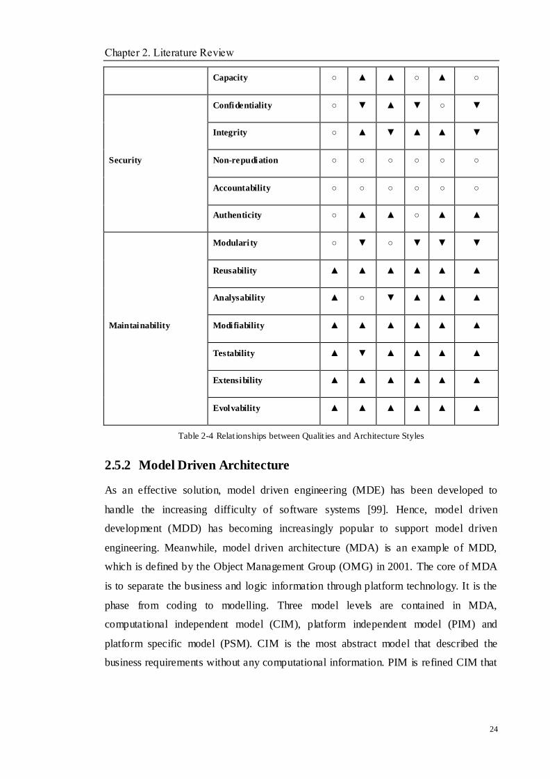
Chapter 2. Literature Review
24
Capacity ○ ▲ ▲ ○ ▲ ○
Security
Confidentiality ○ ▼ ▲ ▼ ○ ▼
Integrity ○ ▲ ▼ ▲ ▲ ▼
Non-repudiation ○ ○ ○ ○ ○ ○
Accountability ○ ○ ○ ○ ○ ○
Authenticity ○ ▲ ▲ ○ ▲ ▲
Maintainability
Modulari ty ○ ▼ ○ ▼ ▼ ▼
Reusability ▲ ▲ ▲ ▲ ▲ ▲
Analysability ▲ ○ ▼ ▲ ▲ ▲
Modifiability ▲ ▲ ▲ ▲ ▲ ▲
Testability ▲ ▼ ▲ ▲ ▲ ▲
Extensibility ▲ ▲ ▲ ▲ ▲ ▲
Evolvability ▲ ▲ ▲ ▲ ▲ ▲
Table 2-4 Relat ionships between Qualit ies and Architecture Styles
2.5.2 Model Driven Architecture
As an effective solution, model driven engineering (MDE) has been developed to
handle the increasing difficulty of software systems [99]. Hence, model driven
development (MDD) has becoming increasingly popular to support model driven
engineering. Meanwhile, model driven architecture (MDA) is an example of MDD,
which is defined by the Object Management Group (OMG) in 2001. The core of MDA
is to separate the business and logic information through platform technology. It is the
phase from coding to modelling. Three model levels are contained in MDA,
computational independent model (CIM), platform independent model (PIM) and
platform specific model (PSM). CIM is the most abstract model that described the
business requirements without any computational information. PIM is refined CIM that
Chapter 2. Literature Review
25
represents the business functions and application behaviour in an independent manner.
Finally, PSM introduces how a software system can be implemented with given
technologies in a specific platform. In the process of completing MDA, semi-automated
transformations, can be applied among the three models.
2.6 Computing Paradigm
Up-to-date software systems can change with the business, customer requirements, and
hardware and environment changes. However, there are still many software systems that
cannot satisfy the ever-changing computing environments and requirements, and
become legacy ones. Hence, related approaches are required in the existing computing
paradigms.
2.6.1 Grid Computing
Grid computing builds on the pooling of resources model by adding administrative and
operational functions that manage the discovery and dynamic allocation, monitoring and
reporting of grid status, and so on [43]. When hundreds or thousands of servers are
clustered and managed as a single massive computing resource, the processing power is
enormous. Grids have been created to support scientific, commercial purposes and
government communities who have significant computing and data storage
requirements. However, there is a flaw in grid computing in that it includes too much
detail of the implementation, and it may make the application develop more complexly,
with difficult interoperability and scaling. When looking for a solution at a higher and
more abstract level, cloud computing becomes more popular and plays a vital role as the
new computing platform paradigm.
2.6.2 Internetware
With the popularity of the Internet, a wide range of Internet applications has raised new
demands and challenges such as openness, portability, quick online reconfiguration and
adaptation. User requirements are constantly changing when software is produced. In
other words, the open, dynamic and distributed natures of the Internet have forced
up-to-date software models and evolution approaches to be sought which shall be more
Chapter 2. Literature Review
26
and more autonomous, situational and coordinative. The term, Internetware [92, 96, 145,
153] is constructed by a set of autonomous software entities distributed over the Internet,
together with a number of connectors enabling the collaboration among these entities in
various statuses. Entities are able to be aware of the dynamic changes of the running
environments, and continuously adapt to these changes with software development
techniques. Internetware software has these features, such as being autonomous,
evolvable, situational and trustworthy. The previous work also discussed the
architecture style change on an Interternetware paradigm [156, 158], and the
architecture style discussion is also appied in this thesis.
2.6.3 Cloud Computing
Cloud computing [4] has emerged as an important trend in information technology in
recent years. Cloud computing provides a paradigm for provisioning and releasing
computing resources, i.e., software, hardware, infrastructure, platforms, etc., with
minimal management efforts, meanwhile enabling a convenient service, on demand
network access to a shared pool of those configurable resources. Cloud computing is a
natural evolution of the widespread adoption of virtualization, Service-oriented
architecture and utility computing. The major cloud service providers include Amazon,
Salesforce and Google. Some of the larger IT firms that are actively involved in cloud
computing are Fujitsu, Microsoft, IBMVMware, NetApp and Dell. In order to
understand the Cloud , a few previous works have investigated the Cloud [157, 159].
As an emerging paradigm, there are many advantages that can be acquired from it.
Lower computer costs
Improved performance
Reduced software costs
Instant software updates
Unlimited storage capacity
Increased data reliability
Latest version availability
Chapter 2. Literature Review
27
Device independence
Improved document format compatibility
Universal document access
Although there are pros of Cloud computing, ten obstacles for Cloud have existed [4].
Considering the obstacles, the cloud applications should contain the relevant features of
a software quality model to overcome these obstacles.
1. Availability of a service
2. Data lock- in
3. Data Confidentiality and auditability
4. Data transfer bottlenecks
5. Performance unpredictability
6. Stable storage
7. Bugs in large-scale distributed systems
8. Scaling quickly
9. Reputation fate sharing
10. Software licensing
With the development of Cloud computing, there are many types of public cloud
computing services [100]:
Infrastructure as a service (IaaS).
Storage as a service (STaaS).
Software as a service (SaaS).
Platform as a service (PaaS).
Desktop as a service (DaaS).
Data as a service (DaaS).
API as a service (APIaaS).

Chapter 2. Literature Review
28
Test environment as a service (TEaaS).
Security as a service (SECaaS).
Business process as a service (BPaaS).
2.7 Legacy System Decomposition
Software systems can be changed with the business, customer requirements and the
external environment needs. However, many software systems will become legacy ones
because they cannot satisfy the dynamic requirements of users and environments. In
order to reuse the useful parts, certain identification for a legacy system needs to be
adopted.
The process of decomposing the legacy system is to analyse the legacy systems and
capture independent legacy code segments that can be extended into Cloud services.
Legacy systems decomposition is an initial step for legacy system migration. The legacy
system migration is dependent on its decomposability. If the decomposability of the
system is not enough, the migration process should become more difficult [18].
Normally, there are three types of components that are composed in a software system,
which can be concluded as interface components, application logic components, and
database components. Depending on how separated and well identified these
components are, the architecture of a legacy system can be divided into decomposable,
semi-decomposable, or non-decomposable. For non-decomposable systems, the three
components will be not easy to separate; for semi-decomposable systems, interface
components are isolated from the other domain logic and database components; for
decomposable systems, all three components are able to be separated.
There are three types of components which may be included in each program of a
legacy system. Decomposing a program is used to identify and re-organise different
level components. Many approaches and techniques have been investigated in this
research. Currently, there are mainly three types of legacy program decomposition
approaches [22, 118]:
The approach for procedure
Chapter 2. Literature Review
29
For this approach, a program can be seen as a directed graph and the decisions are
regarded as nodes and the branches are thought of as edges. Complex graphs will be
split into sub-graphs by searching the points of minimum interconnections. Moreover,
program restructuring and reusable functions are also aided by program slicing
techniques.
The approach for function
For this approach, a program is analysed based on a functional decomposition; the
program will be divided into a hierarchy of super control nodes and sub-basic nodes and
each business rule will be adopted to deal with one or more control nodes [48, 49, 50].
The approach for data type.
For this approach, a program can be analysed and decomposed into a collection of
cooperating processing objects; modules can be generated together as the collection of
operations on a known data type or entity.
In addition, other approaches for the decomposition of reusable components from
legacy systems [17, 21, 88] are also contributed.
Service oriented architecture migration solution has also always been involved to reuse
decomposed legacy components through identifying them as services, operations,
business processes, and business rules. In brief, business modelling can guide legacy
system understanding and decomposition in SOA evolution.
In other words, reverse engineering techniques can be applied on the implementation
process of legacy system analysis. There are a series of main works, which include
identifying the legacy components and their relationships with each other and creating
representations of the components in a higher and computational abstraction level. For
identifying the legacy components and their relationships, program slicing and software
clustering have been utilised by the researchers.
2.7.1 Legacy System
According to [8, 57, 77, 86], legacy systems can be explained as follow:
They are difficult or invaluable to improve, extend or integrate with the new

Chapter 2. Literature Review
30
requirements of business and users.
They will spend more costs to maintain in the relevant environments.
Most of them cannot fulfil the end users‘ needs because of poor performance,
outdated functions and integration requirements.
With the fast development of Web technology and computing environments, the amount
of legacy systems has been becoming larger, which will reduce the software
organisation‘s competitive abilities with other outstanding business.
However, legacy systems cannot be discarded simply. There are several reasons for
Legacy systems to be worth reusing in part or in whole [86]:
A large number of critical data and business logic included in most legacy systems
are still required to support current business processes.
Reusing a legacy system can be a cost-effective way to achieve new objectives for
enterprise without more cost and time on designing new applications.
Most legacy systems have been served for the users and they still have a certain
occupation in the market.
In these years‘ research, many researchers have depicted the values of legacy systems.
In [114], legacy system can be reused with other business requirements to get better
performance. Some business reasons can be integrated into legacy system with new
solutions.
Wrapping the system as a new component in larger scale systems and modifying the
system to support the new requirements have been introduced in [91]. These solutions
have gained a series of achievements. There are also the researches on which the
approach can be used to decide whether the legacy systems have the b usiness value to
reuse [13, 90].
By extension, transformation, integration and migration, most legacy assets can be
reused. Currently, many software organisations want to migrate legacy systems to new
computing environments that are helpful for the maintenance and deployment of new
information requirements.The main purpose of legacy systems migration is to reuse the
useful functions in new computing environments. Thus, it is important and valuable to
Chapter 2. Literature Review
31
analyse the legacy system.
2.7.2 Program Slicing
Mostly legacy systems are complex and huge. Many benefits such as more flexibility
and reliability can be obtained by slicing a system into small parts. Program slicing is a
software maintenance way to identify the value of a given variable in a program code. It
has been used in reverse engineering, testing and debugging. It is available in the
research prototypes and commercial applications [5] .
The idea of program slicing was proposed by Weiser [126] as a way to compute a slice
by calculating continuous sets of indirectly corresponding statements through control
flow and data flow dependences [14]. A static slice is referred to as statically available
information for computing slices. Dynamic slicing [33] was introduced for a given input
by maintaining an execution statement of the syntax tree and marking the nodes during
the relevant runtime statement [97]. For OO system, utilising dynamic data dependence
(DD) analysis can extract the values of all the variables on the execution and the static
control dependence (CD) analysis could save the time to record execution.
There are several main approaches for program slicing. The original slicing method
from Weiser [44] is based on traditional data flow analysis [142]. Then, an approach is
based on program dependence graphs (PDG) [41]. Extensive evaluations of different
slicing algorithms are described in [23, 59]. With the development of object oriented
languages, the traditional slicing techniques for procedural programs are not fully
suitable for object oriented programs because they have new concepts such as class,
dynamic binding, inheritance and polymorphism [16]. Horwits develops the system
dependence graph (SDG) and a two-phase algorithm to compute interprocedural slice
[60]. Some researchers have improved the SDG to handle the slicing process. For
example, The works in [76, 155] respectively proposed static and dynamic slicing
methods for object oriented programs. The static slicing may include more statements
because of inheritance and polymorphism. Dynamic slicing requires more time and
space to record the execution trace. OHATA et.al.proposed to combine [154] the static
and dynamic information between the data flow dependence analysis and control flow
dependence analysis. The advantage of this method can resolve the dynamic data
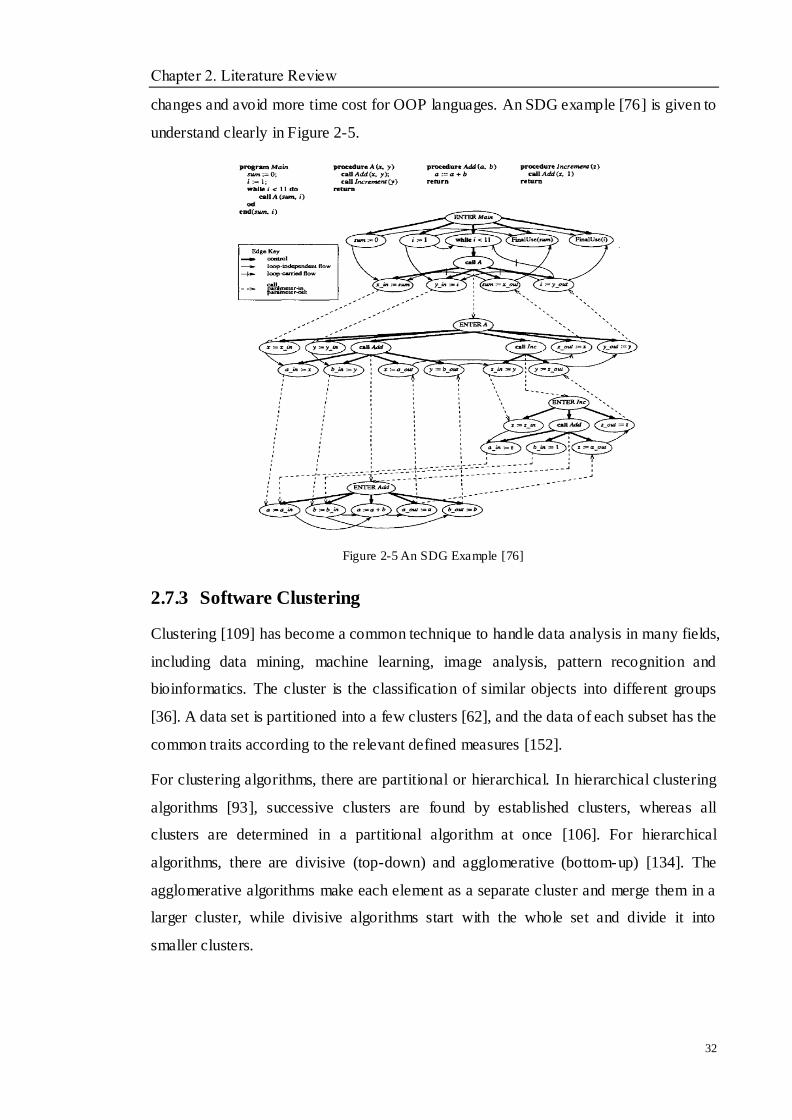
Chapter 2. Literature Review
32
changes and avoid more time cost for OOP languages. An SDG example [76] is given to
understand clearly in Figure 2-5.
Figure 2-5 An SDG Example [76]
2.7.3 Software Clustering
Clustering [109] has become a common technique to handle data analysis in many fields,
including data mining, machine learning, image analysis, pattern recognition and
bioinformatics. The cluster is the classification of similar objects into different groups
[36]. A data set is partitioned into a few clusters [62], and the data of each subset has the
common traits according to the relevant defined measures [152].
For clustering algorithms, there are partitional or hierarchical. In hierarchical clustering
algorithms [93], successive clusters are found by established clusters, whereas all
clusters are determined in a partitional algorithm at once [106]. For hierarchical
algorithms, there are divisive (top-down) and agglomerative (bottom-up) [134]. The
agglomerative algorithms make each element as a separate cluster and merge them in a
larger cluster, while divisive algorithms start with the whole set and divide it into
smaller clusters.
Chapter 2. Literature Review
33
Software clustering techniques have been applied to capture reusable legacy code
segments [73], which show the characters of independent, loose coupling and
self-contained [143]. Meanwhile, it is also adopted in the program understanding area,
including component recovery [128] and re-modularisation [113]. All these
contributions have proved that software clustering is useful to identify objects based on
the legacy system.
2.7.4 Wrapping Technique
To modernise a legacy system at user interface, data and logic level [124], wrapping
technology is used to integrate the legacy system to the service wrapper code. In [116],
wrapping can be divided into five levels, which are job level, transaction level, program
level, module level and procedure level. Wrappers encapsulate legacy executive
processes at process level and transaction level. Legacy applications will be invoked by
wrappers through creating a requested new process. At the application level, wrappers
only encapsulate a process. At the module level and procedure level, the encapsulation
focuses on interfaces and re-modularised legacy code. The goal of the wrapping
technique is to provide the service extracted from the legacy system with a WSDL [131]
interface. The used technique is to transform each item into a method and to transform
each parameter into an XML data. Both the methods and parameters are built into XML
schema [132]. Eclipse XSD editor has been developed to create XML schema. A
WSDL interface can be generated by an eclipse with the input and output parameters,
the function name, the messages, and the port type with its input and output messages.
2.8 Software Evolution Approaches
2.8.1 Service-Oriented Software Evolution
Software evolution can be thought of as continuous software reengineering tasks. It
aims to implement and reconcile the possible external changes for the existing software
systems to fulfil the dynamic requirements. On the other hand, services can be
performed well by excellent software systems. Services are the core of service oriented
software evolution, and the term service has been widely used. Different researchers or
organisations have different opinions on the definition of service, which always
Chapter 2. Literature Review
34
generates a lot of arguments. Based on a general definition from IBM [63], the service
has been defined as: ―A service is generally implemented as a course-grained,
discoverable software entity that exists as a single instance and interacts with
applications and other services through a loosely coupled (often asynchronous),
message-based communication model.‖
In order to acquire better services, service users hope to get the good behaviours from
their current software system. Therefore, service oriented evolution is also proposed in
these years. Generally speaking, service oriented evolution is used to stress the nature of
computer based applications and the mechanism for evolving computer programs [25].
Along with the popularity of the Internet, a great amount of attention has been focused
upon service-oriented computing (SOC). SOC is the computing paradigm that utilises
services as fundamental resources for developing applications. Because services provide
a uniform and standard information paradigm for a wide range of computing devices,
they will be vital in the next phase of distributed computing development. The
developers can compose existing web service components to create new applications
and evolve legacy systems to be suitable for complex service requirements. In [69, 117],
a technique for wrapping existing web applications with WSDL descriptions is built so
that providers with a presence on the ―browser-accessible web‖ can easily transfer their
functionalities to other applications. The SOSR [34] methodology is focused on service
orientation and its specific tasks, using the UML modelling technique to support
software developers to evolve a legacy software system. In [28], the researchers also
present an approach to supporting Service-Oriented evolution.
In [48], the work represents a migration approach that combines a generally top-down
driven SOA design to aid the SOE process with bottom-up elements such as application
portfolio assessment and program understanding techniques.
Zhang et al. [154] contributed an approach on migrating legacy system to support SOE,
which included legacy system evaluation, architecture recovery, service identification,
service packaging, service publication and choreography.
Canfora et al. [24] described a wrapping approach for migrating legacy system
Chapter 2. Literature Review
35
interactive functionalities to a service oriented computing paradigm. The wrapper
behaviour is defined by black-box reverse engineering of the human–computer interface.
It describes a black-box modernisation approach for wrapping relevant functionalities of
legacy systems as services.
According to [129], the work depicted a strategic decision model to aid SOE projects
that merge strategic and technical factors via cost benefit analysis for deciding
integration versus migration. This reengineering decision support model contains four
parts, which are strategic analysis, architecture analysis, solution development and
implementation. However, it just concentrates on the technical migration itself and the
lack of detailed implementation details.
Lucia et al. [91] introduced an incremental migration strategy in order to wrap the
legacy systems at the user interface level. In order to support SOE, an assessment of the
legacy systems was performed in terms of business value and software quality. An
Eclipse plug- in called MELIS (migration environment for legacy information system),
has been designed to support all the migration process.
2.8.2 Requirement-Oriented Software Evolution
Requirement oriented evolution is just starting to develop in the last few years and it has
not drawn much attention from researchers. Although the authors [31] suggest that
close attention should be paid whilst there is a rapid development of Cloud computing.
Requirements can be divided into functional ones and non-functional ones. Chapter 2
has introduced and described them for requirement engineering. The following content
will only discuss the challenge of ROE and its relevant positive results.
Harris and Dobson [56] first discussed the change and challenge of ROE. They
described the structure of requirements and also give the changes of the requirement
types, such as Mutable Requirement (environmental turbulence origin), Migration
Requirement (constraints of planned organisational development origin) and Adaptive
Requirement (situated action and task variation origin) and so on.
In order to improve requirement evolution management, Fabbrini et al. [40] depicted an
approach to making more efficient and enhancing the identification of semantic
Chapter 2. Literature Review
36
inconsistencies during each stage of requirements evolution. They utilise ―FAdopting‖
Formal Concept Analysis (FCA) to validate the requirement evolution.
A requirement engineering framework and methodology were proposed to support
requirement evolution by Lormans [89]. In this research, the traceability of
requirements is improved effectively.
In the work of Ernst et al. [39], they predict that there will be code, documentation,
requirements and other types of models, which will compose the future software
systems. These are important reasons why requirements evolution is about to become a
crucial point in requirement oriented evolution and Cloud computing research.
With the discussion of the assumptions of requirement oriented evolution, the
researchers are trying their best to change it from assumption to reality. According to
Ali et al. [1], they depict an approach to monitoring the assumptions in a requirements
evolution model and to continuing to evolve the model to implement those assumptions.
In their view, requirement oriented evolution can be accomplished in practice.
2.8.3 Grid-Oriented Software Evolution
Middleware has been developed as reusable software, which can be deployed among the
applications, hardware and operating systems. In Grid environment, middleware
technology has been seen as an attractive way to resolve complex computing tasks.
Grid middleware [85] has performed a series of new capabilities for current distributed
services, which can be improved with these supports. In order to implement Grid
oriented evolution (GOE), reusing existing software components and information
services can be chosen with the new reengineering approaches. For this reason, many
researchers have raised the awareness of Grid programming to reduce the academic
complexities in the process of GOE.
With the support of process coordination [7] and process migration, a series of
efficiency Grid systems have been acquired and improved to run in the business
environment. According to the work [29], the old software systems have been evolved
to Grid systems, which become more efficient and effective. Meanwhile, it helps to
relocate processes in the Grid environment with data that they could access easily.

Chapter 2. Literature Review
37
In [46], the researcher described an ecological network-based Grid middleware, which
is useful to implement GOE successfully. This technique can provide a new computing
and problem-solving way by combining traditional computing mechanisms with agent
technologies to support timely requirements of new Grid systems, and which can fulfil
the features of Grid computing, i.e., adaptability, scalability, self-organisation, and
survivability. There are also many successful GOE cases that have helped the enterprise
to get certain benefits and provided relevant experience for COE implementation.
NAREGI [127] aims to research and design a high-performance, feasible Grid
middleware for a scientific computational infrastructure. This middleware will help
establish the Grid computing centres worldwide in the Grid research area to implement
the relevant Grid development besides Grid oriented software evolution.
In order to provide a programming interface for migrating software systems into Grid
infrastructure, the Grid Application toolkit [2] has been developed to handle the
complexity and the variety of Grid paradigms.
The work in [70] introduces how the deployment of legacy code can be transferred to
Grid services without modifying the original legacy code. But this approach only
focuses on a special environment, which is based on the open grid services architecture.
2.8.4 Cloud-Oriented Software Evolution
Although Service-Oriented software evolution has developed well, the new
requirements are waiting for the new paradigm that can be suitable for the dynamic
environment. Both academia and enterprise have studied and proposed a few
architecture frameworks to connect Cloud computing with Service-Oriented
methodologies.
With years of effort, Cloud researchers have successfully developed C loud computing,
including security solutions, resource management methods, information collection, and
data management services. Due to the ultimate goal of C loud computing being to design
an infrastructure which supports dynamic resource sharing, there is a need for evolving
legacy systems into the Cloud environment. They believe that the legacy software
systems can be evolved into Service-Oriented Cloud architecture. Hence, the

Chapter 2. Literature Review
38
researchers have made some progress about software evolution based on
Service-Oriented Cloud architecture. The following work will introduce related work in
Cloud computing environments.
Tan et al. [123] proposed an approach to SaaS integration for software cloud. This work
describes a Proxy-based firewall/NAT traversal solution for SaaS integration, which
allows SaaS applications to integrate with existing applications without firewall
reconfiguration, while ensuring the application security.
Based on the work [61], this research depicts the potential benefits in a case study of
migrating an enterprise IT system to IaaS Cloud. The findings of the case study have
proved that Cloud computing can be crucially cheaper to purchase and maintain the
system infrastructure. Furthermore, there are also important issues that need to be
checked before migration into Cloud paradigms.
Guo et al. [53] introduced a framework of enterprise Cloud application to bridge the
power of service oriented architecture that can make the application become more
flexible and reusable. There are five framework principles and three modules to make
up the framework. Meanwhile, some potential value-added services are also presented
as a guide to how to move the applications from enterprises to Cloud.
In [108], the Cloud computing architecture, Reservoir, is proposed to create an
association with multiple Cloud providers. In the Reservoir architecture, the
computational resources within one site are partitioned by the virtualisation and utilised
into a virtual environment.
A software platform for .NET based Cloud computing named Aneka in [130] is
introduced. It is an extensible and scalable Service-Oriented environment, which
enables developers to operate easily .Net applications supports multiple programming
models and APIs, and it can be considered as a pure PaaS C loud solution.
Chauhan [26] provided a method to migrate a special software system to the SaaS
system. In [150, 151], the researchers have proposed a C loud model and discussed the
relationship between Service-Oriented Architecture and a Cloud environment. However,
these researches do not allow the service to run on different environments; Moreover,
legacy resources are collected as services that might not be necessary for the entire
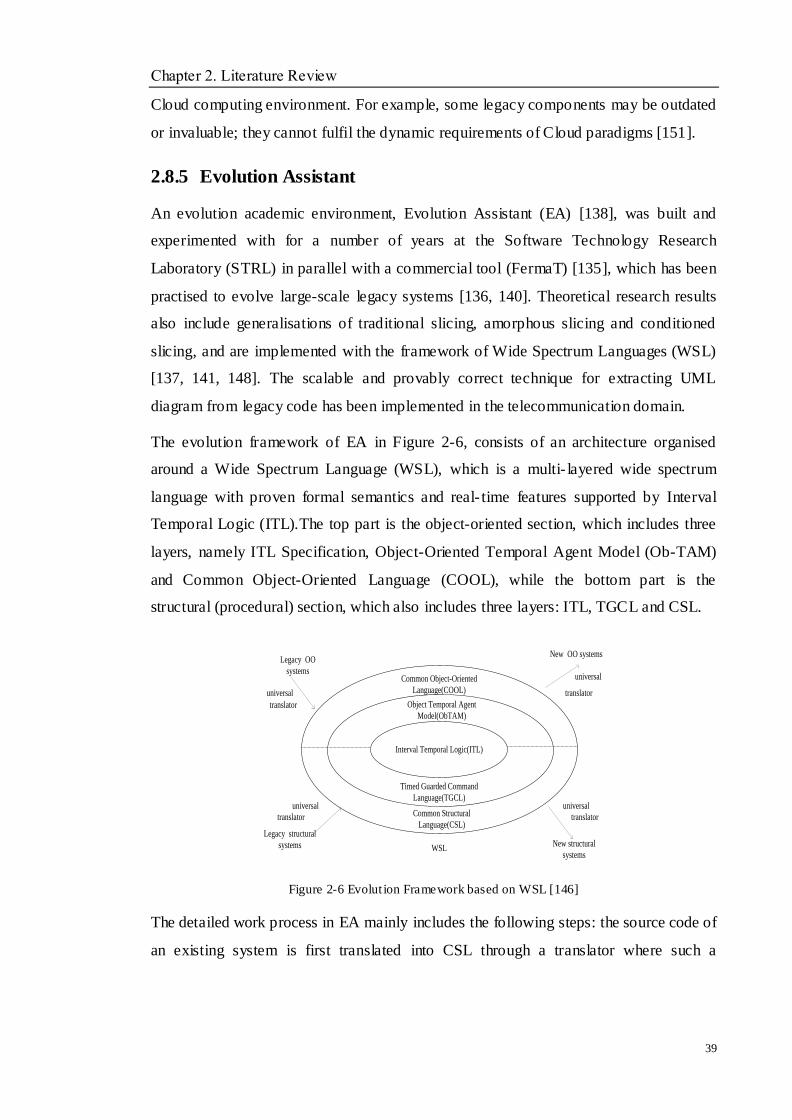
Chapter 2. Literature Review
39
Cloud computing environment. For example, some legacy components may be outdated
or invaluable; they cannot fulfil the dynamic requirements of Cloud paradigms [151].
2.8.5 Evolution Assistant
An evolution academic environment, Evolution Assistant (EA) [138], was built and
experimented with for a number of years at the Software Technology Research
Laboratory (STRL) in parallel with a commercial tool (FermaT) [135], which has been
practised to evolve large-scale legacy systems [136, 140]. Theoretical research results
also include generalisations of traditional slicing, amorphous slicing and conditioned
slicing, and are implemented with the framework of Wide Spectrum Languages (WSL)
[137, 141, 148]. The scalable and provably correct technique for extracting UML
diagram from legacy code has been implemented in the telecommunication domain.
The evolution framework of EA in Figure 2-6, consists of an architecture organised
around a Wide Spectrum Language (WSL), which is a multi- layered wide spectrum
language with proven formal semantics and real- time features supported by Interval
Temporal Logic (ITL).The top part is the object-oriented section, which includes three
layers, namely ITL Specification, Object-Oriented Temporal Agent Model (Ob-TAM)
and Common Object-Oriented Language (COOL), while the bottom part is the
structural (procedural) section, which also includes three layers: ITL, TGCL and CSL.
Figure 2-6 Evolut ion Framework based on WSL [146]
The detailed work process in EA mainly includes the following steps: the source code of
an existing system is first translated into CSL through a translator where such a
Interval Temporal Logic(ITL)
Timed Guarded Command
Language(TGCL)
Common Structural
Language(CSL)
Common Object-Oriented
Language(COOL)
Legacy structural
systems
translator
universal
New structural
systems
translator
universal
Legacy OO
systems
universal
translator
New OO systems
universal
translator
WSL
Object Temporal Agent
Model(ObTAM)

Chapter 2. Literature Review
40
translation ensures standardisation, followed by transformation to TGCL through
successive application of correctness-preserving transformation rules.
There are three possible paths for the evolution:
TGCL code can be improved/extended by adding the required extra functionalities.
If an Object Oriented paradigm is sought, object extraction is performed to obtain an
equivalent ObTAM code.
If a high level of abstract specification is needed, then following the construction of
TGCL code or/and ObTAM code, the semantics calculation is performed to produce an
ITL specification.
The screenshot of EA toolkit is shown in Figure 2-7. The functions of different parts in
the toolkit have been marked in the figure.
Figure 2-7 EA Screenshot
The tool is operating in a semi-automatic mode, i.e., the system will promote possible
operations, such as ―Transformations‖ and ―Abstractions‖ but a user will decide which
operations to apply. These rules are utilised in the transformation process of Cloud
service migration. Sample operations, selected from over 1000 in EA, include the
following categories:
Collapse_Action_System: to transform an action system into a sequence of statements,
possibly inside a DO loop.
Constant Propagation: to find assignments of constants to variables in the selected item
and propagate the values through the selected item.
Chapter 2. Literature Review
41
Delete_All_Redundant: to search for redundant statements and delete all the ones it
finds. A statement is `Redundant' if it calls nothing external and the variables it modifies
will all be assigned again before their values are accessed.
Reduce Loop: to make the body of a DO...OD reducible (by introducing new procedures
as #necessary) and to either remove the loop (if it is a dummy loop) or convert the loop
to a WHILE loop (if the loop is a proper sequence).
2.9 Summary
In this chapter the research background and related work are introduced:
A brief introduction of software engineering is reviewed and three components of
software engineering are described, which are methods, tools and processes. In the
software engineering process, four components are contained, which are software
specification, software design and implementation, software validation and
verification, and software evolution. Meanwhile, traditional software middleware
was also introduced.
A brief discussion on software maintenance, software evolution, software
reengineering and their definitions are described. Four categories of software
maintenance are introduced. The Lehman‘s law for software evolution and the
evolution cycle of software are depicted. A relation between software evolution and
software reengineering is given, and a general reengineering process of software
systems is represented.
Requirement engineering is introduced, and the categories of requirements are
given, software functional requirements and non-functional requirements. The
compositions of each category of requirements are also described. Finally, a series
of developing challenges on requirement engineering are given to be resolved in the
current research.
Software architecture and its styles are introduced. For software architecture styles,
its categories and the relationships between software architecture styles and
software qualities are discussed. A brief description of MDA is also given.

Chapter 2. Literature Review
42
A brief overview of ubiquitous computing and its paradigms are introduced. For
example, Grid computing, Internetware and Cloud computing. The development
and the advantages of them are described. A brief discussion of benefits, obstacles
and categories for Cloud computing marks the end of this chapter.
Legacy Components can be reused through extension, transformation, integration
and evolution. Legacy system evolution means that the legacy system can be
adapted to new computing environments. Legacy system understanding and
decomposition are very essential to the success of the evolution.
A great amount of attention has been focused upon service-oriented computing
(SOC). SOC is a computing paradigm that utilises services as fundamental
resources for developing applications. Therefore, SOE is also starting to develop in
order to satisfy the SOC requirement. Services can provide a uniform and standard
information paradigm for wide range of computing devices; they will prove vital in
the context of distributed computing development. In fact, Cloud can also be seen
as a service, the COE will be the extension of SOE.
Recently, the researchers have paid attention to software engineering from
requirements to code. This trend brings a great challenge for software reengineering.
Reverse engineering techniques have been applied on source code to analyse the
requirement content. Research on this aspect has been presented. Meanwhile,
forward engineering techniques can be adopted to deal with the implementation of
new requirements. However, it is still difficult to integrate the requirements and
current computing paradigms. Few works about evolving software into and within
Cloud environment with the support of requirements have not been mentioned.
Grid techniques with software evolution technologies have been studied for many
years by researchers. Most current works of Grid oriented evolution concentrate on
parts of the reengineering process and the proposition of a framework for evolving
legacy systems into a Grid environment. Grid middleware is also designed to
support the GOE development. Reusable resources from legacy systems have been
integrated in the Grid applications. Generally speaking, current approaches about
Grid oriented software evolution have been advanced and implemented, and these
techniques can also be referenced for the Cloud oriented software evolution.

Chapter 2. Literature Review
43
Cloud computing is an emerging paradigm for the intent of distributed resources
sharing and coordinated problem solution. Affected by the C loud trend and service
requirement need, many existing software systems have become legacy systems. In
order to fulfil the needs of resource reuse and cost reduction, these legacy software
systems will need Cloud oriented evolution, which can facilitate the legacy systems
reusable in Cloud oriented architecture and allow the integration of legacy
resources with Cloud features. However, most of the recent research of Cloud
oriented software evolution is still on web services, and few works give a general
framework of evolving software into and within a Cloud environment. Different
from the related studies, this thesis will introduce a novel approach to accomplish
this task, which handles software functions, software qualities and software models
together via a three-dimensional direction. What this proposed approach does will
provide a systematic and effective guidance to implement COE process.
Software evolution has been studied at Software Technology Research Laboratory
at De Montfort University since the early 1990‘s, with the aims of reducing the time
and cost of software maintenance so that organisations can expand the benefits
from legacy assets. During the twenty years‘ research of software evolution, this
laboratory has built an evolution assistant (EA) to evolve large-scale systems in the
distributed computing environments. For the evolution framework of EA, most
researches have been improving it to support emerging computing paradigms all the
time. The proposed approach in this thesis will also utilise EA to satisfy the COE
implementation.
Chapter 3. Proposed Framework
44
Chapter 3 Proposed Framework
Objectives
__________________________________________________________________
To introduce the whole proposed framework.
To describe the process of legacy system analysis and extraction.
To present the process of Cloud service migration.
To illustrate the process of Cloud service integration.
_________________________________________________________________
3.1 Overview
Current, software evolution has been regarded as continuous software reengineering,
and software reengineering is the core technique for successful evolut ion of software
systems. In general, software evolution can be composed of a series of phases, which
can be seen as a combination of reverse engineering, functional restructuring and
forward engineering.
In the process of reverse engineering, program comprehension techniques or formal
assignment could be adopted, i.e., analytic hierarchy process (AHP) [102]; during the
process of functional restructuring, abstraction and refactoring are utilised to implement
program and model transformation, and transformation rules and specific language
extension will be created and selected to support the implementation jobs; those
traditional techniques can be used or improved in the process of forward engineering.
Obviously, the COE project cannot leave the above phases. Meanwhile, the software
evolution for Cloud computing should be concluded from two phases, the process of
―INTO‖ Cloud and ―WITHIN‖ Cloud. The key evolution factors for each phase are
needed to choose suitably. A Cloud computing environment can be seen as a
three-dimensional paradigm based on the change of society computing tasks, hence, by
the same principle, the software evolution approach should also be designed from a
Chapter 3. Proposed Framework
45
three-dimensional one. According to the above analysis, systematic COE details are
required to ensure the implementation by the researchers and developers. Up to date,
little work in COE is completed and more problems are still waiting to be resolved.
During the research of COE project, the evolution is mainly affected by the problems
between what the legacy software will do and how the legacy software will do it. The
problems are shown as follows:
o Most legacy software systems are represented with inappropriate languages.
o Few research works consider the non-functional requirements, software functions
and software model together in the COE process.
o Few discussions are considered on the dimensions of society computing tasks and
computing environments.
Hence, a well-established technique and a novel evolution framework have become
necessary for COE project and it is important to developing relevant approaches within
the framework to support the successful implementation of software evolution process.
The success of a COE project depends on not only how well it fulfils the non-functional
requirements and software functions, but also how well it runs in the relevant computing
environments. In this research, a Cloud computing environment has been chosen as the
running environment. Deploying a legacy system into Cloud and evolving within Cloud
will be aided by a series of software evolution works. This research focuses on a
three-dimensional paradigm, which contains two requirement changes and a software
model, i.e., non-functional requirements (software qualities), software functions and
MDA. During the three-dimensional paradigm, function dimension describes general
business functions; software quality represents mainly the features of Cloud computing
such as reliability, elasticity, adaptability and availability, etc; and the software model is
at three levels as in MDA (CIM, PIM and PSM).
3.2 The Proposed Framework
During the software evolution process, the understanding of existing software (i.e., what
the system does) is required to decide what to modify in the software based on the new

Chapter 3. Proposed Framework
46
requirements, software model and computing environments, and how to implement
those modifications. To link the relationship among these three tasks, novel approaches
are needed to improve the traditional evolution approach. For example, many earlier
systems may only include a series of relevant requirements and model or may not have
them at all. To coordinate the three-dimensional evolution, the specifications of
requirements and model are essential, which can be prepared to support the COE
process into and within Cloud environment.
As investigated, computing only works when the methodologies may be modelled
correctly. It is known that computing has been advanced to such an extent that it can
model very complex society, which is achieved by building corresponding models. In
Table 3-1, society computing tasks from scientific computing, to personal computing
and then to ubiquitous computing, this can be seen as from being one dimensional, two
dimensional and then to three dimensional, are illustrated. Similarly, computing
environment is also from one dimensional to three dimensional. It is proposed that
Cloud computing can be seen as the three dimensional software paradigm after
structured and OO paradigms. According to the same principle, the software evolution
paradigm in a Cloud environment should also be three-dimensional.
Society (problem/application
domain)
Computing
Environment
Software
Paradigm
(e.g.)
Software
Evolution
(e.g.)
One-Dimensional Scientific Computing Single machine Structured Structured
Two-Dimensional Personal Computing Network OO OO
Three-Dimensional Ubiquitous Computing Cloud Cloud
platform Needed
Table 3-1Differences among Three Dimensional Models
In order to solve this program, it is now proposed that a three dimensional paradigm
consists of function, quality and model. Function dimension represents usual business
functions such as adaptation; quality represents mainly the features of Cloud such as
trust, security, etc; and model is at the three levels as in MDA (CIM, PIM and PSM),
which requires coordination with the other two dimensions. Figure 3-1 shows the
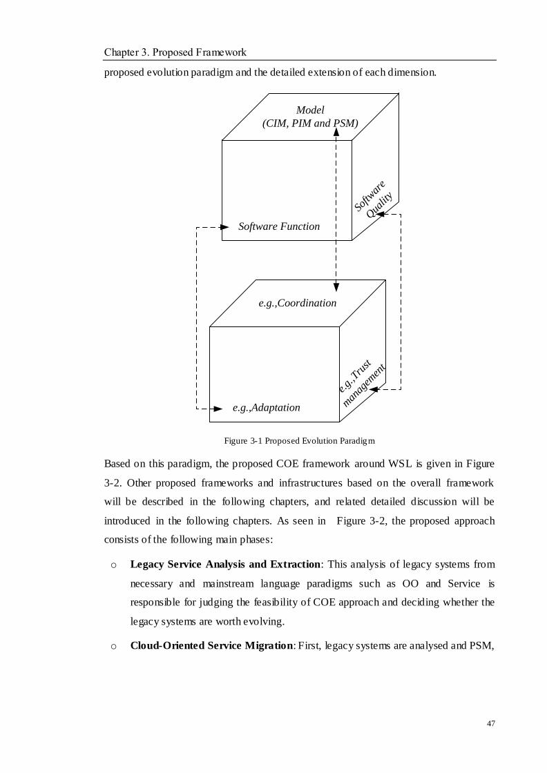
Chapter 3. Proposed Framework
47
proposed evolution paradigm and the detailed extension of each dimension.
Model
(CIM, PIM and PSM)
Software Function
Softw
are
Qua
lity
e.g.,Coordination
e.g.,Adaptation
e.g.
,Tru
st
man
agem
ent
Figure 3-1 Proposed Evolution Paradigm
Based on this paradigm, the proposed COE framework around WSL is given in Figure
3-2. Other proposed frameworks and infrastructures based on the overall framework
will be described in the following chapters, and related detailed discussion will be
introduced in the following chapters. As seen in Figure 3-2, the proposed approach
consists of the following main phases:
o Legacy Service Analysis and Extraction: This analysis of legacy systems from
necessary and mainstream language paradigms such as OO and Service is
responsible for judging the feasibility of COE approach and deciding whether the
legacy systems are worth evolving.
o Cloud-Oriented Service Migration: First, legacy systems are analysed and PSM,
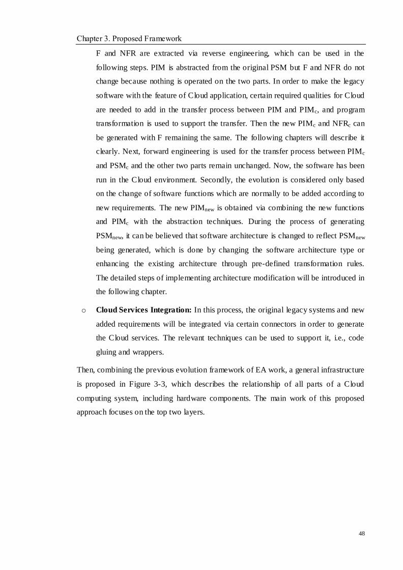
Chapter 3. Proposed Framework
48
F and NFR are extracted via reverse engineering, which can be used in the
following steps. PIM is abstracted from the original PSM but F and NFR do not
change because nothing is operated on the two parts. In order to make the legacy
software with the feature of Cloud application, certain required qualities for Cloud
are needed to add in the transfer process between PIM and PIMc, and program
transformation is used to support the transfer. Then the new PIMc and NFRc can
be generated with F remaining the same. The following chapters will describe it
clearly. Next, forward engineering is used for the transfer process between PIMc
and PSMc and the other two parts remain unchanged. Now, the software has been
run in the Cloud environment. Secondly, the evolution is considered only based
on the change of software functions which are normally to be added according to
new requirements. The new PIMnew is obtained via combining the new functions
and PIMc with the abstraction techniques. During the process of generating
PSMnew, it can be believed that software architecture is changed to reflect PSMnew
being generated, which is done by changing the software architecture type or
enhancing the existing architecture through pre-defined transformation rules.
The detailed steps of implementing architecture modification will be introduced in
the following chapter.
o Cloud Services Integration: In this process, the original legacy systems and new
added requirements will be integrated via certain connectors in order to generate
the Cloud services. The relevant techniques can be used to support it, i.e., code
gluing and wrappers.
Then, combining the previous evolution framework of EA work, a general infrastructure
is proposed in Figure 3-3, which describes the relationship of all parts of a Cloud
computing system, including hardware components. The main work of this proposed
approach focuses on the top two layers.

Chapter 3. Proposed Framework
49
Leg
acy
Sy
stem
An
aly
sis
an
d
Ex
tra
ctio
n
Other Evolution
Approaches
Nec
essa
ry a
nd
Ma
inst
rea
m
La
ng
ua
ge
Sy
stem
s
Decision
No
Yes
Ev
olv
ing
Sy
stem
in
to
Clo
ud
En
vir
on
men
t
Legacy System
PSM
F
NFRReverse
engineer
PIM
F
NFR
Abstract
Required
Qualities for
Cloud
Add new NFF & change PIM
PIMc
F
NFRcTransfer
Forward
engineer
Evo
lvin
g i
nto
Clo
ud
Ev
olv
ing
Sy
stem
wit
hin
Clo
ud
En
vir
on
men
t
PSMnew
Fnew &
NFRc
PIMnew
Fnew &
NFRcTransfer
Change
architecture
New Functions
Add new function & change PIM
PIMc
F
NFRc
PSMc
F
NFRc
Abstract
Become
legacy
Need evolving with new requirements
Evo
lvin
g i
n C
lou
d
Change style
Enhance
architecture
Clo
ud
-Ori
ente
d
Ser
vic
e In
teg
rati
on
Cloud Systems
Wra
pp
er
Tri
gg
erin
g
Op
era
tio
n
FF
un
ctio
ns
NF
RN
on
-Fu
nct
ion
al
Req
uir
emen
ts
= =c
=C
lou
d
Fn
ew=
Co
mp
are
d w
ith
th
e p
rev
iou
s
ver
sio
n
Clo
ud
-Ori
ente
d
Ser
vic
e M
igra
tio
n
Figure 3-2 COE Approach
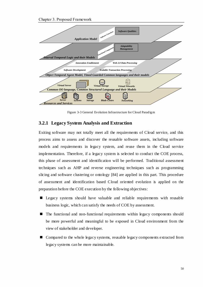
Chapter 3. Proposed Framework
50
Resources and Services
Server Systems Storage NetworkingBlade Centre
Common OO language, Common Structured Language and their Models
Virtual Server Virtual Storage Virtual Networks
Software Development
Object Temporal Agent Model, Timed Guarded Common languages and their models
Innovation Enablement Web 2.0 Data Processing
Scalable Transaction Processing
Interval Temporal Logic and their Models
Application ModelSoftw
are Functions
Functional C
omponents
Software Qualities
Adaptability
Management
Figure 3-3 General Evolution Infrastructure for Cloud Parad igm
3.2.1 Legacy System Analysis and Extraction
Exiting software may not totally meet all the requirements of Cloud service, and this
process aims to assess and discover the reusable software assets, including software
models and requirements in legacy system, and reuse them in the Cloud service
implementation. Therefore, if a legacy system is selected to conduct the COE process,
this phase of assessment and identification will be performed. Traditional assessment
techniques such as AHP and reverse engineering techniques such as programming
slicing and software clustering or ontology [84] are applied in this part. This procedure
of assessment and identification based Cloud oriented evolution is applied on the
preparation before the COE execution by the following objectives:
Legacy systems should have valuable and reliable requirements with reusable
business logic, which can satisfy the needs of COE by assessment.
The functional and non-functional requirements within legacy components should
be more powerful and meaningful to be exposed in Cloud environment from the
view of stakeholder and developer.
Compared to the whole legacy systems, reusable legacy components extracted from
legacy systems can be more maintainable.
Chapter 3. Proposed Framework
51
The acquired Cloud applications can run on different Cloud platforms or vendor
products.
In this part, there are two tasks that are accomplished:
I. Analysis: This needs to decide whether the legacy systems are able to be
selected to move into Cloud environments. The Analytic Hierarchy Process
(AHP) has been popular and widely used for many years, especially in
judgement analysis. It is a mathematical decision-making technique. Although it
has some limitations such as AHP assuming independent criteria and involving
many efforts, it can still be utilised in this paper because the selected criteria
from Cloud features are not many. Utilising AHP, when comparing two styles s1
and s2, a value of 1 is assigned if s1 is equally important as s2, and the value of 9
is represented if s1 is strongly favoured over s2. Values between 1 and 9 indicate
different relationships between two styles. The final stage is to calculate a ratio
to show how consistent the judgements have been relative to large samples of
random judgements. If the radio is much in excess of 0.1 [111], the judgements
are untrustworthy. The detailed content and radio calculation can be required in
[111]. With AHP‘s support, the engineers can make a better decision on whether
the legacy systems can be selected before the practice process. The details will
be discussed in Chapter 4.
II. Legacy Component Extraction: Traditional reverse engineering techniques
will be utilised to understand a software system, i.e., code content, algorithms,
structures and comments. Generally speaking, there are a series of extraction
techniques and capturing, such as program slicing, data mining [54], software
ontology, software clustering, and concept assignment [49] and so on. In this
research, the program slicing technique is used to decompose a system, to
understand a program and requirements, eliminate dead code and make the
selected segment functions with the given criteria. This research also utilises a
software clustering technique that is used to group a large number of code
segments from program slicing and capture reusable legacy components with
software models, software qualities and software functions. The proposed
identification framework in this research includes legacy component unit (LCU),
Chapter 3. Proposed Framework
52
source code segments, requirements information and the relationships among
them, which will be introduced in Chapter 4.
3.2.2 Cloud Oriented Service Migration
After the legacy components analysis and extraction, these components have to be
migrated into a Cloud environment and continue to evolve within Cloud environments
in order to implement Cloud oriented evolution. This part presents the approach for
migrating and evolving legacy components to reuse in Cloud environments.
For the process of evolving into a Cloud environment, assuming legacy software is
valuable to be evolved after the assessment from the features of Cloud such as reliability,
elasticity, adaptability and availability, etc., the process of representing, restructuring,
extracting and transforming has been applied. During the whole operating process, WSL
extension and transformation rules play a very important role in the evolution
procedure.
Code of legacy software mostly includes many redundant information and operations
such as procedure format, string operations, conditional operations, file handling
operations and so on. In order to extract a software model, software functions and
software qualities effectively, WSL extension with WSL semantic is used to represent a
legacy code and complete the domain special analysis. Related transformation rules are
adopted to implement the specification.
With the WSL representation of legacy code, the migration task is prepared to begin.
Abstract Syntax Tree (AST) is used on the WSL representation. For the AST, there are
three types of nodes, Isolated Nodes, Called Nodes only and Calling Others Only. The
isolated nodes can easily be extracted and analysed. The other two nodes are more
difficult to handle. Both bottom-up and top-down approaches can help to deal with these
two nodes. The bottom-up method will be effective to find the called nodes, while the
top-down method will be able to deal with the calling ones. Utilising them together can
provide support to each other and avoids incomplete extractions. Meanwhile, the two
slicing algorithms are proposed to extract reusable models, function components and
other valuable information during the process of bottom-up and top-down. After the

Chapter 3. Proposed Framework
53
extraction, the reusable models are wrapped and marked as Classes, Procedures, or
Actions by WSL, which can be used as the following transformation phase.
The representation, specification and extraction, PSM, functional components and NFR
of legacy software have now been extracted. To implement the evolution into a Cloud
environment, the more abstract PIM is better to complete the evolution, because the
special context has been reduced and new requirements from NFR of a Cloud
environment can be added into PIM. During this phase, the three-dimensional parts will
change software model and NFR but keep the software function. There are two stages
that include transferring requirements in PIM and transferring PIM to PSM. The
transformation rules are defined to guide the transformation process.
The following stage that can be seen in Figure 3-2, which also includes the process of
evolving within a Cloud environment, is how to handle the evolution after the legacy
components are migrated into the Cloud environment. This process begins with the
acquired PSM in the last phase. In this phase, the legacy components have got the
required Cloud features and hence NFR will not change. This stage will be completed
through software model and software functions. When new functions are needed, the
transformation will still be applied between PIM and PSM. WSL is also utilised to
restructure the applications in the Cloud paradigms. As known, non-functional
requirements are much easier to add and improve the code change without the
modification of the whole system architecture. However, it will be hard to handle
software function change with software models. Once new functions are needed by
applications in a Cloud paradigm, software architecture may require changing, too.
Therefore, this part chooses to use how to change software architecture to fulfil the final
implementation. Considering changing architecture style [42] or enhancing architecture
has been proposed in Section 5.3.2.1. Currently, there are few researches that discuss
how to transform architecture style to fulfil the functions changes. This thes is proposes
a novel approach for transforming the architecture style based on previous works[149,
156]. A decision-making algorithm on how to choose architecture style and the related
transformation rules will be depicted in detail in the following chapters. Finally, the
whole evolution into and within a Cloud environment will recur if the system becomes
legacy or a new function or NFR is needed. All the processes will be supported by EA

Chapter 3. Proposed Framework
54
toolkit, and the acquired service will be integrated in Chapter 6.
3.2.3 Cloud-Oriented Service Integration
Generally speaking, Cloud service integration is fairly straightforward. The extracted
and reimplemented legacy system components can be wrapped and integrated into
preferable service architecture, i.e., Cloud oriented architecture (COA) and
Service-oriented architecture (SOA). In this study, the legacy services and
reimplementation services can be composed via built connectors in order to construct
the target system. Interface building, wrapper and code gluing techniques can be utilised
to implement this process. XML, WSDL and Java can be applied to wrap, build and
implement the needs. The more detailed integration will not be discussed in this thesis
because this research mainly focused on the issue of evolving the legacy services into
and within a Cloud paradigm. In other words, the integration techniques can easily be
adopted through the existing research. During this phase, the COA has been given in
Figure 3-4. The related introduction will be described in Chapter 7 and the processes of
how to wrap service and build and invoke interface will be also discussed. Meanwhile,
that chapter also discusses the integration on two types of Cloud paradigms such as a
public and a private one, which can be representative to prove the proposed approach
can satisfy the requirements of current enterprise.
Legacy Application
Interface ManangementWrapper
Service Integrate Cloud Platforms
Security
Admission
control
Task Management
Scheduling Mapping
Computing Deploying
Resource Management
Distribution Computing
Storage Statistics
Mon
itoring
User Management
Tools
Accounting
Records
Figure 3-4 Proposed Cloud Oriented Architecture
Chapter 3. Proposed Framework
55
3.3 Summary
The necessity of establishing the reusing of legacy components is discussed. The
concerned COE is defined, which could include two parts in the migration process. One
is how to evolve a legacy system into a Cloud environment and the other is how to
implement the evolution within a Cloud environment. Meanwhile, the related work is
also introduced
According to the requirement analysis, a novel COE approach has been proposed in this
chapter. This approach mainly contains three stages, which are the assessment and
identification stage, service reimplementation stage, and service integration stage. Some
domain logic analysis and assessment methods, software reengineering (a combination
of reverse engineering and forward engineering) methods, and intelligent information
process methods and techniques (such as knowledge representation, abstraction,
programming transformation, etc.) are applied to implement COE projects:
Analysis and legacy component extraction, - this is the process of assessing whether
legacy system is valuable to start the evolution, and identifying reusable
components from legacy systems, i.e., a series of class code segments, functional
components and non-functional requirements of a system. Through the
identification process, the recovery of models, functions and NFR can be extracted
from source code. If this process cannot be conducted, the following evolution will
be hindered. The understanding and composition of components are adopted to
implement the identification. Related techniques and proposed algorithms are used
to support the implementation. The acquired results will be prepared to start the
next stages.
Cloud-oriented service migration, - the software reengineering techniques that
contain reverse engineering and forward engineering are composed to complete the
evolution task. A three-dimensional software evolution paradigm is proposed to
satisfy the complex Cloud computing paradigm, which is discussed from the three
dimensions, software model, software qualities and software functions. To
guarantee the evolution process is completed for a Cloud environment, two phases
in this stage are proposed. One is to migrate the legacy component into the Cloud
Chapter 3. Proposed Framework
56
environment and to consider the changes between software models and software
qualities but to keep the software functions. The other is to continue to evolve
within the Cloud environment once the software function and software model have
improved with the fixed software qualities. Furthermore, the rules for model
transformation and architecture change, and the supported algorithms are defined in
the whole process. Meanwhile, the general evolution infrastructure for Cloud
paradigm based EA is also proposed to be given in this part.
Typically, how to evolve the legacy system into and within a Cloud environment is
crucial since it is important to choose the appropriate programming languages for
the representation and the satisfied software architecture style. To facilitate the two
complex tasks, an extension based WSL is developed to represent the legacy system
and complete the transformation with relevant rules. It can embrace the efficient
libraries for specifying the reusable legacy services. Moreover, the discussion on
architecture style and the choice on deciding architecture style change are first
drawn into the process of architecture change and the method for style selection is
proposed to support the decision.
Cloud-oriented services integration, - it is the final stage where newly built services
and the existing services can be integrated together and involved to serve the users
and enterprise. How to define the service interface and to implement it will be
depicted and the COA is proposed. Different types of Cloud platforms are chosen to
prove the integration is adaptive.
The proposed approach has been regarded as a semi-automatic process that involves
a series of manual work on the representation from domain analysis, and automatic
transformation with defined rules can be implemented with tool support. For
quantitative methods of this work, these are reflected by completing the
reimplementation step of the chosen legacy system with relevant programming
language support to generalize the results. For qualitative methods of this work,
these respond to the assessment and identification about why and what related
questions are discussed.
Chapter 4. Legacy System Analysis and Extraction
57
Chapter 4 Legacy System Analysis and
Extraction
Objectives
__________________________________________________________________
To introduce the process of legacy system analysis.
To propose an AHP based on Cloud features for determining feasibility of
legacy components.
To describe the process of legacy system Extraction.
To present the slicing rules and algorithms for obtaining reusable legacy assets.
To retarget reusable legacy components for evolution.
__________________________________________________________________
4.1 Overview
In Cloud computing development, software requirements and implementation will
sometimes seem reconciled. This leads to difficulties for software evolution tasks in
Cloud computing environments. In general, for Cloud applications, the required Cloud
features imply that migrating existing legacy systems into a Cloud environment needs to
decide whether the legacy components are able to satisfy the corresponding features of
the Cloud. Some outdated systems may not be suitable to evolve since a lot of effort is
needed to be applied to them and developing new systems can fulfil the requirements of
stakeholders and business. Therefore, it is very important to make an assessment that
helps the choice on selecting the applicable legacy systems for the evolution. During the
assessment process in this chapter, many criteria and sub criteria are required to rank the
alternatives of the decisions. To decide whether the legacy components can evolve into
Cloud applications, the related criteria should have a relationship with the Cloud
features, NFR and stakeholders‘ requirements. In order to weigh the priorities of the
alternatives on the selected criteria, the selection of suitable computing techniques is
Chapter 4. Legacy System Analysis and Extraction
58
still a challenging task. In this task, an assessment framework based on relevant
requirements is built and the assessment process is described.
On the other hand, reverse engineering, a well-known technique in software engineering,
aims to understand and identify the functions and behaviour of a legacy system through
a source code. Identifying the legacy systems is used to extract reusable existing
components. Analysis and decomposition are included in this process. In order to
discover the reusable information and prepare for the following evolution, the improved
program slicing techniques and software clustering techniques are applied on the mining
process in this chapter.
4.2 Legacy System Analysis
4.2.1 The Problem
As introduced in Chapter 2, a legacy system is the system that was developed in the past
or has become outdated in the business area. Typically, many systems become legacy
because of modern software engineering methods‘ use and dynamic requirement change.
In order to implement the reuse of them, the assessment and understanding of legacy
components are very crucial in the beginning stage of the evolution. Software
assessment has been used to obtain an understanding of a legacy system, which is
suitable for any approach to software evolution. The assessment method can judge and
decide the evolution from a system‘s technical quality, internal requirements, external
requirements and its required characteristics.
Making decisions about the assessment of a legacy system has become one initial
concern for those enterprises that own the legacy systems. Therefore, it is necessary to
address problems concerning the choice of the supporting legacy software systems, e.g.,
choosing legacy systems and migrating them into Cloud environments. The aim is to
integrate the legacy systems with required business requirements and reuse them to
reduce the cost and time of developing. However, many existing approaches do not
consider the decision strategy in the evolution process. They only regard the legacy
system evolution as a stand-alone problem. In fact, the software evolution can be caused
by mediations in business processes and by keeping them usable in a changed or
Chapter 4. Legacy System Analysis and Extraction
59
changing environment. Hence it cannot be avoided without deciding whether these
modifications are valuable. To assist the legacy system assessment to fulfil those
modifications based on Cloud features, an assessment method based on AHP technique
is proposed to complete the legacy system assessment from the related aspects, i.e.,
internal requirements, external requirements and business values.
4.2.2 Proposed Assessment Method
4.2.2.1 AHP Technique
The analytic hierarchy process (AHP) has been regarded as a structured technique for
organising and analysing complex decisions. It was developed by Thomas L in the
1970s [112], which is based on mathematics and psychology, and it has been studied
and refined by many researchers since then. It is a theory of measurement through
complex comparisons to get the priority scales which can be used to judge the final
decisions. The technique has been used widely in many fields, such as business,
industry, education and so on. Using AHP will help the decision makers find the result
that best suits their goal and their understanding of a detailed problem. It provides a
comprehensive and rational framework for structuring a decision to represent and
quantify its elements, which have the relationships with those elements and alternative
solutions. Once the hierarchy is built, the decision makers can systematically assess its
various elements by comparing them through converting those evaluations to number
values, calculating the number values, and using the priorities gained from the
comparisons to decide whether these criteria can achieve their goal. During the process
of making the comparisons, the decision makers cannot only use concrete data about the
elements based on the selected criteria, but also they typically use their judgment about
the elements' relative meaning and importance from the expert‘s advice and business
activities. With its advantages, legacy system assessment can adopt AHP to evaluate
and decide the feasibility and value on evolving them into a Cloud computing
environment. This thesis utilises it to implement the assessment objective and to
propose the assessment method based on AHP.
In order to know about AHP, the general procedure is introduced as follows:
1. Define the problem and model it as a hierarchy, which includes the decision goal,
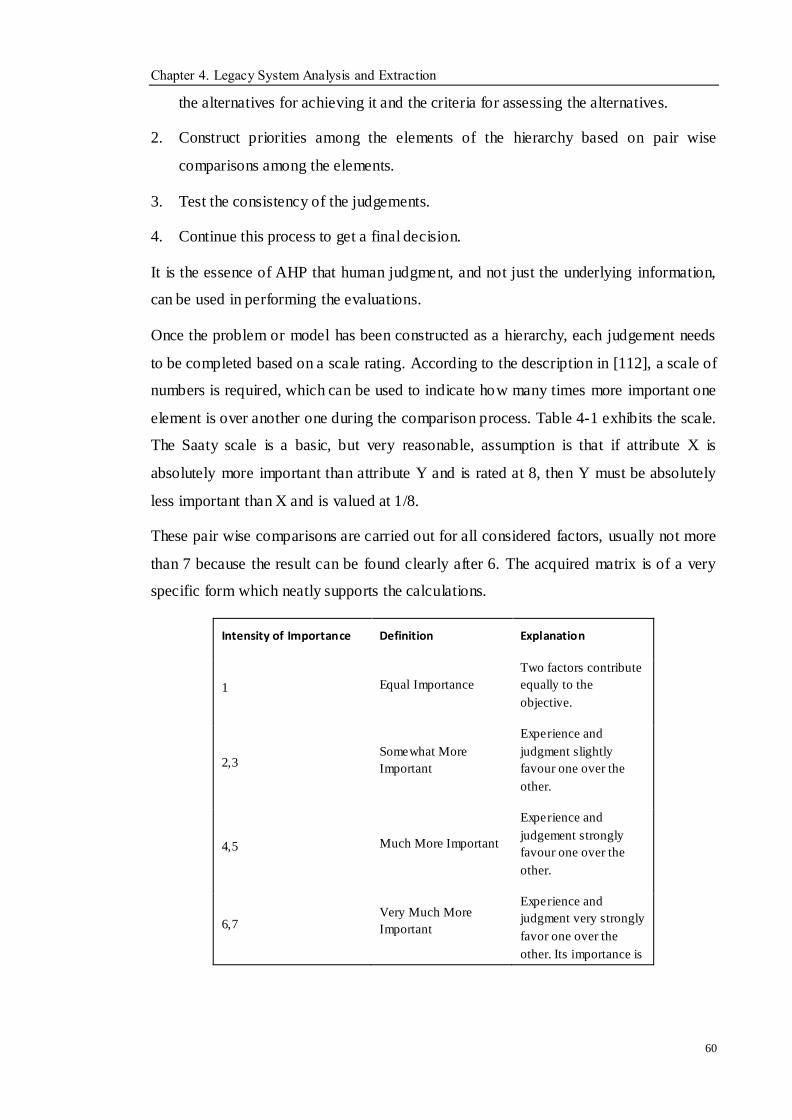
Chapter 4. Legacy System Analysis and Extraction
60
the alternatives for achieving it and the criteria for assessing the alternatives.
2. Construct priorities among the elements of the hierarchy based on pair wise
comparisons among the elements.
3. Test the consistency of the judgements.
4. Continue this process to get a final decision.
It is the essence of AHP that human judgment, and not just the underlying information,
can be used in performing the evaluations.
Once the problem or model has been constructed as a hierarchy, each judgement needs
to be completed based on a scale rating. According to the description in [112], a scale of
numbers is required, which can be used to indicate how many times more important one
element is over another one during the comparison process. Table 4-1 exhibits the scale.
The Saaty scale is a basic, but very reasonable, assumption is that if attribute X is
absolutely more important than attribute Y and is rated at 8, then Y must be absolutely
less important than X and is valued at 1/8.
These pair wise comparisons are carried out for all considered factors, usually not more
than 7 because the result can be found clearly after 6. The acquired matrix is of a very
specific form which neatly supports the calculations.
Intensity of Importance Definition Explanation
1 Equal Importance
Two factors contribute
equally to the
objective.
2,3 Somewhat More
Important
Experience and
judgment slightly
favour one over the
other.
4,5 Much More Important
Experience and
judgement strongly
favour one over the
other.
6,7 Very Much More
Important
Experience and
judgment very strongly
favor one over the
other. Its importance is
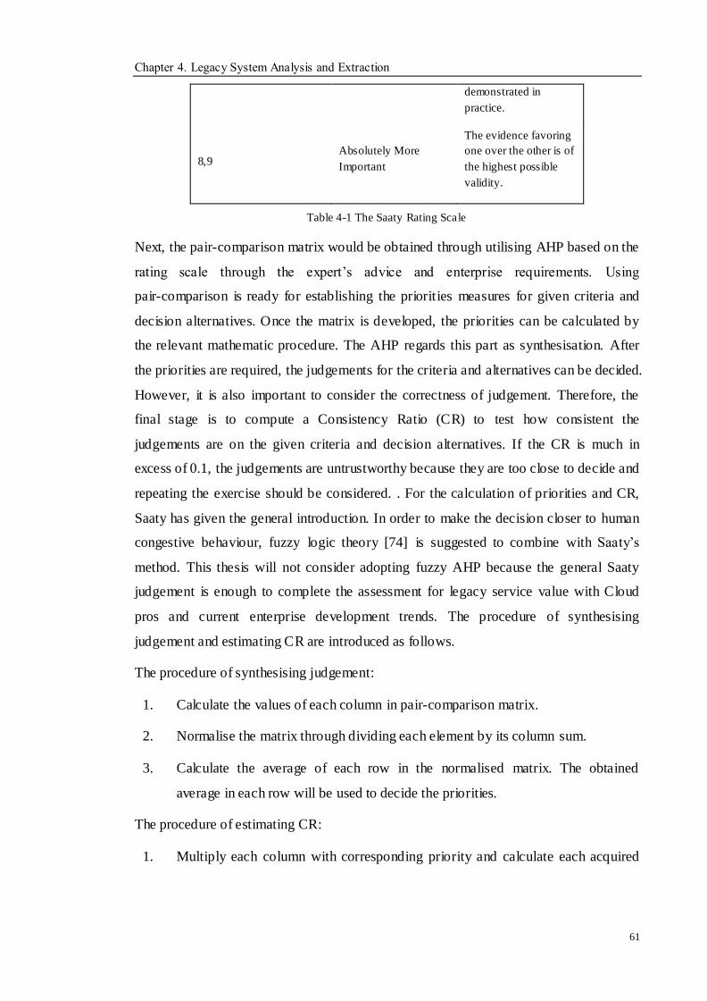
Chapter 4. Legacy System Analysis and Extraction
61
demonstrated in
practice.
8,9 Absolutely More
Important
The evidence favoring
one over the other is of
the highest possible
validity.
Table 4-1 The Saaty Rating Scale
Next, the pair-comparison matrix would be obtained through utilising AHP based on the
rating scale through the expert‘s advice and enterprise requirements. Using
pair-comparison is ready for establishing the priorities measures for given criteria and
decision alternatives. Once the matrix is developed, the priorities can be calculated by
the relevant mathematic procedure. The AHP regards this part as synthesisation. After
the priorities are required, the judgements for the criteria and alternatives can be decided.
However, it is also important to consider the correctness of judgement. Therefore, the
final stage is to compute a Consistency Ratio (CR) to test how consistent the
judgements are on the given criteria and decision alternatives. If the CR is much in
excess of 0.1, the judgements are untrustworthy because they are too close to decide and
repeating the exercise should be considered. . For the calculation of priorities and CR,
Saaty has given the general introduction. In order to make the decision closer to human
congestive behaviour, fuzzy logic theory [74] is suggested to combine with Saaty‘s
method. This thesis will not consider adopting fuzzy AHP because the general Saaty
judgement is enough to complete the assessment for legacy service value with Cloud
pros and current enterprise development trends. The procedure of synthesising
judgement and estimating CR are introduced as follows.
The procedure of synthesising judgement:
1. Calculate the values of each column in pair-comparison matrix.
2. Normalise the matrix through dividing each element by its column sum.
3. Calculate the average of each row in the normalised matrix. The obtained
average in each row will be used to decide the priorities.
The procedure of estimating CR:
1. Multiply each column with corresponding priority and calculate each acquired
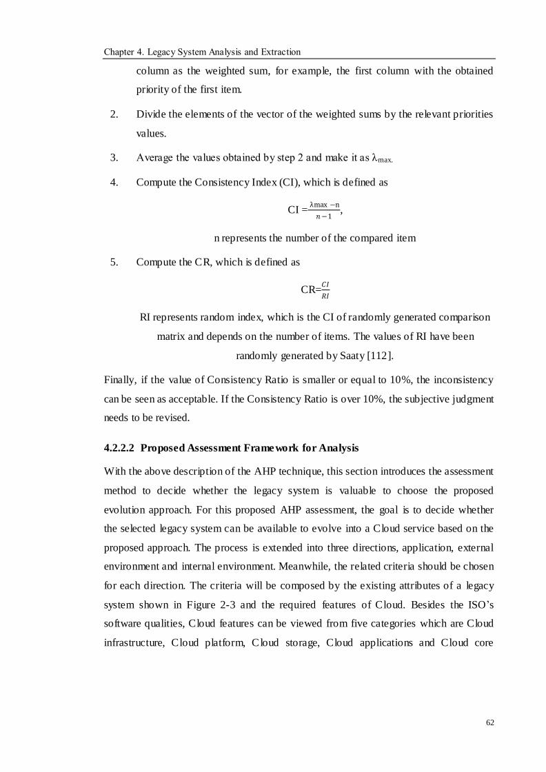
Chapter 4. Legacy System Analysis and Extraction
62
column as the weighted sum, for example, the first column with the obtained
priority of the first item.
2. Divide the elements of the vector of the weighted sums by the relevant priorities
values.
3. Average the values obtained by step 2 and make it as λmax.
4. Compute the Consistency Index (CI), which is defined as
CI = λmax −n
𝑛−1,
n represents the number of the compared item
5. Compute the CR, which is defined as
CR=𝐶𝐼
𝑅𝐼
RI represents random index, which is the CI of randomly generated comparison
matrix and depends on the number of items. The values of RI have been
randomly generated by Saaty [112].
Finally, if the value of Consistency Ratio is smaller or equal to 10%, the inconsistency
can be seen as acceptable. If the Consistency Ratio is over 10%, the subjective judgment
needs to be revised.
4.2.2.2 Proposed Assessment Framework for Analysis
With the above description of the AHP technique, this section introduces the assessment
method to decide whether the legacy system is valuable to choose the proposed
evolution approach. For this proposed AHP assessment, the goal is to decide whether
the selected legacy system can be available to evolve into a Cloud service based on the
proposed approach. The process is extended into three directions, application, external
environment and internal environment. Meanwhile, the related criteria should be chosen
for each direction. The criteria will be composed by the existing attributes of a legacy
system shown in Figure 2-3 and the required features of Cloud. Besides the ISO‘s
software qualities, Cloud features can be viewed from five categories which are Cloud
infrastructure, Cloud platform, Cloud storage, Cloud applications and Cloud core

Chapter 4. Legacy System Analysis and Extraction
63
solutions.
Cloud infrastructure is regarded as virtual servers in the Cloud. It can support the
large-scale applications or processes. For large-scale applications, Myspace or
Facebook; for large-scale processing, running test simulations for automobile
manufacturing or aircraft. The most important advantage is the virtualisation,
thereby removing the need to purchase or maintain hardware.
Cloud platform has the ability to build, deploy, test, run, and handle applications
in the Cloud. It is a highly-scalable and low-cost development environment for
Web-based applications and services. It is feasible to consider Cloud platforms as a
highly developed structure of Web hosting, with more scalability and availability
than the normal Web-host type.
Cloud Storage mentions any type of data storage that can be placed in the Cloud. It
offers a series of benefits, i.e., the ability to store and recover large amounts of data
in any location at any time. The services are inexpensive, fast and almost infinitely
scalable; however, there are issues which also exist, such as reliability when even
the best services sometimes fail, and the transaction support that needs to be widely
used in business.
Cloud applications exist either partially or fully within the Cloud, and utilises
Cloud services to realise centre features within the application. It can often
eliminate the need to install and run the application locally, thereby reducing the
cost and time for software maintenance, deployment and management. SaaS is the
main type used for Cloud applications, and rich clients can be installed on a PC to
interact with external services.
Cloud core solutions can support Cloud-based services, such as identity
management, mapping, search, service-to-service integration, business process
management, and so on. They may have the potential to replace existing service
models in the future.
Each category above also has a series of Cloud attributes. When the developers decide
to migrate the legacy system into Cloud computing environments, these Cloud attributes
are very vital standards for the proposed project. There are two aspects that have been
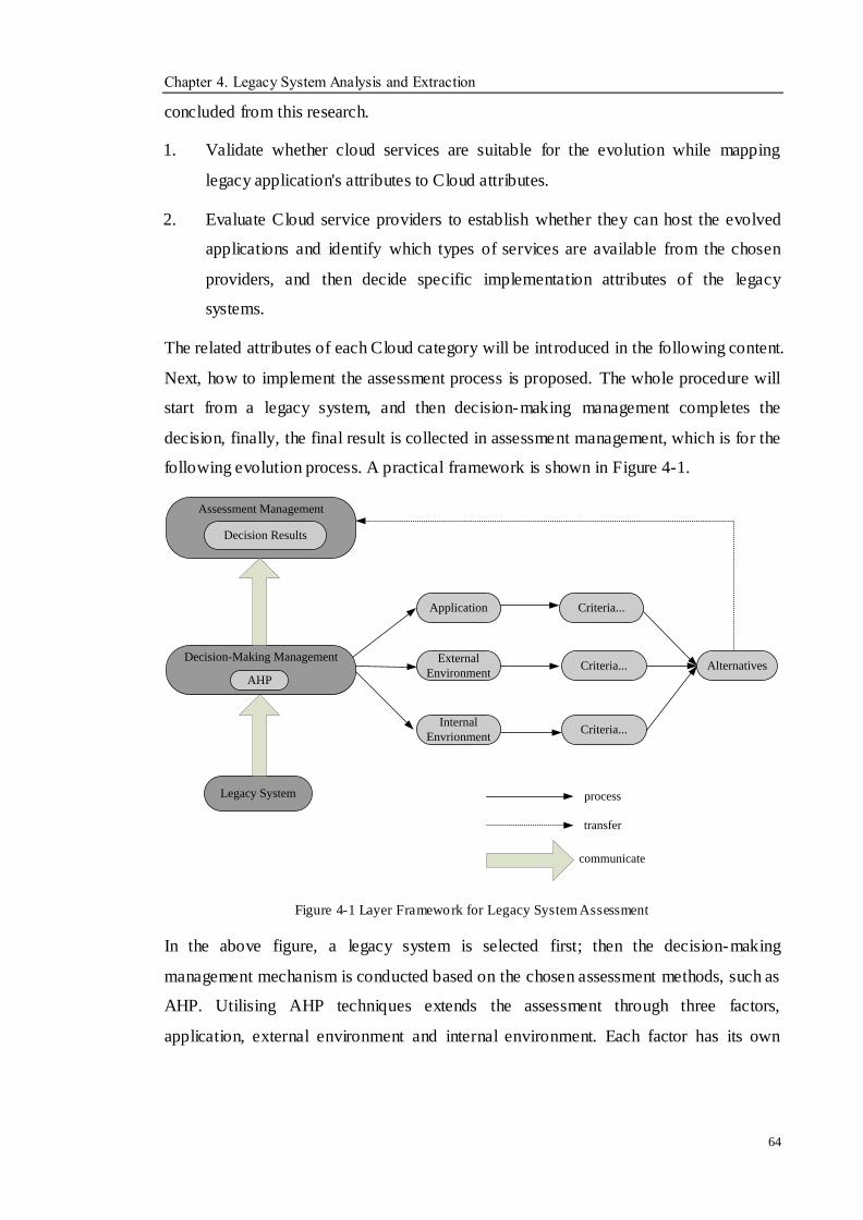
Chapter 4. Legacy System Analysis and Extraction
64
concluded from this research.
1. Validate whether cloud services are suitable for the evolution while mapping
legacy application's attributes to Cloud attributes.
2. Evaluate Cloud service providers to establish whether they can host the evolved
applications and identify which types of services are available from the chosen
providers, and then decide specific implementation attributes of the legacy
systems.
The related attributes of each Cloud category will be introduced in the following content.
Next, how to implement the assessment process is proposed. The whole procedure will
start from a legacy system, and then decision-making management completes the
decision, finally, the final result is collected in assessment management, which is for the
following evolution process. A practical framework is shown in Figure 4-1.
Legacy System
Decision-Making Management
AHP
Assessment Management
Decision Results
Application
External
Environment
Internal
Envrionment
Criteria...
Criteria...
Criteria...
Alternatives
process
transfer
communicate
Figure 4-1 Layer Framework for Legacy System Assessment
In the above figure, a legacy system is selected first; then the decision-making
management mechanism is conducted based on the chosen assessment methods, such as
AHP. Utilising AHP techniques extends the assessment through three factors,
application, external environment and internal environment. Each factor has its own
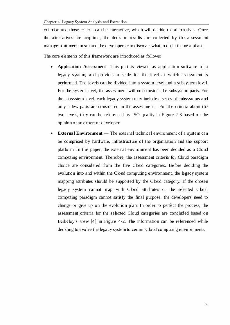
Chapter 4. Legacy System Analysis and Extraction
65
criterion and those criteria can be interactive, which will decide the alternatives. Once
the alternatives are acquired, the decision results are collected by the assessment
management mechanism and the developers can discover what to do in the next phase.
The core elements of this framework are introduced as follows:
Application Assessment—This part is viewed as application software of a
legacy system, and provides a scale for the level at which assessment is
performed. The levels can be divided into a system level and a subsystem level.
For the system level, the assessment will not consider the subsystem parts. For
the subsystem level, each legacy system may include a series of subsystems and
only a few parts are considered in the assessment. For the criteria about the
two levels, they can be referenced by ISO quality in Figure 2-3 based on the
opinion of an expert or developer.
External Environment — The external technical environment of a system can
be comprised by hardware, infrastructure of the organisation and the support
platform. In this paper, the external environment has been decided as a Cloud
computing environment. Therefore, the assessment criteria for Cloud paradigm
choice are considered from the five Cloud categories. Before deciding the
evolution into and within the Cloud computing environment, the legacy system
mapping attributes should be supported by the Cloud category. If the chosen
legacy system cannot map with Cloud attributes or the selected Cloud
computing paradigm cannot satisfy the final purpose, the developers need to
change or give up on the evolution plan. In order to perfect the process, the
assessment criteria for the selected Cloud categories are concluded based on
Berkeley‘s view [4] in Figure 4-2. The information can be referenced while
deciding to evolve the legacy system to certain Cloud computing environments.
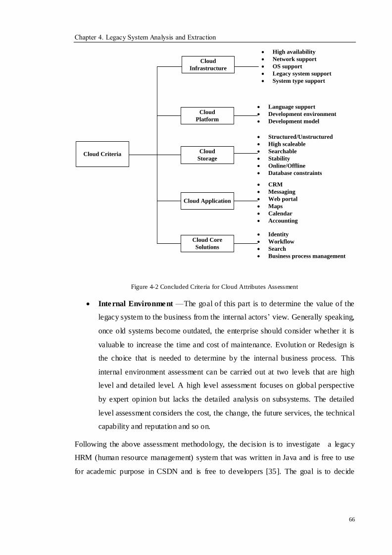
Chapter 4. Legacy System Analysis and Extraction
66
Cloud
Infrastructure
Cloud
Platform
Cloud
Storage
Cloud Application
Cloud Core
Solutions
Cloud Criteria
High availability
Network support
OS support
Legacy system support
System type support
Language support
Development environment
Development model
Structured/Unstructured
High scaleable
Searchable
Stability
Online/Offline
Database constraints
CRM
Messaging
Web portal
Maps
Calendar
Accounting
Identity
Workflow
Search
Business process management
Figure 4-2 Concluded Criteria for Cloud Attributes Assessment
Internal Environment —The goal of this part is to determine the value of the
legacy system to the business from the internal actors‘ view. Generally speaking,
once old systems become outdated, the enterprise should consider whether it is
valuable to increase the time and cost of maintenance. Evolution or Redesign is
the choice that is needed to determine by the internal business process. This
internal environment assessment can be carried out at two levels that are high
level and detailed level. A high level assessment focuses on global perspective
by expert opinion but lacks the detailed analysis on subsystems. The detailed
level assessment considers the cost, the change, the future services, the technical
capability and reputation and so on.
Following the above assessment methodology, the decision is to investigate a legacy
HRM (human resource management) system that was written in Java and is free to use
for academic purpose in CSDN and is free to developers [35]. The goal is to decide
Chapter 4. Legacy System Analysis and Extraction
67
whether the HRM system can be selected to implement the Cloud service. Figure 4-3
gives the process of the proposed assessment approach on a practical project. It is
important to discuss the criteria in the figure for the HRM in a Cloud environment [105],
the AHP Hierarchy is built and the final decision is obtained by the mathematic
computation.
Migrating HRM to Cloud
System Factors Cloud Factors Business Factors
Per
form
ance
Fu
nct
ion
alit
y
Fle
xib
ilit
y
Rel
iab
ilit
y
Rel
iab
ilit
y
OS
Su
pp
ort
Sea
rch
able
Ser
vic
es
Cap
abil
ity
Rep
uta
tio
n
Evolution Partly Evolution Redesign
Figure 4-3 AHP Assessment Hierarchy
In the above figure, three alternatives have been listed, which are full evolution, partly
evolution and redesign. Each alternative is affected by ten criteria. According to Saaty‘s
method, paired comparisons of the alternatives on each criteria can be made and
converted to the scale of 1-9 based on expert opinion or business experience on HRM
[105]. The normalised weights and synthesised results can be calculated based on
Saaty‘s theory. The detailed computation procedure is not described here and more
information can be found in Saaty‘s work. There are ten comparison matrices for the
three alternatives with respect to all the criteria. The paper shows one of these ten
matrices comparing the alternatives with respect to the criterion for improved
―Performance‖ of ERP in Table 4-2, Table 4-3 and Table 4-4. The other criteria have
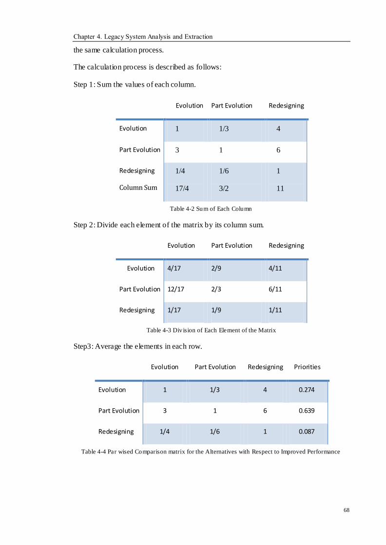
Chapter 4. Legacy System Analysis and Extraction
68
the same calculation process.
The calculation process is described as follows:
Step 1: Sum the values of each column.
Evolution Part Evolution Redesigning
Evolution 1 1/3 4
Part Evolution 3 1 6
Redesigning
Column Sum
1/4
17/4
1/6
3/2
1
11
Table 4-2 Sum of Each Column
Step 2: Divide each element of the matrix by its column sum.
Evolution Part Evolution Redesigning
Evolution 4/17 2/9 4/11
Part Evolution 12/17 2/3 6/11
Redesigning 1/17 1/9 1/11
Table 4-3 Div ision of Each Element of the Matrix
Step3: Average the elements in each row.
Evolution Part Evolution Redesigning Priorities
Evolution 1 1/3 4 0.274
Part Evolution 3 1 6 0.639
Redesigning 1/4 1/6 1 0.087
Table 4-4 Par wised Comparison matrix for the Alternatives with Respect to Improved Performance
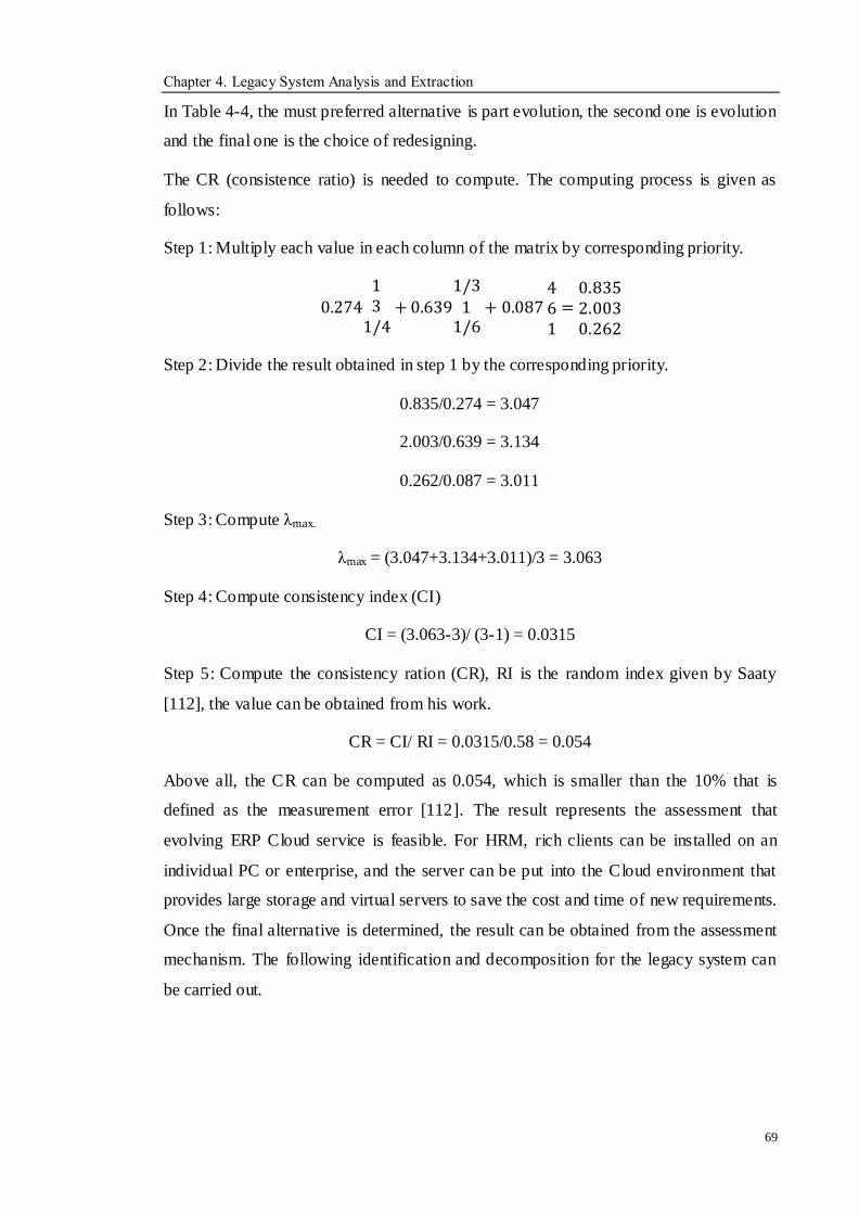
Chapter 4. Legacy System Analysis and Extraction
69
In Table 4-4, the must preferred alternative is part evolution, the second one is evolution
and the final one is the choice of redesigning.
The CR (consistence ratio) is needed to compute. The computing process is given as
follows:
Step 1: Multiply each value in each column of the matrix by corresponding priority.
0.274
13
1/4+ 0.639
1/3
11/6
+ 0.087 461
=0.8352.0030.262
Step 2: Divide the result obtained in step 1 by the corresponding priority.
0.835/0.274 = 3.047
2.003/0.639 = 3.134
0.262/0.087 = 3.011
Step 3: Compute λmax.
λmax = (3.047+3.134+3.011)/3 = 3.063
Step 4: Compute consistency index (CI)
CI = (3.063-3)/ (3-1) = 0.0315
Step 5: Compute the consistency ration (CR), RI is the random index given by Saaty
[112], the value can be obtained from his work.
CR = CI/ RI = 0.0315/0.58 = 0.054
Above all, the CR can be computed as 0.054, which is smaller than the 10% that is
defined as the measurement error [112]. The result represents the assessment that
evolving ERP Cloud service is feasible. For HRM, rich clients can be installed on an
individual PC or enterprise, and the server can be put into the Cloud environment that
provides large storage and virtual servers to save the cost and time of new requirements.
Once the final alternative is determined, the result can be obtained from the assessment
mechanism. The following identification and decomposition for the legacy system can
be carried out.
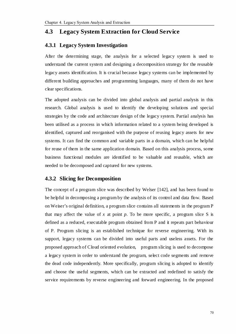
Chapter 4. Legacy System Analysis and Extraction
70
4.3 Legacy System Extraction for Cloud Service
4.3.1 Legacy System Investigation
After the determining stage, the analysis for a selected legacy system is used to
understand the current system and designing a decomposition strategy for the reusable
legacy assets identification. It is crucial because legacy systems can be implemented by
different building approaches and programming languages, many of them do not have
clear specifications.
The adopted analysis can be divided into global analysis and partial analysis in this
research. Global analysis is used to identify the developing solutions and special
strategies by the code and architecture design of the legacy system. Partial analysis has
been utilised as a process in which information related to a system being developed is
identified, captured and reorganised with the purpose of reusing legacy assets for new
systems. It can find the common and variable parts in a domain, which can be helpful
for reuse of them in the same application domain. Based on this analysis process, some
business functional modules are identified to be valuable and reusable, which are
needed to be decomposed and captured for new systems.
4.3.2 Slicing for Decomposition
The concept of a program slice was described by Welser [142], and has been found to
be helpful in decomposing a program by the analysis of its control and data flow. Based
on Weiser‘s original definition, a program slice contains all statements in the program P
that may affect the value of x at point p. To be more specific, a program slice S is
defined as a reduced, executable program obtained from P and it repeats part behaviour
of P. Program slicing is an established technique for reverse engineering. With its
support, legacy systems can be divided into useful parts and useless assets. For the
proposed approach of Cloud oriented evolution, program slicing is used to decompose
a legacy system in order to understand the program, select code segments and remove
the dead code independently. More specifically, program slicing is adopted to identify
and choose the useful segments, which can be extracted and redefined to satisfy the
service requirements by reverse engineering and forward engineering. In the proposed
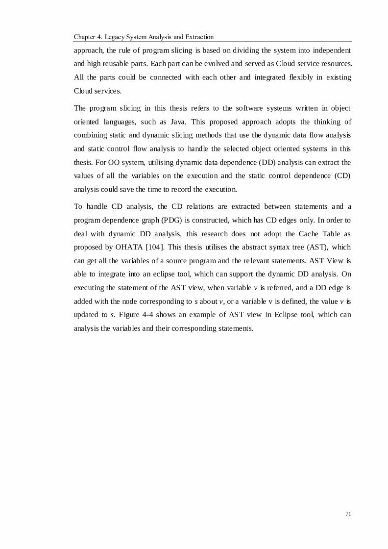
Chapter 4. Legacy System Analysis and Extraction
71
approach, the rule of program slicing is based on dividing the system into independent
and high reusable parts. Each part can be evolved and served as Cloud service resources.
All the parts could be connected with each other and integrated flexibly in existing
Cloud services.
The program slicing in this thesis refers to the software systems written in object
oriented languages, such as Java. This proposed approach adopts the thinking of
combining static and dynamic slicing methods that use the dynamic data flow analysis
and static control flow analysis to handle the selected object oriented systems in this
thesis. For OO system, utilising dynamic data dependence (DD) analysis can extract the
values of all the variables on the execution and the static control dependence (CD)
analysis could save the time to record the execution.
To handle CD analysis, the CD relations are extracted between statements a nd a
program dependence graph (PDG) is constructed, which has CD edges only. In order to
deal with dynamic DD analysis, this research does not adopt the Cache Table as
proposed by OHATA [104]. This thesis utilises the abstract syntax tree (AST), which
can get all the variables of a source program and the re levant statements. AST View is
able to integrate into an eclipse tool, which can support the dynamic DD analysis. On
executing the statement of the AST view, when variable v is referred, and a DD edge is
added with the node corresponding to s about v, or a variable v is defined, the value v is
updated to s. Figure 4-4 shows an example of AST view in Eclipse tool, which can
analysis the variables and their corresponding statements.
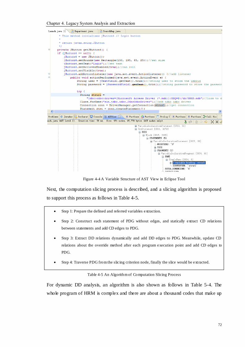
Chapter 4. Legacy System Analysis and Extraction
72
Figure 4-4 A Variable Structure of AST View in Eclipse Tool
Next, the computation slicing process is described, and a slicing algorithm is proposed
to support this process as follows in Table 4-5.
Step 1: Prepare the defined and referred variables extraction.
Step 2: Construct each statement of PDG without edges, and statically extract CD relat ions
between statements and add CD edges to PDG.
Step 3: Extract DD relations dynamically and add DD edges to PDG. Meanwhile, update CD
relations about the override method after each program execution point and add CD edges to
PDG.
Step 4: Traverse PDG from the slicing criterion node, finally the slice would be ext racted.
Table 4-5 An Algorithm of Computation Slicing Process
For dynamic DD analysis, an algorithm is also shown as follows in Table 5-4. The
whole program of HRM is complex and there are about a thousand codes that make up
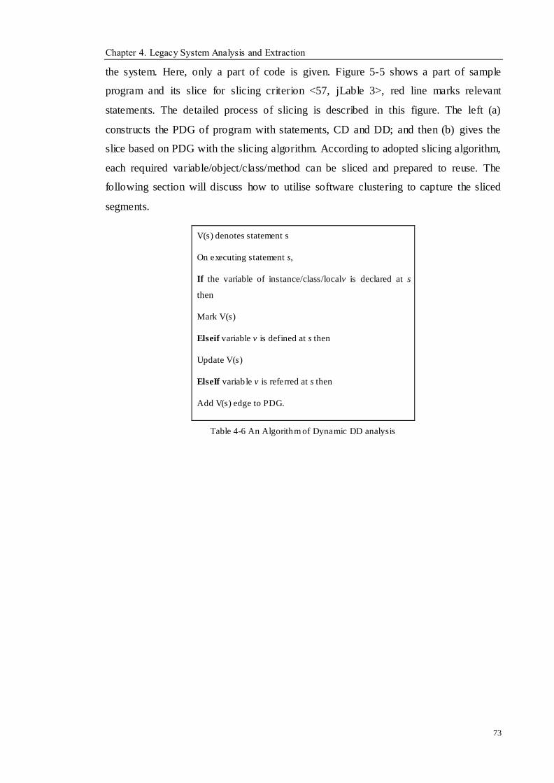
Chapter 4. Legacy System Analysis and Extraction
73
the system. Here, only a part of code is given. Figure 5-5 shows a part of sample
program and its slice for slicing criterion <57, jLable 3>, red line marks relevant
statements. The detailed process of slicing is described in this figure. The left (a)
constructs the PDG of program with statements, CD and DD; and then (b) gives the
slice based on PDG with the slicing algorithm. According to adopted slicing algorithm,
each required variable/object/class/method can be sliced and prepared to reuse. The
following section will discuss how to utilise software clustering to capture the sliced
segments.
V(s) denotes statement s
On executing statement s,
If the variable of instance/class/localv is declared at s
then
Mark V(s)
Elseif variable v is defined at s then
Update V(s)
ElseIf variab le v is referred at s then
Add V(s) edge to PDG.
Table 4-6 An Algorithm of Dynamic DD analysis
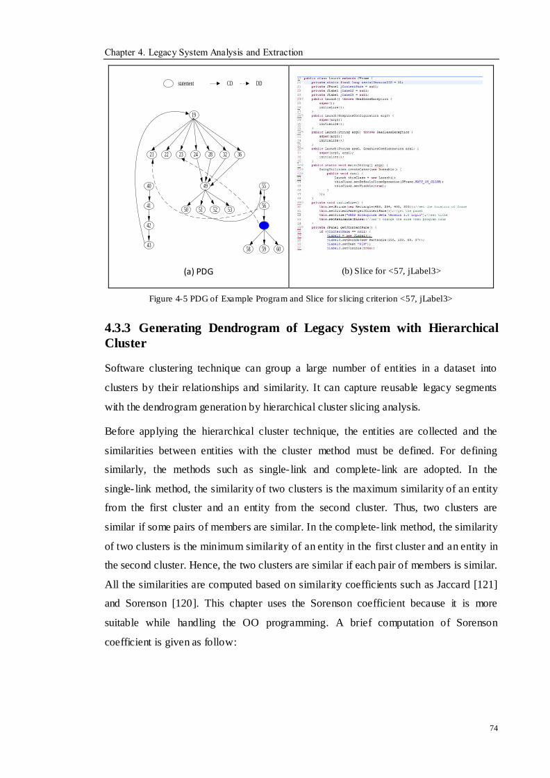
Chapter 4. Legacy System Analysis and Extraction
74
21
51
55
56
57
58 59 60
49
2823
statement CD DD
22 24 3632
19
40
41
42
50 52 53
43
(a) PDG
(b) Slice for <57, jLabel3>
Figure 4-5 PDG of Example Program and Slice for slicing criterion <57, jLabel3>
4.3.3 Generating Dendrogram of Legacy System with Hierarchical
Cluster
Software clustering technique can group a large number of entities in a dataset into
clusters by their relationships and similarity. It can capture reusable legacy segments
with the dendrogram generation by hierarchical cluster slicing analysis.
Before applying the hierarchical cluster technique, the entities are collected and the
similarities between entities with the cluster method must be defined. For defining
similarly, the methods such as single- link and complete- link are adopted. In the
single- link method, the similarity of two clusters is the maximum similarity of an entity
from the first cluster and an entity from the second cluster. Thus, two clusters are
similar if some pairs of members are similar. In the complete- link method, the similarity
of two clusters is the minimum similarity of an entity in the first cluster and an entity in
the second cluster. Hence, the two clusters are similar if each pair of members is similar.
All the similarities are computed based on similarity coefficients such as Jaccard [121]
and Sorenson [120]. This chapter uses the Sorenson coefficient because it is more
suitable while handling the OO programming. A brief computation of Sorenson
coefficient is given as follow:
Chapter 4. Legacy System Analysis and Extraction
75
Sab = 2a/ (2a+b+c)
a=number of species in both sites
b=number of species in second site only
c=number of species in first site only
In order to a compute similarity coefficient, this chapter does not compute the distance
between the entities but considers associating interconnected vectors for entities to
generate a data matrix that is used to compute the Sorenson coefficient. The
interconnected vector is constructed according to taking the relationships between the
entities in the program. Utilising an interconnected match is more sutiable and practical
for OO language because the entities in OO language are defined, referred or invoked
by the others. Next, select and merge two entities with the smallest Sorenson coefficient.
While updating the similarities between a new cluster and the other entities, this
research applies taking OR relationships to generate a new vector matrix for the new
cluster. For example, E1 invokes M1 (v) and E2 invokes M2 (v) respectively, the E1∪
E2 invoke M1 and M2 together. This method can avoid the information loss with
interconnected relationships between the entities.
In order to implement the agglomerative cluster process, a cluster algorithm is proposed
as follows:
1. Start with single clusters that include unmarked classes, objects or functional
components.
2. Analyse two unmarked similarities with the distance between the entities.
3. Generate a new cluster by merging two entities through computing Sorenson
coefficients.
4. Obtain new vector matrix through taking OR relationships for new cluster.
5. Update the similarity between the new cluster and unmarked cluster with the
average of the single link and complete link
6. Repeat 2, 3, and 4 until there is only a cluster left.
The analysis processes begin at the bottom of the hierarchy. There are N (N is the

Chapter 4. Legacy System Analysis and Extraction
76
number of entities) clusters. In step 3 two clusters are joined. After N-1 steps all entities
are contained in one cluster. Each cluster represents a node in the hierarchy. The
hierarchy is a form of tree that is called as dendrogram. Then utilising cutting point
slices the dendrogram into a leftmost and a rightmost entity. An entity could represent a
subsystem, a class, an object, a variable, a data structure and so on.
According to above clustering algorithm, the agglomerative hierarchy cluster process in
this research is given as:
1. Collecting the data matrix – For object oriented programs, the coupling
information could be the attribute of class, the method of class, the instance o f
shared features. In input data matrix, the 1 entries show the relevant components
are interconnected and the 0 entries show there is no interconnection among the
components. They can be collected from the generated PDG analysis of program
slicing. Hence, an array vector is created, which helps to merge clusters with the
following coefficients.
2. Computing the similar coefficients– To handle the similarity between entities,
the corresponding matches between two entities are computed. This research
adopts the calculated method based on Sorenson coefficient. As described in
Sorenson coefficient, let x denote 1 to 1 match, which means the mutual
relations matched in two entities. Similarly, denote y, z, w as 1 to 0, 0 to 1 and 0
to 0, which represent the corresponding match between the entities. Let simab be
the similar coefficient for entity a and b. The 0 to 0 a show there is no
commonalities and is ignored here. Thus, simab= 2x/ (2x+y+z).
3. Executing the proposed clustering algorithm– Update the similarities based on
the combination of the single-link method and the complete- link method. Then,
generate the dendrogram of legacy code. Finally, the cutting point is decided to
extract the reusable functional components. So far, the cutting point is
determined by the user‘s requirements and the architect‘s view.
Figure 4-6 shows the vector matrix construction of sliced legacy segments according to
the interconnection relationship between entities. Figure 4-7 gives the process of
merging and updating the cluster and Figure 4-8 describes a dendrogram. For the

Chapter 4. Legacy System Analysis and Extraction
77
merging and updating cluster process, three entities are taken as examples, E23, E24,
E40 and E42 whose vectors can be found in Figure 4-6, the corresponding similarities
are computed by Sorenson coefficient in Figure 4-7. After the first merging E24 and
E40, the vector is updated for a new cluster and other entities. Then, repeat the merging
process. E (24, 40) and E42 are merged together. The computing process will utilise the
Sorenson coefficient method.
Figure 4-6 Vector Matrix Construction of Entit ies
E23 E24 E40 E42
E23 1 0 0 0
E24 1 1 0 0
E40 0 1 1 1
E42 0 1 0 1
E23 E24 E40 E42
E23 1 2/3 0 0
E24 2/3 1 2/5 1/2
E40 0 2/5 1 4/5
E42 0 1/2 4/5 1
E23 E(24,40) E42
E23 1 0 0
E(24,40) 0 1 1
E(42) 0 1 1
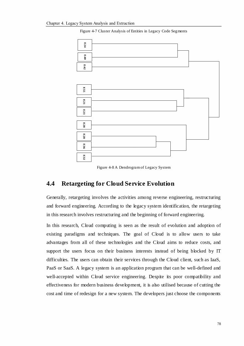
Chapter 4. Legacy System Analysis and Extraction
78
Figure 4-7 Cluster Analysis of Entities in Legacy Code Segments
E2
1E
23
E2
4E
40
E4
2E
55
E3
6E
32
E2
8E
28
Figure 4-8 A Dendrogram of Legacy System
4.4 Retargeting for Cloud Service Evolution
Generally, retargeting involves the activities among reverse engineering, restructuring
and forward engineering. According to the legacy system identification, the retargeting
in this research involves restructuring and the beginning of forward engineering.
In this research, Cloud computing is seen as the result of evolution and adoption of
existing paradigms and techniques. The goal of Cloud is to allow users to take
advantages from all of these technologies and the Cloud aims to reduce costs, and
support the users focus on their business interests instead of being blocked by IT
difficulties. The users can obtain their services through the Cloud client, such as IaaS,
PaaS or SaaS. A legacy system is an application program that can be well-defined and
well-accepted within Cloud service engineering. Despite its poor compatibility and
effectiveness for modern business development, it is also utilised because of cutting the
cost and time of redesign for a new system. The developers just choose the components
Chapter 4. Legacy System Analysis and Extraction
79
they require and reuse them to construct a new system.
The users‘ new requirements such as functional and non-functional requirements are
added on top of the software model (PIM) when the system is reengineering, and these
requirements are implemented by a number of program codes or architecture
restructuring. These resources can be obtained from the reuse components. Since those
requirements are handled at a specification level, this stage is seen as restructuring that
includes translation, abstraction, and transformation and so on.
Normally, reverse engineering is the main push of reengineering because it can resolve
a series of difficult problems, such as program understanding, identification and so on.
Forward engineering can always be completed with existing software development
techniques. Obviously, the proposed reengineering approach mainly focuses on
extracting useable components, restructuring them and integrating with requirements
and newly developed components. Finally, the evolution is retargeted in the Cloud
environment.
4.5 Summary
The analysis and extraction of a legacy system are very important before the Cloud
service oriented evolution. There are huge amounts of legacy software applications
which must be understood to decide whether they are suitable and valuable to evolve
and for reusable components to be extracted for Cloud service oriented application. In
order to assess and identify the useful components hidden in a legacy system, this
chapter proposed an assessment approach to decide the legacy system in a Cloud
environment and adopt the techniques of program slicing with improved algorithm and
software clustering for analysing and capturing legacy components. Although those
techniques are not very new, the improved activities support ensures the proposed
process efficiently. The contents covered in this chapter are concluded as follows:
Firstly, analyse the problem for the assessment and propose a legacy system
assessment approach based on AHP with three aspects including application,
internal environment and external environment. The assessment framework
combines the features of Cloud categories to judge whether and which types of
Chapter 4. Legacy System Analysis and Extraction
80
legacy systems are suitable to evolve into Cloud services. The whole process is
very important for the proposed approach because it is the judgement stages that
can help the developers select the legacy systems.
Secondly, combine the static and dynamic program slicing techniques to
decompose a program as an initial step for the evolution of legacy systems. An
improved slicing algorithm is proposed to analyse the legacy code. The PDG
analysis is used to represent program and slicing processes.
Thirdly, software clustering techniques are adopted to acquire the corresponding
legacy code segments. The agglomerative hierarchical clustering method is used to
extract the independent components. The hierarchical structure is shown by a
dendrogram. The architect‘s view and users‘ requirements help to decide the cutting
point in the dendrogram. Reverse engineering plays a vital role in the process.
Fourthly, the retargeting process for Cloud service oriented evolution is introduced,
which is taken as a guide for the following evolution activities.
Chapter 5. Cloud Oriented Service Migration
81
Chapter 5 Cloud Oriented Service
Migration
Objectives
__________________________________________________________________
To present the evolution process into Cloud environment.
To describe the evolution process within Cloud environment.
__________________________________________________________________
5.1 Overview
In the literature review, there is little work that has been done on how to consider a
three-dimensional evolution through the matching relationship among software
functions, software qualities and software models. No suitable method or solution can
be adopted in this area. Meanwhile, no systematic research discusses the evolution into
and within computing environments together. Thus, two phases‘ evolution processes are
contributed in this Chapter. The defined rules for supporting the whole process are
utilised to implement the Cloud service purpose.
After the analysis and identification stage, the legacy code segments with reusable
information are sliced and captured, and they can be utilised to handle NFRs and
software functions. The following stage will complete the Cloud service implementation.
In this Chapter, the details of handling the relationships among software functions,
software qualities and software models will be described, which includes the
corresponding algorithms and rules.
5.2 Evolution Process into Cloud Environment
As seen in Figure 3-2, the first evolution phase can be described via the abstraction and
transferring process with certain features for Cloud services. Legacy systems are
analysed and PSM, functions and NFRs are extracted via reverse engineering in the
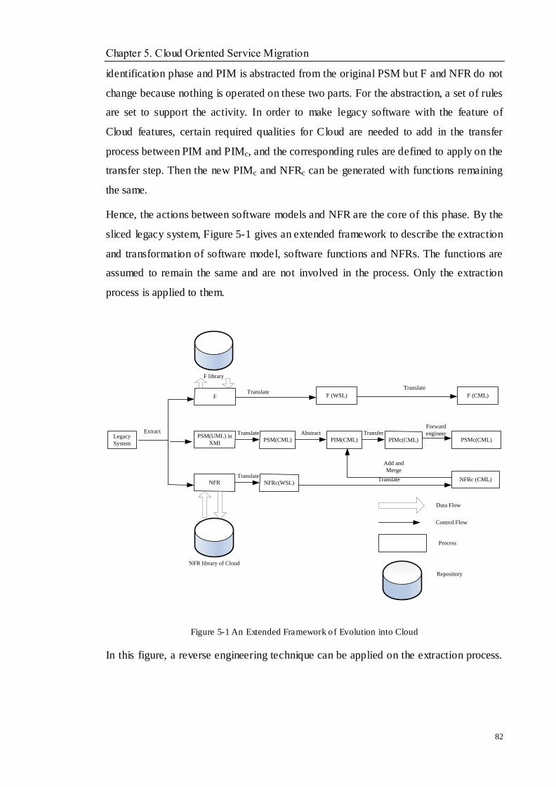
Chapter 5. Cloud Oriented Service Migration
82
identification phase and PIM is abstracted from the original PSM but F and NFR do not
change because nothing is operated on these two parts. For the abstraction, a set of rules
are set to support the activity. In order to make legacy software with the feature of
Cloud features, certain required qualities for Cloud are needed to add in the transfer
process between PIM and PIMc, and the corresponding rules are defined to apply on the
transfer step. Then the new PIMc and NFRc can be generated with functions remaining
the same.
Hence, the actions between software models and NFR are the core of this phase. By the
sliced legacy system, Figure 5-1 gives an extended framework to describe the extraction
and transformation of software model, software functions and NFRs. The functions are
assumed to remain the same and are not involved in the process. Only the extraction
process is applied to them.
Legacy
System
PSM(UML) in
XMI
F
NFR
PSM(CML)
NFRc(WSL)
PIM(CML) PIMc(CML) PSMc(CML)
NFRc (CML)
NFR library of Cloud
Data Flow
Control Flow
Process
Repository
Extract Translate Abstract
Add and
MergeTranslate
Transfer
Translate
Forward
engineer
F library
F (WSL)Translate
Translate
F (CML)
Figure 5-1 An Extended Framework of Evolution into Cloud
In this figure, a reverse engineering technique can be applied on the extraction process.
Chapter 5. Cloud Oriented Service Migration
83
There are three parts that need to be extracted for the proposed framework, namely, F
represents functions that show what the system can do, NFRs show how the system can
do it and a software model, and software models like PIM, PSM.
To extract functions, the design documents, user requirements and code for a software
system can be used to complete the process. In the sliced code, the functional content
can be obtained easily. Then the WSL representations of functions are translated from
the source code. The transformation rules are all based on the SERG (Software
Evolution Research Group in De Montfort University) work [138, 139, 140]. The
function library can be interacted with extracted functions in time. The obtained CML
(Common Modelling Language) [27] model can be translated into UML stored with an
XMI format.
In order to analyse and extract NFRs of a legacy system, the ISO quality tree in Figure
2-3 is utilised as criteria to analyse the NFRs through design specifications and the
views of the stakeholders in the sliced code. First, take any of eight main qualities in the
ISO quality tree and compare with the information in the design specifications. A
detailed introduction will be given to be analysed in Section 5.2.2. Next, the same action
on functions is always applied on NFRs to obtained WSL representations of NFRs.
Meanwhile, a NFRs library of Cloud is added into the existing NFRs for making the
new system suitable in a Cloud environment. Finally, the NFRc (CML) is merged into
PIM to generate new a PIM with transformation rules. In order to exchange information,
XMI can also be used to store the new NFRc.
The PSM (UML) is extracted by the interconnection ship in the code, and it is stored in
XMI format. Then the translation is applied from PSM (UML) to PSM (CML) with the
same constructs. The following abstraction aims to acquire PIM (CML) to merge the
added NFRc. Finally, the new PSMc (CML) can be established by forward engineering
and stored in XMI format.
Before the introduction of each sub process, a few preparations are needed. As seen in
the figure, there are two languages including WSL (Wide Spectrum Language) [146]
and CML (Common Modelling language) that are used to complete the translation from
source code to WSL, WSL to CML and UML to CML. CML is the extension of WSL
Chapter 5. Cloud Oriented Service Migration
84
kernel language for model management and is included in the WSL Modelling language
(WML) based on SERG work, which has been proved to resolve the program
transformation and model transformation respectively. The WML offers adequate
modelling concepts for model transformation of OO and process-based programming.
MetaWML is proposed by Feng [27], which supports a model transformation, which is
the extension of MetaWSL [139] in SERG. Most constructs of CML are equivalent to
UML entities and its syntax for class, process, relationship and model management can
be obtained. The translation from WSL to CML is a process that transforms a program
into a model with corresponding rules. The PSM (CML) to PIM (CML) is the process
between model transformations with abstraction rules. All the final results are stored in
XMI format for the information exchange. Since CML‘s construct are equal to UML,
the implementation of CML storing in XMI is easy to conduct. The following
sub-sections introduce the details and relevant techniques, and the experiment in the
case study in Chapter 7 provides the proof.
5.2.1 WSL Representation
WSL contains all the operations needed for a programming and specification language
including Dijkstra‘s guarded commands [148]. The intention is to structure a language
that performs as an intermediate language while processing the legacy systems. It was
designed for reengineering tasks that cover the following characters:
1. Simple, regular and formal semantics.
2. Clear and simple syntax.
3. A wide series of transformations with correctness conditions.
4. The ability to express low-level and high- level programs.
The WSL is built up in a series of layers from a small mathematically tractable WSL
kernel language that can be extended by adding new constructs. This kernel language
consists of the following primitive and compound statements:
Assertion {P} – If the formula P is true, the statement terminates; otherwise, it
aborts or never ends.
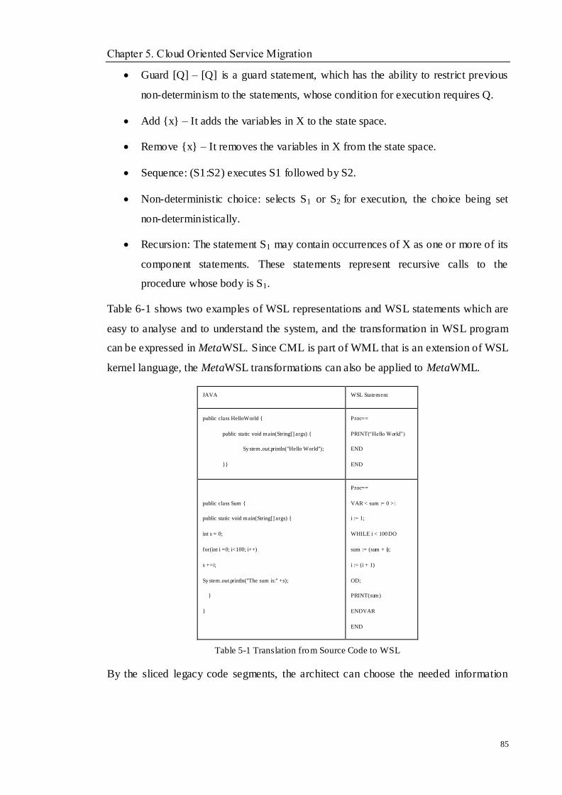
Chapter 5. Cloud Oriented Service Migration
85
Guard [Q] – [Q] is a guard statement, which has the ability to restrict previous
non-determinism to the statements, whose condition for execution requires Q.
Add {x} – It adds the variables in X to the state space.
Remove {x} – It removes the variables in X from the state space.
Sequence: (S1:S2) executes S1 followed by S2.
Non-deterministic choice: selects S1 or S2 for execution, the choice being set
non-deterministically.
Recursion: The statement S1 may contain occurrences of X as one or more of its
component statements. These statements represent recursive calls to the
procedure whose body is S1.
Table 6-1 shows two examples of WSL representations and WSL statements which are
easy to analyse and to understand the system, and the transformation in WSL program
can be expressed in MetaWSL. Since CML is part of WML that is an extension of WSL
kernel language, the MetaWSL transformations can also be applied to MetaWML.
JAVA WSL Statement
public class HelloWorld {
public static void main(String[] args) {
System.out.println("Hello World");
}}
Proc==
PRINT(―Hello World‖)
END
END
public class Sum {
public static void main(String[] args) {
int s = 0;
for(int i =0; i<100; i++)
s +=i;
System.out.println("The sum is:" +s);
}
}
Proc==
VAR < sum := 0 >:
i := 1;
WHILE i < 100 DO
sum := (sum + i);
i := (i + 1)
OD;
PRINT(sum)
ENDVAR
END
Table 5-1 Translation from Source Code to WSL
By the sliced legacy code segments, the architect can choose the needed information
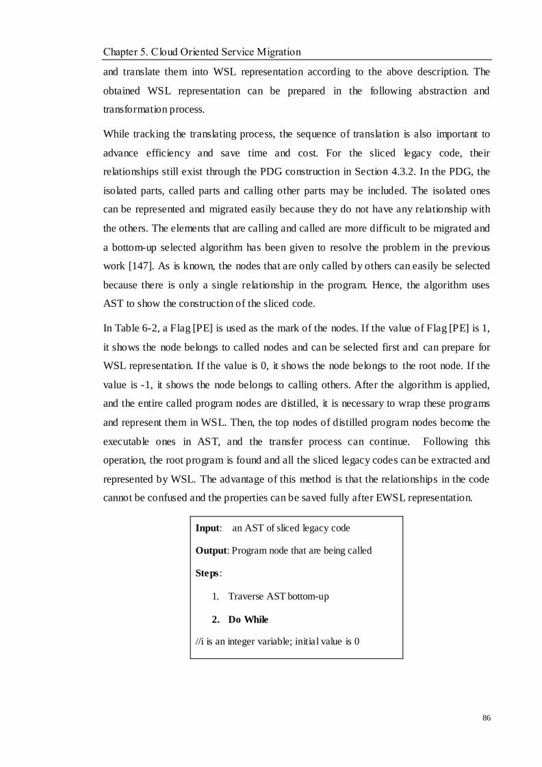
Chapter 5. Cloud Oriented Service Migration
86
and translate them into WSL representation according to the above description. The
obtained WSL representation can be prepared in the following abstraction and
transformation process.
While tracking the translating process, the sequence of translation is also important to
advance efficiency and save time and cost. For the sliced legacy code, their
relationships still exist through the PDG construction in Section 4.3.2. In the PDG, the
isolated parts, called parts and calling other parts may be included. The isolated ones
can be represented and migrated easily because they do not have any relationship with
the others. The elements that are calling and called are more difficult to be migrated and
a bottom-up selected algorithm has been given to resolve the problem in the previous
work [147]. As is known, the nodes that are only called by others can easily be selected
because there is only a single relationship in the program. Hence, the algorithm uses
AST to show the construction of the sliced code.
In Table 6-2, a Flag [PE] is used as the mark of the nodes. If the value of Flag [PE] is 1,
it shows the node belongs to called nodes and can be selected first and can prepare for
WSL representation. If the value is 0, it shows the node belongs to the root node. If the
value is -1, it shows the node belongs to calling others. After the algorithm is applied,
and the entire called program nodes are distilled, it is necessary to wrap these programs
and represent them in WSL. Then, the top nodes of distilled program nodes become the
executable ones in AST, and the transfer process can continue. Following this
operation, the root program is found and all the sliced legacy codes can be extracted and
represented by WSL. The advantage of this method is that the relationships in the code
cannot be confused and the properties can be saved fully after EWSL representation.
Input: an AST of sliced legacy code
Output: Program node that are being called
Steps:
1. Traverse AST bottom-up
2. Do While
//i is an integer variable; initial value is 0
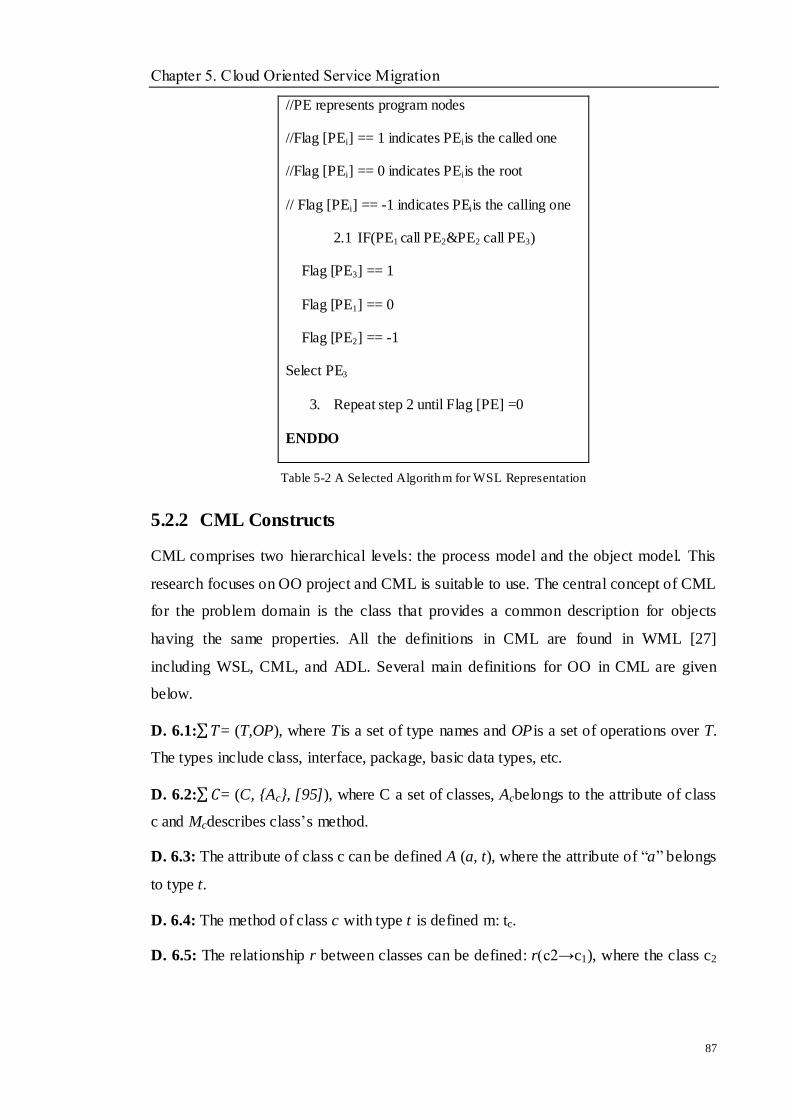
Chapter 5. Cloud Oriented Service Migration
87
//PE represents program nodes
//Flag [PEi] == 1 indicates PEiis the called one
//Flag [PEi] == 0 indicates PEiis the root
// Flag [PEi] == -1 indicates PEiis the calling one
2.1 IF(PE1 call PE2&PE2 call PE3)
Flag [PE3] == 1
Flag [PE1] == 0
Flag [PE2] == -1
Select PE3
3. Repeat step 2 until Flag [PE] =0
ENDDO
Table 5-2 A Selected Algorithm for WSL Representation
5.2.2 CML Constructs
CML comprises two hierarchical levels: the process model and the object model. This
research focuses on OO project and CML is suitable to use. The central concept of CML
for the problem domain is the class that provides a common description for objects
having the same properties. All the definitions in CML are found in WML [27]
including WSL, CML, and ADL. Several main definitions for OO in CML are given
below.
D. 6.1: 𝑇= (T,OP), where Tis a set of type names and OPis a set of operations over T.
The types include class, interface, package, basic data types, etc.
D. 6.2: 𝐶= (C, {Ac}, [95]), where C a set of classes, Acbelongs to the attribute of class
c and Mcdescribes class‘s method.
D. 6.3: The attribute of class c can be defined A (a, t), where the attribute of ―a‖ belongs
to type t.
D. 6.4: The method of class c with type t is defined m: tc.
D. 6.5: The relationship r between classes can be defined: r(c2→c1), where the class c2
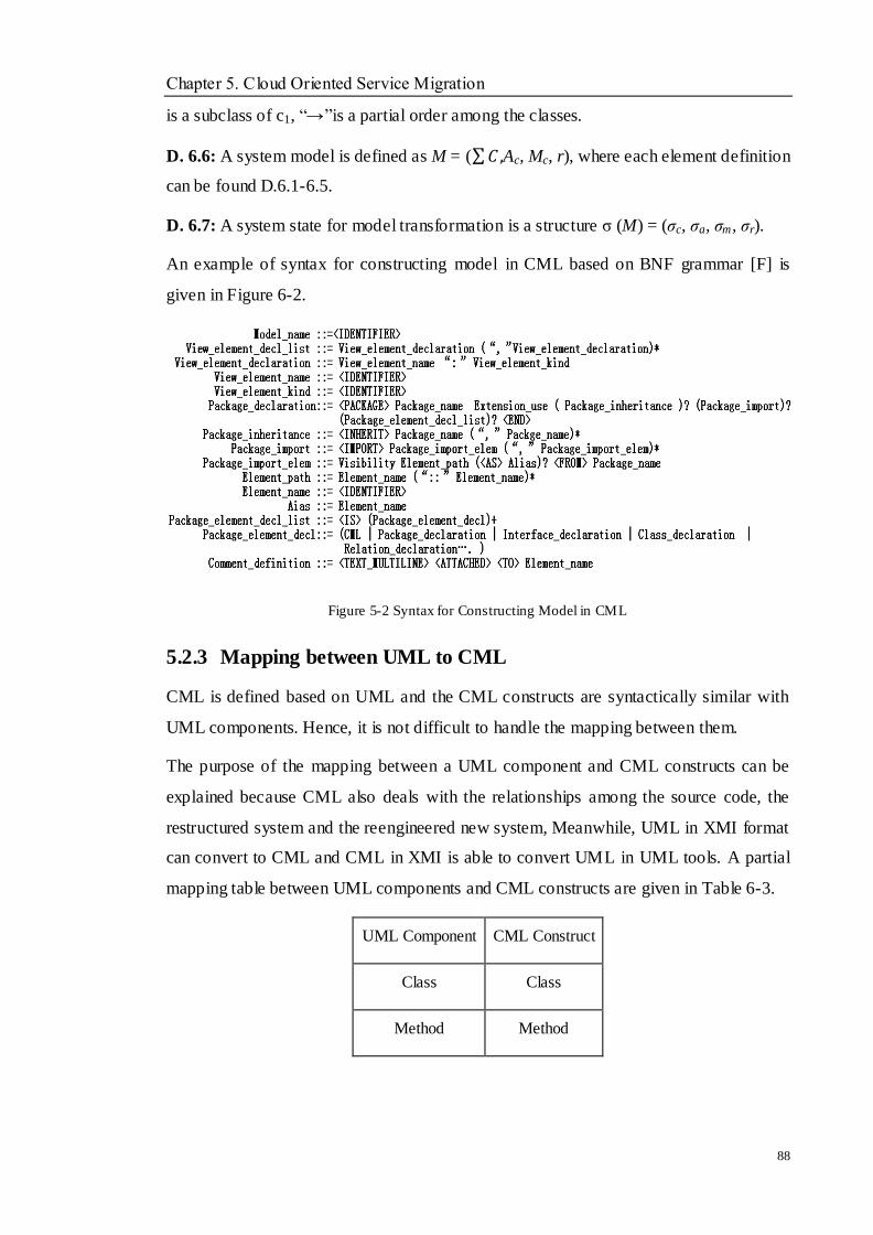
Chapter 5. Cloud Oriented Service Migration
88
is a subclass of c1, ―→‖is a partial order among the classes.
D. 6.6: A system model is defined as M = ( 𝐶 ,Ac, Mc, r), where each element definition
can be found D.6.1-6.5.
D. 6.7: A system state for model transformation is a structure σ (M) = (σc, σa, σm, σr).
An example of syntax for constructing model in CML based on BNF grammar [F] is
given in Figure 6-2.
Figure 5-2 Syntax for Constructing Model in CML
5.2.3 Mapping between UML to CML
CML is defined based on UML and the CML constructs are syntactically similar with
UML components. Hence, it is not difficult to handle the mapping between them.
The purpose of the mapping between a UML component and CML constructs can be
explained because CML also deals with the relationships among the source code, the
restructured system and the reengineered new system, Meanwhile, UML in XMI format
can convert to CML and CML in XMI is able to convert UML in UML tools. A partial
mapping table between UML components and CML constructs are given in Table 6-3.
UML Component CML Construct
Class Class
Method Method

Chapter 5. Cloud Oriented Service Migration
89
Attribute Attribute
Package Package
Interface Class
Object Instance
Association Relationship
Activity Activity
Message Message
Comment Comment
Sequence Collaboration
Table 5-3 A Partial Mapping between UML Component and CML Construct
5.2.4 Transformation from WSL to CML
The CML model is an OO model and WSL is a representation of a source code of a
legacy system. In order to obtain CML model from EWSL code, the object class
identification needs to be implementation. A CML construction method is proposed to
perfect the current work in SERG research.
For the transformation, the key point is to identify possible object classes in the WSL
code and restructure the variables and procedures in CML.
To facilitate the transformation, an improved transformation method based on [27] is
given to extract the corresponding information from the WSL code and adding them
into the CML object class. Compared to Feng‘s [27] method, this method gives a
computation of the common variables and procedures in a WSL code of legacy system,
which can be more correct when generating the class in CML. The algorithm is similar
with the proposed one in Chapter 4.3.3, but a few differences.
The steps of the extracting method are proposed as follows:
1. Define the Class name in CML model by the functions description in WSL.
Chapter 5. Cloud Oriented Service Migration
90
2. Construct the data matrix for all the variables and procedures of WSL code
respectively. Let ―1 to 1‖ denote two variables or two procedures which have
common data dependency or interaction, which means that the two variables
should probably be assigned to the same class in CML, or that the two
procedures should probably be assigned to the same class in CML, ―0 to 0‖ for
no relationships means that they should probably be assigned in different classes,
―1 to 0‖and ―0 to 1‖ denote the single interaction between the procedures, which
mean the two procedures should probably be assigned in two classes.
3. Generate a cluster through merging two variables or two procedures with ―1 to 1‖
match.
4. Obtain the new data matrix for a new cluster by taking OR operations on the
vector.
5. Update the similarities to decide whether other variables or procedures can be
assigned to the same class like the acquired cluster.
6. Repeat 3, 4and 5 until no variables or procedures are left.
7. Complete the transformation and add the merged variables or procedures in
CML model in XMI format.
5.2.5 Extraction and Translation for Software Functions
From their introduction in literature, software functions mean what a system can do, and
they will be found in design documents, user requirements and the source code. This
research assumes the legacy systems do not lack these documents. The ―verb-object‖
pair‘s generation in the documents can be regarded as the functional contents
description. For the selected HRM system by Java in the document, ―A HRM includes
department management, employee management…..‖ Then the pairs can be divided into
―HRM includes‖, ―department management‖ and ―employee management‖, and find the
corresponding code information in the PDG. As discussed in Chapter 4, the divided
pairs can be used as the cutting point to finally extract the function components. The
matching process between the pairs and the PDG of the system is completed by the
following proposed mapping rules in Table 5-3. Chapter 7 will give the process in a

Chapter 5. Cloud Oriented Service Migration
91
case study.
)property.p),method.cattribute.c((get)Package(Classe)p(c
truevisibility.oobjectsO{)Verb,Object(r
)property.m(getMethodsM
truevisibility.vverbsV{)Object,Verb(r
)property).p(c(get)Package(Class)p(C
truevisibility.oobjectsO{)Object,bjectO(r
After the extraction of the code of functions, WSL representation is used to translate the
source code, and CML is obtained by WSL and the UML information which can be
stored in XMI format.
5.2.6 NFR Extraction and NFRc Generation Process
In order to make a legacy system with Cloud features, the new NFR for Cloud should be
collected and stored in NFRc library documents. By the concluded criteria for Cloud
attributes of each Cloud category in Figure 5.2, the NFRc library is easy to build and
able to guide what requirements need to be added in the existing system. Generally
speaking, most of NFRs standard in the ISO tree are equal to the Cloud attributes. The
NFRc library can supply the existing NFRs through the new needs of users and external
environments.
The definition of each NFR can be found in the ISO standard, only several NFRs are
given here due to the space limitation of the thesis.
Portability: work for several platforms
Modifiability: addition of new functionalities
Testability: ease of testing and error reporting
Understandability: of design, architecture, code
Integrability: ability to integrate components
Next, by the design specification of a legacy system and source code, the NFRs can be
extracted through the design specification and ISO definition. An algorithm is given to
analyse and extract the NFRs from the legacy system. A tree structure is used to analyse
this, which includes ―+‖ (positive effect) and ―-‖ (negative effect) among the entities.
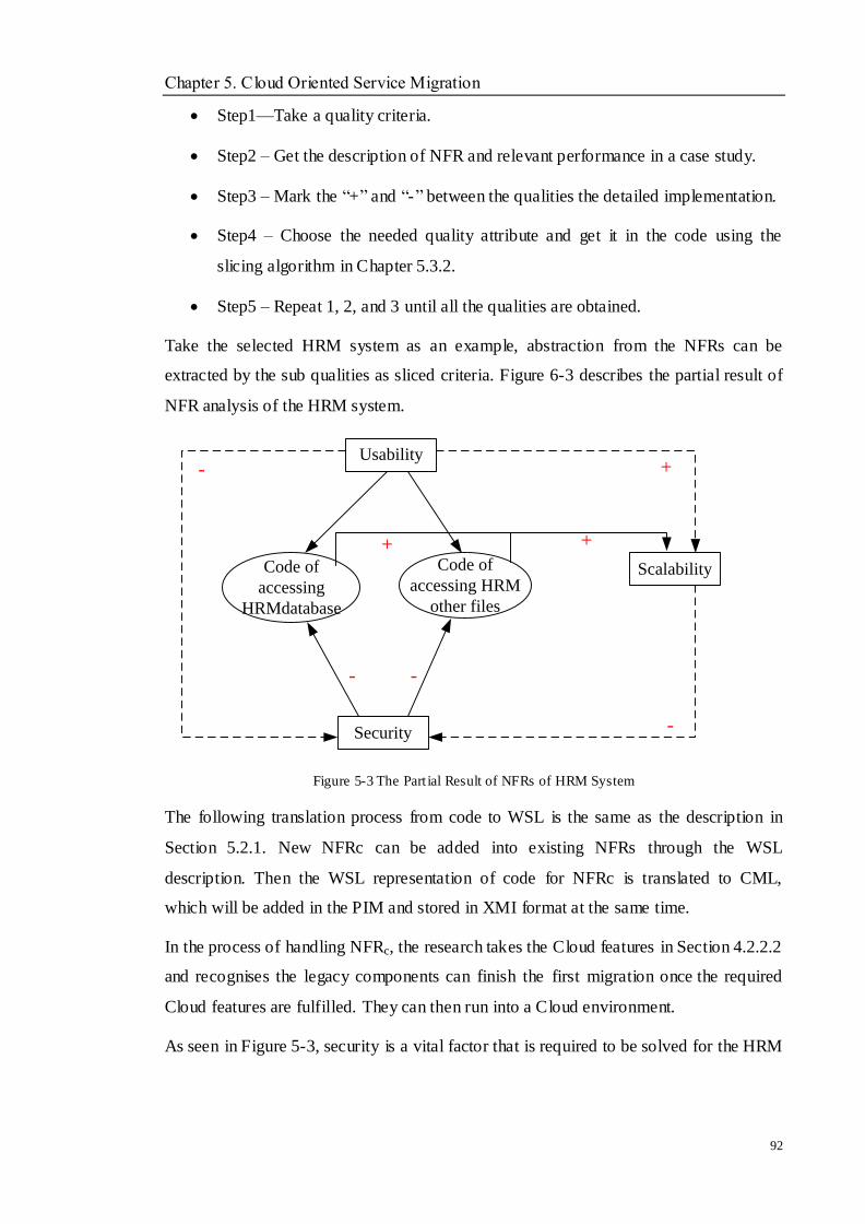
Chapter 5. Cloud Oriented Service Migration
92
Step1—Take a quality criteria.
Step2 – Get the description of NFR and relevant performance in a case study.
Step3 – Mark the ―+‖ and ―-‖ between the qualities the detailed implementation.
Step4 – Choose the needed quality attribute and get it in the code using the
slicing algorithm in Chapter 5.3.2.
Step5 – Repeat 1, 2, and 3 until all the qualities are obtained.
Take the selected HRM system as an example, abstraction from the NFRs can be
extracted by the sub qualities as sliced criteria. Figure 6-3 describes the partial result of
NFR analysis of the HRM system.
Usability
-
Code of
accessing
HRMdatabase
Code of
accessing HRM
other files
Security
-
-
Scalability
++
+
-
Figure 5-3 The Part ial Result of NFRs of HRM System
The following translation process from code to WSL is the same as the description in
Section 5.2.1. New NFRc can be added into existing NFRs through the WSL
description. Then the WSL representation of code for NFRc is translated to CML,
which will be added in the PIM and stored in XMI format at the same time.
In the process of handling NFRc, the research takes the Cloud features in Section 4.2.2.2
and recognises the legacy components can finish the first migration once the required
Cloud features are fulfilled. They can then run into a Cloud environment.
As seen in Figure 5-3, security is a vital factor that is required to be solved for the HRM
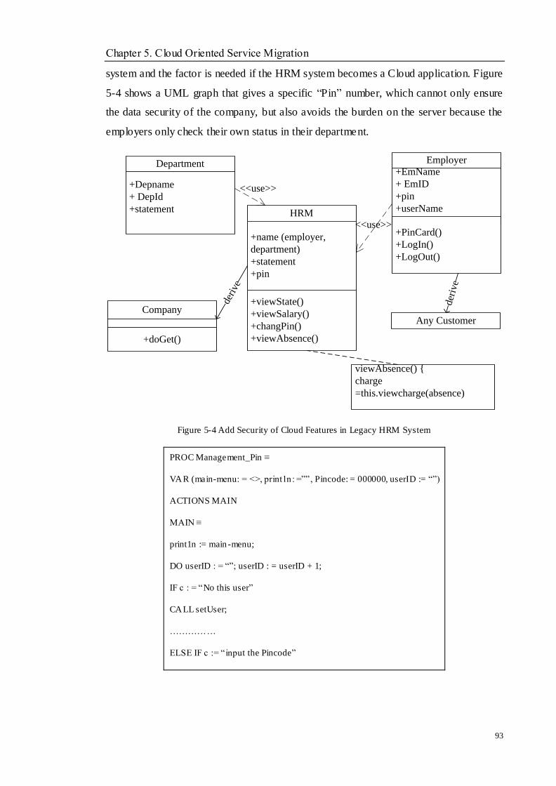
Chapter 5. Cloud Oriented Service Migration
93
system and the factor is needed if the HRM system becomes a Cloud application. Figure
5-4 shows a UML graph that gives a specific ―Pin‖ number, which cannot only ensure
the data security of the company, but also avoids the burden on the server because the
employers only check their own status in their department.
Company
+doGet()
HRM
+name (employer,
department)
+statement
+pin
+viewState()
+viewSalary()
+changPin()
+viewAbsence()
deri
ve
Employer
+EmName
+ EmID
+pin
+userName
+PinCard()
+LogIn()
+LogOut()
viewAbsence() {
charge
=this.viewcharge(absence)
<<use>>
Department
+Depname
+ DepId
+statement
<<use>>
Any Customer
der
ive
Figure 5-4 Add Security of Cloud Features in Legacy HRM System
PROC Management_Pin ≡
VAR (main-menu: = <>, print1n : =‖‖, Pincode: = 000000, userID := ―‖)
ACTIONS MAIN
MAIN ≡
print1n := main -menu;
DO userID : = ―‖; userID : = userID + 1;
IF c : = ―No this user‖
CALL setUser;
……………
ELSE IF c := ―input the Pincode‖

Chapter 5. Cloud Oriented Service Migration
94
CALL v iewUser;
IF c :=‖showUser‖
CALL showUser
……………….
FI………FI;
pirint1n : = main -menu OD
setUser ≡
print1n : = ― ‖;
if condit ion 1
THEN prinl1n := ―‖ + userID FI;
…………
viewUser ≡
print1n : = ―‖;
if condit ion 2
THEN print1n : = ―‖ + EmpID FI;
showUser≡
print1n : = ―‖;
if condit ion 2
THEN print1n : = ―‖ + EmpID + DepID FI;
…………
ENDACTIONS END
Table 5-4 WSL Translation of Management ―Pin‖
5.2.7 Model Transformation from PSM to PIM
When a PSM is extracted from a legacy system, a PSM can be mapped to a PIM with a
level of great enough abstraction. The transformation aims to shift from a detailed
description of the system to a functional representation of the system. Abstraction is a
process that transforms lower- level elements into higher- level elements, which can
reduce most details on a larger granularity. Without handling the abstractions correctly,
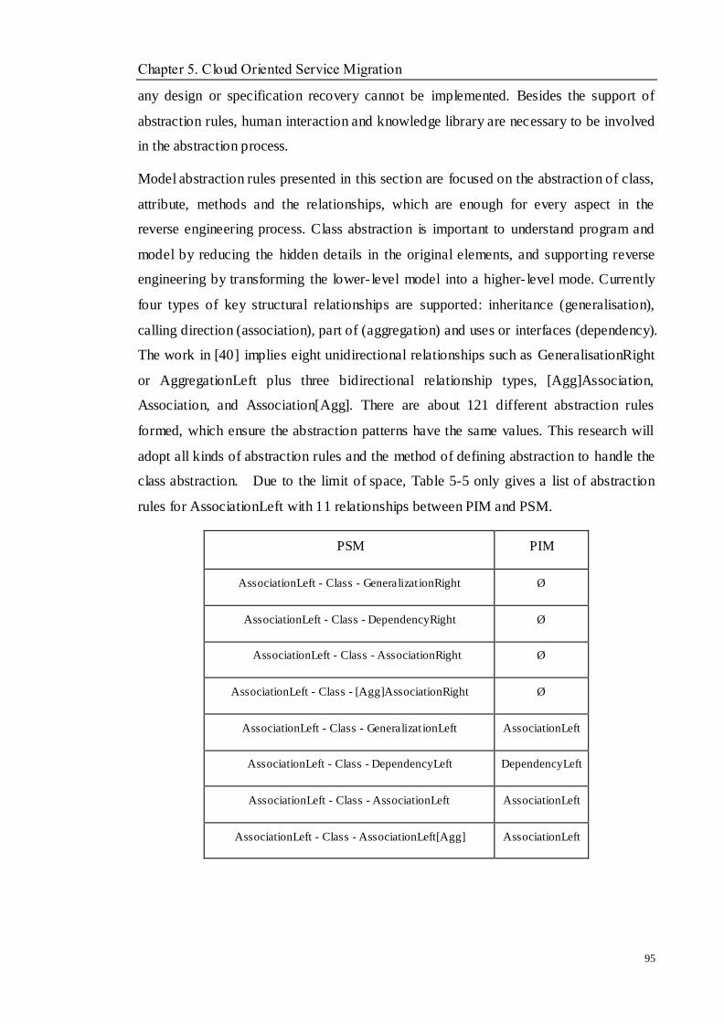
Chapter 5. Cloud Oriented Service Migration
95
any design or specification recovery cannot be implemented. Besides the support of
abstraction rules, human interaction and knowledge library are necessary to be involved
in the abstraction process.
Model abstraction rules presented in this section are focused on the abstraction of class,
attribute, methods and the relationships, which are enough for every aspect in the
reverse engineering process. Class abstraction is important to understand program and
model by reducing the hidden details in the original elements, and supporting reverse
engineering by transforming the lower- level model into a higher- level mode. Currently
four types of key structural relationships are supported: inheritance (generalisation),
calling direction (association), part of (aggregation) and uses or interfaces (dependency).
The work in [40] implies eight unidirectional relationships such as GeneralisationRight
or AggregationLeft plus three bidirectional relationship types, [Agg]Association,
Association, and Association[Agg]. There are about 121 different abstraction rules
formed, which ensure the abstraction patterns have the same values. This research will
adopt all kinds of abstraction rules and the method of defining abstraction to handle the
class abstraction. Due to the limit of space, Table 5-5 only gives a list of abstraction
rules for AssociationLeft with 11 relationships between PIM and PSM.
PSM PIM
AssociationLeft - Class - Generalizat ionRight Ø
AssociationLeft - Class - DependencyRight Ø
AssociationLeft - Class - AssociationRight Ø
AssociationLeft - Class - [Agg]AssociationRight Ø
AssociationLeft - Class - Generalizat ionLeft AssociationLeft
AssociationLeft - Class - DependencyLeft DependencyLeft
AssociationLeft - Class - AssociationLeft AssociationLeft
AssociationLeft - Class - AssociationLeft[Agg] AssociationLeft
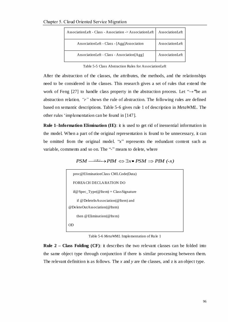
Chapter 5. Cloud Oriented Service Migration
96
AssociationLeft - Class - Association -> AssociationLeft AssociationLeft
AssociationLeft - Class - [Agg]Association AssociationLeft
AssociationLeft - Class - Association[Agg] AssociationLeft
Table 5-5 Class Abstraction Rules for AssociationLeft
After the abstraction of the classes, the attributes, the methods, and the relationships
need to be considered in the classes. This research gives a set of rules that extend the
work of Feng [27] to handle class property in the abstraction process. Let ―→”be an
abstraction relation, “r” shows the rule of abstraction. The following rules are defined
based on semantic descriptions. Table 5-6 gives rule 1 of description in MetaWML. The
other rules ‗implementation can be found in [147].
Rule 1–Information Elimination (IE): it is used to get rid of inessential information in
the model. When a part of the original representation is found to be unnecessary, it can
be omitted from the original model. ―x‖ represents the redundant content such as
variable, comments and so on. The ―-‖ means to delete, where
(-x) PIMPSMxPIMPSM )IE(r
proc@EliminationClass CMLCode(Data)
FOREACH DECLARATION DO
if@Spec_Type(@Item) = ClassSignature
if @DeleteInAssociation(@Item) and
@DeleteOutAssociation(@Item)
then @Eliminat ion(@Item)
OD
Table 5-6 MetaWML Implementation of Rule 1
Rule 2 – Class Folding (CF): it describes the two relevant classes can be folded into
the same object type through conjunction if there is similar processing between them.
The relevant definition is as follows. The x and y are the classes, and z is an object type.

Chapter 5. Cloud Oriented Service Migration
97
)zyx(PIM)y;x(PSM r )CF(
Rule 3 – Transitive Attribute (TA): it is used to denote an abstraction rule that can
transitive the attributes among the same classes between PIM and PSM.
)x(PIM)x(PSMr )TA(
Rule 4 – Composition (C): it is used to combine the attributes or methods into a
generalised attribute or method when they have direct relationships, such as similarly
functions. The ―a‖ shows attribute, ―m‖ shows method.
3a2a1a,3M2M1M))3a(3M(PIM))2a(2M),1a(1M(PSMr )c(
By the defined abstraction rules, the model transformation language is needed to
conduct them. The MetaWML can define all the required aspects of model
transformation with model and meta-model abilities for WML including CML, WSL,
and ADL. A brief description of MetaWML is given to provide a clear understanding.
Since MetaWML is the extension of MetaWSL, they have the same naming convention
by the following rules:
All MetaWML functions begin with the symbol ―@‖.
The first letter of the name of function or procedure begins with a capital letter.
The underline character separates the name.
All the Boolean function names have an ending in ―?‖.
MetaWML provides a set of actions for expressing the behaviour, including
@Add_Class, @Remove_Class, @Extract_Class, @Add_Method, @Remove_Method,
@Move_Method, @Extract_Method, @PullUp_Method, @Creat_Instance,
@Destroy_Instance, @Destroy_Link and so on.
For manipulating the model elements, MetaWML has defined the query facilities that
could specify the requests on models. The query facilities are constructed by AST,
which are implemented as MetaWML functions. The query facilities of MetaWML have
two layers, one of which is a basic layer, which includes classes and methods by CML.

Chapter 5. Cloud Oriented Service Migration
98
For example, @Class_Query (Class c) asks whether the class c is indeed a class. Other
functions can be found in [27]. An example shows a procedure that absorbs all
association classes and abstracts the complex structures into a bigger picture in Table
5-7.The FOREACH construct is used to iterate over all the components of the current
selected item which satisfy the conditions. The example shows the MetaWML could
write a transformation in a few lines of code with most details.
proc@AbsorbAssociationClass CMLCode(Data)
FOREACH DECLARATION DO
if@Spec_Type(@Item) = ClassSignature
if @ExsitInAssociation(@Item) and @ExsitOutAssociation(@Item)
then @Absorb(@Item)
OD
Table 5-7 A Procedure Using Abstraction Rules in MetaWML
The other layer is an architectural layer that adds a series of functions to support
architectural notations through design patterns without writing the query code, such as
@CompositePattern (Class c1, c2) with the description whether the CompositePattern
relationship is held for class c1 and c2. In order to satisfy the implementation in Section
5.3, the query facilities are improved to add the architecture styles to conduct the
architecture refactoring in Section 5.3. Since the transformation among architecture
style is still currently an initial stage in MetaWML the styles of Client-Server and Peer
to Peer have been chosen to investigate.
Table 5-8 illustrates the Query facilities in an architectural layer of WML with the styles
of Client-Server and Peer-Peer, in which the relationship between two classes is used in
6 different ways. The connector and configuration can be implemented by the actions of
method and link.
Query Facilities Return
Types Descriptions
@ClientServer(Peer2Peer) Name List Return all the classes in ClientServer (Peer2Peer)style into a name
list
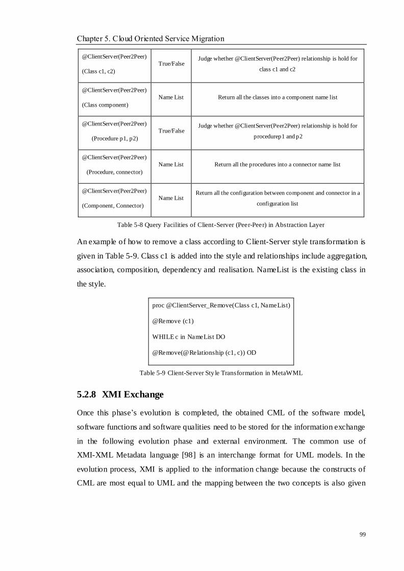
Chapter 5. Cloud Oriented Service Migration
99
@ClientServer(Peer2Peer)
(Class c1, c2)
True/False Judge whether @ClientServer(Peer2Peer) relationship is hold for
class c1 and c2
@ClientServer(Peer2Peer)
(Class component)
Name List Return all the classes into a component name list
@ClientServer(Peer2Peer)
(Procedure p1, p2)
True/False Judge whether @ClientServer(Peer2Peer) relationship is hold for
procedurep1 and p2
@ClientServer(Peer2Peer)
(Procedure, connector)
Name List Return all the procedures into a connector name list
@ClientServer(Peer2Peer)
(Component, Connector)
Name List Return all the configuration between component and connector in a
configuration list
Table 5-8 Query Facilities of Client-Server (Peer-Peer) in Abstraction Layer
An example of how to remove a class according to Client-Server style transformation is
given in Table 5-9. Class c1 is added into the style and relationships include aggregation,
association, composition, dependency and realisation. NameList is the existing class in
the style.
proc @ClientServer_Remove(Class c1, NameList)
@Remove (c1)
WHILE c in NameList DO
@Remove(@Relationship (c1, c)) OD
Table 5-9 Client-Server Sty le Transformation in MetaWML
5.2.8 XMI Exchange
Once this phase‘s evolution is completed, the obtained CML of the software model,
software functions and software qualities need to be stored for the information exchange
in the following evolution phase and external environment. The common use of
XMI-XML Metadata language [98] is an interchange format for UML models. In the
evolution process, XMI is applied to the information change because the constructs of
CML are most equal to UML and the mapping between the two concepts is also given
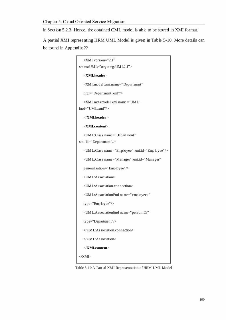
Chapter 5. Cloud Oriented Service Migration
100
in Section 5.2.3. Hence, the obtained CML model is able to be stored in XMI format.
A partial XMI representing HRM UML Model is given in Table 5-10. More details can
be found in Appendix ??
<XMI version=‖2.1‖
xmlns:UML=‖org.omg/UML2.1‖>
<XMI.header>
<XMI.model xmi.name=‖Department‖
href=‖Department.xml‖/>
<XMI.metamodel xmi.name=‖UML‖
href=‖UML.xml‖/>
</XMI.header>
<XMI.content>
<UML:Class name=‖Department‖
xmi.id=‖Department‖/>
<UML:Class name="Employee" xmi.id="Employee"/>
<UML:Class name="Manager" xmi.id="Manager‖
generalization=" Employee"/>
<UML:Association>
<UML:Association.connection>
<UML:AssociationEnd name="employees"
type="Employee"/>
<UML:AssociationEnd name="personrOf"
type="Department"/>
</UML:Association.connection>
</UML:Association>
</XMI.content>
</XMI>
Table 5-10 A Part ial XMI Representation of HRM UML Model
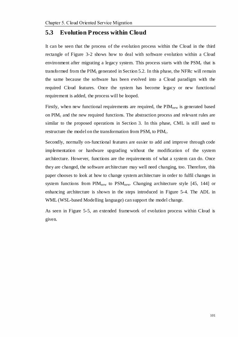
Chapter 5. Cloud Oriented Service Migration
101
5.3 Evolution Process within Cloud
It can be seen that the process of the evolution process within the Cloud in the third
rectangle of Figure 3-2 shows how to deal with software evolution within a Cloud
environment after migrating a legacy system. This process starts with the PSMc that is
transformed from the PIMc generated in Section 5.2. In this phase, the NFRc will remain
the same because the software has been evolved into a Cloud paradigm with the
required Cloud features. Once the system has become legacy or new functional
requirement is added, the process will be looped.
Firstly, when new functional requirements are required, the PIMnew is generated based
on PIMc and the new required functions. The abstraction process and relevant rules are
similar to the proposed operations in Section 3. In this phase, CML is still used to
restructure the model on the transformation from PSMc to PIMc.
Secondly, normally on-functional features are easier to add and improve through code
implementation or hardware upgrading without the modification of the system
architecture. However, functions are the requirements of what a system can do. Once
they are changed, the software architecture may well need changing, too. Therefore, this
paper chooses to look at how to change system architecture in order to fulfil changes in
system functions from PIMnew to PSMnew. Changing architecture style [45, 144] or
enhancing architecture is shown in the steps introduced in Figure 5-4. The ADL in
WML (WSL-based Modelling language) can support the model change.
As seen in Figure 5-5, an extended framework of evolution process within Cloud is
given.
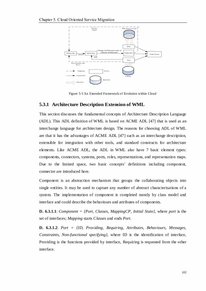
Chapter 5. Cloud Oriented Service Migration
102
PIMc(CML)
Fnew
NFRc
PSM(CML)
NFR library of Cloud
Data Flow
Control Flow
Process
Repository
F library
PSMc(CML)Abstract
Change Architecture style or
refactor architecture
Add
Become
Legacy
New Evolution with
New F
Target System
Triggering
Figure 5-5 An Extended Framework of Evolution within Cloud
5.3.1 Architecture Description Extension of WML
This section discusses the fundamental concepts of Architecture Description Language
(ADL). This ADL definition of WML is based on ACME ADL [47] that is used as an
interchange language for architecture design. The reasons for choosing ADL of WML
are that it has the advantages of ACME ADL [47] such as an interchange description,
extensible for integration with other tools, and standard constructs for architecture
elements. Like ACME ADL, the ADL in WML also have 7 basic element types:
components, connectors, systems, ports, roles, representations, and representation maps.
Due to the limited space, two basic concepts‘ definitions including component,
connector are introduced here.
Component is an abstraction mechanism that groups the collaborating objects into
single entities. It may be used to capture any number of abstract characterisations of a
system. The implementation of component is completed mostly by class model and
interface and could describe the behaviours and attributes of components.
D. 6.3.1.1: Component = {Port, Classes, MappingCP, Initial State}, where port is the
set of interfaces; Mapping starts Classes and ends Port.
D. 6.3.1.2: Port = {ID, Providing, Requiring, Attributes, Behaviours, Messages,
Constraints, Non-functional specifying}, where ID is the identification of interface,
Providing is the functions provided by interface, Requiring is requested from the other
interface.
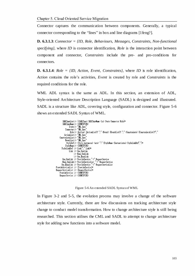
Chapter 5. Cloud Oriented Service Migration
103
Connector captures the communication between components. Generally, a typical
connector corresponding to the ―lines‖ in box and line diagrams [1feng?].
D. 6.3.1.3: Connector = {ID, Role, Behaviours, Messages, Constraints, Non-functional
specifying}, where ID is connector identification, Role is the interaction point between
component and connector, Constraints include the pre- and pro-conditions for
connectors.
D. 6.3.1.4: Role = {ID, Action, Event, Constraints}, where ID is role identification,
Action contains the role‘s activities, Event is created by role and Constraints is the
required conditions for the role.
WML ADL syntax is the same as ADL. In this section, an extension of ADL,
Style-oriented Architecture Description Language (SADL) is designed and illustrated.
SADL is a structure like ADL, covering style, configuration and connector. Figure 5-6
shows an extended SADL Syntax of WML.
Figure 5-6 An extended SADL Syntax of WML
In Figure 3-2 and 5-5, the evolution process may involve a change of the software
architecture style. Currently, there are few discussions on tracking architecture style
change to conduct model transformation. How to change architecture style is still being
researched. This section utilises the CML and SADL to attempt to change architecture
style for adding new functions into a software model.

Chapter 5. Cloud Oriented Service Migration
104
5.3.2 Refactoring Architecture for Model Transformation
As discussed above, while the new functions are needed and added into PIMnew CML
model, the PSMnew will be generated by PIMnew through a software architecture change.
Figure 5-7 presents a process of PSMnew generation.
PIMnew
Extract
Architecture Style
Design
Decide
Analyse
Yes
New Architecture Style
Forward Engineer
Target Architecture
PSMnew
No
Transform
Figure 5-7 A Process of PSMnew Generation
In the figure, the existing architecture style information can be extracted by the
connector and configuration of the SADL description with each architecture style
character. Then, the architecture style needed to judge whether it is suitable for adding
the functions. The relationships between architecture style types are given to assist the
decision. If changing the style, the transformation between the original and new style is
applied through the defined rules and new target architecture information is represented
by SADL. Finally, PSMnew is obtained by forward engineering with architecture rules.
5.3.2.1 Architecture Style Change
The extension SADL has been given to describe the architecture information in the
model. As the core concept in the extension, the architecture styles need to be
investigated first. Then the transformation rules are defined in SADL to implement the
architecture style change.
Architecture styles have been studied for a long time, the term ‗architectural pattern‘ as
a synonym for ‗style‘ has been used commonly. Thus, a style describes element and
relation types together with a set of constraints on how elements and relations are used
and interacted in architecture. Currently, there is not a clear classification for the
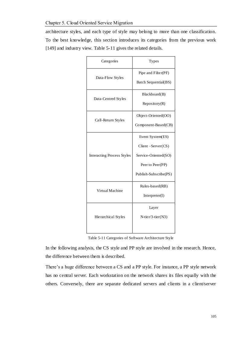
Chapter 5. Cloud Oriented Service Migration
105
architecture styles, and each type of style may belong to more than one classification.
To the best knowledge, this section introduces its categories from the previous work
[149] and industry view. Table 5-11 gives the related details.
Categories Types
Data-Flow Styles
Pipe and Filter(PF)
Batch Sequential(BS)
Data-Centred Styles
Blackboard(B)
Repository(R)
Call-Return Styles
Object-Oriented(OO)
Component-Based(CB)
Interacting Process Styles
Event System(ES)
Client –Server(CS)
Service-Oriented(SO)
Peer to Peer(PP)
Publish-Subscribe(PS)
Virtual Machine
Rules-based(RB)
Interpreter(I)
Hierarchical Styles
Layer
N-tier/3-tier(N3)
Table 5-11 Categories of Software Architecture Style
In the following analysis, the CS style and PP style are involved in the research. Hence,
the difference between them is described.
There‘s a huge difference between a CS and a PP style. For instance, a PP style network
has no central server. Each workstation on the network shares its files equally with the
others. Conversely, there are separate dedicated servers and clients in a client/server
Chapter 5. Cloud Oriented Service Migration
106
network. Through client workstations, users can access most files, which are generally
stored on the server. The server could determine which users can access the files on the
network. PP style is usually suitable for small business or home use because of the
limitation of space but almost no security. On the other hand, a CS style network can
become large but is also most expensive. Cloud computing could perform powerfully
for the CS style network. Servers can be put in the Cloud, which would provide the
resources you want.
While handling the change between architecture styles, the activities are mainly focused
on the alteration in the same category because the system architecture and original
functions will alter if the changes happen between different categories. This research
mainly discusses how to change a software architecture style with new required
functions and the process of implementing a new style of system with new functions
which is easy to conduct by using a software architecture tool, such as AGG. The
transformation process can be expressed by MetaSADL. Since SADL is an extension of
WML ADL while WML is an extension of WSL, the MetaWSL transformations are still
suitable for MetaADL.
A transformation space for architecture style is defined to be a 4-tuple (O, T, F, R),
where,
O is a set of initial architecture styles; T is a set of target architecture styles; F is a set of new requirements; and R is a set of the rules of transforming into target architecture styles.
The transformation process of styles can be seen as O T. A transformation
algorithm is presented in Table 5-12. The MetaSADL transformation process is with
same syntax of Table 5-9. A graph description is shown clearly in Figure 5-8.
F
R

Chapter 5. Cloud Oriented Service Migration
107
Transformation Algorithm:
Input: SADL Description of Model, New Functions and Styles
Output:SADL Description of New Style System with New Functions.
Steps:
1. Translate the new required functions into CML constructs. 2. Abstract the style information of existing model from SADL description.
3. Change the corresponding connector, configuration and component for the new style.
4. Translate the New Functions‘ CML constructs into SADL constructs, which mainly focus on
the management on classes and their implementation. MetaSADL can conduct the
transformation rules with the actions including @Add_Class, @Remove_Class, @Extract_Class, @Add_Method, @Remove_Method, @Move_Method,
@Extract_Method, @PullUp_Method, @Creat_Instance, @Destroy_Instance,
@Destroy_Link, @Package, @Group
5. Update SADL model.
Table 5-12 A Transformation Algorithm of Style Change
P1
P2 P3
L=
Server
Client1 Client2
R=Transformation algorithm
Figure 5-8 A Graph Description of Style Change
5.3.2.2 Mapping SADL into UML XMI
Once SADL model is updated, the new system‘s architecture can be redesigned with the
model information by the existing tool support. However, they first need to map into
UML XMI for the information exchange. This section gives the mapping rules from
SADL to UML XMI in Table 5-13 and Table 5-14 presents a small mapping example.
A case study will prove and give a detailed UML instance.
SADL UML XMI
Style Model
Component xmi:type =‖uml:Class‖
Connector xmi:type =‖uml:Class‖
Role Port [in][out]
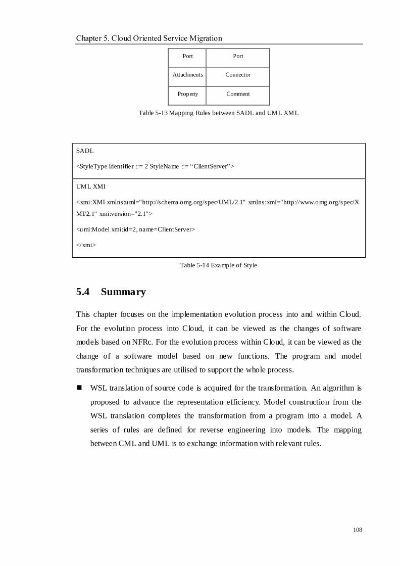
Chapter 5. Cloud Oriented Service Migration
108
Port Port
Attachments Connector
Property Comment
Table 5-13 Mapping Rules between SADL and UML XML
SADL
<StyleType identifier ::= 2 StyleName ::= ―ClientServer‖>
UML XMI
<xmi:XMI xmlns:uml="http://schema.omg.org/spec/UML/2.1" xmlns:xmi="http://www.omg.org/spec/X
MI/2.1" xmi:version="2.1">
<uml:Model xmi:id=2, name=ClientServer>
</xmi>
Table 5-14 Example of Style
5.4 Summary
This chapter focuses on the implementation evolution process into and within Cloud.
For the evolution process into Cloud, it can be viewed as the changes of software
models based on NFRc. For the evolution process within Cloud, it can be viewed as the
change of a software model based on new functions. The program and model
transformation techniques are utilised to support the whole process.
WSL translation of source code is acquired for the transformation. An algorithm is
proposed to advance the representation efficiency. Model construction from the
WSL translation completes the transformation from a program into a model. A
series of rules are defined for reverse engineering into models. The mapping
between CML and UML is to exchange information with relevant rules.
Chapter 5. Cloud Oriented Service Migration
109
The analysis of NFR and functions extraction is introduced. The ―verb-object‖ pairs
are utilised to obtain the existing functions and an algorithm for extracting NFRs
from a legacy system is proposed.
The abstraction technique is applied between the models, which is an effective way
to reduce the complex details of a software system. The process aims to add new
NFRs and functions to change an existing software model. A set of abstraction and
mapping rules are given to assist the process. XMI is used to store the final model
for information exchange.
The architecture refactoring is conducted from the change of architecture styles. A
transformation method based on the concluded styles is introduced. SADL is
illustrated as an extension of ADL with syntax. In order to store a SADL model, the
mapping rules between SADL and UML XMI are listed.
Chapter 6. Cloud Oriented Service Integration
110
Chapter 6 Cloud Oriented Service
Integration
Objectives
__________________________________________________________________
To design a Cloud service enabled integration architecture
To define appropriate middleware to integrate identified services to a heavily
heterogeneous Cloud service environment.
__________________________________________________________________
6.1 Overview
Cloud computing is a model for enabling ubiquitous, convenient, on-demand network
access to a shared pool of configurable computing resources including networks, servers,
storage and applications that can be rapidly provisioned and released with few
management effort [103] .Currently, three main service models are researched:
Software as a Service (SaaS). The capability provided to the consumer is to
use the provider‘s application running on a Cloud infrastructure. The
applications are accessible from client devices through a thin client interface,
such as a web browser, or a program interface. Few configurations are
required for consumers.
Platform as a Service (PaaS). The capability provided to the consumer is to
deploy onto the Cloud infrastructure or acquired applications created using
program languages, services, libraries and the tools supported by the provider.
The consumer has control over the deployed applications and possibly
configuration settings for the applications.
Infrastructure as a Service (IaaS). The capability provided to the consumer is
to provision processing, storage, networks and other fundamental computing
resources where the consumer is able to deploy and run software, which can
Chapter 6. Cloud Oriented Service Integration
111
include operating systems and other applications. The consumer still needs to
control the operating systems, storage and developed applications, and
possibly limited control of selecting networking components, such as
firewalls.
While the Cloud service is referred, the service model needs to be pointed out. Currently,
SaaS is much preferred for most consumers and small business because most of them do
not want more management for the configurations, but like to use the services at any
time. Hence, this research focuses on how to invoke the functionalities from the evolved
legacy application in Chapter ?? through the web service techniques that run on the
Cloud.
The Cloud service oriented reengineering could bring great benefits for both legacy
systems and Cloud services. It performs by reusing legacy system resources into the
Cloud service environment. Compared with designing a new application, the proposed
approach is less risky and massively reduces cost and time. After the process of
Cloud-oriented service migration, the evolved service is required to integrate and deploy
into the Cloud environment, which can interact with the outside world.
This chapter focuses on addressing the following issues:
Design a Cloud service enabled integration architecture that allows the
functionalities of legacy systems to interact with the existing Cloud service
easily.
Define appropriate middleware to integrate the identified functionalities to a
heavily heterogeneous Cloud service environment.
Before the discussion of the above issues, the concepts of web services and EBS
(Enterprise Business Bus) need to be expressed first which are involved in the solution
process.
6.2 Web Service
Web service is one of the most active and widely used. It is based on an interoperable
protocol called SOAP (Simple Object Access Protocol) [133] that provides an envelope
Chapter 6. Cloud Oriented Service Integration
112
which encapsulates XML data for exchanging through the web architecture. SOAP is an
XML based protocol that handles all communications between client to client, server to
server, server to client and application to application.
Web services are discoverable by the clients through searching the UDDI (Universal
Description Discovery and Integration) directories, which publishes the web services as
standard constructs like WSDL (Web Services Description Language). UDDI is a
specialist for web services registration, which describes the service provider and
publisher details. It is also built on XML and SOAP. A WSDL is a construct document,
which is merely an XML document describing the messaging format of the exposed
services. In most cases, WSDL documents are static and do not change very often.
Therefore, most programming languages generate proxies for the client from WSDL. If
the WSDL document changes from one version to another, the vendors need to keep old
bindings and just add new bindings. Hence, the older clients can continue to work.
SaaS services are deployed into the Cloud just as web services and can also be
implemented using web services. Hence, the web service techniques can still be applied
to the integration process of a Cloud service.
6.3 Enterprise Service Bus
In the early 2000s, the IT industry introduced a bus-architecture technology, ESB
(Enterprise Service Bus) [30]. It improved the central service registry mechanism in
SOA and provided a software infrastructure for SOA implementation in enterprise
applications. ESB is a message-based bus architecture that consists of a series of service
containers. Each service container includes an adapter module, mediation module,
message routing module and processing module, management module and security
module. Each module is responsible for specific tasks. Figure 6-1 shows the
components of ESB.
Adapter module. It acts as a service connector to connect software services and
systems. A service adapter uses the native transaction interfaces to transfer
messages between the service container and service.
Mediation module. It transforms the protocol, message format and message
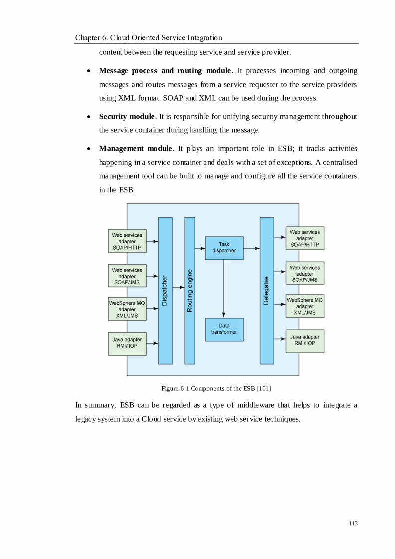
Chapter 6. Cloud Oriented Service Integration
113
content between the requesting service and service provider.
Message process and routing module . It processes incoming and outgoing
messages and routes messages from a service requester to the service providers
using XML format. SOAP and XML can be used during the process.
Security module. It is responsible for unifying security management throughout
the service container during handling the message.
Management module. It plays an important role in ESB; it tracks activities
happening in a service container and deals with a set of exceptions. A centralised
management tool can be built to manage and configure all the service containers
in the ESB.
Figure 6-1 Components of the ESB [101]
In summary, ESB can be regarded as a type of middleware that helps to integrate a
legacy system into a Cloud service by existing web service techniques.
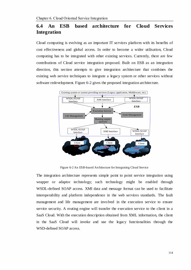
Chapter 6. Cloud Oriented Service Integration
114
6.4 An ESB based architecture for Cloud Services
Integration
Cloud computing is evolving as an important IT services platform with its benefits of
cost effectiveness and global access. In order to become a wider utilisation, Cloud
computing has to be integrated with other existing services. Currently, there are few
contributions of Cloud service integration proposed. Built on ESB as an integration
direction, this section attempts to give integration architecture that combines the
existing web service techniques to integrate a legacy system or other services without
software redevelopment. Figure 6-2 gives the proposed integration architecture.
SaaSSaaS
SaaS
Existing system or system providing services (Legacy application, Middleware, etc)
WSDL/SOAP
Interface
WSDL/SOAP
InterfaceXMI Interface
WSDL/SOAP
Interface XMI Interface WSDL/SOAP
Interface
Client Client Client
Execution Service
Routing engine
(HTTP)
ESB
Life ManagementFault Management
Figure 6-2 An ESB-based Architecture for Integrating Cloud Service
The integration architecture represents simple point to point service integration using
wrapper or adaptor technology; such technology might be enabled through
WSDL-defined SOAP access. XMI data and message format can be used to facilitate
interoperability and platform independence in the web services standards. The fault
management and life management are involved in the execution service to ensure
service security. A routing engine will transfer the execution service to the client in a
SaaS Cloud. With the execution description obtained from XML information, the client
in the SaaS Cloud will invoke and use the legacy functionalities through the
WSD-defined SOAP access.
Chapter 6. Cloud Oriented Service Integration
115
6.5 Cloud Specific Service
Cloud services have emerged by combining Cloud computing and Web services to
achieve a faultless information processing system across heterogeneous, distributed,
dynamic virtual organisations that the user can access from any location. To construct
Cloud services with legacy components is tedious work, it may include a switch
between many tools, such as command shells, file managers, editors, application
containers, build tools, etc.
Being dynamic and stateful is the most difference between Cloud services and Web
services. With the support of stateful resources, Cloud can remember what has been
done from one invocation to another. The term state may be unclear and can cover many
different aspects of a system, from the value stored in a specific database record to the
temperature of the disk drive during the seeking process. In this research, a Cloud
stateful resource is defined as resources which have the following features: a
well-defined lifecycle known by one or more service providers and a specific set of state
data, expressible like an XML document format. Stateful resources can be managed via
Cloud service regulation. Once a system possesses the primary mechanisms of system
adaptation and hiding complexity, it will show a series of attributes, such as
independence in the control and management of the resources inside the system and the
service provisions outside the system.
Following the analysis and representing legacy system components by extracting and
transforming useful legacy assets into a Cloud oriented XML components, the extracted
useful resources are able to be deployed in the Cloud environment as stateful resources
to create Cloud services. These stateful resources can be isolated and fashioned into
components that can be integrated in Cloud service oriented architectures. Previous
sections show the process of legacy resource extraction and Cloud-oriented migration.
To perform a cooperate Cloud service in this section, the components identification, and
migration approach have been applied on a HRM system. The system is decomposed,
and interested components are migrated. As a result, the concerned addition and
subtraction Cloud components are retrieved. The following sections will discuss the
generation of Cloud stateful services.
Chapter 6. Cloud Oriented Service Integration
116
6.6 Cloud Services Description and Implementation
A resource properties document collects resource property elements, associated with a
web service‘s WSDL 2.0 portType definition to provide the declaration of the exposed
resource properties of the Web Services Resource Framework (WS-Resource). It may
be used by a service requestor to form an XML based query on the WS Resource. The
resource property elements are almost identical to service data elements.
In WS Resource properties specification, it defines the type and values of those
components of a WS Resource‘s state that can be viewed and modified by service
requestors through a web service interface. This specification does not dictate the means
by which a service implements a resource properties document. A given service
implementation may be selected to realise its implementation of the resource properties
document as an XMI instance document that is stored in some XMI repository.
Being stateful is necessary in Cloud service and Cloud can remember what has been
done from one invocation to another by the stateful resources‘ support. In this thesis, the
extracted legacy resources are deployed as stateful resources to create the Cloud
services. The defined stateful resources will have a specific set of state data expressible
as an XML document. A few rules are defined to create the stateful resources:
1. The complex type defining the resource properties document must define child
elements only. Using xsd: sequence or xsd: all is applied to the child
aggregation.
2. The complex type defining the resource properties document must define a
sequence of one or more child elements, called resource property elements.
Using XML schema element reference defines the child elements.
3. The complex type defining the resource properties document allows open
element content – xsd: any.
Figure 6-3 gives an example of the stateful resource properties of the HRM system
which has been selected in this thesis. In this example, the HRM system has been
considered as a stateful resource. There are six resource property components, named
Department, Employee, Position, Salary, Attendance and Training, as its resource
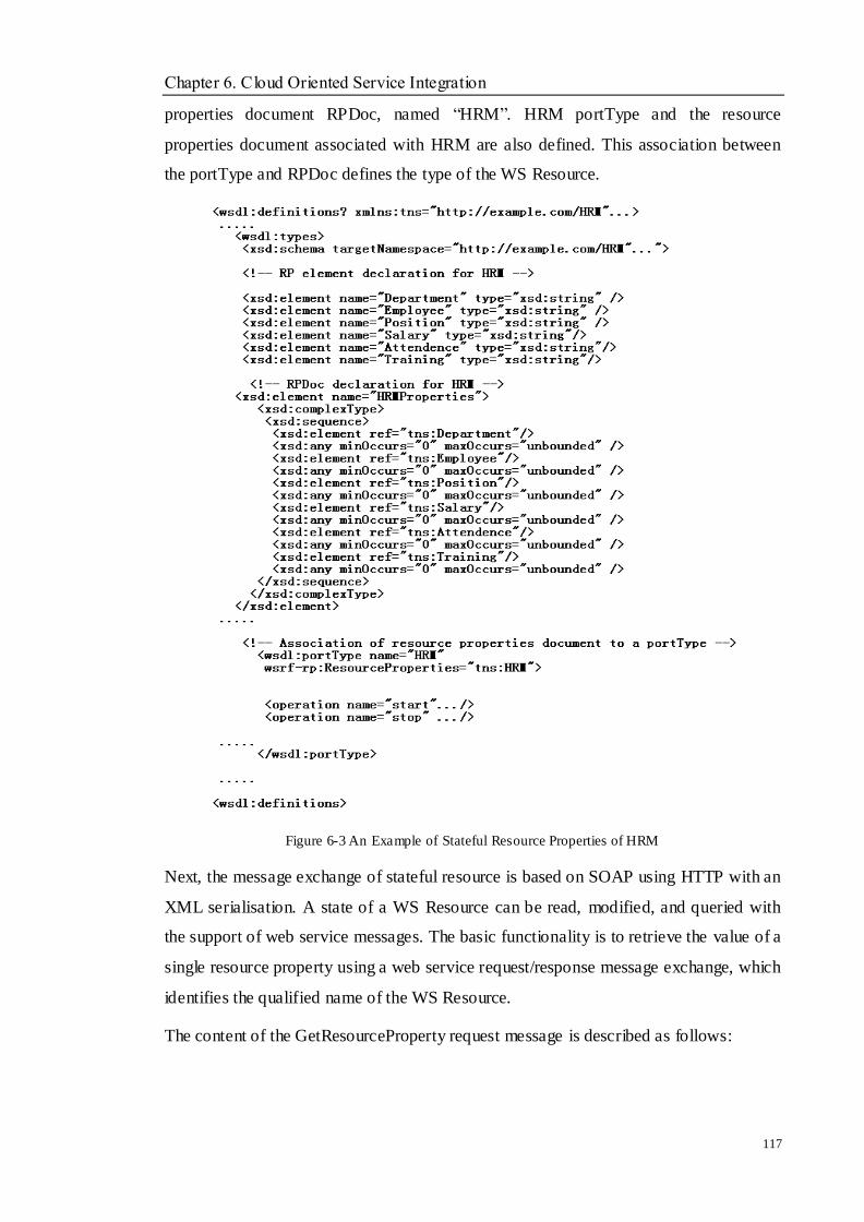
Chapter 6. Cloud Oriented Service Integration
117
properties document RPDoc, named ―HRM‖. HRM portType and the resource
properties document associated with HRM are also defined. This association between
the portType and RPDoc defines the type of the WS Resource.
Figure 6-3 An Example of Stateful Resource Properties of HRM
Next, the message exchange of stateful resource is based on SOAP using HTTP with an
XML serialisation. A state of a WS Resource can be read, modified, and queried with
the support of web service messages. The basic functionality is to retrieve the value of a
single resource property using a web service request/response message exchange, which
identifies the qualified name of the WS Resource.
The content of the GetResourceProperty request message is described as follows:
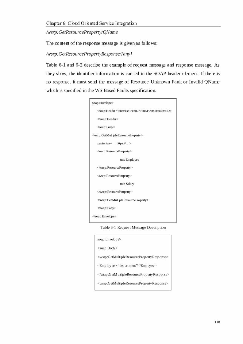
Chapter 6. Cloud Oriented Service Integration
118
/wsrp:GetResourceProperty/QName
The content of the response message is given as follows:
/wsrp:GetResourcePropertyResponse/{any}
Table 6-1 and 6-2 describe the example of request message and response message. As
they show, the identifier information is carried in the SOAP header element. If there is
no response, it must send the message of Resource Unknown Fault or Invalid QName
which is specified in the WS Based Faults specification.
soap:Envelope>
<soap:Header><tns:resourceID>HRM</tns:resourceID>
</soap:Header>
<soap:Body>
<wsrp:GetMultipleResourceProperty>
xmlns:tns= https://... >
<wsrp:ResourceProperty>
tns: Employee
</wsrp:ResourceProperty>
<wsrp:ResourceProperty>
tns: Salary
</wsrp:ResourceProperty>
</wsrp:GetMultipleResourceProperty>
</soap:Body>
</soap:Envelope>
Table 6-1 Request Message Description
soap:Envelope>
<soap:Body>
<wsrp:GetMultipleResourcePropertyResponse>
<Employee> ―department‖</Empoyee>
</wsrp:GetMultipleResourcePropertyResponse>
<wsrp:GetMultipleResourcePropertyResponse>
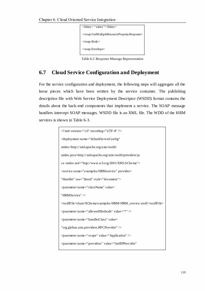
Chapter 6. Cloud Oriented Service Integration
119
<Salary> ―salary‖</Salary>
</wsrp:GetMultipleResourcePropertyResponse>
</soap:Body>
</soap:Envelope>
Table 6-2 Response Message Representation
6.7 Cloud Service Configuration and Deployment
For the service configuration and deployment, the following steps will aggregate all the
loose pieces which have been written by the service container. The publishing
description file with Web Service Deployment Descriptor (WSDD) format contains the
details about the back-end components that implement a service. The SOAP message
handlers intercept SOAP messages. WSDD file is an XML file. The WDD of the HRM
services is shown in Table 6-3.
<?xml version="1.0" encoding="UTF-8" ?>
<deployment name="defaultServerConfig"
xmlns=http://xml.apache.org/axis/wsdd/
xmlns:java=http://xml.apache.org/axis/wsdd/providers/ja
va xmlns:xsd="http://www.w3.org/2001/XMLSChema">
<service name="examples/HRMservice" provider=
"Handler" use="literal" style="document">
<parameter name="className" value=
"HRMService" />
<wsdlFile>share/SChema/examples/HRM/HRM_service.wsdl</wsdlFile>
<parameter name="allowedMethods" value="*" />
<parameter name="handlerClass" value=
"org.globus.axis.providers.RPCProvider" />
<parameter name="scope" value="Application" />
<parameter name="providers" value="GetRPProvider"

Chapter 6. Cloud Oriented Service Integration
120
/>
<parameter name="loadOnStartup" value="true" />
</service>
</deployment>
Table 6-3 The WSDD Configuration of HRM Services
In a Cloud environment, users should be able to access the created Cloud services
through a high- level friendly Cloud portal. Currently, there are four Cloud deployment
models [4]. They are Private Cloud, Public Cloud, Hybrid Cloud and Community Cloud.
The deployment methods can be found on those service companies ‘ web. A brief
introduction for each deployment model is given as follows.
Private Cloud. The cloud infrastructure is provisioned for exclusive use by a
single organisation comprising multiple consumers (e.g., business units). It may
be owned, managed, and operated by the organisation or a third party.
Public Cloud. The cloud infrastructure is provisioned for open use by the
general public. It may be owned, managed, and operated by business, academic
or government organisations.
Hybrid Cloud. The cloud infrastructure is a composition of two or more distinct
cloud infrastructures (private, public, or community) that keep unique entities,
but are bound together by standardised techniques that enable data and
application portability.
Community Cloud. The Cloud infrastructure is provisioned for exclusive use
by a specific community of consumers, from organisations that have shared
concerns including mission, security requirements, policy, and compliance
considerations. It may be owned, managed, and operated by one or more
organisations or a third party, or a combination of them.
No matter what Cloud service model is selected, some modules should be added to
extend the original framework:
Dictionary Services. It can supply an index of all available components and data
sources for system utilisation.
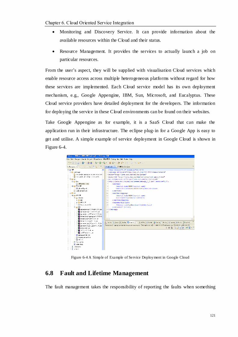
Chapter 6. Cloud Oriented Service Integration
121
Monitoring and Discovery Service. It can provide information about the
available resources within the Cloud and their status.
Resource Management. It provides the services to actually launch a job on
particular resources.
From the user‘s aspect, they will be supplied with visualisation Cloud services which
enable resource access across multiple heterogeneous platforms without regard for how
these services are implemented. Each Cloud service model has its own deployment
mechanism, e.g., Google Appengine, IBM, Sun, Microsoft, and Eucalyptus. These
Cloud service providers have detailed deployment for the developers. The information
for deploying the service in these Cloud environments can be found on their websites.
Take Google Appengine as for example, it is a SaaS Cloud that can make the
application run in their infrastructure. The eclipse plug- in for a Google App is easy to
get and utilise. A simple example of service deployment in Google Cloud is shown in
Figure 6-4.
Figure 6-4 A Simple of Example of Service Deployment in Google Cloud
6.8 Fault and Lifetime Management
The fault management takes the responsibility of reporting the faults when something
Chapter 6. Cloud Oriented Service Integration
122
goes wrong during the execution of a WS Service. The WS based Faults specification
[55] defines an XML schema type for a base fault, along with the rules for how this
fault type is conducted by the Web services. To address the issue, an XML schema
definition must be defined and associated with the semantics for fault information. The
definition is set by having a common base set of information that all the fault contents
include. It is noted that the approach simply defines the base format for the faults
without changing the WSDL message model.
Life management can trace each WS Resource Property and updates their state
following a series of resource requests. The WS Resource Lifetime management defines
the equal message exchange. If a service requestor wants to destroy a WS Resource, it
must utilise the WS Resource qualified end state reference to send the destroy message
to the web service provider. There are two ways to destroy a service request, namely an
immediate way and a scheduled way. They both provide the flexibility to design how
their service applications can clean up requests that are no longer required.
6.9 Summary
Cloud can supply a server infrastructure to achieve e-utilities requirements that can be
easily paid on demand to meet specific customer needs and business success. It supports
dynamic resource allocation in accordance with service level agreement policies and
reuse of the IT infrastructure at the higher utilisation level, and handling the
management from the network edge to application and data servers. Meanwhile, the real
time configuration can reduce time and cost and advance service reuse efficiently. The
chapter presents an EBS based framework that integrates the XML packaged legacy
system resources into the Cloud service environment. The stateful resources are defined
and building the Cloud services based on ESB components. The work on how to
implement the integration has been conducted in this Chapter:
The ESB based integration architecture is proposed, which combines the
advantages of web service techniques including WSDL based on SOAP to build the
interface defined by WSDL.

Chapter 6. Cloud Oriented Service Integration
123
The service implementation can be completed by using its qualified name (QName)
that is easy to be written by Java.
The WSDD configuration for the defined services registration is described and
current Cloud service deployment models are introduce to deploy the Cloud
services.
Chapter 7. Case Studies
124
Chapter 7 Case Studies
Objectives
__________________________________________________________________
To show how to use the related tools in the proposed approach.
To introduce how to use the introduced core techniques on implementing the
legacy system assessment and identification, Cloud oriented Service evolution
and Cloud oriented service integration.
_________________________________________________________________
7.1 Introduction
This chapter presents the case studies related to decomposing legacy systems, evolving
a legacy system into and within a Cloud environment and integrating the services into a
Cloud service framework. There are five core techniques proposed in this thesis for
Cloud service oriented legacy system evolution: AHP techniques, program slicing,
hierarchical cluster, program and model transformation, and Cloud service
infrastructure and framework. In this chapter, the case studies have been conducted for
these proposed techniques respectively. The case studies have been experimented with
the proposed approach and resulting prototype.
7.2 Experimentation of Software Toolkit
7.2.1 Eclipse
When considering the choice of tools to support the proposed approach, Eclipse is
chosen as a platform to integrate all related tools. Eclipse is an open development
platform that could integrate most plugs- in. The Eclipse platform contains a small micro
kernel and other functional parts are written as a plug- in. The small micro kernel will
help to load each plug- in. Developers can extend Eclipse by writing extensions to the
predefined extension points. Because of the openness of the Eclipse platform, many
Chapter 7. Case Studies
125
tools have been developed as Eclipse plug- ins, e.g., the Google Plug- in for Eclipse is a
set of software development tools that enables Java developers to quickly design, build,
optimise, and deploy cloud-based applications, EMF for generating UML and code,
XML tool and so on. Using the Eclipse platform opens the potential to link the tool with
a network of other Eclipse plug- in contributions and aims to simplify the number of
different, bespoke tools used in software engineering as a whole.
Eclipse was originally developed by IBM as the successor of its Visual Age family of
tools. Eclipse is now managed by the Eclipse Foundation, an independent not for profit
consortium of software industry vendors. It is a free software/open source
platform-independent software framework for delivering what the project calls
―rich-client applications‖, as opposed to ―thin client‖ browser-based applications. So
far this framework has typically been used to develop Integrated Development
Environments (IDE), such as the Java IDE called Java Development Toolkit (JDT) and
compiler that comes as part of Eclipse (and which is also used to develop Eclipse itself).
Eclipse is an open source community, whose projects are focused on building an open
development platform comprised of extensible frameworks, tools and runtimes for
building, deploying and managing software across the lifecycle. A large and vibrant
ecosystem of major technology vendors, innovative start-ups, universities, research
institutions and individuals extend, complement and support the Eclipse platform.
The Eclipse tool integration platform is a very popular, very extensible,
well-documented IDE that can be configured to host all of the useful development
activities from coding to deployment to debugging. The Eclipse IDE can be used to
manage all of these artefacts within a single project abstraction and coordinate all of the
useful development activities from coding to deployment to debugging. This thesis will
use its Java project abstraction to manage the artefacts, such as: source files, WSDLs,
client and server stubs, deployment configuration files, etc.
7.2.2 FermaT
Maintainer‗s Assistant has evolved into an industrial-strength re-engineering tool,
FermaT, which allows transformations and code simplification to be carried out
automatically. The FermaT tool was also designed to use WSL and has applications in
Chapter 7. Case Studies
126
the following areas:
Improve the maintainability of existing mission-critical software.
Translate programs into modern programming languages. FermaT often
translates programs written in an obsolete assembler language to more modern
languages such as C, Java.
Extract reusable components from the current system, deriving their
specifications, and storing the specifications, implementation, and development
strategy.
Reverse engineering existing systems to high- level specifications, followed by
subsequent re-engineering and evolutionary development.
7.2.3 Architecture Tool: AGG
AGG [122] is a well-established tool environment for algebraic graph transformation
systems, and has been developed and extended since over 15 years ago. Graphs in AGG
are defined by a type graph with node type inheritance and may be attributed by any
kind of Java objects. The arbitrary computations on these Java objects described by Java
expressions can be equipped with the Graph transformations.
A graphical user interface comprising several visual editors, an interpreter, and a set of
validation tools constructs the AGG environment. The stepwise transformations of
graphs as well as rule applications are supported by the interpreter as long as possible.
Several kinds of validations which comprise graph parsing, consistencies checking of
graphs and convict and dependency detection by critical pair analysis of graph rules are
provided by AGG support. Furthermore, checking the applicability of rule sequences is
supported, as well. Applications of AGG include graph and rule-based modelling of
software, validation of system properties by assigning a graph transformation based
semantics to some system model, graph transformation based evolution of software, and
the definition of visual languages based on graph grammars.
7.2.4 Google App Engine
The Google Plug-in for Eclipse [50] allows you to easily create and deploy App
Engine applications. For simplifying App Engine development, the Google Plug- in for
Chapter 7. Case Studies
127
Eclipse provides the following features:
Creating App Engine application with a new web application wizard.
Cloud SQL tooling to use Cloud SQL as a database for supporting the App
Engine application.
Importing the latest Google APIs
App Engine connected Android project Wizard to use App Engine as a backend
for your Android projects
Cloud Endpoints support, which provides simpler client access to App Engine
backbends.
One-click deploy to App Engine
The Google Plug- in for Eclipse also assists developers in efficiently creating a rich user
experience, generating a high quality Ajax code using the Google Web Toolkit,
optimizing performance with Speed Tracer, and effortlessly deploying applications to
the App Engine.
These powerful tools remove tedium and free developers to focus on creating great
application logic. The Google Plug- in for Eclipse is the first suite of integrated
development tools designed specifically for Eclipse Java developers to create fast,
reliable and high quality applications for the Google cloud.
7.3 Legacy System Analysis
To assess whether the legacy system could be selected to evolve with Cloud features;
the proposed approach has been applied to human resource management (HRM) as
shown in Appendix A. This instance is free to download on CSDN for academic
purposes with source code, which is free to use, modify, and to be changed to suit
personal requirements.
It is an automated software system for Human Resource Management, which deals with
information about employees. It uses the files to handle a series of activities for an
employee in the company or other organisation.
Chapter 7. Case Studies
128
The HRM system performs the following functions:
Department Management
Employee Information Management
Position and Salary Management
Attendance Management
Training Management.
This HRM system is not completed HRM software, it is just designed to meet the
requirements of the company or other organisation, but it can still manage all the
information of the employee using the files at the backend. In this case study, this HRM
system is nominated as a legacy HRM system, which is intended to be reengineered and
evolved into the Cloud service environment.
As discussed in Chapter 4, an assessment based AHP framework is given to judge
whether the legacy system is valuable to conduct the proposed approach. Hence, the
assessment process can be described.
For the system, the final goal will be defined: evolution (E), partial evolution (PE) and
redevelopment (RD), and there are three factors that can be considered as the criteria
during the evolution process, namely scalability, flexibility and availability.
First, the relationship between the three goals and the selected criteria can easily be
required by the existing discussion from current main organisations, which can be
preparation for the prediction process.
Next, according to the AHP‘s methodology and the relationship between the goals and
criteria, the comparisons among the three goals on each criterion can be calculated.
After the comparisons, the goal can be selected to be utilised for the evolution. The
following three tables give the comparisons. The calculation rules can be obtained in
Chapter 4. The calculation results are shown in Table 7-1, 7-2 and 7-3.
Scalability

Chapter 7. Case Studies
129
PE E RD
PE 1 5 9
E 1/5 1 3
RD 1/9 1/3 1
Table 7-1 Relat ive Data Matrix among Three Goals on Scalability Criteria
This means that PE is better than E in terms of scalability and even more strongly than
RD. The values for the matrix is (0.751, 0.178, 0.071), and the ratio is 0.072, and the
consistent is not over 1 and is fine.
Flexibility
PE E RD
PE 1 1 5
E 1 1 3
RD 1/5 1/3 1
Table 7-2 Relat ive Data Matrix among Three Goals on Flexib ility Criteria
This means that PE is similar with in terms of flexibility but stronger than RD. The
value for the matrix is (0.480, 0.406, 0.114), the ratio is 0.026, and the consistent is still
not over 1 and is fine.
Availability
RD PE E
RD 1 1/9 1/5
PE 9 1 2
E 5 1/2 1
Table 7-3 Relat ive Data Matrix among Three Goals on Availability Criteria
This means that PE is the best solutions on the availability Criteria. The computed value
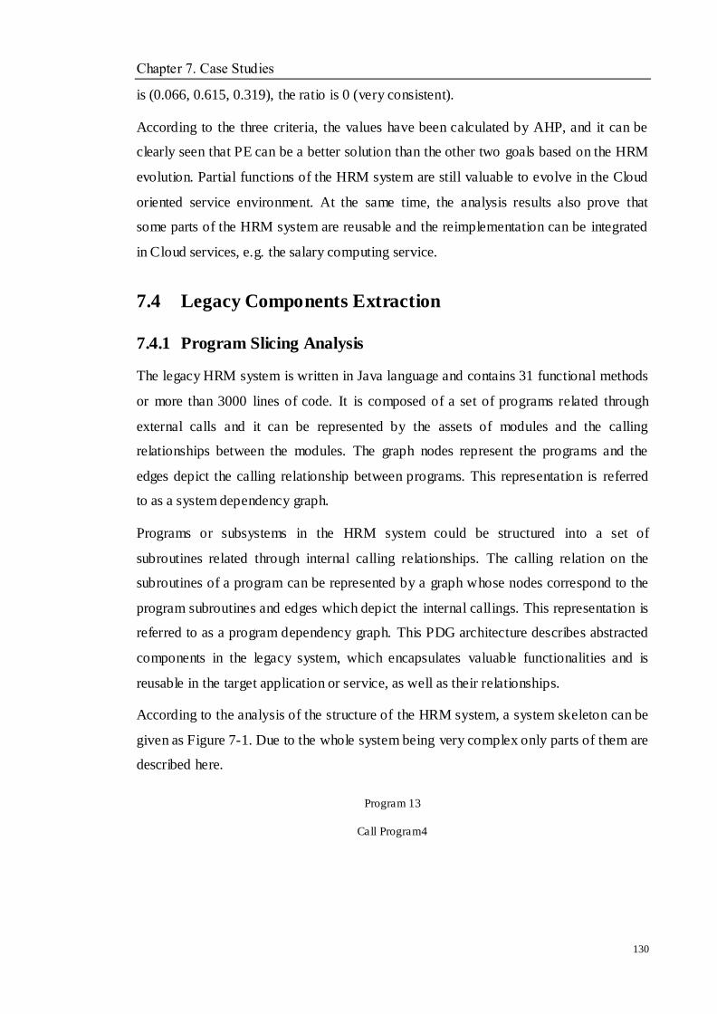
Chapter 7. Case Studies
130
is (0.066, 0.615, 0.319), the ratio is 0 (very consistent).
According to the three criteria, the values have been calculated by AHP, and it can be
clearly seen that PE can be a better solution than the other two goals based on the HRM
evolution. Partial functions of the HRM system are still valuable to evolve in the Cloud
oriented service environment. At the same time, the analysis results also prove that
some parts of the HRM system are reusable and the reimplementation can be integrated
in Cloud services, e.g. the salary computing service.
7.4 Legacy Components Extraction
7.4.1 Program Slicing Analysis
The legacy HRM system is written in Java language and contains 31 functional methods
or more than 3000 lines of code. It is composed of a set of programs related through
external calls and it can be represented by the assets of modules and the calling
relationships between the modules. The graph nodes represent the programs and the
edges depict the calling relationship between programs. This representation is referred
to as a system dependency graph.
Programs or subsystems in the HRM system could be structured into a set of
subroutines related through internal calling relationships. The calling relation on the
subroutines of a program can be represented by a graph whose nodes correspond to the
program subroutines and edges which depict the internal callings. This representation is
referred to as a program dependency graph. This PDG architecture describes abstracted
components in the legacy system, which encapsulates valuable functionalities and is
reusable in the target application or service, as well as their relationships.
According to the analysis of the structure of the HRM system, a system skeleton can be
given as Figure 7-1. Due to the whole system being very complex only parts of them are
described here.
Program 13
Call Program4
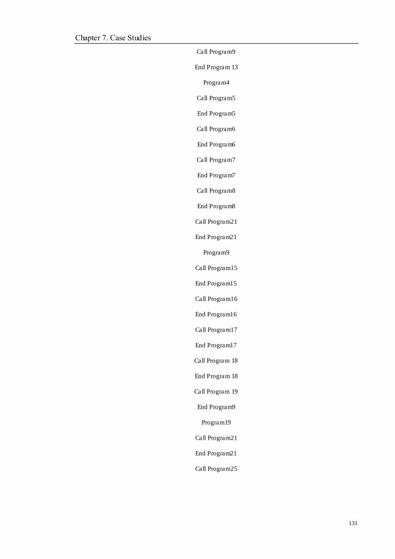
Chapter 7. Case Studies
131
Call Program9
End Program 13
Program4
Call Program5
End Program5
Call Program6
End Program6
Call Program7
End Program7
Call Program8
End Program8
Call Program21
End Program21
Program9
Call Program15
End Program15
Call Program16
End Program16
Call Program17
End Program17
Call Program 18
End Program 18
Call Program 19
End Program9
Program19
Call Program21
End Program21
Call Program25
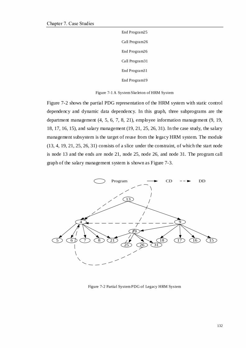
Chapter 7. Case Studies
132
End Program25
Call Program26
End Program26
Call Program31
End Program31
End Program19
Figure 7-1 A System Skeleton of HRM System
Figure 7-2 shows the partial PDG representation of the HRM system with static control
dependency and dynamic data dependency. In this graph, three subprograms are the
department management (4, 5, 6, 7, 8, 21), employee information management (9, 19,
18, 17, 16, 15), and salary management (19, 21, 25, 26, 31). In the case study, the salary
management subsystem is the target of reuse from the legacy HRM system. The module
(13, 4, 19, 21, 25, 26, 31) consists of a slice under the constraint, of which the start node
is node 13 and the ends are node 21, node 25, node 26, and node 31. The program call
graph of the salary management system is shown as Figure 7-3.
4
25
19
18
Program CD DD
16
9
17
13
6 7 8
26 31
5 21 15
Figure 7-2 Partial System PDG of Legacy HRM System
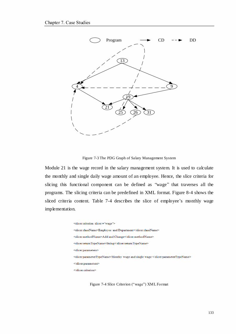
Chapter 7. Case Studies
133
4
25
19
Program CD DD
9
13
26 31
21
Figure 7-3 The PDG Graph of Salary Management System
Module 21 is the wage record in the salary management system. It is used to calculate
the monthly and single daily wage amount of an employee. Hence, the slice criteria for
slicing this functional component can be defined as ―wage‖ that traverses all the
programs. The slicing criteria can be predefined in XML format. Figure 8-4 shows the
sliced criteria content. Table 7-4 describes the slice of employee‘s monthly wage
implementation.
Figure 7-4 Slice Criterion (―wage‖) XML Format
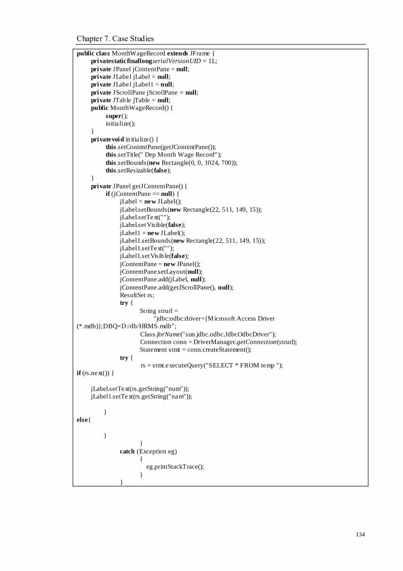
Chapter 7. Case Studies
134
public class MonthWageRecord extends JFrame {
privatestaticfinallongserialVersionUID = 1L;
private JPanel jContentPane = null;
private JLabel jLabel = null;
private JLabel jLabel1 = null;
private JScrollPane jScrollPane = null;
private JTab le jTable = null;
public MonthWageRecord() {
super();
initialize();
}
privatevoid in itialize() {
this .setContentPane(getJContentPane());
this .setTitle(" Dep Month Wage Record");
this .setBounds(new Rectangle(0, 0, 1024, 700));
this .setResizable(false);
}
private JPanel getJContentPane() {
if (jContentPane == null) {
jLabel = new JLabel();
jLabel.setBounds(new Rectangle(22, 511, 149, 15));
jLabel.setText("");
jLabel.setVisible(false);
jLabel1 = new JLabel();
jLabel1.setBounds(new Rectangle(22, 511, 149, 15));
jLabel1.setText("");
jLabel1.setVisib le(false);
jContentPane = new JPanel();
jContentPane.setLayout(null);
jContentPane.add(jLabel, null);
jContentPane.add(getJScrollPane(), null);
ResultSet rs;
try {
St ring strurl =
"jdbc:odbc:driver={Microsoft Access Driver
(*.mdb)};DBQ=D:/db/HRMS.mdb";
Class.forName("sun.jdbc.odbc.JdbcOdbcDriver");
Connection conn = DriverManager.getConnection(strurl);
Statement stmt = conn.createStatement();
try {
rs = stmt.executeQuery("SELECT * FROM temp ");
if (rs.next()) {
jLabel.setText(rs.getString("num"));
jLabel1.setText(rs.getString("nam"));
}
else{
}
}
catch (Exception eg)
{
eg.printStackTrace();
}
}
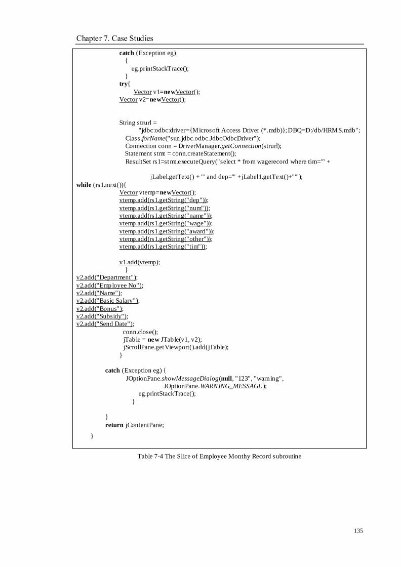
Chapter 7. Case Studies
135
catch (Exception eg)
{
eg.printStackTrace();
}
try{
Vector v1=newVector();
Vector v2=newVector();
String strurl =
"jdbc:odbc:driver={Microsoft Access Driver (*.mdb)};DBQ=D:/db/HRMS.mdb";
Class.forName("sun.jdbc.odbc.JdbcOdbcDriver");
Connection conn = DriverManager.getConnection(strurl);
Statement stmt = conn.createStatement();
ResultSet rs1=stmt.executeQuery("select * from wagerecord where tim='" +
jLabel.getText() + "' and dep='" +jLabel1.getText()+"'");
while (rs1.next()){
Vector vtemp=newVector();
vtemp.add(rs1.getString("dep"));
vtemp.add(rs1.getString("num"));
vtemp.add(rs1.getString("name"));
vtemp.add(rs1.getString("wage"));
vtemp.add(rs1.getString("award"));
vtemp.add(rs1.getString("other"));
vtemp.add(rs1.getString("tim"));
v1.add(vtemp);
}
v2.add("Department");
v2.add("Employee No");
v2.add("Name");
v2.add("Basic Salary");
v2.add("Bonus");
v2.add("Subsidy");
v2.add("Send Date");
conn.close();
jTab le = new JTab le(v1, v2);
jScrollPane.getViewport().add(jTable);
}
catch (Exception eg) {
JOptionPane.showMessageDialog(null, "123", "warn ing",
JOptionPane.WARNING_MESSAGE );
eg.printStackTrace();
}
}
return jContentPane;
}
Table 7-4 The Slice of Employee Monthy Record subroutine
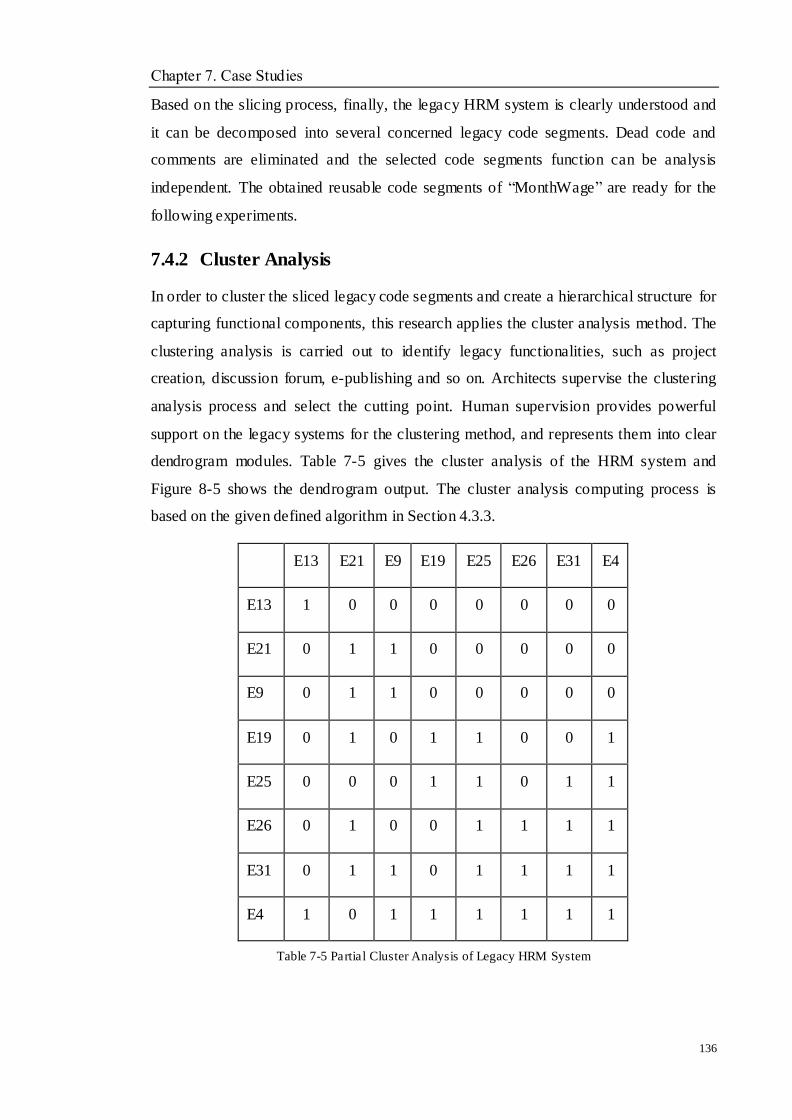
Chapter 7. Case Studies
136
Based on the slicing process, finally, the legacy HRM system is clearly understood and
it can be decomposed into several concerned legacy code segments. Dead code and
comments are eliminated and the selected code segments function can be analysis
independent. The obtained reusable code segments of ―MonthWage‖ are ready for the
following experiments.
7.4.2 Cluster Analysis
In order to cluster the sliced legacy code segments and create a hierarchical structure for
capturing functional components, this research applies the cluster analysis method. The
clustering analysis is carried out to identify legacy functionalities, such as project
creation, discussion forum, e-publishing and so on. Architects supervise the clustering
analysis process and select the cutting point. Human supervision provides powerful
support on the legacy systems for the clustering method, and represents them into clear
dendrogram modules. Table 7-5 gives the cluster analysis of the HRM system and
Figure 8-5 shows the dendrogram output. The cluster analysis computing process is
based on the given defined algorithm in Section 4.3.3.
E13 E21 E9 E19 E25 E26 E31 E4
E13 1 0 0 0 0 0 0 0
E21 0 1 1 0 0 0 0 0
E9 0 1 1 0 0 0 0 0
E19 0 1 0 1 1 0 0 1
E25 0 0 0 1 1 0 1 1
E26 0 1 0 0 1 1 1 1
E31 0 1 1 0 1 1 1 1
E4 1 0 1 1 1 1 1 1
Table 7-5 Partial Cluster Analysis of Legacy HRM System
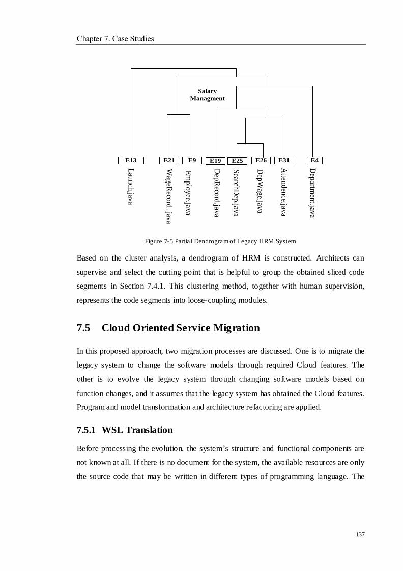
Chapter 7. Case Studies
137
E13 E21 E9 E25 E26 E31 E4
Salary
Managment
Lau
nch
,java
Wag
eReco
rd. jav
a
Em
plo
yee.jav
a
Dep
Wag
e.java
Search
Dep
.java
Atten
den
ce.java
Dep
artmen
t.java
E19
Dep
Reco
rd.jav
a
Figure 7-5 Partial Dendrogram of Legacy HRM System
Based on the cluster analysis, a dendrogram of HRM is constructed. Architects can
supervise and select the cutting point that is helpful to group the obtained sliced code
segments in Section 7.4.1. This clustering method, together with human supervision,
represents the code segments into loose-coupling modules.
7.5 Cloud Oriented Service Migration
In this proposed approach, two migration processes are discussed. One is to migrate the
legacy system to change the software models through required Cloud features. The
other is to evolve the legacy system through changing software models based on
function changes, and it assumes that the legacy system has obtained the Cloud features.
Program and model transformation and architecture refactoring are applied.
7.5.1 WSL Translation
Before processing the evolution, the system‘s structure and functional components are
not known at all. If there is no document for the system, the available resources are only
the source code that may be written in different types of programming language. The
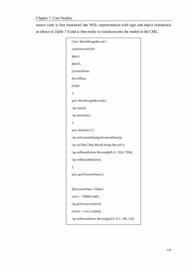
Chapter 7. Case Studies
138
source code is first translated into WSL representation with type and object orientation
as shown in Table 7-6 and is then ready to transform into the model in the CML.
Class MonthWageRecord {
serialVersionUID;
jlabe1;
jlabel1;
jContentPane;
jScro llPane
jTable
};
proc MonthwageRecord() {
!xp super();
!xp init ialize();
};
proc init ialize () {
!xp setContentPane(getJcontentPane());
!xp setTitle("Dep Month Wage Record");
!xp setBounds(new Rectangle(0, 0, 1024, 700));
!xp setResizable(false);
};
proc getJContentPane() {
if(jContentPane<>0)then
strul := "HRMS.mdb";
!xp getConnecton(strl);
jLabel := new JLabel();
!xp setBounds(new Rectangle(22, 511, 149, 15));
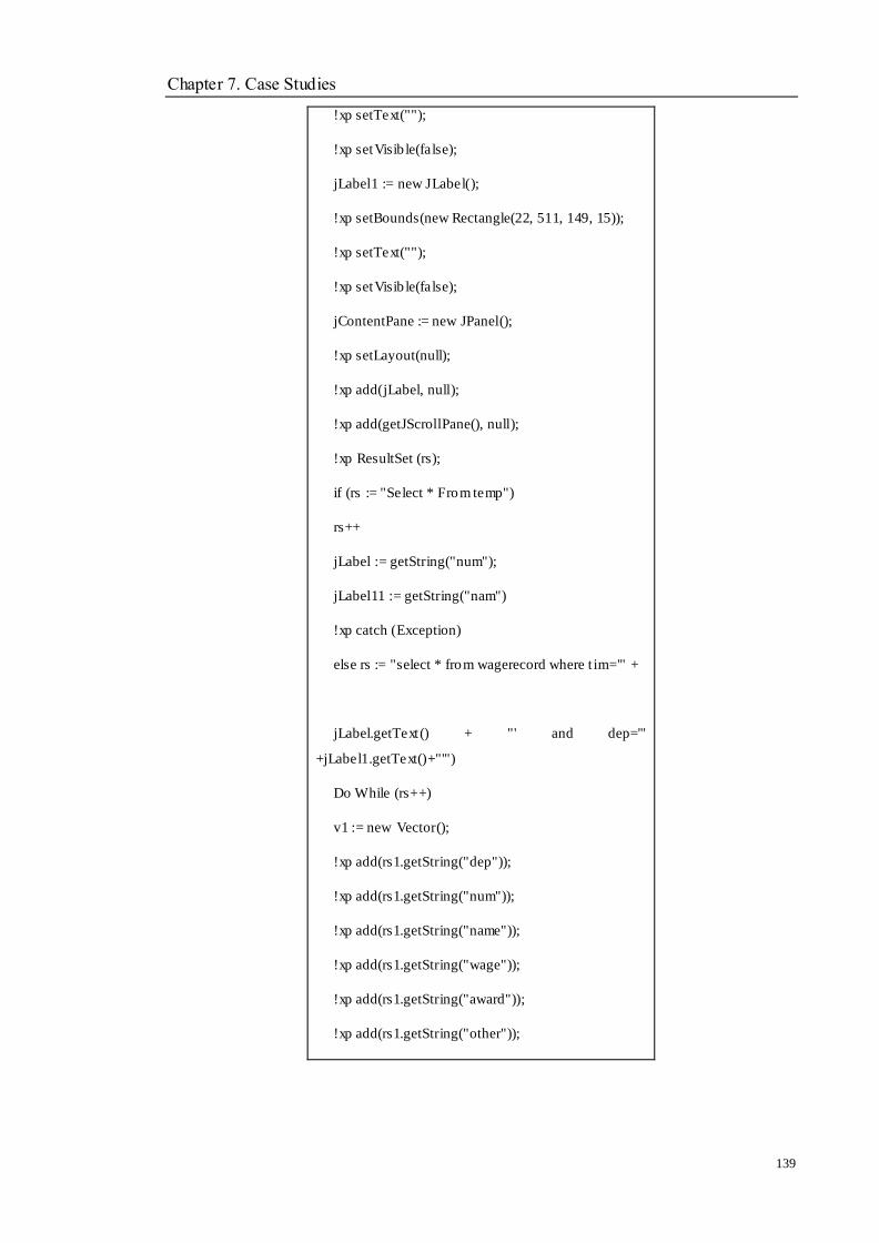
Chapter 7. Case Studies
139
!xp setText("");
!xp setVisib le(false);
jLabel1 := new JLabel();
!xp setBounds(new Rectangle(22, 511, 149, 15));
!xp setText("");
!xp setVisib le(false);
jContentPane := new JPanel();
!xp setLayout(null);
!xp add(jLabel, null);
!xp add(getJScrollPane(), null);
!xp ResultSet (rs);
if (rs := "Select * From temp")
rs++
jLabel := getString("num");
jLabel11 := getString("nam")
!xp catch (Exception)
else rs := "select * from wagerecord where t im='" +
jLabel.getText() + "' and dep='"
+jLabel1.getText()+"'")
Do While (rs++)
v1 := new Vector();
!xp add(rs1.getString("dep"));
!xp add(rs1.getString("num"));
!xp add(rs1.getString("name"));
!xp add(rs1.getString("wage"));
!xp add(rs1.getString("award"));
!xp add(rs1.getString("other"));

Chapter 7. Case Studies
140
!xp add(rs1.getString("tim"));
!xp add(v1)
OD;
v2 := new Vector();
!xp add("Department");
!xp add("Employee No");
!xp add("Name");
!xp add("Basic Salary");
!xp add("Bonus");
!xp add("Subsidy");
!xp add("Send Date");
!xp close(conn);
jTable = new JTable(v1, v2);
!xp jScrollPane (add(jTable));
!xp catch(Exception);
!xp printStackTrace();
!xp return(jContentPane)
}
proc main()
{
!xp MonthWageRecord (in itialize());
}
Table 7-6 Partial Code of ―MonthWageRecord‖ in WSL
Based on the WSL representation, the obtained code segments of MonthWage from
Section 7.4.1 and Section 7.4.2 are translated into an easy and simple format. Redundant
information is removed based on the defined transformation rules in Section 5.2.1. The
variables and corresponding functions are clear to understand. This representation is the
base of the model construction and transformation in the following steps.
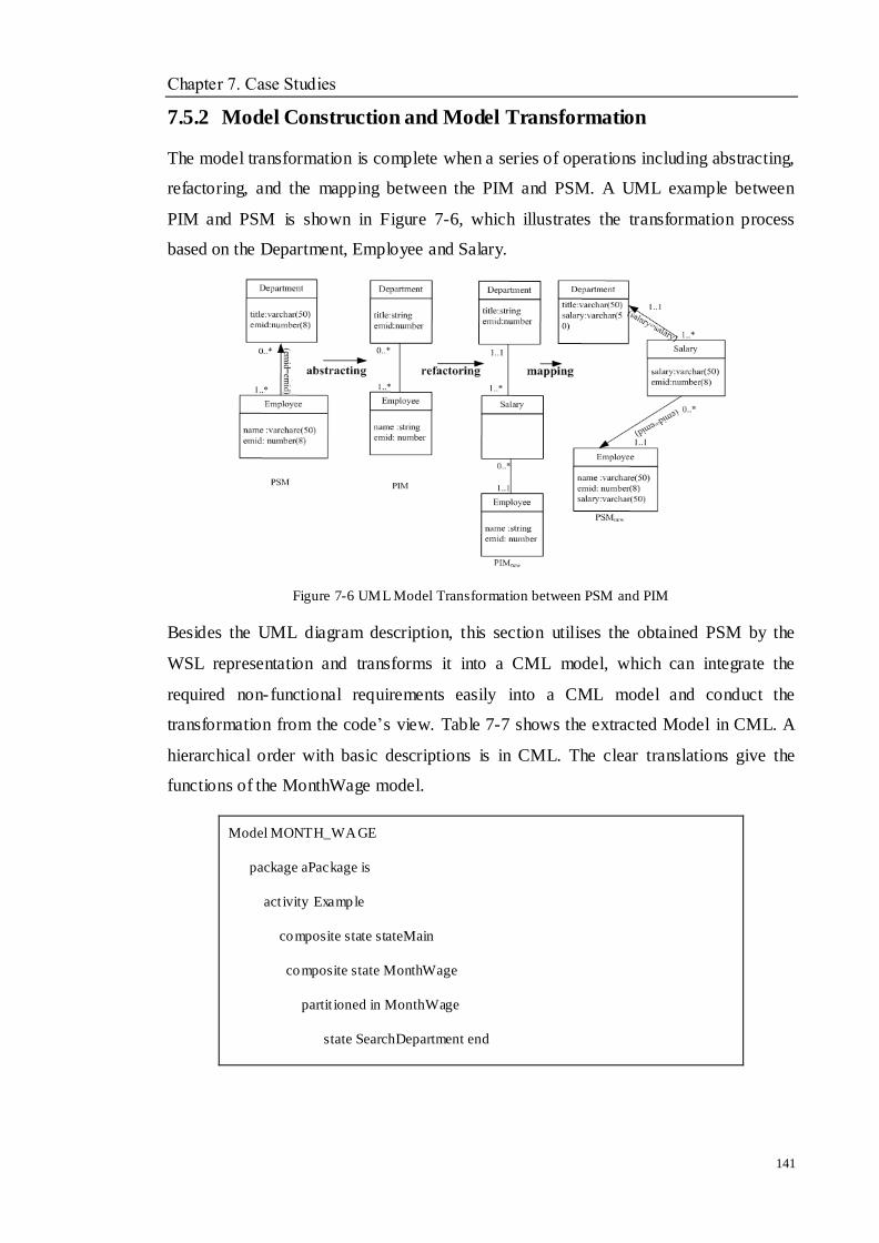
Chapter 7. Case Studies
141
7.5.2 Model Construction and Model Transformation
The model transformation is complete when a series of operations including abstracting,
refactoring, and the mapping between the PIM and PSM. A UML example between
PIM and PSM is shown in Figure 7-6, which illustrates the transformation process
based on the Department, Employee and Salary.
Figure 7-6 UML Model Transformation between PSM and PIM
Besides the UML diagram description, this section utilises the obtained PSM by the
WSL representation and transforms it into a CML model, which can integrate the
required non-functional requirements easily into a CML model and conduct the
transformation from the code‘s view. Table 7-7 shows the extracted Model in CML. A
hierarchical order with basic descriptions is in CML. The clear translations give the
functions of the MonthWage model.
Model MONTH_WAGE
package aPackage is
act ivity Example
composite state stateMain
composite state MonthWage
partit ioned in MonthWage
state SearchDepartment end
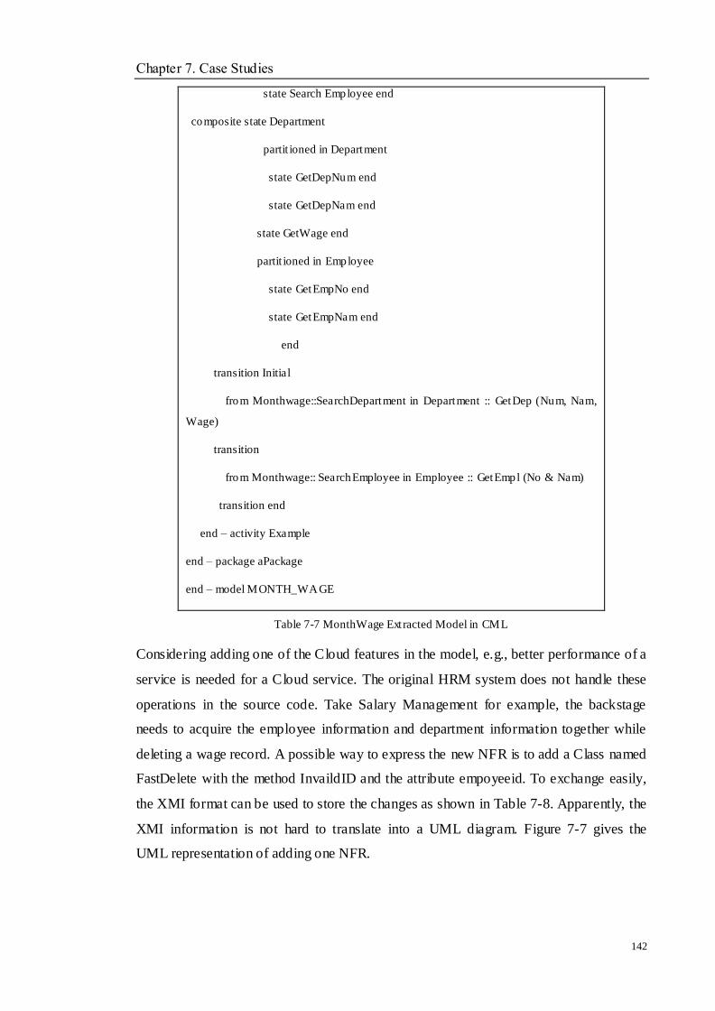
Chapter 7. Case Studies
142
state Search Employee end
composite state Department
partit ioned in Department
state GetDepNum end
state GetDepNam end
state GetWage end
partit ioned in Employee
state GetEmpNo end
state GetEmpNam end
end
transition Initial
from Monthwage::SearchDepartment in Department :: GetDep (Num, Nam,
Wage)
transition
from Monthwage:: SearchEmployee in Employee :: GetEmpl (No & Nam)
transition end
end – activity Example
end – package aPackage
end – model MONTH_WAGE
Table 7-7 MonthWage Extracted Model in CML
Considering adding one of the Cloud features in the model, e.g., better performance of a
service is needed for a Cloud service. The original HRM system does not handle these
operations in the source code. Take Salary Management for example, the backstage
needs to acquire the employee information and department information together while
deleting a wage record. A possible way to express the new NFR is to add a Class named
FastDelete with the method InvaildID and the attribute empoyeeid. To exchange easily,
the XMI format can be used to store the changes as shown in Table 7-8. Apparently, the
XMI information is not hard to translate into a UML diagram. Figure 7-7 gives the
UML representation of adding one NFR.

Chapter 7. Case Studies
143
<XMI.content>
<UML:Model xmi.id="NFR.1" name="Perfomance" visibility="public"
isSpecification="false" isRoot="false"
isLeaf="false" isAbstract="false">
<UML:Namespace.ownedElement>
<UML:Class xmi.id="C.1" name="FastDelete" visibility="public"
isSpecification="false" namespace="M.1"
isRoot="true"
isLeaf="true" isAbstract="false" isActive="false">
<UML:Classifier.feature>
<UML:Attribute xmi.id="A.1" name="employeeid" visibility="private"
isSpecification="false"
ownerScope="instance"/>
<UML:Method xmi.id="M.1" name="InvaildID" visibility="private"
isSpecification="false"
ownerScope="instance"/>
</UML:Classifier.feature>
</UML:Class>
</UML:Namespace.ownedElement>
</UML:Model>
</XMI.content>
Table 7-8 NFR Template XMI Format
FastDelete
-EmployeeID
+InvaildID():void
MonthWage
-EmployeeID:int
-Employee:string
-Department:string
-DepartmentID:int
-time:string
-wage:tring
….
+InvaildID():void
…
Employee
-EmployeeID:int
-Employee:string
-address:string
…
…
1 1 1*

Chapter 7. Case Studies
144
Figure 7-7 Adding NFR FastDelete
Based on the model construction and transformation, the corresponding PIM and PSM
are generated by CML syntax. The added Cloud features are described in UML class
diagram and transformed into CML format. Then, the CML description of added Cloud
features are integrated into the original model with the transformation rules defined in
Section 5.2.3 and Section 5.2.4. Meanwhile, all the model information is stored into an
XMI format that can be used in the Section 7.6.
7.5.3 Architecture Refactoring
When the functions change, the software architecture change is used to implement the
process. According to the proposed approach, the architecture will be expressed in
SADL as described in Section 5.3.2.2. Suppose the user wants to develop a new
Client-Server style system with a new function supporting transition online, the
architecture in SADL can be shown in Table 7-9.
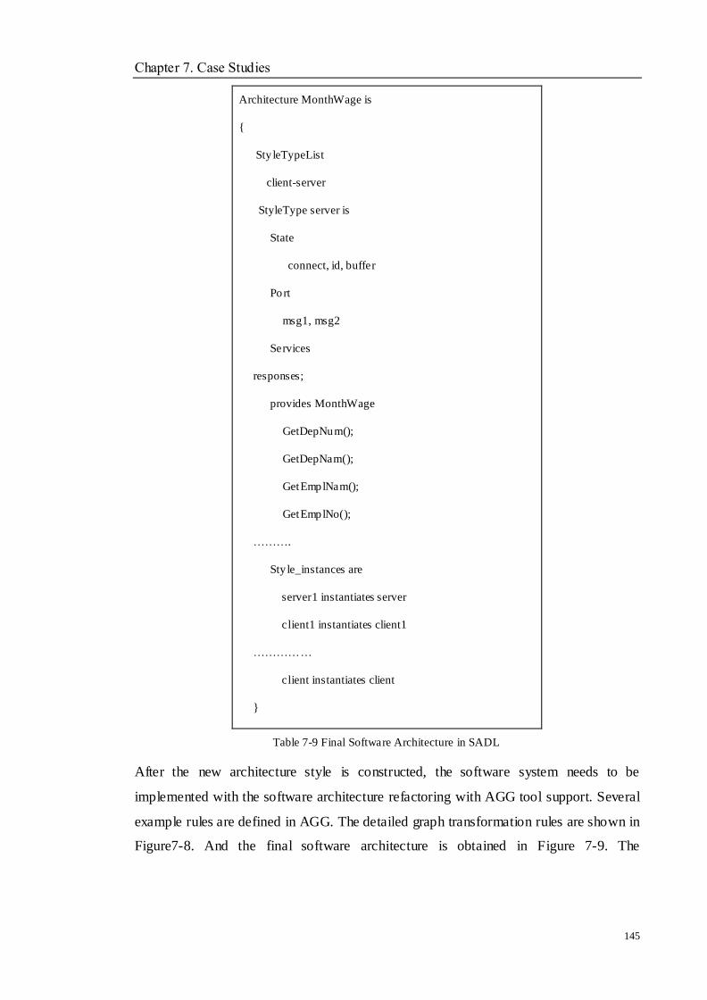
Chapter 7. Case Studies
145
Architecture MonthWage is
{
Sty leTypeList
client-server
StyleType server is
State
connect, id, buffer
Port
msg1, msg2
Services
responses;
provides MonthWage
GetDepNum();
GetDepNam();
GetEmplNam();
GetEmplNo();
……….
Sty le_instances are
server1 instantiates server
client1 instantiates client1
……………
client instantiates client
}
Table 7-9 Final Software Architecture in SADL
After the new architecture style is constructed, the software system needs to be
implemented with the software architecture refactoring with AGG tool support. Several
example rules are defined in AGG. The detailed graph transformation rules are shown in
Figure7-8. And the final software architecture is obtained in Figure 7-9. The
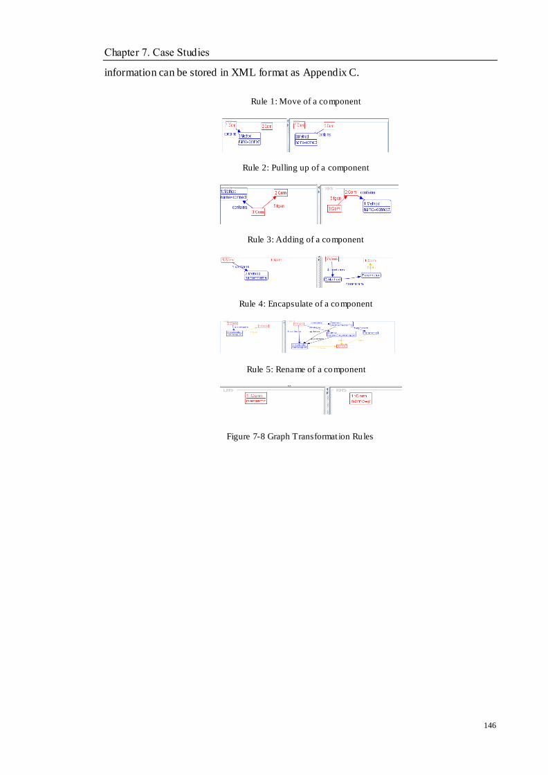
Chapter 7. Case Studies
146
information can be stored in XML format as Appendix C.
Rule 1: Move of a component
Rule 2: Pulling up of a component
Rule 3: Adding of a component
Rule 4: Encapsulate of a component
Rule 5: Rename of a component
Figure 7-8 Graph Transformat ion Rules

Chapter 7. Case Studies
147
Figure 7-9 Software Architecture Refactoring in AGG
The architecture refactoring is applied to the migration ―WITHIN‖ the Cloud
environment. SADL representation is utilised to change the architecture style and
re-construct the architecture of the legacy system. CS style is regarded as the suitable
architecture style of a software system in a Cloud environment. The related discussions
are given in Section 5.3.2.1. Hence, the architecture style of PP is transformed to the CS
style with the pre-defined algorithm. Based on the representation of the software
architecture style, the system architecture is redesigned with the support of AGG tool.
The developers can implement the code with the new architecture description.
According to the operations in Sections 7.4 and 7.5, the Cloud-oriented HRM
application is obtained. The following steps discuss how to integrate it into a Cloud
service and run in Cloud environments.
7.6 Cloud Service Integration
This section discusses how to develop and deploy a simple Google Appengine Cloud
service. The eclipse is used to help the developer handle all tedious files, e.g., XML
files and WSDL files.
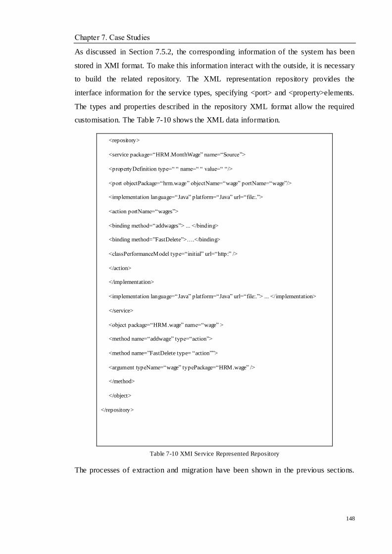
Chapter 7. Case Studies
148
As discussed in Section 7.5.2, the corresponding information of the system has been
stored in XMI format. To make this information interact with the outside, it is necessary
to build the related repository. The XML representation repository provides the
interface information for the service types, specifying <port> and <property>elements.
The types and properties described in the repository XML format allow the required
customisation. The Table 7-10 shows the XML data information.
<repository>
<service package=―HRM.MonthWage‖ name=―Source‖>
<propertyDefinition type=― ― name=― ― value=― ―/>
<port objectPackage=―hrm.wage‖ objectName=―wage‖ portName=―wage‖/>
<implementation language=―Java‖ platform=―Java‖ url=―file:.‖>
<action portName=―wages‖>
<binding method=―addwages‖> ... </binding>
<binding method=‖FastDelete‖>….</binding>
<classPerformanceModel type=―initial‖ url=―http:‖ />
</action>
</implementation>
<implementation language=―Java‖ platform=―Java‖ url=―file:.‖> ... </implementation>
</service>
<object package=―HRM.wage‖ name=―wage‖ >
<method name=―addwage‖ type=―action‖>
<method name=‖FastDelete type= ―action‖‖>
<argument typeName=―wage‖ typePackage=―HRM.wage‖ />
</method>
</object>
</repository>
Table 7-10 XMI Service Represented Repository
The processes of extraction and migration have been shown in the previous sections.
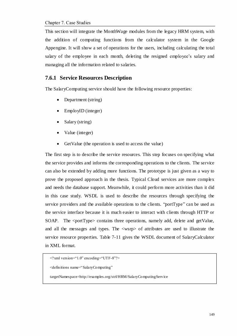
Chapter 7. Case Studies
149
This section will integrate the MonthWage modules from the legacy HRM system, with
the addition of computing functions from the calculator system in the Google
Appengine. It will show a set of operations for the users, including calculating the total
salary of the employee in each month, deleting the resigned employee‘s salary and
managing all the information related to salaries.
7.6.1 Service Resources Description
The SalaryComputing service should have the following resource properties:
Department (string)
EmployID (integer)
Salary (string)
Value (integer)
GetValue (the operation is used to access the value)
The first step is to describe the service resources. This step focuses on specifying what
the service provides and informs the corresponding operations to the clients. The service
can also be extended by adding more functions. The prototype is just given as a way to
prove the proposed approach in the thesis. Typical Cloud services are more complex
and needs the database support. Meanwhile, it could perform more activities than it did
in this case study. WSDL is used to describe the resources through specifying the
service providers and the available operations to the clients. ―portType‖ can be used as
the service interface because it is much easier to interact with clients through HTTP or
SOAP. The <portType> contains three operations, namely add, delete and getValue,
and all the messages and types. The <wsrp> of attributes are used to illustrate the
service resource properties. Table 7-11 gives the WSDL document of SalaryCalculator
in XML format.
<?xml version=―1.0‖ encoding=―UTF-8‖?>
<defin itions name=―SalaryComputing‖
targetNamespace=http://examples.org/strl/HRM/SalaryComputingServ ice
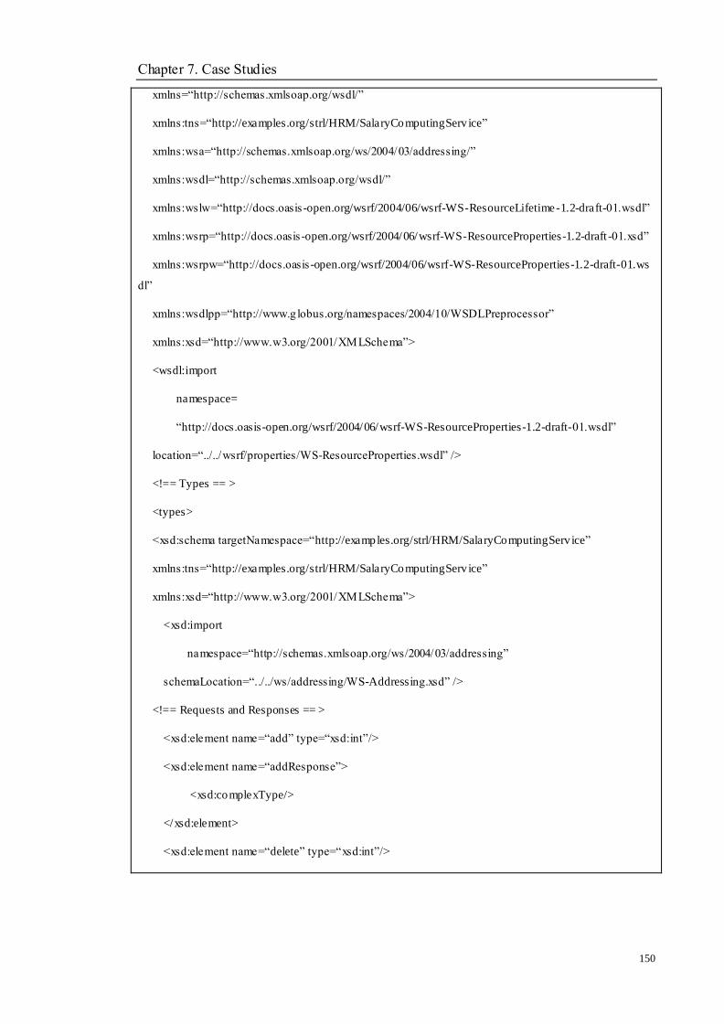
Chapter 7. Case Studies
150
xmlns=―http://schemas.xmlsoap.org/wsdl/‖
xmlns:tns=―http://examples.org/strl/HRM/SalaryComputingServ ice‖
xmlns:wsa=―http://schemas.xmlsoap.org/ws/2004/03/addressing/‖
xmlns:wsdl=―http://schemas.xmlsoap.org/wsdl/‖
xmlns:wslw=―http://docs.oasis -open.org/wsrf/2004/06/wsrf-WS-ResourceLifetime-1.2-draft-01.wsdl‖
xmlns:wsrp=―http://docs.oasis -open.org/wsrf/2004/06/wsrf-WS-ResourceProperties-1.2-draft -01.xsd‖
xmlns:wsrpw=―http://docs.oasis -open.org/wsrf/2004/06/wsrf-WS-ResourceProperties-1.2-draft-01.ws
dl‖
xmlns:wsdlpp=―http://www.g lobus.org/namespaces/2004/10/WSDLPreprocessor‖
xmlns:xsd=―http://www.w3.org/2001/XMLSchema‖>
<wsdl:import
namespace=
―http://docs.oasis-open.org/wsrf/2004/06/wsrf-WS-ResourceProperties-1.2-draft-01.wsdl‖
location=―../../wsrf/properties/WS-ResourceProperties.wsdl‖ />
<!== Types == >
<types>
<xsd:schema targetNamespace=―http://examples.org/strl/HRM/SalaryComputingServ ice‖
xmlns:tns=―http://examples.org/strl/HRM/SalaryComputingServ ice‖
xmlns:xsd=―http://www.w3.org/2001/XMLSchema‖>
<xsd:import
namespace=―http://schemas.xmlsoap.org/ws/2004/03/addressing‖
schemaLocation=―../../ws/addressing/WS-Addressing.xsd‖ />
<!== Requests and Responses == >
<xsd:element name=―add‖ type=―xsd:int‖/>
<xsd:element name=―addResponse‖>
<xsd:complexType/>
</xsd:element>
<xsd:element name=―delete‖ type=―xsd:int‖/>
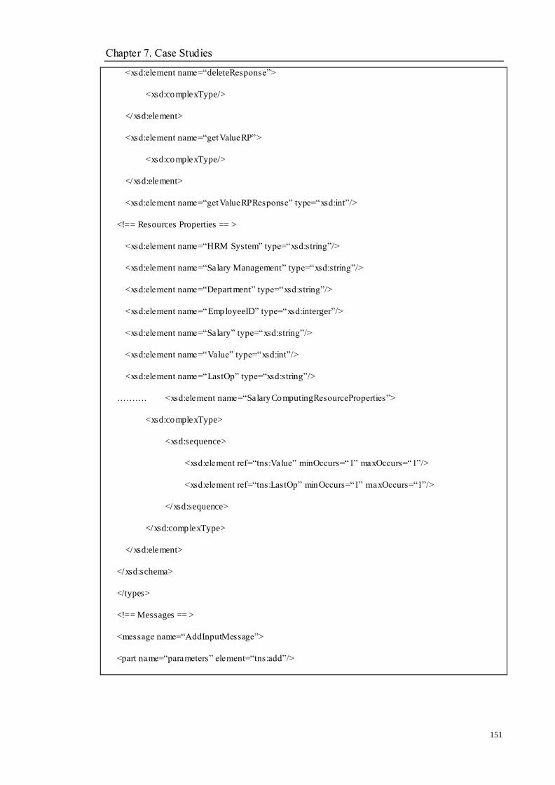
Chapter 7. Case Studies
151
<xsd:element name=―deleteResponse‖>
<xsd:complexType/>
</xsd:element>
<xsd:element name=―getValueRP‖>
<xsd:complexType/>
</xsd:element>
<xsd:element name=―getValueRPResponse‖ type=―xsd:int‖/>
<!== Resources Properties == >
<xsd:element name=―HRM System‖ type=―xsd:string‖/>
<xsd:element name=―Salary Management‖ type=―xsd:string‖/>
<xsd:element name=―Department‖ type=―xsd:string‖/>
<xsd:element name=―EmployeeID‖ type=―xsd:interger‖/>
<xsd:element name=―Salary‖ type=―xsd:string‖/>
<xsd:element name=―Value‖ type=―xsd:int‖/>
<xsd:element name=―LastOp‖ type=―xsd:string‖/>
………. <xsd:element name=―SalaryComputingResourceProperties‖>
<xsd:complexType>
<xsd:sequence>
<xsd:element ref=―tns:Value‖ minOccurs=―1‖ maxOccurs=―1‖/>
<xsd:element ref=―tns:LastOp‖ minOccurs=―1‖ maxOccurs=―1‖/>
</xsd:sequence>
</xsd:complexType>
</xsd:element>
</xsd:schema>
</types>
<!== Messages == >
<message name=―AddInputMessage‖>
<part name=―parameters‖ element=―tns:add‖/>

Chapter 7. Case Studies
152
</message>
<message name=―AddOutputMessage‖>
<part name=―parameters‖ element=―tns:addResponse‖/>
</message>
<message name=―DeletetInputMessage‖>
<part name=―parameters‖ element=―tns:delete‖/>
</message>
<message name=―DeleteOutputMessage‖>
<part name=―parameters‖ element=―tns:deleteResponse‖/>
</message>
<message name=―GetValueRPInputMessage‖>
<part name=―parameters‖ element=―tns:getValueRP‖/>
</message>
<message name=―GetValueRPOutputMessage‖>
<part name=―parameters‖ element=―tns:getValueRPResponse‖/>
</message>
<!== Porttype == >
<portType name=―SalaryComputingPortType‖
wsdlpp:extends=―wsrpw:GetResourceProperty‖
wsrp:ResourceProperties=―tns:SalaryComputingResourceProperties‖>
<operation name=―add‖>
<input message=―tns:AddInputMessage‖/>
<output message=―tns:AddOutputMessage‖/>
</operation>
<operation name=―delete‖>
<input message=―tns:DeleteInputMessage‖/>
<output message=―tns:deltetOutputMessage‖/>
</operation>

Chapter 7. Case Studies
153
<operation name=―getValueRP‖>
<input message=―tns:GetValueRPInputMessage‖/>
<output message=―tns:GetValueRPOutputMessage‖/>
</operation>
</portType>
</definit ions>
Table 7-11 WSDL Descript ion of SalaryComputing Resource Properties in XML
The wsrp:ResourceProperties is used to specify what the service properties are. The
<portType> defines the operations such as ―add‖, ―delete‖ and ―getValue‖ with all the
messages and types. All operations consist of an input and output content. With the help
of WSDL description, the service resource can be easy to access.
7.6.2 Service Implementation
The service is implemented by Java. Qualified name (QName) is a name that includ es a
name space and a local name that is used to refer to the service. The QName of the
value can be defined as:
{http://examples.org/strl/HRM/SalaryComputing service}Value, where the first part is
the namespace and the second part is the local name. A SalaryCompuingQName.java is
used as an interface class to interact conveniently. Table 7-12 shows the QName
document.
package org.strl.HRM.SalaryComputing;
import javax.xml.namespace.QName;
public interface SalaryComputingQNames
{public static final String NS = ―http://examples.org/strl/HRM/SalaryComputing service‖;
public static final QName RP_VALUE = new QName(NS, ―Value‖);
public static final QName RP_LASTOP = ne w QName(NS, ―LastOp‖);
public static final QName RESOURCE_PROPERTIES = new
QName(NS,‖SalaryComputingResourceProperties‖);

Chapter 7. Case Studies
154
}
Table 7-12 QName.java of SalaryComputing Service
While the request and response message for resource property is generated, they are
required to be wrapped in a SOAP representation for the interface interaction. Table
7-13 and 7-14 show the description.
soap:Envelope>
<soap:Header><tns:resourceID>SalaryComputing</tns:resourceI
D>
</soap:Header>
<soap:Body>
<wsrp:GetMultipleResourceProperty>
xmlns:tns= https://... >
<wsrp:ResourceProperty>
tns: EmployeeID
</wsrp:ResourceProperty>
<wsrp:ResourceProperty>
tns: Salary
</wsrp:ResourceProperty>
</wsrp:GetMult ipleResourceProperty>
</soap:Body>
</soap:Envelope>>
Table 7-13 Request Message Description
soap:Envelope>
<soap:Body>
<wsrp:GetMultipleResourcePropertyResponse>
<Employee> ―Employee‖</Empoyee>
</wsrp:GetMult ipleResourcePropertyResponse>
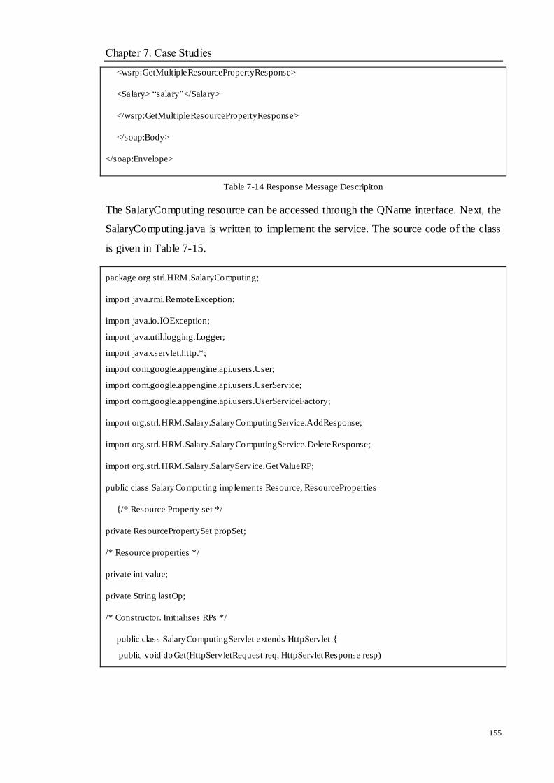
Chapter 7. Case Studies
155
<wsrp:GetMultipleResourcePropertyResponse>
<Salary> ―salary‖</Salary>
</wsrp:GetMult ipleResourcePropertyResponse>
</soap:Body>
</soap:Envelope>
Table 7-14 Response Message Descripiton
The SalaryComputing resource can be accessed through the QName interface. Next, the
SalaryComputing.java is written to implement the service. The source code of the class
is given in Table 7-15.
package org.strl.HRM.SalaryComputing;
import java.rmi.RemoteException;
import java.io.IOException;
import java.util.logging.Logger;
import javax.servlet.http.*;
import com.google.appengine.api.users.User;
import com.google.appengine.api.users.UserService;
import com.google.appengine.api.users.UserServiceFactory;
import org.strl.HRM.Salary.SalaryComputingService.AddResponse;
import org.strl.HRM.Salary.SalaryComputingService.DeleteResponse;
import org.strl.HRM.Salary.SalaryServ ice.GetValueRP;
public class SalaryComputing implements Resource, ResourceProperties
{/* Resource Property set */
private ResourcePropertySet propSet;
/* Resource properties */
private int value;
private String lastOp;
/* Constructor. Init ialises RPs */
public class SalaryComputingServlet extends HttpServlet {
public void doGet(HttpServ letRequest req, HttpServletResponse resp)
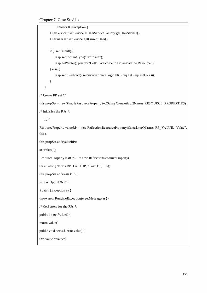
Chapter 7. Case Studies
156
throws IOExcept ion {
UserService userService = UserServiceFactory.getUserService();
User user = userService.getCurrentUser();
if (user != null) {
resp.setContentType("text/plain");
resp.getWriter().println("Hello, Welcome to Download the Resource");
} else {
resp.sendRedirect(userService.createLoginURL(req.getRequestURI()));
}
}
/* Create RP set */
this.propSet = new SimpleResourcePropertySet(SalaryComputingQNames.RESOURCE_PROPERTIES);
/* Initialise the RPs */
try {
ResourceProperty valueRP = new ReflectionResourceProperty(Calcu latorQNames.RP_VALUE, ―Value‖,
this);
this.propSet.add(valueRP);
setValue(0);
ResourceProperty lastOpRP = new ReflectionResourceProperty(
CalculatorQNames.RP_LASTOP, ―LastOp‖, this);
this.propSet.add(lastOpRP);
setLastOp(―NONE‖);
} catch (Exception e) {
throw new RuntimeException(e.getMessage());}}
/* GetSetters for the RPs */
public int getValue() {
return value;}
public void setValue(int value) {
this.value = value;}

Chapter 7. Case Studies
157
public String getLastOp() {
return lastOp;}
public void setLastOp(String lastOp) {
this.lastOp = lastOp;}
/* Remotely-accessible operations */
public AddResponse add(int a) throws RemoteException {
value += a;
lastOp = ―ADDITION‖;
return new AddResponse();}
public DelelteResponse delete(file path) throws RemoteException {
if (path.exists()) {
File[] files = path.listFiles();
for (File file : files) {
if (file.isDirectory()) {
deleteDirectory(file);
} else {
boolean delete = file .delete();
if(!delete) {
throw new RuntimeException("Could not
delete file: " + file .getAbsolutePath());
}
}
}
}
return (path.delete());
}
value -= a;
lastOp = ―DELETE‖;
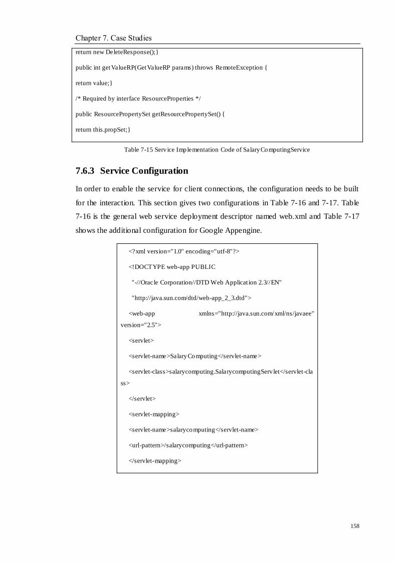
Chapter 7. Case Studies
158
return new DeleteResponse();}
public int getValueRP(GetValueRP params) throws RemoteException {
return value;}
/* Required by interface ResourceProperties */
public ResourcePropertySet getResourcePropertySet() {
return this.propSet;}
Table 7-15 Serv ice Implementation Code of SalaryComputingService
7.6.3 Service Configuration
In order to enable the service for client connections, the configuration needs to be built
for the interaction. This section gives two configurations in Table 7-16 and 7-17. Table
7-16 is the general web service deployment descriptor named web.xml and Table 7-17
shows the additional configuration for Google Appengine.
<?xml version="1.0" encoding="utf-8"?>
<!DOCTYPE web-app PUBLIC
"-//Oracle Corporation//DTD Web Applicat ion 2.3//EN"
"http://java.sun.com/dtd/web-app_2_3.dtd">
<web-app xmlns="http://java.sun.com/xml/ns/javaee"
version="2.5">
<servlet>
<servlet-name>SalaryComputing</servlet-name>
<servlet-class>salarycomputing.SalarycomputingServ let</servlet-cla
ss>
</servlet>
<servlet-mapping>
<servlet-name>salarycomputing</servlet-name>
<url-pattern>/salarycomputing</url-pattern>
</servlet-mapping>

Chapter 7. Case Studies
159
<welcome-file-list>
<welcome-file>index.html</welcome-file>
</welcome-file-list>
</web-app>
Table 7-16 Web.xml Configurat ion of SalaryComputing Service
<?xml version="1.0" encoding="utf-8"?>
<appengine-web-app
xmlns="http://appengine.google.com/ns/1.0">
<application>SalaryComputingServ ice</applicat ion>
<version>1</version>
</appengine-web-app>
Table 7-17 Appengine-web.xml of Salary Computing Service
7.6.4 Service Deployment
The deployment process for Google Appengine can be completed by Eclipse or a
command prompt. In Eclipse, the Google Plugin‘s choice ―Deploy to App Engine‖ is
easy to click on with a Google account. In the command prompt, two commands for
Windows and Mac OX or Linux:
..\appengine-java-sdk\bin\appcfg.cmd update war
../appengine-java-sdk/bin/appcfg.sh update war
Once the deployment is successful, the message will be shown in the control view.
Figure 7-10 and Figure 7-11 show the package content and deployment successful
message.
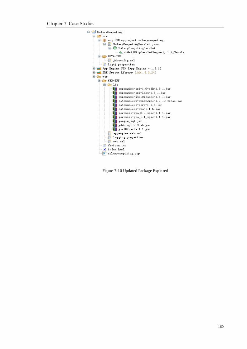
Chapter 7. Case Studies
160
Figure 7-10 Updated Package Explored
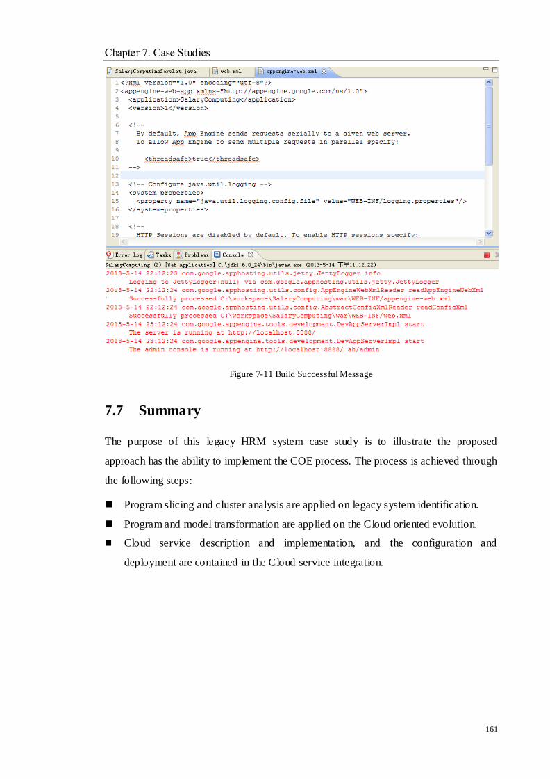
Chapter 7. Case Studies
161
Figure 7-11 Build Successful Message
7.7 Summary
The purpose of this legacy HRM system case study is to illustrate the proposed
approach has the ability to implement the COE process. The process is achieved through
the following steps:
Program slicing and cluster analysis are applied on legacy system identification.
Program and model transformation are applied on the Cloud oriented evolution.
Cloud service description and implementation, and the configuration and
deployment are contained in the Cloud service integration.

Chapter 8. Conclusions
162
Chapter 8 Conclusion and Future
Work
Objectives
_________________________________________________________________
To summarise the whole thesis
To revisit original contributions
To evaluate the research with answers to the research questions; by reviewing
the research hypotheses and the success criteria
To illustrate the limitations of the work
To outline future work
_________________________________________________________________
8.1 Summary of Thesis
The principal research question in this thesis is: ―How can a three-dimensional
dependable evolution approach based model, software functions and non-functional
features be developed in order to implement two phases of COE?‖ To answer this
question, the following work has been done.
A proposed COE approach has been given in this research, which contains three main
stages, namely, legacy service analysis and extraction, Cloud service migration and
Cloud services integration. In the stage of legacy service analysis and extraction, an
assessment framework including the features of a Cloud categories based AHP is
introduced to judge whether and which types of legacy systems are able to be chosen.
Then, combining the static and dynamic program slicing techniques with an improved
slicing algorithm is proposed to decompose the legacy code. Finally, software
clustering techniques are adopted to capture the corresponding reusable code segments.
The architect‘s view and users‘ requirements help to decide the cutting point on the
dendrogram.
Chapter 8. Conclusions
163
In the stage of Cloud service migration; there are two phases to illustrate the process.
First, PIM is abstracted from the original PSM but F and NFR do not change because
nothing is operated on the two parts. Certain required qualities for Cloud are needed to
add to the transfer process between PIM and PIMc, and program transformation is used
to support the transfer. Now, the software has been able to run in the Cloud
environment with Cloud features. Second, the evolution is considered only based on
the change of software functions which normally are to be added according to new
functional requirements. During the process of generating PSMnew, it can be believed
that software architecture is changed to reflect PSMnew being generated, which is done
by changing software architecture type or enhancing the existing architecture through
pre-defined transformation rules. The forward engineering techniques are applied to
support the generation of the new system.
In the stage of Cloud service integration, the XML represented legacy resources are
defined as stateful resources, and WSDL is used to design the resource properties and
interface. Using Java implements the service and the new service can be deployed and
integrated in the Cloud services. Finally, a prototype is described and the case study is
chosen to validate the proposed approach.
8.2 Contributions Revisiting
A novel COE approach has been proposed in Chapter 3. In this Section, the five
original contributions described in Chapter 1 will be revisited.
C1. In Chapter 3, a three-dimensional paradigm is proposed for supporting the
evolution in Figure 3-1. The solution framework is shown in Figure 3-2. Three
main stages are included in the whole process, namely, legacy service
assessment and identification, Cloud service implementation and Cloud service
integration.
C2. In Chapter 4, an assessment approach is defined for analysis, which combines
Cloud features based on an AHP technique to judge whether the selected legacy
systems are feasible to migrate to Cloud environments. The process of the
approach is presented in Figure 4-1. The improved program slicing and software
Chapter 8. Conclusions
164
cluster are described in Section 4.3.2 and Section 4.3.3.
C3. In Chapter 5, an integration model is defined, which includes the work on how
to evolve the legacy system with non-function requirements into a Cloud
environment. A series of rules about translation, abstraction and transformation
are given in Chapter 5.
C4. In Chapter 5, an architecture model is defined, which includes the work on how
to implement and handle the functional requirement change on the software
model when the systems plan evolves in the Cloud environment. Transformation
rules are proposed in Section 5.3.
C5. Chapter 6 describes the Cloud integration architecture and Chapter 8 gives the
case studies and toolsets which have been developed to illustrate the proposed
approach.
8.3 Revisiting Success Criteria
In Chapter 1, five success criteria are defined to validate the success of the proposed
research described in this thesis. This section will revisit the predefined measures of
success.
What are the mainstream kinds of software systems that can be processed by
the proposed approach?
The proposed approach is applied on the legacy components that include
procedures, modules, objects, files, etc. Each stage of the approach can deal
with the legacy system effectively.
What kinds of program and model transformation can reliably be appied on
the proposed approach?
In the stage of Cloud service implementation, abstraction and refactoring
have been used to complete the purpose that is to generate new services. A
series of rules are defined to support these techniques in Chapter 5.
How can the WSL representation of software models be applied in the
evolution process?
Chapter 8. Conclusions
165
The work process in evolution in the proposed approach is based around WSL.
The abstraction from PSM to PIM can be implemented by WSL with the
syntax and semantic representation. The transformation rules in FermaT are
able to help the evolution result be more specified.
How is the performance of this proposed approach?
Legacy systems are reused in the Cloud environment, which brings certain
advantages from business and research aspects. For business, reusing legacy
systems in Cloud can cut the cost and time for redesigning a new system. For
research, the novel approach is proposed, which can advance the traditional
software engineering techniques to fulfil the Cloud requirements and explore
the Cloud computing technologies deeply.
How about the implementation of the proposed methods, algorithms and
strategies? E.g., is it possible to develop a practical toolkit to implement and
validate the approach?
The answer is ―Yes‖. A prototype is designed with existing tool support and a
case study has been used to prove the proposed approach in Chapter 7.
8.4 Limitations
After discussing the original contributions and success criteria, the limitations of the
proposed research described in this thesis are discussed as follows:
Requirements extraction via RRF approach and requirements management via the
process management requirements model may demand manual work and become
time consuming.
The assessment stage via AHP technique may demand manual work and become
time consuming.
During the assessment stage, a great number of criteria will be discovered and
determined. Meanwhile, the Saaty scale is something which, from the view of
most architects and enterprises, may contain a few errors. The calculation for the
judgement needs to be done manually and the proposed approach cannot be a fully
Chapter 8. Conclusions
166
semi-automatic solution. If certain mistakes exist in the computing process, the
wrong decision may be caused.
The poor quality of the legacy system may affect the efficiency of the proposed
approach.
In this research, the legacy system is analysed from three aspects, namely,
software qualities, software functions, and software models. If some of them are
missing or are not represented in a standard format, the stages of identification and
evolution will be inadequate and cause cost of time, money and resources. It may
lead to the creation of some mistakes for the final result. If the legacy systems are
designed by standard programming, such as comments, document and coding
format, etc., the proposed approach will be more effective.
8.5 Future Work
Based on the discussions regarding original contributions, research questions, research
hypotheses, success criteria and limitations, these conclusions can be given. The
proposed COE approach in this thesis is a novel, effective and systematic
methodology for handling the software evolution and Cloud computing. The
supporting tool and user case have validated the proposed approach. In the COE
situation, the semi-automatic approach can bring a new attempt to think of evolution
from a three-dimensional space and improve the traditional software engineering
effectively.
The research presented in this thesis is not thefinishing point. A series of future work
can be extended based on this present work:
Based on the assessment framework discussed in Chapter 4.2, the application
criteria can be extended by adding several factors, i.e., programming language
and data completeness, which could be more correct for making the decision.
Based on the discussion of program slicing and software clustering, the
program slicing algorithm could be perfected in a class/object slice. The
bottom-up agglomerative cluster process could be improved by proposing more
correct updating in a similar method used between clusters, i.e., the weight
Chapter 8. Conclusions
167
combined method. The algorithms may not satisfy all kinds of legacy systems
and they need to be further developed.
The modified rules for translation between PIM and PSM, transformation PIM
and PIMc in Chapter 5 can be improved by adding more concrete rules to
advance and fulfil the different situations. The rules of architecture
transformation for implementing a new PSM based on new functions can add
more constraints during the design process.
The integration of Cloud services in Chapter 6 should be able to be improved
by considering the types of Cloud platforms. More issues may be discovered
and need to be solved, such as security, lifecycle management and notification.
The prototype is required to be perfected in the future and further case studies
are needed to experiment and evaluate the present work as this novel COE
approach to evolution of the said systems is still at a fairly early stage in
three-dimensional space.
References
168
References
[1] R. Al, F. Dalpiaz, P. Glorgini and E. Silva Souza, "Requirements Evolution:
from Assumptions to Reality", Enterprise, Business-Process and Information
Systems Modeling, Springer, Vol. 81, No. 1, pp. 372-382, 2011.
[2] G. Allen, K. Davis, T. Goodale, A. Hutanu, H. Kaiser, T. Kielmann, A. Merzky,
R. Reinefeld, F. Schintke, T. Schott, E. Seidel and B. Ullmer, "The Grid
Application Toolkit: Toward Generic and Easy Application Programming
Interfaces for The Grid", Proceedings of IEEE, IEEE Computer Society, Vol.
93, No. 3, pp. 534-550, 2005.
[3] R. S. Amold, "A Road Map Guide to Software Reengineering Technology",
Software reengineering (2nd ed), IEEE Computer Society Press, Los Alamitos,
California, 1994.
[4] M. Armbrust., A. Fox., R. Griffith., A. D. Joseph., R. H. Katz., A. Konwinski.,
G. Lee., D. A. Patterson., A. Rabkin., I. Stoica. and M. Zaharia., "Above the
Cloude: A Berkeley View of Cloud Computing", TechnicalReport :
UCB/EECS-2009-28, EECS Department, University of California Berkeley,
2009.
[5] D. Atkinson and W. Griswold, "The Design of Whole Program Analysis Tools",
Proceedings of the 18th international conference on Software engineering,
Washington, DC, USA, pp. 16-27, 1996.
[6] C. Bachmann, "A CASE for Reverse Engineering", Datamation, IT BUSINESS
EDGE, Vol. 34, No. 13, pp. 49-56, 1988.
[7] X. Bai, H. Yu, G. Wang, Y. Ji, M. Mannescu and L. Boloin, "Coordination in
Intelligent Grid environments", IEEE, 93, No. 3, pp. 613-630, 2005.
[8] B. Barns and T. Bollinger, "Making Reuse Cost-Effective", IEEE Software,
IEEE Computer Society, Vol. 8, No. 1, pp. 13-24, 1991.
[9] L. Bass, P. Clements and R. Kazman, Software Architecture in Practice,
References
169
Addison Wesley, UK, 1998.
[10] L. R. D. Bastos and J. F. B. Castro., "Systematic Integration between
Requirements and Architecture", Software Engineering for Multi-Agent Systems
III, Springer Berlin Heidelberg, Vol. 3390, No. 3, pp. 85-103, 2005.
[11] K. H. Bennett and V. Rajlich, "Software Maintenance and Evolution: A
Roadmap", Proceedings of the Conference on The Future of Software
Engineering, New York, USA, pp. 73-87, 2000.
[12] K. H. Bennett and V. T. Rajlich, "Software Maintenance and Evolution: A
Roadmap", Proceedings of the Conference on The Future of Software
Engineering, Ireland, pp. 73-87, 2000.
[13] K. H. Bennett, M. Ramage and M. Munro, "Decision Model for Legacy
Systems", IEEE Software, IEEE Computer Society, Vol. 146, No. 3, pp.
153-159, 1999.
[14] D. Binkley and K. Gallagher, "Program Slicing", Advances in Computers,
Academic Press, Vol. 43, No. 1, pp. 1-50, 1996.
[15] B. W. Boehm, J. R. Brown, H. Kaspar, M. Lipow, G. Macleod and M. Merritt,
Characteristics of Software Quality, Elsevier Science Ltd, North Holland, 1978.
[16] G. Booch, R. A. Maksimchuk, M. W. Engel, B. Young, J. Conallen and K. A.
Houston, Object-Oriented Analysis and Design with Applications,
Addison-Welsey, USA, 2007.
[17] P. T. Breuer, H. Haughton and K. Lano, "Reverse-Engineering COBOL via
Formal Methods", Journal of Software Maintenance and Evolution:Research
and Practice, John Wiley & Sons, Vol. 5, No. 1, pp. 13-35, 1993.
[18] M. L. Brodie and M. Stonebraker, Migrating Legacy Systems-Gateways,
Interfaces & the Incremental Approach, Morgan Kaufmann Publishers, Inc.,
San Francisco, Califormia, 1995.
[19] F. P. Brooks, "No Silver Bullet: Essence and Accidents of Software
Engineering", IEEE Computer, IEEE, Vol. 20, No. 4, pp. 10-19, 1987.
[20] R. Buyya, C. Yeo, S. Venugopal, J. Broberg and L. Brandic, "Cloud Computing
References
170
and Emerging IT Platforms: Visson, Hype and Reality for Delivering
Computing as the 5th Utility", Future Generation Computer Systems, Elsevier
Science Publishers, Vol. 25, No. pp. 599-616, 2009.
[21] C. Canfora, A. Cimitile and M. Munro, "An Improved Algorithm for Identifying
Reusable Objects in Code", Journal of Software Practice and Experiences,
Wiley, Vol. 26, No. 1, pp. 24-48, 1996.
[22] G. Canfora, A. Cimitile, A. D. Lucia and G. A. D. Lucca, "Decomposing
Legacy Programs", Journal of Systems and Software, Elsevier, Vol. 5, No. 4,
pp. 99-110, 2000.
[23] G. Canfora, A. Climitile, A. De Lucia and G. Di Lucca, "Decomposing Legacy
Systems: A First Step Towards Migrating to Client-Server Platforms", Journal
of Systems and Software, Elsevier, Vol. 54, No. 2, pp. 99-110, 2000.
[24] G. Canfora, A. R. Fasolino, G. Frattolilo and P. Tramontana, "A Wrapping
Approach for Migrating Legacy System Iinteractive Functionalities to Service
Oriented Architectures", Journal of Systems and Software, Elsevier Science Inc.,
Vol. 81, No. 4, pp. 463-480, 2008.
[25] C. K. Chang, H. Jiang, H. Ming and K. Oyama, "Situ: A Situation Theoretic
Approach to Context-Aware Service Evolution", IEEE Transcations on Service,
IEEE Press, Vol. 2, No. 3, pp. 261-275, 2009.
[26] M. A. Chauhan and M. A. Babar, "Migrating Service-Oriented Systems to
Cloud Computing: An Experience Report", Proceedings of the 2011 IEEE 4th
International Conference on Cloud Computing, Washington, DC, USA, pp.
404-411, 2011.
[27] F. Chen, "Model Driven Software Modernisation,", De Montfort University,
UK, 2007.
[28] F. Chen, S. Li and H. Yang, "Feature Analysis for Service-Oriented
Re-engineering", 12 th IEEE Asia-Pacific Software Engineering
Conference(APSEC 05), Taipei, Taiwan, pp. 201-208, 2005.
[29] L. Chen, C. Wang and W. Lau, "A Grid Middleware for Distributed Java
Computing with MPI Binding and Process Migration Supports", JOURNAL OF
COMPUTER SCIENCE AND TECHNOLOGY, Springer, Vol. 18, No. 4, pp.
References
171
505-514, 2003.
[30] L. Q. Chen, "Integrating Cloud Computing Services Using Enterprise Service
Bus (ESB)", Business and Management Research, Sciedu Press, Vol. 1, No. 1,
2012.
[31] B. H. C. Cheng and J. M. Atlee, "Research Directions in Requirements
Engineering", Future of Software Engineering, IEEE Computer Society,
Washington DC, USA, pp. 285-303, 2007.
[32] E. Chikofsky and J. Cross, "Reverse Engineering and Design Recovery: A
Taxonomy", IEEE Software, IEEE Computer Society, Vol. 7, No. 1, pp.
13-17, 1990.
[33] L. Childers, T. Disz, R. Olson, M. Papka, R. Stevens and T. Udeshi, "Access
Grid: Immersive Group to Group Collaborative Visualization", Proceedings of
4th International Immersive Protection Technology Workshop, 2000.
[34] S. Chung, J. Byang and S. Davalos, "Service-Oriented Software
Reengineering:SOSR", 40th Annual Hawaii International Conference on
Systems Sciences(HICSS 2007), pp. 172-176, 2007.
[35] CRM, "HRM System", http://www.csdn.net/,2013
[36] A. Deursen and T. Kuipers, "Identifying Objects Using Cluster and Concept
Analysis", 21th International Conference on Software Engineering, Los
Angeles, USA, pp. 246-255, 1999.
[37] R. G. Dromey, "A Model for Software Product Quality", Software Engineering,
IEEE Transactions, Vol. 21, No. 2, pp. 146-162, 1995.
[38] S. Easterbrook, J. Singer, M. Storey, and D. Damian, "Selecting Empirical
Methods for Software Engineering Research", Chapter 11 in Guide to Advanced
Empirical Software Engineering, Springer Verlag, 2008.
[39] N. A. Ernst, J. Mylopoulos and J. Wang, "Requirements Evolution and What
(Research) to Do about It", Design Requirements Engineering: A Ten-Year
Perspective, Springer, Vol. 14, No. 3, pp. 186-214, 2009.
[40] F. Fabbrni, M. Fusani, S. Gnesi and G. Lami, "Controlling Requirements
References
172
Evolution: A Formal Concept Analysis-Based Approach", IEEE International
Conference on Software Engineering Advances, Cap Esterel, French Riviera,
France, pp. 68-69, 2007.
[41] J. Ferrante, K. Ottenstein and J. Warren, "The Program Dependence Graph and
Its Use in Optimization", ACM Transactions on Programming Languages and
Systems, ACM Press, Vol. 9, No. 3, pp. 319-349, 1987.
[42] R. T. Fielding, "Architecture Styles and the Design of Network-based
Softwarew Architectures,", University of California, 2000.
[43] I. Foster, D. Berry, A. Djaoui, Grimshaw, B. Hom, H. Kishimoto, F. Maciel, A.
Savva, F. Siebenlist, R. Subramaniam, J. Treadwell, and J. Von Reich, "Open
Grid Services Architecture, Informational Document", Global Grid Forum
(GGF), 2005.
[44] K. Gallagher and J. Lyle, "Using Program Slicing in Software Maintenance",
IEEE Transactions on Software Engineering, IEEE Press, Vol. 17, No. 8, pp.
751-761, 1991.
[45] M. Galster, A. Eberiein and M. Moussavi, "System Selection of Software
Architectures Styles", IET Software, 4, No. 5, pp. 349-360, 2010.
[46] L. Gao, Y. Ding and L. Ren, "A Novel Ecological Network-Based Computation
Platform as a Grid Middleware System", International Journal of Intelligent
Systems, IOS Press, Vol. 19, No. 10, pp. 859-884, 2004.
[47] D. Garlan, R. Monroe and D. Wile, "Acme: An Architecture Decription
Interchange Language", Proceedings of CASCON 97, Toronto, Ontario, Canada,
pp. 169-183, 1997.
[48] G. Gimnich, "SOA Migration - Approaches and Experience", TechnicalReport :
30-34, IBM Software Group, SOA Advanced Technology / Enterprise
Integration Solutions, 2013.
[49] N. Gold and K. H. Bennett, "Hypothesis-Based Concept Assignment in
Software Maintenance", IEEE Software, IEEE Press, Vol. 149, No. 4, pp.
103-110, 2002.
[50] Google Developers, "Google App Engine",
References
173
https://developers.google.com/appengine/,2013
[51] R. B. Grady, Practical Software Metrics for Project Management and Process
Improvement: Prentice-Hall, Inc. Upper Saddle River, NJ, USA, 1992.
[52] P. Gruenbacher, A. Egyed and N. Medvidovic, "Reconcilling Software
Requirements and Architectures with Intermediate Models", Software and
System Modelling, Springer-Verlag, Vol. 3, No. 3, pp. 235-253, 2004.
[53] Y. Guo, M. Ghanem and R. Han, "Does the Cloud need new algorithms? An
introduction to elastic algorithms", IEEE 4th International Conference of Cloud
Computing Technology and Science, Taibei, pp. 66-73, 2012.
[54] J. Han, M. Kamber and J. Pei, Data Mining: Concepts and Techniques, Morgan
Kaufmann, Canada, 2011.
[55] S. Hanna and M. Munro, "An Approach for Specification-Based Test Case
Generation for Web Services", IEEE/ACS International Conference on
Computer Systems and Applications, Amiman, pp. 16-23, 2007.
[56] S. D. P. Harris and J. E. Dobson, "The Change and Evolution of Requirements
as A Challenge to The Practice of Software Engineering", IEEE International
Symposium on Requirements Engineering, San Diego, CA, U.S.A, pp. 266-272,
1993.
[57] J. S. Henumann, "Requirements Discovery for Legacy Systems",
TechnicalReport : IBM Software Group, 2003.
[58] C. Hofmeister, R. Nord and D. Soni, Applied Software Architecture, Addison
Wesley, Canada, 1999.
[59] S. Horwitz, T. Reps and D. Binkley, "Interprocedural Slicing Using Dependence
Graphs", ACM Transactions on Programming Languages and Systems, ACM
Press, Vol. 12, No. 1, pp. 26-60, 1990.
[60] S. Horwitz, T. Reps and D. Binkley, "Interprocedural Slicing Using Dependence
Graphs", ACM SIGPLAN Notices, ACM Press, Vol. 39, No. 4, pp. 232-243,
2004.
[61] A. K. Hosseini, D. Greenwood and I. Sommerville, "Cloud Migration: A Case

References
174
Study of Migrating an Enterprise IT system to Iaas", IEEE 3rd International
Conference on Cloud Computing, Miami, USA, pp. 450-457, 2010.
[62] N. Howarth, Abstract Syntax Tree Design, APPM.1551, APM Ltd., Cambridge,
UK, 1995.
[63] IBM, "Service",
http://researcher.watson.ibm.com/researcher/view_project.php?id=1230,2013
[64] IBM Software Group, "Managing Legacy Integration with IBM Rational
Software", TechnicalReport : TP902, IBM, USA, 2003.
[65] IEEE Standard Definition of Software Engineering, "IEEE Standard Collection:
Software Engineering", IEEE Inc, 1997.
[66] ISO, "Systems and software engineering--Systems and software Quality
Requirements and Evaluation (SQuaRE) - System and software quality models",
TechnicalReport : International Organisation of Standardisation, 2011.
[67] ISO Standard Definition of Software Engineering, "Software Engineering -
Software Life Cycle Processes - Maintenance", ISO/IEC, 2006.
[68] ISO/IEC Group, "FCD 9126-1.2: Information Technology - Software Product
Quality, Part 1: Quality Model", TechnicalReport : 9126-1-2, ISO/IEC, 1998.
[69] Y. Jiang and E. Stroulia, "Towards Reengineering Web Sites to Web-Services
Provider", Proceedings of 8th European Conference on Software Maintenance
and Reengineering (CSMR), Tampere, Finland, pp. 296-305, 2004.
[70] P. Kacsuk, A. Goyeneche, T. Delaitre, T. Kiss, Z. Farkas and T. Boczko,
"High-Level Grid Application Environment to Use Legacy Codes as OGSA
Grid Services", 5th IEEE/ACM International Workshop on Grid Computing,
Washington, DC, USA, pp. 428-435, 2004.
[71] E. Karl, Software Requirements, Redmond: Microsoft Press, USA, 2003.
[72] J. Kim, S. Park and V. Sugumaran, "A Framework of Domain Requirements
Analysis and Modeling Architecture in Software Product Lines", Journal of
Systems and Software, Elsevier Science Inc., Vol. 81, No. 1, pp. 37-55,
2008.
References
175
[73] R. Koschke and T. Eisenbarth, "A Framework for Experimental Evaluation of
Clustering Techniques", Proceedings of 8th International Workshop on
Program Comprehension, Limerick, Ireland, pp. 201-210, 2000.
[74] P. J. M. Laarhoven, V and W. Pedrycz, "A Fuzzy Extension of Saaty's Priority
theory", Fuzzy Sets and Systems, Elsevier, Vol. 11, No. pp. 229-241, 1983.
[75] R. Land, "A Brief Survey of Software Architecture", TechnicalReport :
MDH-MRTC-57/2002-1-SE, Malardalen Real-Time Research Centre,
Malardalen University, 2002.
[76] L. D. Larsen and M. J. Harrold, "Slicing Object-Oriented Software",
Proceedings of the 18th International Conference on Software Engineering,
Berlin, Germany, pp. 495-505, 1996.
[77] J. Lavery, B. Boldyreff, B. Ling and C. Allison, "Modeling the Evolution of
Legacy Systems to Web-based System", Journal of Software Maintenance and
Evolution:Research and Practice-Special issue: Web site evolution, John Wiley
& Sons, Inc., Vol. 16, No. 2, pp. 5-30, 2004.
[78] M. M. Lehman, "Laws of Software Evolution Revisited", EWSPT '96
Proceedings of the 5th European Workshop on Software Process Technology,
London, pp. 108-124, 1996.
[79] M. M. Lehman and L. A. Belady, Program evolution: Processes of Software
Change, Academic Press Professional, Inc., San Diego, CA, USA, 1985.
[80] M. M. Lehman, J. F. Ramil and D. E. Perry, "On Evidence Supporting the
FEAST Hypothesis and the Laws of Software Evolution", METRICS '98
Proceedings of the 5th International Symposium on Software Metrics, Bethesda,
MD, USA, pp. 84-88, 1998.
[81] M. M. Lehman, J. F. Ramil and G. Kahen, "Evolution as a Noun and Evolution
as a Verb", SOCE 2000 Workshop on Software and Organisation Co-evolution,
London, 2000.
[82] M. M. Lehman, J. F. Ramil and U. Sandler, "An Approach to Modelling
Long-Term Growth Trends in Software Systems", ICSM '01 Proceedings of the
IEEE International Conference on Software Maintenance (ICSM'01),
Washington, DC, USA, pp. 219-228, 2001.

References
176
[83] LevelA Software, "Software Life Cycle Models",
http://www.levela.com/software_life_cycles_swdoc.htm,2013
[84] H. Li, H. Guo, F. Chen, H. Yang and Y. S. Yang, "Using Ontology to Generate
Test Cases for GUI Testing", Journal of Computer Applications in Technology,
InderScience, Vol. 42, No. 2/3, pp. 213-224, 2011.
[85] J. Li and H. Yang, "Towards Developing Grid Middleware for Software
Evolution", (Position Paper) IEEE International Software Technology and
Engineering Practice Conference (STEP), Hungary, 2005.
[86] S. Li, F. Chen and H. Yang, "Using Feature-Oriented Analysis to Recover
Legacy Software Design for Software Evolution", Proceedings of Software
Engineering and Knowledge Engineering, Taibei, Taiwan, pp. 336-341, 2005.
[87] B. P. Lientz and E. B. Swanson, Software Maintenance Management, A Study of
the Maintenance of Computer Application Software in 487 Data Processing
Organizations, Addison-Wesley, Reading, MA, 1980.
[88] C. Lindig and G. Snelting, "Assessing Modular Structure of Legacy Code Based
on Mathematical Concept Analysis", Proceedings of the 19th International
Conference on Software Engineering, Boston, MA, USA, pp. 349-359, 1997.
[89] M. Lormans, "Monitoring Requirements Evolution Using Views", Proceedings
of the 11th European Conference on Software Maintenance and Reengineering,
Washington, DC, USA, pp. 349-352, 2007.
[90] A. D. Lucia, A. R. Fasolino and E. Pompella, "A Decisional Framework for
Legacy System Management", Florence, Italy, pp. 642-651, 2001.
[91] A. D. Lucia, R. Francese, G. Scanniello and G. Tortoral, "Developing Legacy
System Migration Methods and Tools for Technology Transfer", Journal of
Software Practice and Experiences, John Wiley & Sons, Inc., Vol. 38, No. 13,
pp. 1333-1364, 2008.
[92] J. Lv, X. X. Ma, X. P. Tao and F. Hu. H. Xu, "Research and Progress of
Internetware", Science in China Series.F: Information Sciences, Springer, Vol.
36, No. 10, pp. 1037-1080, 2006.
[93] A. Maarek, R. Fagin, I. Shaul and D. Pelleg, "Ephemera Document Clustering
References
177
for Web Applications", TechnicalReport : RJ10186, IBM Research, 2000.
[94] E. Marks and B. Lozano, Executive's Guide to Cloud Computing, John Wiley &
Sons, USA, 2010.
[95] J. A. McCall, P. K. Richards and G. F. Walters, "Factors in Software Quality",
TechnicalReport : RADC-TR-79-97, Rome Air Development Center-Air Forece
Systems, New York, 1977.
[96] H. Mei and X. Z. Liu, "Internetware: An Emerging Software Paradigm for
Internet Computing", JOURNAL OF COMPUTER SCIENCE AND
TECHNOLOGY, Springer, Vol. 26, No. 4, pp. 588-599, 2011.
[97] M. Mock, D. Atkinson and S. Eggers, "Program Slicing with Dynamic Points-to
Sets", IEEE Transactions on Software Engineering, IEEE Press, Vol. 31, No. 8,
pp. 657-678, 2005.
[98] MOF, "XMI", http://www.omg.org/spec/XMI/,2013
[99] P. Mohagheghi and V. Dehlen, "Where Is the Proof? - A Review of Experiences
from Applying MDE in Industry", 4th European Conference on Model Driven
Architecture Foundations and Applications (EDMDA-FA'08), Berlin, Germany,
pp. 432-443, 2008.
[100] A. Monaco, "A View Inside the Cloud",
http://theinstitute.ieee.org/technology-focus/technology-topic/a-view-inside-the-
cloud,2013
[101] MSDN, "ESB SOA Frameworks",
http://www.ibm.com/developerworks/web/library/wa-soaesb/,2013
[102] B. Navneet and Rai, Strategic Decision Making: Applying the Analytic
Hierarchy Process, Springer-Verlag, London, 2004.
[103] NIST, "Cloud Definition",
http://csrc.nist.gov/groups/SNS/cloud-computing/,2013
[104] F. Ohata, K. Hirose, M. Fujii and K. Inoue, "A Slicing Method for
Object-Oriented Programs Using Lightweight Dynamic Information",
Proceedings of the Eighth Asia-Pacific on Software Engineering Conference,

References
178
Washington, DC, USA, pp. 273-280, 2001.
[105] J. Rasquinha and M. Z. Hussain, "HR on cloud has a promising future: Experts",
http://www.deccanherald.com/content/146025/hr-cloud-has-promising-future.ht
ml,2013
[106] F. Ricca and P. Tonella, "Using Clustering to Support the Migration from Static
to Dynamic Web Pages", 11th IEEE International Workshop on Program
Comprehension, Portland, Oregon, USA, pp. 207-216, 2003.
[107] R. Richardson, D. Lawless, J. Bisbal, B. Wu, J. Grimson and V. Wade, "A
Survey of Research into Legacy System Migration", TechnicalReport :
TCD-CS-1997-01, Computer Science Department, Trinity College Dublin,
Dublin, 1997.
[108] B. Rochwerger, Breitgand, E. Levy, A. Galis, K. Naign, I. M. Llorente, R.
Montero, Y. Wolfsthal, E. Elmroth, J. Caceres, M. Ben-Yehuda, W. Emmerich
and F. Galan, "The Reservoir Model and Architecture for Open Federated Cloud
Computing", IBM Journal of Research and Development, 53, No. 4, pp.
535-545, 2009.
[109] H. Romesburg, Cluster Analysis for Researchers, LuLu Press, USA, 2004.
[110] M. Ruth and B. Dana, Functional Requirements and Use Cases,
www.bredemeyer.com,2013
[111] T. L. Saaty, "Decision Making with the Analytic Hierarchy Process",
International Journal of Services Sciences, InderScience, Vol. 1, No. 1, pp.
83-98, 2008.
[112] T. L. Saaty, "The Analytic Hierachy Process", TechnicalReport : New York:
McGraw Hill International, 1980.
[113] R. Schwanke, "An Intelligent Tool for Re-engineering Software Modularity",
Proceedings of 13th International Conference on Software Engineering, USA,
pp. 83-92, 1991.
[114] R. Seacord, D. Plakosh and G. Lewis, Modernizing Legacy Systems: Software
Technologies, Addison Welsey Press, Boston, MA, USA, 2003.
References
179
[115] M. Shaw and C. P. Clements, "A Field Guide to Boxology: Preliminary
Classification of Architectural Styles for Software Systems", Proc.21st
Int.Computer Software and Applications, Washington, DC, pp. 6-13, 1997.
[116] H. Sneed, "Object Oriented COBOL Recycling", 3rd IEEE Working Conference
of Reverse Engineering, USA, pp. 169-178, 1996.
[117] H. Sneed and S. Sneed, "Creating Web Services from Legacy Host Programs",
5th IEEE International Workshop on Web Site Evolution, Amsterdam, The
Netherlands, pp. 59-65, 2003.
[118] H. M. Sneed and E. Nyary, "Downsizing Large Application Programs", Journal
of Software Maintenance:Research and Practice, John Wiley & Sons, Vol. 6,
No. 5, pp. 105-116, 1994.
[119] I. Sommerville, Software Engineering, Addison-Wesley, USA, 2010.
[120] T. Sorenson, A Method of Establishing Groups of Equal Amplitude in Plant
Sociology based on Similarity of Species Content, Kobenhavn, Munksgaard,
Denmark, 1948.
[121] N. H. Sulaiman, T. Mara, S. Alam and M. Daud, "A Jaccard-Based Similarity
Measure for Soft Sets", IEEE Symposium on Humanities, Science and
Engineering Research, Kuala Lumpur, pp. 659-663, 2012.
[122] G. Taenzer, "AGG: A Graph transformation Environment for Modeling and
Validation of Software", Applications of Graph Transformations with Industrial
Relevance, Springer, 2004.
[123] C. Tan, K. Liu, L. Sun and C. Spence, "An Evaluation Framework for Migrating
Application to the Cloud: Software as a Service", Proceedings of 2nd
International Conference on Logistics, Informatics and Service Science,
Springer, Vol. 2, No. 1, pp. 967-972, 2012.
[124] P. Thiran and J. Hainaut, "Wrapper Development for Legacy Data Reuse", 8th
IEEE Working Conference on Reverse Engineering, Germany, pp. 198-207,
2001.
[125] S. R. Tilley and D. B. Smith, S. R. Tilley and D. B. Smith, "Perspectives on
Legacy System Reengineering", http://www.sei.cmu.edu/, 1996,2013
References
180
[126] F. Tip, "A Survey of Program Slicing Techniques", Journal of Programming
Languages, CompSciNet, Vol. 3, No. 3, pp. 121-189, 1995.
[127] P. Tonella, F. Ricca, E. Pianata and C. Girardi, "Using Keyword Extraction for
Web Site Clustering", 5th IEEE International Workshop on Web Site Evolution
(WSE), Amsterdam, The Netherlands, pp. 41-48, 2003.
[128] V. Tzerpos and R. Holt, "Mojo: A Distance Metric for Software Clustering",
Proceedings of 6th Working Conference on Reverse Engineering, Atlanta, pp.
187-193, 1999.
[129] A. Umar and A. Zordan, "Reengineering for Service Oriented Architectures: A
Strategic Decision Model for Integration versus Migration", Journal of Systems
and Software, Elsevier Science Inc., Vol. 82, No. 3, pp. 448-462, 2008.
[130] C. Vecchiola, X. Chu and R. Buyya, "Aneka: A Software Platform for .Net
based Cloud Computing", High Performance Computing Workshop, Cettraro,
Italy, pp. 267-295, 2008.
[131] W3C, "WSDL", http://www.w3schools.com/wsdl/,2013
[132] W3C, "XML Schema", http://www.w3.org/TR/xmlschema-formal/,2013
[133] W3schools, "SOAP", http://www.w3schools.com/soap/,2013
[134] J. Ward, "Hierarchical Gropuing to Optimize an Objective Function", Journal of
the American Statistical Association, ASA Online, Vol. 58, No. 201, pp.
236-244, 1963.
[135] M. Ward, "The FermaT Assembler Re-engineering Workbench", Proceedings
of International Conference on Software Maintenance, Florence, Italy, pp.
659-662, 2001.
[136] M. Ward, "The Formal Transformation Approach to Source Code Analysis and
Manipulation", IEEE International Working Conference on Source Code
Analysis and Manipulation, Florence, Italy, pp. 187-195, 2001.
[137] M. Ward, "Slicing the SCAM Mug: A Case Study in Semantic Slicing.", IEEE
International Working Conference on Source Code Analysis and Manipulation,
Amsterdam, The Netherlands, pp. 88-97, 2003.

References
181
[138] M. Ward and K. H. Bennett, "Formal Methods to Aid the Evolution of
Software", International Journal of Software Engineering and Knowledge
Engineering,Special Issue on "Software Evolution" , World Scientific, Vol. 5,
No. 1, pp. 25-47, 1995.
[139] M. Ward and H. Zedan, "MetaWSL and Meta-Transformations in the FemaT
Transformation System", Proceedings of 29th Annual International Computer
Software and Applications Conference, Edinburgh, Scotland, UK, pp. 233-238,
2005.
[140] M. Ward, H. Zedan and T. Hardcastle, "Legacy Assembler Reengineering and
Migration", Proceedings of the International Conference on Cognitive
Modelling, Pittsburgh, Pennsylvania, USA, pp. 157-166, 2004.
[141] M. Ward, H. Zedan and T. Hardcastle, "Conditioned Semantic Slicing via
Abstraction and Refinement in FermaT", Proceedings of 9th European
Conference on Software Maintenance and Reengineering, Manchester, UK, pp.
178-187, 2005.
[142] M. Weiser, "Program Slicing", IEEE Transcations on Software Engineering,
IEEE Press, Vol. 10, No. 4, pp. 439-449, 1984.
[143] T. Wiggerts, "Using Clustering Algorithms in Legacy Systems
Remodularization", Proceedings of 4th Working Conference on Reverse
Engineering, Limerick Ireland, pp. 275-279, 1997.
[144] D. S. Wile, "Architecture style-based calculi for non-functional properties",
Proceedings of 18th IEEE International Conference Automated Software,
Montreal, Que., Canada, pp. 299-303, 2003.
[145] F. Q. Yang, H. Mei, J. Lv and Z. Jin, "Some Discussion on the Development of
Software Technology", ACTA ELECTRONICA SINICA, Oriprobe Information
Services, Inc., Vol. 30, No. 12, pp. 1901-1906, 2002.
[146] H. Yang and M. Ward, Successful Evolution of Software Systems, Artech House,
London, 2003.
[147] H. Yang and S. Zheng, "Software Evolution for Moving into and Moving within
Internentware", International Journal of Software and Informatics, 7, No. 1,
pp. 41-61, 2013.
References
182
[148] H. Yang, X. D. Liu and H. Zedan, "Abstraction: A Key Notion for Reverse
Engineering in a System Reengineering Approach", Journal of Software
Maintenance, Wiley, Vol. 12, No. 4, pp. 197-228, 2000.
[149] H. Yang, S. Zheng and W.C.C.Chu, "Linking Functions and Qualitiy Attributes
for Software Evolution", Proceedings of 19th Asia-Pacific Software
Engineering Conference, Taibei, Taiwan, pp. 250-269, 2012.
[150] X. Yang, "QoS-Oriented Service Computing: Bring SOA into C Environment",
Design Approaches to Emerging Software Systems: Principles, Methodology
and Tools, IGI Global, 2011.
[151] X. Yang, B. Nasser, M. Surridge and S. Middleton, "A business-oriented Cloud
federation model for real-time applications", Future Generation Computer
Systems, Elsevier, Vol. 28, No. 8, pp. 1158-1167, 2012.
[152] A. Yeh, D. Harris and H. Reubenstein, "Recovering Abstract Data Type and
Object Instances from A Conventional Procedural Language", Proceedings of
Working Conference on Reverse Engineering, Kingston, Canada, pp. 227-236,
1995.
[153] C. You, M. H. Zhou, Z. Xiao and H. Mei, "Towards a dynamic and adaptable
application server", 33rd Annual IEEE International Computer Software and
Applications Conference, Seattle, Washington, USA, pp. 427-434, 2009.
[154] Z. Zhang, R. Liu and H. Yang, "Service Identification and Packaging in Service
Oriented Reengineering", Proceedings of the 7th International Conference on
Software Engineering and Knowledge Engineering, Redwood City, San
Francisco, pp. 241-249, 2005.
[155] J. Zhao, "Dynamic Slicing of Object-Oriented Programs", TechnicalReport :
SE-98-119, Information Processing Society of Japan, 1998.
[156] S. Zheng and H. Yang, "An Approach to Supporting Architecture Evolution in
Internetware", Proceedings of the Fourth Asia-Pacific Symposium on
Internetware, Qingdao, China, pp. 31-40, 2012.
[157] S. Zheng, D. L. Jing, F. Chen and H. Yang, "Cloud Computing Platform for
Software Evolution", Univeristy of Birmingham, UK, 2010.

References
183
[158] S. Zheng, H. Yang, L. Liu and J. M. Wang, "Software Evolution in Setting of
Internetware", The Third Asa-Pacific Symposium on Internetware, Internetware
2011, Nan Ning, Guang Xi, China, 2011.
[159] S. Zheng, H. Yang, Z. Ma and L. Liu, "Understanding Software Reengineering
Requirements for Cloud Computing", 19th Ieee International Requirements
Engineering Conference, Trento, Italy, 2011.
[160] S. Zschaler, "Formal Specification of Non-Functional Properties of
Component-based Software Systems", Software and System Modelling,
Spring-Verlag, Vol. 9, No. 2, pp. 161-201, 2010.

Appendix A: Partial WSL Representation of HRM System and CML Construction of
MonthWage
184
Appendix A: Partial WSL
Representation of HRM System and
CML Construction of MonthWage
This is an automated software system for Human Resource Management that can handle
the employees and departments in the organisations. It is not a complete HRM software
like those implemented in the companies, but still it can manage the information of
employees and departments at the backend. It has a nice graphical layout written in Java
Language with over 3000 lines‘ code. The following is the selected parts of source code
of WSL representation in HRM system.
Class MonthWageRecord {
serialVersionUID;
jlabe1;
jlabel1;
jContentPane;
jScro llPane
jTable
};
proc MonthwageRecord() {
!xp super();
!xp init ialize();
};
proc init ialize () {
!xp setContentPane(getJcontentPane());
!xp setTitle("Dep Month Wage Record");

Appendix A: Partial WSL Representation of HRM System and CML Construction of
MonthWage
185
!xp setBounds(new Rectangle(0, 0, 1024, 700));
!xp setResizable(false);
};
proc getJContentPane() {
if(jContentPane<>0)then
strul := "HRMS.mdb";
!xp getConnecton(strl);
jLabel := new JLabel();
!xp setBounds(new Rectangle(22, 511, 149, 15));
!xp setText("");
!xp setVisib le(false);
jLabel1 := new JLabel();
!xp setBounds(new Rectangle(22, 511, 149, 15));
!xp setText("");
!xp setVisib le(false);
jContentPane := new JPanel();
!xp setLayout(null);
!xp add(jLabel, null);
!xp add(getJScrollPane(), null);
!xp ResultSet (rs);
if (rs := "Select * From temp")
rs++
jLabel := getString("num");
jLabel11 := getString("nam")
!xp catch (Exception)
else rs := "select * from wagerecord where t im='" +
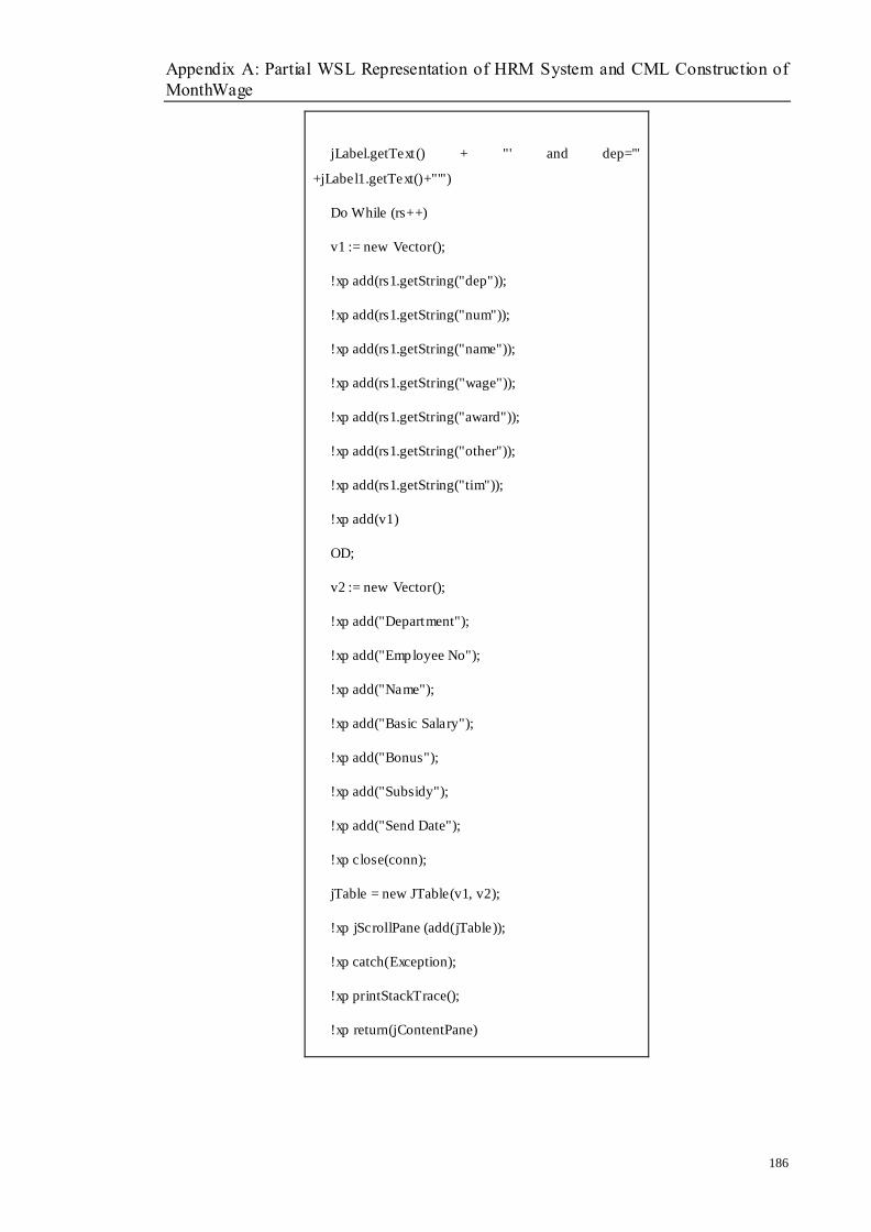
Appendix A: Partial WSL Representation of HRM System and CML Construction of
MonthWage
186
jLabel.getText() + "' and dep='"
+jLabel1.getText()+"'")
Do While (rs++)
v1 := new Vector();
!xp add(rs1.getString("dep"));
!xp add(rs1.getString("num"));
!xp add(rs1.getString("name"));
!xp add(rs1.getString("wage"));
!xp add(rs1.getString("award"));
!xp add(rs1.getString("other"));
!xp add(rs1.getString("tim"));
!xp add(v1)
OD;
v2 := new Vector();
!xp add("Department");
!xp add("Employee No");
!xp add("Name");
!xp add("Basic Salary");
!xp add("Bonus");
!xp add("Subsidy");
!xp add("Send Date");
!xp close(conn);
jTable = new JTable(v1, v2);
!xp jScrollPane (add(jTable));
!xp catch(Exception);
!xp printStackTrace();
!xp return(jContentPane)
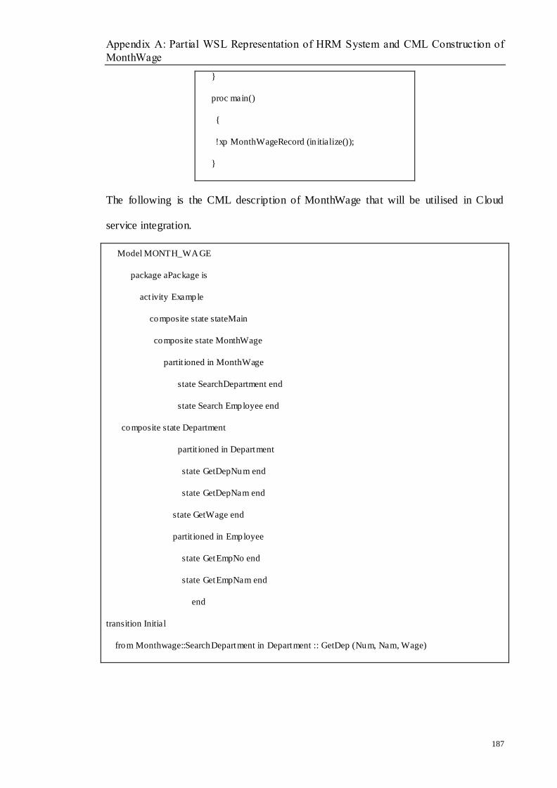
Appendix A: Partial WSL Representation of HRM System and CML Construction of
MonthWage
187
}
proc main()
{
!xp MonthWageRecord (in itialize());
}
The following is the CML description of MonthWage that will be utilised in Cloud
service integration.
Model MONTH_WAGE
package aPackage is
act ivity Example
composite state stateMain
composite state MonthWage
partit ioned in MonthWage
state SearchDepartment end
state Search Employee end
composite state Department
partit ioned in Department
state GetDepNum end
state GetDepNam end
state GetWage end
partit ioned in Employee
state GetEmpNo end
state GetEmpNam end
end
transition Initial
from Monthwage::SearchDepartment in Department :: GetDep (Num, Nam, Wage)
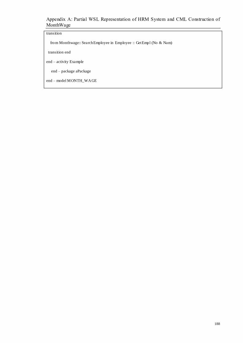
Appendix A: Partial WSL Representation of HRM System and CML Construction of
MonthWage
188
transition
from Monthwage:: SearchEmployee in Employee :: GetEmpl (No & Nam)
transition end
end – activity Example
end – package aPackage
end – model MONTH_WAGE
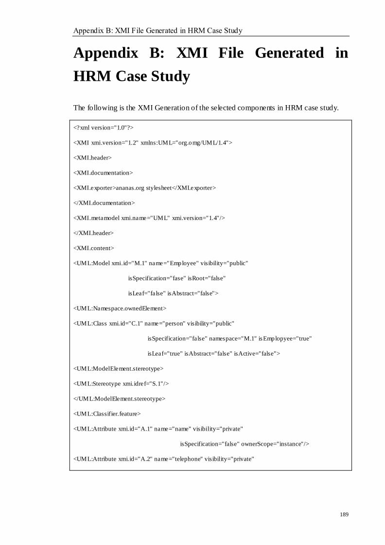
Appendix B: XMI File Generated in HRM Case Study
189
Appendix B: XMI File Generated in
HRM Case Study
The following is the XMI Generation of the selected components in HRM case study.
<?xml version="1.0"?>
<XMI xmi.version="1.2" xmlns:UML="org.omg/UML/1.4">
<XMI.header>
<XMI.documentation>
<XMI.exporter>ananas.org stylesheet</XMI.exporter>
</XMI.documentation>
<XMI.metamodel xmi.name="UML" xmi.version="1.4"/>
</XMI.header>
<XMI.content>
<UML:Model xmi.id="M.1" name="Employee" visibility="public"
isSpecification="fase" isRoot="false"
isLeaf="false" isAbstract="false">
<UML:Namespace.ownedElement>
<UML:Class xmi.id="C.1" name="person" visibility="public"
isSpecification="false" namespace="M.1" isEmplopyee="true"
isLeaf="true" isAbstract="false" isActive="false">
<UML:ModelElement.stereotype>
<UML:Stereotype xmi.idref="S.1"/>
</UML:ModelElement.stereotype>
<UML:Classifier.feature>
<UML:Attribute xmi.id="A.1" name="name" visibility="private"
isSpecification="false" ownerScope="instance"/>
<UML:Attribute xmi.id="A.2" name="telephone" visibility="private"
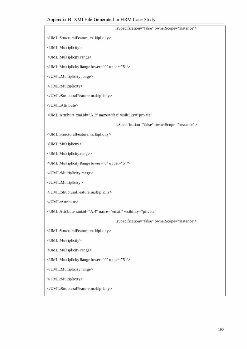
Appendix B: XMI File Generated in HRM Case Study
190
isSpecification="false" ownerScope="instance">
<UML:StructuralFeature.multiplicity>
<UML:Mult iplicity>
<UML:Mult iplicity.range>
<UML:Mult iplicityRange lower="0" upper="5"/>
</UML:Multip licity.range>
</UML:Multip licity>
</UML:StructuralFeature.mult iplicity>
</UML:Attribute>
<UML:Attribute xmi.id="A.3" name="fax" visib ility="private"
isSpecification="false" ownerScope="instance">
<UML:StructuralFeature.multiplicity>
<UML:Mult iplicity>
<UML:Mult iplicity.range>
<UML:Mult iplicityRange lower="0" upper="5"/>
</UML:Multip licity.range>
</UML:Multip licity>
</UML:StructuralFeature.mult iplicity>
</UML:Attribute>
<UML:Attribute xmi.id="A.4" name="email" visibility="private"
isSpecification="false" ownerScope="instance">
<UML:StructuralFeature.multiplicity>
<UML:Mult iplicity>
<UML:Mult iplicity.range>
<UML:Mult iplicityRange lower="0" upper="5"/>
</UML:Multip licity.range>
</UML:Multip licity>
</UML:StructuralFeature.mult iplicity>

Appendix B: XMI File Generated in HRM Case Study
191
</UML:Attribute>
</UML:Classifier.feature>
</UML:Class>
<UML:Class xmi.id="C.2" name="Department" visibility="public"
isSpecification="false" namespace="M.1" isRoot="true"
isLeaf="true" isAbstract="false" isActive="false">
<UML:Classifier.feature>
<UML:Attribute xmi.id="A.5" name="name" visibility="private"
isSpecification="false" ownerScope="instance"/>
<UML:Attribute xmi.id="A.6" name="address" visibility="private"
isSpecification="false" ownerScope="instance"/>
<UML:Attribute xmi.id="A.7" na me="telephone" visibility="private"
isSpecification="false" ownerScope="instance"/>
<UML:Attribute xmi.id="A.8" name="type" visibility="private"
isSpecification="false" ownerScope="instance"/>
<UML:Attribute xmi.id="A.9" name="wage" visibility="private"
isSpecification="false" ownerScope="instance"/>
<UML:Attribute xmi.id="A.10" name="depID" visib ility="private"
isSpecification="false" ownerScope="instance"/>
</UML:Classifier.feature>
</UML:Class>
<UML:Class xmi.id="C.3" name="Salary" visib ility="public"
isSpecification="false" namespace="M.1" isRoot="true"
isLeaf="true" isAbstract="false" isActive="false">
<UML:Classifier.feature>
<UML:Attribute xmi.id="A.11" name="tit le" visibility="private"
isSpecification="false" ownerScope="instance"/>
<UML:Attribute xmi.id="A.12" name="organization" visibility="private"
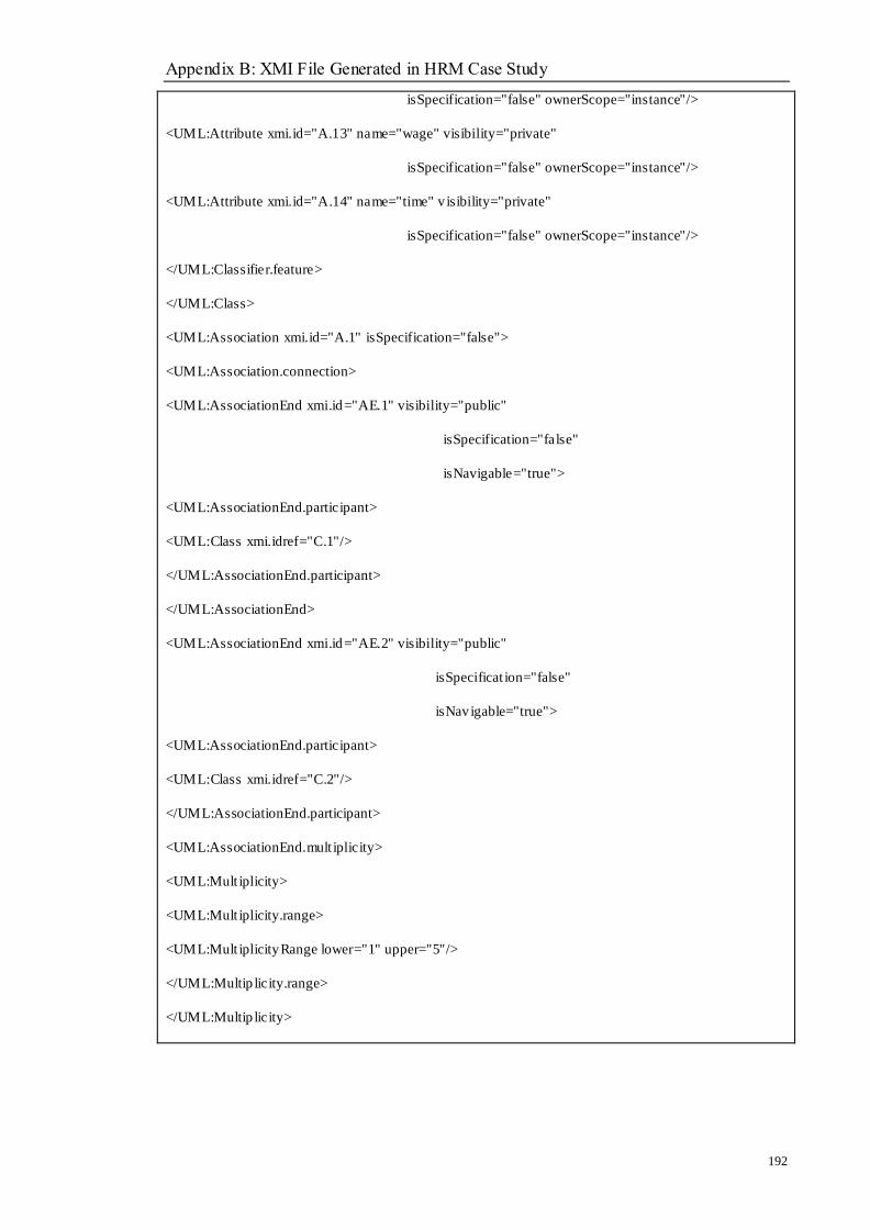
Appendix B: XMI File Generated in HRM Case Study
192
isSpecification="false" ownerScope="instance"/>
<UML:Attribute xmi.id="A.13" name="wage" visibility="private"
isSpecification="false" ownerScope="instance"/>
<UML:Attribute xmi.id="A.14" name="time" v isibility="private"
isSpecification="false" ownerScope="instance"/>
</UML:Classifier.feature>
</UML:Class>
<UML:Association xmi.id="A.1" isSpecification="false">
<UML:Association.connection>
<UML:AssociationEnd xmi.id="AE.1" visibility="public"
isSpecification="false"
isNavigable="true">
<UML:AssociationEnd.participant>
<UML:Class xmi.idref="C.1"/>
</UML:AssociationEnd.participant>
</UML:AssociationEnd>
<UML:AssociationEnd xmi.id="AE.2" visibility="public"
isSpecificat ion="false"
isNavigable="true">
<UML:AssociationEnd.participant>
<UML:Class xmi.idref="C.2"/>
</UML:AssociationEnd.participant>
<UML:AssociationEnd.mult iplicity>
<UML:Mult iplicity>
<UML:Mult iplicity.range>
<UML:Mult iplicityRange lower="1" upper="5"/>
</UML:Multip licity.range>
</UML:Multip licity>

Appendix B: XMI File Generated in HRM Case Study
193
</UML:AssociationEnd.mult iplicity>
</UML:AssociationEnd>
</UML:Association.connection>
</UML:Association>
<UML:Association xmi.id="A.2" isSpecification="false">
<UML:Association.connection>
<UML:AssociationEnd xmi.id="AE.3" visibility="public"
isSpecification="false"
isNavigable="true">
<UML:AssociationEnd.participant>
<UML:Class xmi.idref="C.1"/>
</UML:AssociationEnd.participant>
</UML:AssociationEnd>
<UML:AssociationEnd xmi.id="AE.4" visibility="public"
isSpecificat ion="false"
isNavigable="true">
<UML:AssociationEnd.participant>
<UML:Class xmi.idref="C.3"/>
</UML:AssociationEnd.participant>
</UML:AssociationEnd>
</UML:Association.connection>
</UML:Association>
<UML:Association.connection>
<UML:AssociationEnd xmi.id="AE.4" visibility="public"
isSpecification="false"
isNavigable="true">
<UML:AssociationEnd.participant>
<UML:Class xmi.idref="C.1"/>
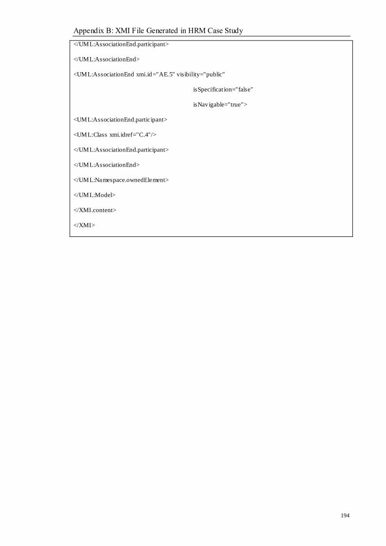
Appendix B: XMI File Generated in HRM Case Study
194
</UML:AssociationEnd.participant>
</UML:AssociationEnd>
<UML:AssociationEnd xmi.id="AE.5" visibility="public"
isSpecificat ion="false"
isNavigable="true">
<UML:AssociationEnd.participant>
<UML:Class xmi.idref="C.4"/>
</UML:AssociationEnd.participant>
</UML:AssociationEnd>
</UML:Namespace.ownedElement>
</UML:Model>
</XMI.content>
</XMI>

Appendix C: Syntax for SADL in CML
195
Appendix C: Syntax for SADL in CML
The following is the syntax definition of style architecture descripition language in
CML model.
SADL::= SADLMODEL<EOF>
SADLMODEL::= SADLList StyleDef StyelLinkDef
SADLList::= <SADLTypeList> "CML_Spec" SADLTypeListDef
SADLTypeList::= (<SADLType> SADLTypeName <is> State Connector Role)*
SADLTypeName::= <IDENTIFIER>
State::= " CML_Spec"
Connector::= "CML_Spec"
Role::=<Action> (ActionList)? ";" <Event> (EventList)? ";" <Constraints>
(ConstraintsList)?";"
ActionList::= " CML_Spec"
ConstraintsList::= " CML_Spec"
EventList::= "CML_Spec"
StyleDef::= <Style_instances><are> ":" (StyleName <Instantiates> StyleLinkDef";")*
StyleName::= <IDENTIFIER>
Sty leLinkDef ::= Link("," Link)*
Link ::= One_OneLink
::= Many_OneLink
::= One_ManyLink
One_OneLink ::= Prov ideService "->" RequestService
Many_OneLink::= ProvideServ iceList "->" RequestService
One_ManyLink ::= ProvideService "->" RequestServiceList
ProvideServ iceList ::= (ProvideService)*
RequestServiceList ::= (RequestService)*
Appendix C: Syntax for SADL in CML
196
ProvideService ::= <IDENTIFIER>
RequestService ::= <IDENTIFIER>
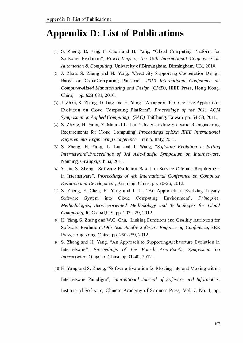
Appendix D: List of Publications
197
Appendix D: List of Publications
[1] S. Zheng, D. Jing, F. Chen and H. Yang, ―Cloud Computing Platform for
Software Evolution‖, Proceedings of the 16th International Conference on
Automation & Computing, University of Birmingham, Birmingham, UK, 2010.
[2] J. Zhou, S. Zheng and H. Yang, ―Creativity Supporting Cooperative Design
Based on CloudComputing Platform‖, 2010 International Conference on
Computer-Aided Manufacturing and Design (CMD), IEEE Press, Hong Kong,
China, pp. 628-631, 2010.
[3] J. Zhou, S. Zheng, D. Jing and H. Yang, ―An approach of Creative Application
Evolution on Cloud Computing Platform‖, Proceedings of the 2011 ACM
Symposium on Applied Computing (SAC), TaiChung, Taiwan, pp. 54-58, 2011.
[4] S. Zheng, H. Yang, Z. Ma and L. Liu, ―Understanding Software Reengineering
Requirements for Cloud Computing‖,Proceedings of19th IEEE International
Requirements Engineering Conference, Trento, Italy, 2011.
[5] S. Zheng, H. Yang, L. Liu and J. Wang, ―Software Evolution in Setting
Internetware‖,Proceedings of 3rd Asia-Pacific Symposium on Internetware,
Nanning, Guangxi, China, 2011.
[6] Y. Jia, S. Zheng, ―Software Evolution Based on Service-Oriented Requirement
in Internetware‖, Proceedings of 4th International Conference on Computer
Research and Development, Kunming, China, pp. 20-26, 2012.
[7] S. Zheng, F. Chen, H. Yang and J. Li, ―An Approach to Evolving Legacy
Software System into Cloud Computing Environment‖, Principles,
Methodologies, Service-oriented Methodology and Technologies for Cloud
Computing, IG Global,U.S, pp. 207-229, 2012.
[8] H. Yang, S. Zheng and W.C. Chu, "Linking Functions and Qualitiy Attributes for
Software Evolution",19th Asia-Pacific Software Engineering Conference,IEEE
Press,Hong Kong, China, pp. 250-259, 2012.
[9] S. Zheng and H. Yang, ―An Approach to SupportingArchitecture Evolution in
Internetware‖, Proceedings of the Fourth Asia-Pacific Symposium on
Internetware, Qingdao, China, pp 31-40, 2012.
[10] H. Yang and S. Zheng, ―Software Evolution for Moving into and Moving within
Internetware Paradigm‖, International Journal of Software and Informatics,
Institute of Software, Chinese Academy of Sciences Press, Vol. 7, No. 1, pp.
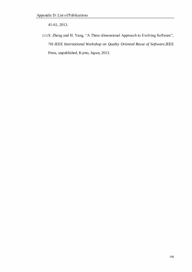
Appendix D: List of Publications
198
41-61, 2013.
[11] S. Zheng and H. Yang, ―A Three-dimensional Approach to Evolving Software‖,
7th IEEE International Workshop on Quality Oriented Reuse of Software,IEEE
Press, unpublished, Kyoto, Japan, 2013.