An approach to distributed building modeling on the basis of versions and changes
14
An approach to distributed building modeling on the basis of versions and changes Christian Koch a,⇑ , Berthold Firmenich b,1 a Akademischer Rat, Institute for Computational Engineering, Ruhr-Universität Bochum, Universitätstraße 150, 44801 Bochum, Germany b Managing Director, CADEMIA-Consult GmbH, Am Lotzenwald 58, 65719 Hofheim am Taunus, Germany article info Article history: Received 20 April 2010 Received in revised form 29 November 2010 Accepted 5 December 2010 Available online 5 January 2011 Keywords: Collaboration Versioning Change management Object-oriented modeling Building information modeling Diff and merge abstract Actors involved in the computer-supported design process work together towards a common goal – the design of a building. Current collaboration approaches often focus on versioned and distributed building models, which describe virtual building states on the basis of the object-oriented method. State changes (for example moving a wall or modifying its material) remain unconsidered and lead to inconsistency problems when exchanging, comparing and merging versioned building models. This paper presents a new modeling approach that combines existing state-oriented descriptions of a virtual building with additional change-oriented information by means of design steps denoted as modeling operations. A new language is defined for the formal description of modeling operations. These operations establish a standardized processing interface for existing building models, can represent design intents, enhance current models with change semantics and add to the consistency of these models. Moreover, this paper presents new concepts for intra-domain collaboration and model management that overcome current limitations when exchanging, comparing and merging versioned building models. The pilot implementa- tion and some project scenarios in industry verify that current design processes can benefit in principle from combined state-oriented and change-oriented building information. Ó 2010 Elsevier Ltd. All rights reserved. 1. Introduction The collaborative building design process is characterized by its iterative and distributed nature, requiring information sharing and data exchange among the actors involved. The complexity of spe- cialized design tasks has led to a broad range of data models and software tools in civil and building engineering. Hence, interoper- ability of design software and adequate management of distributed building information is a major requirement for successful collab- oration [1–3]. Current collaboration approaches usually focus on the integra- tion of building design generated in incompatible design software through standardized data structures and file formats. The most fa- mous building model standard is the Industry Foundation Classes (IFC) and the associated physical file format STEP [4,5]. These kinds of models mainly represent virtual building states as intermediate design results by means of the object-oriented method. In these state-oriented models, design steps and model changes remain unconsidered, resulting in known collaboration deficiencies such as information loss [6,7] and lack of design intentions [8] when exchanging building data as well as insufficient comparison tools and poor merge functionality when joining design revisions and alternatives [9,10]. This paper presents a new modeling approach denoted as pro- cessing-oriented modeling, which complements existing state-ori- ented descriptions of virtual buildings with additional change- oriented information by means of modeling operations (for exam- ple moving a wall, or modifying its thickness and material). The proposed model therefore contains both design states and design changes in order to describe the design process as a procedure of processing or editing a building model (analogous to information processing). In order to be independent of frequently changing technologies, the model is formally described by set theory and relational algebra. Since changes are part of the model, they are automatically recorded during the actual design process within a software tool. For this purpose a new operative modeling language is defined and formally described. Based on this new model and language, concepts for distributed, intra-domain collaboration and model management are introduced. As a result, it is concluded that the presented modeling opera- tions establish a processing interface for building models. Adding change-based information to existing building models enables them to represent and store design intentions, which in turn are advantageous when comparing and merging different versions of a building model. In contrast to state-based approaches it can be determined not only what has been changed, but also how model objects have been manipulated. The pilot implementation verifies that processing-oriented models can be implemented 1474-0346/$ - see front matter Ó 2010 Elsevier Ltd. All rights reserved. doi:10.1016/j.aei.2010.12.001 ⇑ Corresponding author. Tel.: +49 234 32 26174. E-mail addresses: [email protected] (C. Koch), [email protected] (B. Firmenich). 1 Tel.: +49 6198 5933911. Advanced Engineering Informatics 25 (2011) 297–310 Contents lists available at ScienceDirect Advanced Engineering Informatics journal homepage: www.elsevier.com/locate/aei
-
Upload
christian-koch -
Category
Documents
-
view
212 -
download
1
Transcript of An approach to distributed building modeling on the basis of versions and changes
Advanced Engineering Informatics 25 (2011) 297–310
Contents lists available at ScienceDirect
Advanced Engineering Informatics
journal homepage: www.elsevier .com/ locate/ae i
An approach to distributed building modeling on the basis of versions and changes
Christian Koch a,⇑, Berthold Firmenich b,1
a Akademischer Rat, Institute for Computational Engineering, Ruhr-Universität Bochum, Universitätstraße 150, 44801 Bochum, Germanyb Managing Director, CADEMIA-Consult GmbH, Am Lotzenwald 58, 65719 Hofheim am Taunus, Germany
a r t i c l e i n f o
Article history:Received 20 April 2010Received in revised form 29 November 2010Accepted 5 December 2010Available online 5 January 2011
Keywords:CollaborationVersioningChange managementObject-oriented modelingBuilding information modelingDiff and merge
1474-0346/$ - see front matter � 2010 Elsevier Ltd. Adoi:10.1016/j.aei.2010.12.001
⇑ Corresponding author. Tel.: +49 234 32 26174.E-mail addresses: [email protected] (C. Koch
(B. Firmenich).1 Tel.: +49 6198 5933911.
a b s t r a c t
Actors involved in the computer-supported design process work together towards a common goal – thedesign of a building. Current collaboration approaches often focus on versioned and distributed buildingmodels, which describe virtual building states on the basis of the object-oriented method. State changes(for example moving a wall or modifying its material) remain unconsidered and lead to inconsistencyproblems when exchanging, comparing and merging versioned building models. This paper presents anew modeling approach that combines existing state-oriented descriptions of a virtual building withadditional change-oriented information by means of design steps denoted as modeling operations. Anew language is defined for the formal description of modeling operations. These operations establisha standardized processing interface for existing building models, can represent design intents, enhancecurrent models with change semantics and add to the consistency of these models. Moreover, this paperpresents new concepts for intra-domain collaboration and model management that overcome currentlimitations when exchanging, comparing and merging versioned building models. The pilot implementa-tion and some project scenarios in industry verify that current design processes can benefit in principlefrom combined state-oriented and change-oriented building information.
� 2010 Elsevier Ltd. All rights reserved.
1. Introduction
The collaborative building design process is characterized by itsiterative and distributed nature, requiring information sharing anddata exchange among the actors involved. The complexity of spe-cialized design tasks has led to a broad range of data models andsoftware tools in civil and building engineering. Hence, interoper-ability of design software and adequate management of distributedbuilding information is a major requirement for successful collab-oration [1–3].
Current collaboration approaches usually focus on the integra-tion of building design generated in incompatible design softwarethrough standardized data structures and file formats. The most fa-mous building model standard is the Industry Foundation Classes(IFC) and the associated physical file format STEP [4,5]. These kindsof models mainly represent virtual building states as intermediatedesign results by means of the object-oriented method. In thesestate-oriented models, design steps and model changes remainunconsidered, resulting in known collaboration deficiencies suchas information loss [6,7] and lack of design intentions [8] whenexchanging building data as well as insufficient comparison tools
ll rights reserved.
and poor merge functionality when joining design revisions andalternatives [9,10].
This paper presents a new modeling approach denoted as pro-cessing-oriented modeling, which complements existing state-ori-ented descriptions of virtual buildings with additional change-oriented information by means of modeling operations (for exam-ple moving a wall, or modifying its thickness and material). Theproposed model therefore contains both design states and designchanges in order to describe the design process as a procedure ofprocessing or editing a building model (analogous to informationprocessing). In order to be independent of frequently changingtechnologies, the model is formally described by set theory andrelational algebra. Since changes are part of the model, they areautomatically recorded during the actual design process within asoftware tool. For this purpose a new operative modeling languageis defined and formally described. Based on this new model andlanguage, concepts for distributed, intra-domain collaborationand model management are introduced.
As a result, it is concluded that the presented modeling opera-tions establish a processing interface for building models. Addingchange-based information to existing building models enablesthem to represent and store design intentions, which in turn areadvantageous when comparing and merging different versions ofa building model. In contrast to state-based approaches it can bedetermined not only what has been changed, but also how modelobjects have been manipulated. The pilot implementation verifiesthat processing-oriented models can be implemented
298 C. Koch, B. Firmenich / Advanced Engineering Informatics 25 (2011) 297–310
conveniently, reusing existing methods, models and tools. The out-come of project scenarios in industry reveals that our approach isapplicable in principle and has a good potential to succeed,although several challenges and problems still remain unresolved.
2. Background
2.1. Object-oriented building models
Building information is usually modeled on the basis of the Ob-ject-Oriented Method (OOM). Elements of a virtual building are ab-stracted as objects. The state of an object is defined by itsattributes. Attributes can either be single values (for example thewidth of a wall) or references to other associated objects (forexample the material of a wall). Thus, a building model B is a(structured) set of model objects
B :¼ fbjb is a model objectg:
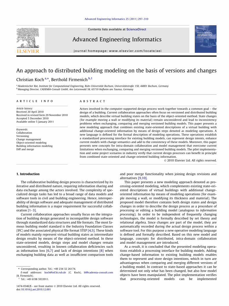
Fig. 1 illustrates a simple object-oriented building model B = {x,y,z}consisting of a wall x, a load y and an opening z. The structure be-tween model objects is represented by reference arrows, but is ne-glected in following discussions. This simplified example is reusedin the subsequent sections of his paper.
Building designers often use several software tools to edit theobject-oriented building model. These software tools implementobjects methods (for example edit the width or the material ofwall) in order to change the building state. Object methods de-scribe the behavior and functionality of single building objects.Among others, data encapsulation is a major principle in OOM inorder to ensure object consistency [11]. In data encapsulation, ob-ject attributes are protected from direct access, usually by declar-ing them private, and they must be changed by object methods(Fig. 2). Although OOM unifies object states (attributes) and objectbehavior (methods), most available building models only representbuilding states; model changes usually remain unconsidered[9,12]. The only known area where change-oriented informationis part of the modeling approach is solid modeling. Solid modelingis a consistent set of principles for mathematical modeling ofthree-dimensional solids [13]. Solids can be represented by hybridparametric models that store both the solid state (Boundary Repre-sentation, B-Rep) and the solid history in terms of operative con-struction trees (Constructive Solid Geometry, CSG). This kind ofmodels can be found in software tools like Pro/ENGINEER, Solid-Works and GenerativeComponents. However, change-orientedinformation is only related to building geometry and does not con-sider semantic information on building elements, materials, rela-tions, etc.
Fig. 1. A simplified object-oriented building model B.
Fig. 2. The object-oriented principle of data encapsulation.
2.2. Model management and collaboration
The collaborative building design process is characterized byits distributed and iterative nature. The actors involved can workin different offices around the world using different design tools.Often they find an appropriate partial solution not until a day oreven a week of iterative work. The appropriate management ofdistributed building information is a major concern in Construc-tion IT [3,14,15]. In order to meet building design requirements,several model management and collaboration concepts are infocus of current research. This paper addresses concepts likeversioning, exchanging, comparing and merging buildingmodels.
2.2.1. Model versioningIn order to ensure the consistency of distributed models and to
support model history retracing (to find out, say, in which se-quence objects have been changed), building models have to beversioned [14,15]. In general, it is distinguished between state(ver-sion)-oriented and change-oriented versioning approaches [16].However, in Construction IT version-oriented approaches aremainly considered [17,18]. The version-oriented approach focuseson the states of a building introducing a version model. Within thispaper we use the terms version and state synonymously. An objectversion is defined as a specific object state. A model version Bi isdescribed by a structured set of object versions, respectively.
Bi :¼ fbjb is a model object version in model state ig
Within the version-oriented approach single model states and theirrelations are considered. With the set V of model versions and thesuccessor relation it Es between the versions, the version graph Gs
(B) of a model B is
GSðBÞ :¼ ðV ; ESÞ
with
ES :¼ fðv i;v jÞ 2 V � V jv j is the successor version of v ig:
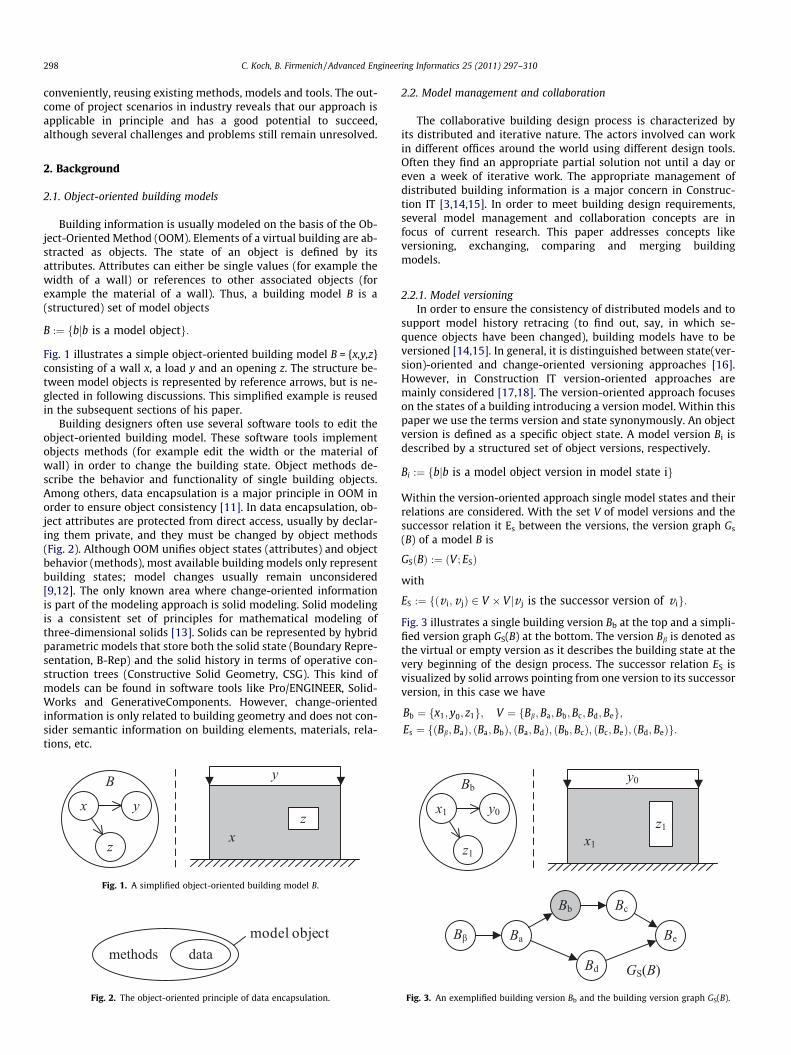
Fig. 3 illustrates a single building version Bb at the top and a simpli-fied version graph GS(B) at the bottom. The version Bb is denoted asthe virtual or empty version as it describes the building state at thevery beginning of the design process. The successor relation ES isvisualized by solid arrows pointing from one version to its successorversion, in this case we have
Bb ¼ fx1; y0; z1g; V ¼ fBb;Ba;Bb;Bc;Bd;Beg;Es ¼ fðBb;BaÞ; ðBa;BbÞ; ðBa;BdÞ; ðBb;BcÞ; ðBc;BeÞ; ðBd;BeÞg:
Fig. 3. An exemplified building version Bb and the building version graph GS(B).
C. Koch, B. Firmenich / Advanced Engineering Informatics 25 (2011) 297–310 299
In order to distinguish revisions and variants in a version graphGS(B), the transitive closure H of the successor relation ES[19] is con-sidered as
HðESÞ :¼ fðv i; vkÞ2 V � V j a path exists from version v i to version vkg:
If there is a path in the version graph from version vi to version vk,then vk is denoted as a revision of vi, otherwise vk is a variant of vi,
vk is a revision of v i : () ðv i; vkÞ 2 HðESÞ;vk is a variant of v i : () ðv i;vkÞ R HðESÞ:
For example, according to the version graph in Fig. 3, Bc is a revisionof Bb, but also a variant of Bd.
Within the parallel and iterative design process several buildingversions are generated. Each version may contain a significant partof the overall design solution. In order to integrate partial solu-tions, model versions (both revisions and variants) have to bemerged. The version graph GS(B) allows models to merges in away that it stores information about which versions are result ofa merge procedure, and which versions have been merged. Accord-ing to the version graph presented in Fig. 3, the versions Bc and Bd
are merged into version Be.Since building models are usually stored in documents, Elec-
tronic Document Management (EDM) and Project Data Manage-ment (PDM) systems are used to keep track of the model versionhistory [20–22]. These systems are limited to storing documenthistories linearly, they cannot handle document variants andtherefore do not sufficiently support the collaboration process[23]. Instead of versioning a building models as a whole, Katz[14], Firmenich [15] and Miles et al. [18] have proposed modelingsingle objects versions. A model version is then composed of astructured set of object versions and both model revisions andvariants are supported. Weise [24] has presented a combinedstate- and change-based approach of object versioning for changemanagement. As a result of a model version comparison, modeldifferences are determined on object level in order to support thedocumentation, assessment and adjustment of design steps.
In the area of software engineering, version models for SoftwareConfiguration Management (SCM) have been proposed [16]. Con-radi and Westfechtel [16] introduce a uniform version model thatcombines state-based and change-based versioning of software ob-jects. Applying this strategy to digital building models, the authorsof this paper propose a versioning approach that also combinesstate-based and change-based information to support distributedbuilding design.
2.2.2. Model exchangeBuilding models have been standardized in order to be able to
exchange building information between heterogeneous designtools. The Industry Foundation Classes (IFC) [4,25] are the most fa-mous standard. The IFC are a neutral, open and object-orienteddata model developed by the International Alliance for Interopera-bility (buildingSMART) to facilitate interoperability in the building
Fig. 4. Accumulating information loss when sequentially
and construction industry. An IFC building model represents a par-ticular state of the designed building (a version) and is usuallystored a STEP file, which can be exchanged directly between twosoftware tools, or versioned and shared via EDM and PDM systems.Lately, IFC models have been distributed via IFC Model Servers thatallow partial model access [4,26]. However, the IFC are designed asa building life-cycle data model for information exchange pur-poses. The result is a very complex data structure [5], which iscapable of storing a huge amount of building related information,but is not intended as a native application model. Design tools,on the other hand, implement their own native building models,which are intentionally optimized for processing (editing) pur-poses in order to support specific design functionalities and per-form the actual design actions. Hence, IFC building models haveto be transformed into native application models [3,5], which inev-itably results in an accumulating loss of information [6,7]. Firme-nich [6] has described the loss of information using informationsets. Fig. 4 illustrates the accumulating loss of design information.After sequentially transforming the building model versions be-tween native (BiK, i = a,b; K = X,Y,Z) and standard (Si, i = a,b) repre-sentations, the final loss of information O in application Z can beformulated as the union.
OZ ¼ ðBaX n SaÞ [ ðSa n BaYÞ [ ðBbY n SbÞ [ ðSb n BbZÞ:
Unlike version-oriented standards, Choi et al. [27] and Munet al. [28] have proposed a history-based parametric approach forexchanging change-oriented models. Their main idea is to trans-form native CAD macro files, which represent the native commandhistory, into a standard macro file that is shared between differentparametric CAD systems. Following this idea, Kim et al. [8], Prattet al. [29], and Pratt and Kim [30] present a hybrid approach forthe standardized exchange of parameterized feature-based CADmodels. They propose to describe and exchange an integratedmodel on the basis of both the procedural design history (change)and the explicit design result (state). Pratt and Kim [30] identifythe possibility of storing and exchanging design intents to be a sig-nificant advantage over version-oriented approaches. Althoughtheir work has become standardized in ISO 10303 (STEP) Parts55, 111 and 112 [31–33], it does not go beyond the exchange ofgeometrical and topological information and therefore still lackssemantic building information as well as model comparison andmerge procedures. However, the basic idea of modeling both de-sign states and design changes is pursued by the authors in this pa-per, since parametric CAD tools, for example SolidWorks, play animportant role in building design.
2.2.3. Model comparison and mergeDuring the creative design process engineers want to work in
privacy and not to be disturbed by frequent model changes fromoutside sources. The current practice in distributed building designis an optimistic approach of long-duration transactions ignoringobject locking [14,15]. In other words, the synchronization of dif-ferent model versions has to take place after a ‘long’ period of pri-vate and separated work, rather than after each single change. This
exchanging model states according to Firmenich [5].
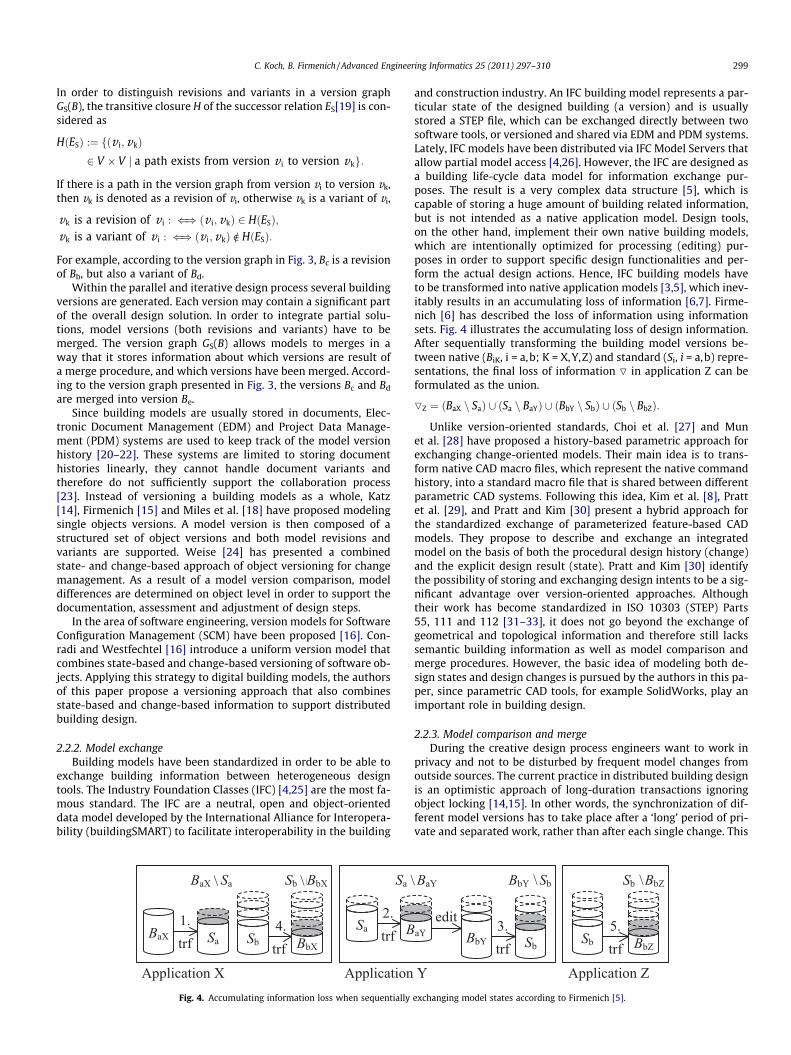
Fig. 5. The result and the sequence of moves in a chess game (V. Kramnik, V. Anand,WCC 2008 (3), Bonn 2008/10/17, Result: 0-1).
300 C. Koch, B. Firmenich / Advanced Engineering Informatics 25 (2011) 297–310
approach, of course, could lead to semantically inconsistent anddivergent model states that have to be compared and merged [34].
In order to emphasize the advantage of the comparison andmerge procedure proposed by the authors, the terms differenceand change have to be defined. The difference between two objectversions only indicates if the two objects states are identical or not,whereas the change between two object versions refers to the ac-tual modifications. For example, we assume that the object statesare presented by the values 2 and 6, respectively. Comparing theinitial state 2 and the resulting state 6 only yields a difference(2 – 6), while the actual change (or modification) is not observablesince it could be, for example, +4 or *3.
Generic EDM or PDM systems cannot support the comparisonand the merge of divergent document versions because the docu-ment content and semantics are simply not known to them[22,23]. Managed documents are treated as ‘‘black boxes’’ [23].For this reason, compare (diff) and merge functionality has to beimplemented in building design tools that already deal with build-ing semantics. For example, the software Vico Doc Set Managersupports the identification of differences in a set of DWG or PDFconstruction drawings and marks added, removed, modified andunchanged objects [4]. Since DWG and PDF files do not supportglobally unique object identification within the document’s lifecy-cle, the comparison results could have errors if an object identifierchanges over time [10]. Another example of current model com-parison tools is the software Solibri Model Checker that supportsbuilding model versions in IFC format, namely STEP files. The pro-cedure is based on a model comparison ruleset and the result is alist of objects that have been added, removed or modified. In caseof object modifications, the approach can only identify that objectshave been modified (differences), but not how they have beenchanged (changes). According to our definition above, the SolibriModel Checker is able to compare model versions up to differencedetection, actual changes cannot be identified. In addition, bothsoftware tools mentioned above do not support model versionmerge.
Central model repositories that can interpret the model content,such as the IFC Model Server Technology, allow for partial modelaccess [4,26]. First, a part of the building model is checked out(splitting), subsequently it is edited using a building design tooland finally it is re-integrated into the main parent model. The re-integration process is sometimes called a merge process. However,if there are technical or semantic conflicts between the parentmodel and the checked-out sub-models, the model server mustnot resolve them automatically because the designer is still incharge of the overall design solution and should base decisionson his/her knowledge, experiences and, of course, intentions.Moreover, since design functionality is needed to resolve designconflicts (adding, modifying and removing objects), the actualmerge process has to take place within a design tool. Analogousto the well-established merge procedure in software development(joining two versions of a text file), the merge result can then besubmitted to the central repository [10].
In general, the current diff and merge approaches describedabove are based on model and object states and thus require read-ing and even writing access to object attributes, which are usuallydeclared private (see Section 2.1). Hence, these approaches strictlyviolate the object-oriented principle of data encapsulation (Fig. 2)and can cause model inconsistency problems. Therefore, theauthors consider these approaches to be insufficient [12].
2.3. Problem statement
In order to motivate the need to integrate change-orientedinformation with existing version-oriented modeling approachestwo examples are presented below.
The first example deals with the game of chess. The game modelconsists of a board, 16 white pieces and 16 black pieces and rulesdefining the moves and capturing of pieces. The state of the gamingprocess can be described by the positions of all pieces on the board.At the end of a game only a few pieces still stand on the chess-board. While the result of the game is visible as a state, the gameprocess cannot be derived anymore. People interested in chessare not satisfied only knowing the result of the game. They wantto retrace every single move and identify strategies. For that rea-son, in addition to a figure showing the game result, the sequenceof moves is printed in magazines using a standardized notation(Fig. 5). Thus, not only the game result as a state (positions ofpieces) but also the game history as a change (moves of pieces)is presented.
The second example concerns solid modeling. Solid modelinggenerally distinguishes between two basic modeling approaches[13]. While a Boundary-Representation (B-Rep) model describesthe geometry and the topology of the solid’s surface as a state, a so-lid in a Constructive Solid Geometry (CSG) model is represented byan operative construction tree as a change history or sequence.With regard to the iterative design process, a CSG model to someextent reflects the working procedure of a designer or engineer.As illustrated in Fig. 6 (foreground), the final solid model in thisexample is designed as the union of two wall solids and the subse-quent subtraction of an opening solid. The B-Rep description of asolid (Fig. 6, background) is very complex and, at least for a humanbeing, incomprehensible. In contrast, its CSG representation in theform of modeling operations is compact, comprehensible andmeaningful. The B-Rep model, on the other hand, is very importantwithin the design process, for example when visualizing and eval-uating the solid. This supports the conclusion that both approachesare useful, and could be advantageously combined, when designinga solid.
These two simple examples reveal the advantages of a com-bined modeling approach. Besides the description of the result asa state, the history as a change process is provided in the model.Applied to building modeling this means: additional informationabout the change history and available state-oriented buildinginformation can together form a holistic building design model.Modeling operations enable the description of change semanticsand thereby allow for the representation of design intents. Themodification of building models by the designer is usually basedon a sequence of design steps or actions. According to commonsoftware design patterns, each design step is mostly representedby an internal command object [35], which already provideschange information. This means, recording change-oriented
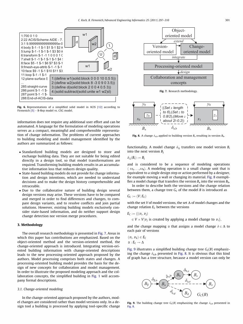
Fig. 8. A change da,b applied to building version Ba resulting in version Bb.
Fig. 9. The building change tree GC(B) emphasizing the change da,b presented inFig. 8.
Fig. 6. Representations of a simplified solid model in ACIS [12] according toFirmenich [5] – B-Rep model vs. CSG model.
Fig. 7. Research methodology.
C. Koch, B. Firmenich / Advanced Engineering Informatics 25 (2011) 297–310 301
information does not require any additional user effort and can beautomated. A language for the formulation of modeling operationsserves as a compact, meaningful and comprehensible representa-tion of change information. The problems of current approachesto building modeling and model management identified by theauthors are summarized as follows:
� Standardized building models are designed to store andexchange building data. They are not suitable for being editeddirectly in a design tool, so that model transformations arerequired. Transforming building models results in an accumula-tive information loss that reduces design quality.� State-based building models do not provide for change informa-
tion and design intentions, which are needed to understanddecisions and to make the design history comprehensible andretraceable.� Due to the collaborative nature of building design several
design versions may arise. These versions have to be comparedand merged in order to find differences and changes, to com-pare design variants, and to resolve conflicts and join partialsolutions. However, existing building models exclusively con-sider state-based information, and do neither support designchange detection nor version merge procedures.
3. Methodology
The overall research methodology is presented in Fig. 7. Areas inwhich this paper has contributions are emphasized. Based on theobject-oriented method and the version-oriented method, thechange-oriented approach is introduced. Integrating version-ori-ented building information with change-oriented descriptionsleads to the new processing-oriented approach proposed by theauthors. Model processing comprises both states and changes. Aprocessing-oriented building model provides the basis for the de-sign of new concepts for collaboration and model management.In order to illustrate the proposed modeling approach and the col-laboration concepts, the simplified building in Fig. 1 will accom-pany formal descriptions.
3.1. Change-oriented modeling
In the change-oriented approach proposed by the authors, mod-el changes are considered rather than model versions only. In a de-sign tool a building is processed by applying tool-specific change
functionality. A model change di,j transfers one model version Bi
into the next version Bj
di;jðBiÞ :¼ Bj
and is considered to be a sequence of modeling operationsh xi, . . . ,xki. A modeling operation is a small change unit that isequivalent to a single design step or action performed by a designer,for example moving a wall or changing its material. Fig. 8 exempli-fies a model change that transfers the version Ba into the version Bb.
In order to describe both the versions and the change relationbetween them, a change tree GC of the model B is introduced as
GC :¼ ðV ; ECÞ
with the set V of model versions, the set D of model changes and thechange relation EC between the versions
EC :¼ fðv i;v jÞ2 V � V jv j is created by applying a model change to v ig;
and the change mapping a that assigns a model change d 2 D toeach pair of versions
ðv i;vkÞ 2 EC
a : EC ! D
Fig. 9 illustrates a simplified building change tree GC(B) emphasiz-ing the change da,b presented in Fig. 8. It is obvious that this kindof graph has a tree structure, because a model version can only be
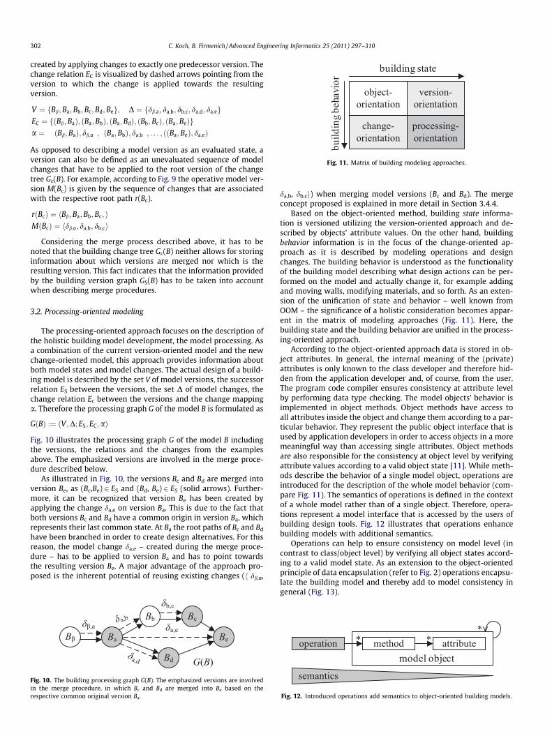
Fig. 11. Matrix of building modeling approaches.
302 C. Koch, B. Firmenich / Advanced Engineering Informatics 25 (2011) 297–310
created by applying changes to exactly one predecessor version. Thechange relation EC is visualized by dashed arrows pointing from theversion to which the change is applied towards the resultingversion.
V ¼ fBb; Ba;Bb;Bc;Bd;Beg; D ¼ fdb;a; da;b; db;c; da;d; da;egEC ¼ fðBb;BaÞ; ðBa;BbÞ; ðBa; BdÞ; ðBb;BcÞ; ðBa;BeÞga ¼ ðBb;BaÞ; db;a
� �; ðBa;BbÞ; da;b� �
; . . . ; ðBa; BeÞ; da;eð Þ� �
As opposed to describing a model version as an evaluated state, aversion can also be defined as an unevaluated sequence of modelchanges that have to be applied to the root version of the changetree Gc(B). For example, according to Fig. 9 the operative model ver-sion M(Bc) is given by the sequence of changes that are associatedwith the respective root path r(Bc).
rðBcÞ ¼ hBb;Ba;Bb;Bc; iMðBcÞ ¼ hdb;a; da;b; db;ci
Considering the merge process described above, it has to benoted that the building change tree Gc(B) neither allows for storinginformation about which versions are merged nor which is theresulting version. This fact indicates that the information providedby the building version graph GS(B) has to be taken into accountwhen describing merge procedures.
3.2. Processing-oriented modeling
The processing-oriented approach focuses on the description ofthe holistic building model development, the model processing. Asa combination of the current version-oriented model and the newchange-oriented model, this approach provides information aboutboth model states and model changes. The actual design of a build-ing model is described by the set V of model versions, the successorrelation ES between the versions, the set D of model changes, thechange relation Ec between the versions and the change mappinga. Therefore the processing graph G of the model B is formulated as
GðBÞ :¼ ðV ;D; ES; EC;aÞ
Fig. 10 illustrates the processing graph G of the model B includingthe versions, the relations and the changes from the examplesabove. The emphasized versions are involved in the merge proce-dure described below.
As illustrated in Fig. 10, the versions Bc and Bd are merged intoversion Be, as (Bc,Be) 2 ES and (Bd, Be) 2 ES (solid arrows). Further-more, it can be recognized that version Be has been created byapplying the change da,e on version Ba. This is due to the fact thatboth versions Bc and Bd have a common origin in version Ba, whichrepresents their last common state. At Ba the root paths of Bc and Bd
have been branched in order to create design alternatives. For thisreason, the model change da,e – created during the merge proce-dure – has to be applied to version Ba and has to point towardsthe resulting version Be. A major advantage of the approach pro-posed is the inherent potential of reusing existing changes (h db,a,
Fig. 10. The building processing graph G(B). The emphasized versions are involvedin the merge procedure, in which Bc and Bd are merged into Be based on therespective common original version Ba.
da,b, db,ci) when merging model versions (Bc and Bd). The mergeconcept proposed is explained in more detail in Section 3.4.4.
Based on the object-oriented method, building state informa-tion is versioned utilizing the version-oriented approach and de-scribed by objects’ attribute values. On the other hand, buildingbehavior information is in the focus of the change-oriented ap-proach as it is described by modeling operations and designchanges. The building behavior is understood as the functionalityof the building model describing what design actions can be per-formed on the model and actually change it, for example addingand moving walls, modifying materials, and so forth. As an exten-sion of the unification of state and behavior – well known fromOOM – the significance of a holistic consideration becomes appar-ent in the matrix of modeling approaches (Fig. 11). Here, thebuilding state and the building behavior are unified in the process-ing-oriented approach.
According to the object-oriented approach data is stored in ob-ject attributes. In general, the internal meaning of the (private)attributes is only known to the class developer and therefore hid-den from the application developer and, of course, from the user.The program code compiler ensures consistency at attribute levelby performing data type checking. The model objects’ behavior isimplemented in object methods. Object methods have access toall attributes inside the object and change them according to a par-ticular behavior. They represent the public object interface that isused by application developers in order to access objects in a moremeaningful way than accessing single attributes. Object methodsare also responsible for the consistency at object level by verifyingattribute values according to a valid object state [11]. While meth-ods describe the behavior of a single model object, operations areintroduced for the description of the whole model behavior (com-pare Fig. 11). The semantics of operations is defined in the contextof a whole model rather than of a single object. Therefore, opera-tions represent a model interface that is accessed by the users ofbuilding design tools. Fig. 12 illustrates that operations enhancebuilding models with additional semantics.
Operations can help to ensure consistency on model level (incontrast to class/object level) by verifying all object states accord-ing to a valid model state. As an extension to the object-orientedprinciple of data encapsulation (refer to Fig. 2) operations encapsu-late the building model and thereby add to model consistency ingeneral (Fig. 13).
Fig. 12. Introduced operations add semantics to object-oriented building models.
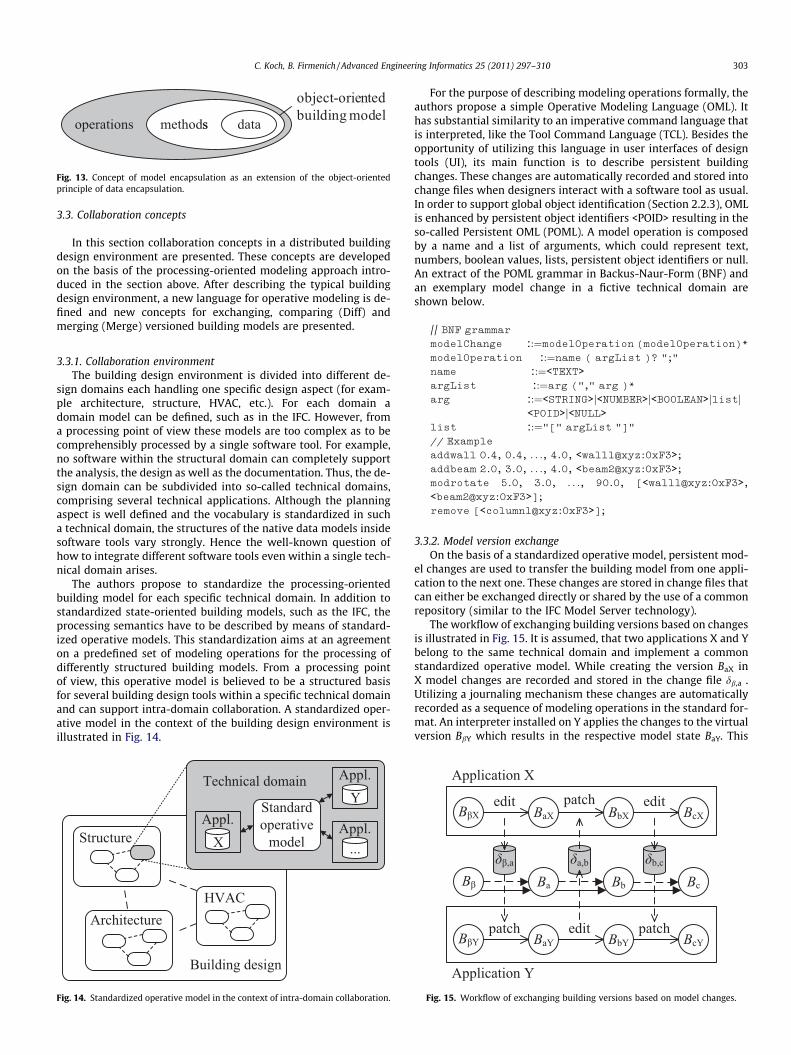
Fig. 13. Concept of model encapsulation as an extension of the object-orientedprinciple of data encapsulation.
C. Koch, B. Firmenich / Advanced Engineering Informatics 25 (2011) 297–310 303
3.3. Collaboration concepts
In this section collaboration concepts in a distributed buildingdesign environment are presented. These concepts are developedon the basis of the processing-oriented modeling approach intro-duced in the section above. After describing the typical buildingdesign environment, a new language for operative modeling is de-fined and new concepts for exchanging, comparing (Diff) andmerging (Merge) versioned building models are presented.
3.3.1. Collaboration environmentThe building design environment is divided into different de-
sign domains each handling one specific design aspect (for exam-ple architecture, structure, HVAC, etc.). For each domain adomain model can be defined, such as in the IFC. However, froma processing point of view these models are too complex as to becomprehensibly processed by a single software tool. For example,no software within the structural domain can completely supportthe analysis, the design as well as the documentation. Thus, the de-sign domain can be subdivided into so-called technical domains,comprising several technical applications. Although the planningaspect is well defined and the vocabulary is standardized in sucha technical domain, the structures of the native data models insidesoftware tools vary strongly. Hence the well-known question ofhow to integrate different software tools even within a single tech-nical domain arises.
The authors propose to standardize the processing-orientedbuilding model for each specific technical domain. In addition tostandardized state-oriented building models, such as the IFC, theprocessing semantics have to be described by means of standard-ized operative models. This standardization aims at an agreementon a predefined set of modeling operations for the processing ofdifferently structured building models. From a processing pointof view, this operative model is believed to be a structured basisfor several building design tools within a specific technical domainand can support intra-domain collaboration. A standardized oper-ative model in the context of the building design environment isillustrated in Fig. 14.
Fig. 14. Standardized operative model in the context of intra-domain collaboration.
For the purpose of describing modeling operations formally, theauthors propose a simple Operative Modeling Language (OML). Ithas substantial similarity to an imperative command language thatis interpreted, like the Tool Command Language (TCL). Besides theopportunity of utilizing this language in user interfaces of designtools (UI), its main function is to describe persistent buildingchanges. These changes are automatically recorded and stored intochange files when designers interact with a software tool as usual.In order to support global object identification (Section 2.2.3), OMLis enhanced by persistent object identifiers <POID> resulting in theso-called Persistent OML (POML). A model operation is composedby a name and a list of arguments, which could represent text,numbers, boolean values, lists, persistent object identifiers or null.An extract of the POML grammar in Backus-Naur-Form (BNF) andan exemplary model change in a fictive technical domain areshown below.
// BNF grammar
modelChange ::¼modelOperation (modelOperation)*modelOperation ::¼name ( argList )? ";"
name ::¼<TEXT>argList ::¼arg ("," arg )*
arg ::¼<STRING>j<NUMBER>j<BOOLEAN>jlistj<POID>j<NULL>
list ::¼"[" argList "]"
// Example
addwall 0.4, 0.4, . . ., 4.0, <wall1@xyz:0xF3>;addbeam 2.0, 3.0, . . ., 4.0, <beam2@xyz:0xF3>;modrotate 5.0, 3.0, . . ., 90.0, [<wall1@xyz:0xF3>,<beam2@xyz:0xF3>];remove [<column1@xyz:0xF3>];
3.3.2. Model version exchangeOn the basis of a standardized operative model, persistent mod-
el changes are used to transfer the building model from one appli-cation to the next one. These changes are stored in change files thatcan either be exchanged directly or shared by the use of a commonrepository (similar to the IFC Model Server technology).
The workflow of exchanging building versions based on changesis illustrated in Fig. 15. It is assumed, that two applications X and Ybelong to the same technical domain and implement a commonstandardized operative model. While creating the version BaX inX model changes are recorded and stored in the change file db,a .Utilizing a journaling mechanism these changes are automaticallyrecorded as a sequence of modeling operations in the standard for-mat. An interpreter installed on Y applies the changes to the virtualversion BbY which results in the respective model state BaY. This
Fig. 15. Workflow of exchanging building versions based on model changes.
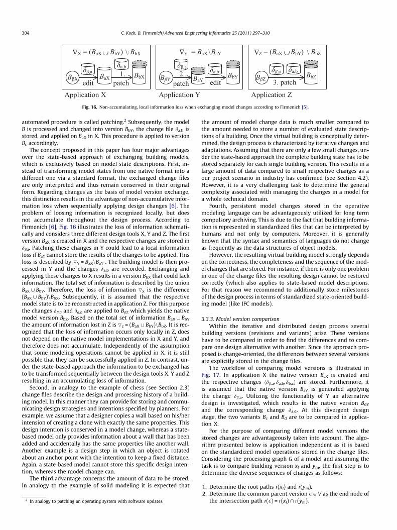
Fig. 16. Non-accumulating, local information loss when exchanging model changes according to Firmenich [5].
304 C. Koch, B. Firmenich / Advanced Engineering Informatics 25 (2011) 297–310
automated procedure is called patching.2 Subsequently, the modelB is processed and changed into version BbY, the change file da,b isstored, and applied on BaX in X. This procedure is applied to versionBc accordingly.
The concept proposed in this paper has four major advantagesover the state-based approach of exchanging building models,which is exclusively based on model state descriptions. First, in-stead of transforming model states from one native format into adifferent one via a standard format, the exchanged change filesare only interpreted and thus remain conserved in their originalform. Regarding changes as the basis of model version exchange,this distinction results in the advantage of non-accumulative infor-mation loss when sequentially applying design changes [6]. Theproblem of loosing information is recognized locally, but doesnot accumulate throughout the design process. According toFirmenich [6], Fig. 16 illustrates the loss of information schemati-cally and considers three different design tools X, Y and Z. The firstversion BaX is created in X and the respective changes are stored indba. Patching these changes in Y could lead to a local informationloss if BaY cannot store the results of the changes to be applied. Thisloss is described by OY = BaXnBaY . The building model is then pro-cessed in Y and the changes da,b are recorded. Exchanging andapplying these changes to X results in a version BbX that could lackinformation. The total set of information is described by the unionBaX [ BbY. Therefore, the loss of information Ox is the difference(BaX [ BbY)nBbX. Subsequently, it is assumed that the respectivemodel state is to be reconstructed in application Z. For this purposethe changes db,a and da,b are applied to BbZ which yields the nativemodel version BbZ. Based on the total set of information BaX [ BbY
the amount of information lost in Z is Oz = (BaX [ BbY)nBbZ. It is rec-ognized that the loss of information occurs only locally in Z, doesnot depend on the native model implementations in X and Y, andtherefore does not accumulate. Independently of the assumptionthat some modeling operations cannot be applied in X, it is stillpossible that they can be successfully applied in Z. In contrast, un-der the state-based approach the information to be exchanged hasto be transformed sequentially between the design tools X, Y and Zresulting in an accumulating loss of information.
Second, in analogy to the example of chess (see Section 2.3)change files describe the design and processing history of a build-ing model. In this manner they can provide for storing and commu-nicating design strategies and intentions specified by planners. Forexample, we assume that a designer copies a wall based on his/herintension of creating a clone with exactly the same properties. Thisdesign intention is conserved in a model change, whereas a state-based model only provides information about a wall that has beenadded and accidentally has the same properties like another wall.Another example is a design step in which an object is rotatedabout an anchor point with the intention to keep a fixed distance.Again, a state-based model cannot store this specific design inten-tion, whereas the model change can.
The third advantage concerns the amount of data to be stored.In analogy to the example of solid modeling it is expected that
2 In analogy to patching an operating system with software updates.
the amount of model change data is much smaller compared tothe amount needed to store a number of evaluated state descrip-tions of a building. Once the virtual building is conceptually deter-mined, the design process is characterized by iterative changes andadaptations. Assuming that there are only a few small changes, un-der the state-based approach the complete building state has to bestored separately for each single building version. This results in alarge amount of data compared to small respective changes as aour project scenario in industry has confirmed (see Section 4.2).However, it is a very challenging task to determine the generalcomplexity associated with managing the changes in a model fora whole technical domain.
Fourth, persistent model changes stored in the operativemodeling language can be advantageously utilized for long termcompulsory archiving. This is due to the fact that building informa-tion is represented in standardized files that can be interpreted byhumans and not only by computers. Moreover, it is generallyknown that the syntax and semantics of languages do not changeas frequently as the data structures of object models.
However, the resulting virtual building model strongly dependson the correctness, the completeness and the sequence of the mod-el changes that are stored. For instance, if there is only one problemin one of the change files the resulting design cannot be restoredcorrectly (which also applies to state-based model descriptions.For that reason we recommend to additionally store milestonesof the design process in terms of standardized state-oriented build-ing model (like IFC models).
3.3.3. Model version comparisonWithin the iterative and distributed design process several
building versions (revisions and variants) arise. These versionshave to be compared in order to find the differences and to com-pare one design alternative with another. Since the approach pro-posed is change-oriented, the differences between several versionsare explicitly stored in the change files.
The workflow of comparing model versions is illustrated inFig. 17. In application X the native version BcX is created andthe respective changes hdb,a,da,b,db,ci are stored. Furthermore, itis assumed that the native version BaY is generated applyingthe change db,a. Utilizing the functionality of Y an alternativedesign is investigated, which results in the native version BdY
and the corresponding change da,d. At this divergent designstage, the two variants Bc and Bd are to be compared in applica-tion X.
For the purpose of comparing different model versions thestored changes are advantageously taken into account. The algo-rithm presented below is application independent as it is basedon the standardized model operations stored in the change files.Considering the processing graph G of a model and assuming thetask is to compare building version xl and ym, the first step is todetermine the diverse sequences of changes as follows:
1. Determine the root paths r(xl) and r(ym).2. Determine the common parent version � 2 V as the end node of
the intersection path r(�) = r(xl) \ r(ym).
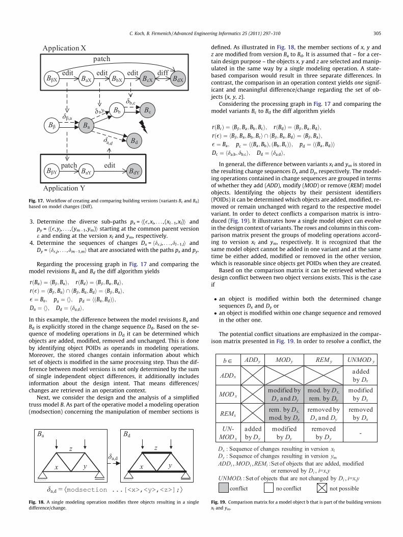
Fig. 17. Workflow of creating and comparing building versions (variants Bc and Bd)based on model changes (Diff).
C. Koch, B. Firmenich / Advanced Engineering Informatics 25 (2011) 297–310 305
3. Determine the diverse sub-paths px = h(�,xi, . . . , (xl�1,xl)i andpy = h(�,yj, . . . , (ym�1,ym)i starting at the common parent versione and ending at the version xl and ym, respectively.
4. Determine the sequences of changes Dx = hd�,i, . . . ,dl�1,li andDy = hd�,j, . . . ,dm�1,mi that are associated with the paths px and py.
Regarding the processing graph in Fig. 17 and comparing themodel revisions Ba and Bd the diff algorithm yields
rðBaÞ ¼ hBb;Bai; rðBdÞ ¼ hBb;Ba; Bdi;rð�Þ ¼ hBb;Bai \ hBb;Ba; Bdi ¼ hBb;Bai;� ¼ Ba; pa ¼ hi; pd ¼ hðBa;BdÞi;Da ¼ hi; Dd ¼ hda;di;
In this example, the difference between the model revisions Ba andBd is explicitly stored in the change sequence Dd. Based on the se-quence of modeling operations in Dd it can be determined whichobjects are added, modified, removed and unchanged. This is doneby identifying object POIDs as operands in modeling operations.Moreover, the stored changes contain information about whichset of objects is modified in the same processing step. Thus the dif-ference between model versions is not only determined by the sumof single independent object differences, it additionally includesinformation about the design intent. That means differences/changes are retrieved in an operation context.
Next, we consider the design and the analysis of a simplifiedtruss model B. As part of the operative model a modeling operation(modsection) concerning the manipulation of member sections is
Fig. 18. A single modeling operation modifies three objects resulting in a singledifference/change.
defined. As illustrated in Fig. 18, the member sections of x, y andz are modified from version Ba to Bd. It is assumed that – for a cer-tain design purpose – the objects x, y and z are selected and manip-ulated in the same way by a single modeling operation. A state-based comparison would result in three separate differences. Incontrast, the comparison in an operation context yields one signif-icant and meaningful difference/change regarding the set of ob-jects {x, y, z}.
Considering the processing graph in Fig. 17 and comparing themodel variants Bc to Bd the diff algorithm yields
rðBcÞ ¼ hBb;Ba;Bb;Bci; rðBdÞ ¼ hBb;Ba;Bdi;rð�Þ ¼ hBb;Ba;Bb;Bci \ hBb;Ba;Bdi ¼ hBb;Bai;� ¼ Ba; pc ¼ hðBa;BbÞ; ðBb;BcÞi; pd ¼ hðBa;BdÞiDc ¼ hda;b; db;ci; Dd ¼ hda;di;
In general, the difference between variants xl and ym is stored inthe resulting change sequences Dx and Dy, respectively. The model-ing operations contained in change sequences are grouped in termsof whether they add (ADD), modify (MOD) or remove (REM) modelobjects. Identifying the objects by their persistent identifiers(POIDs) it can be determined which objects are added, modified, re-moved or remain unchanged with regard to the respective modelvariant. In order to detect conflicts a comparison matrix is intro-duced (Fig. 19). It illustrates how a single model object can evolvein the design context of variants. The rows and columns in this com-parison matrix present the groups of modeling operations accord-ing to version xl and ym, respectively. It is recognized that thesame model object cannot be added in one variant and at the sametime be either added, modified or removed in the other version,which is reasonable since objects get POIDs when they are created.
Based on the comparison matrix it can be retrieved whether adesign conflict between two object versions exists. This is the caseif
� an object is modified within both the determined changesequences Dx and Dy or� an object is modified within one change sequence and removed
in the other one.
The potential conflict situations are emphasized in the compar-ison matrix presented in Fig. 19. In order to resolve a conflict, the
Fig. 19. Comparison matrix for a model object b that is part of the building versionsxl and ym.
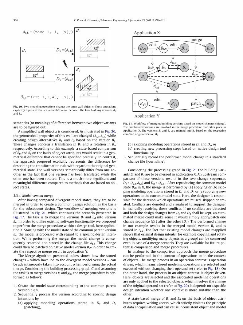
Fig. 20. Two modeling operations change the same wall object x. These operationsexplicitly represent the semantic difference between the two building versions Bb
and Bc.
Fig. 21. Workflow of merging building versions based on model changes (Merge).The emphasized versions are involved in the merge procedure that takes place inApplication X. The versions Bc and Bd are merged into Be based on the respectivecommon original version Ba.
306 C. Koch, B. Firmenich / Advanced Engineering Informatics 25 (2011) 297–310
semantics (or meaning) of differences between two object variantsare to be figured out.
A simplified wall object x is considered. As illustrated in Fig. 20,the geometrical properties of this wall are changed (da,b,da,c) whilecreating design alternatives Bb and Bc based on the version Ba.These changes concern a translation in Bb and a rotation in Bc,respectively. According to this example, a state-based comparisonof Bb and Bc on the basis of object attributes would result in a geo-metrical difference that cannot be specified precisely. In contrast,the approach proposed explicitly represents the difference bydescribing the transformation rule with regard to the original geo-metrical state. The wall versions semantically differ from one an-other in the fact that one version has been translated while theother one has been rotated. This is a much more significant andmeaningful difference compared to methods that are based on ob-ject states.
3.3.4. Model version mergeAfter having compared divergent model states, they are to be
merged in order to create a common design solution as the basisfor the subsequent design. The workflow of merging versions isillustrated in Fig. 21, which continues the scenario presented inFig. 17. The task is to merge the versions Bc and Bd into versionBe. In order to utilize existing software functionality we proposedto perform the merge procedure within a design tool, here applica-tion X. Starting with the model state of the common parent versionBa, the model is processed with regard to a specific design inten-tion. While performing the merge, the model change is conse-quently recorded and stored in the change file da,e. This changecould then be patched on native model version BaY in order to cre-ate the respective merge result in application Y.
The Merge algorithm presented below shows how the storedchanges – which have led to the divergent model versions – canbe advantageously taken into account when performing the actualmerge. Considering the building processing graph G and assumingthe task is to merge versions xl and ym, the merge procedure is per-formed as follows:
1. Create the model state corresponding to the common parentversion � 2 V.
2. Sequentially process the version according to specific designintentions by(a) applying modeling operations stored in Dx and Dy
(patching),
(b) skipping modeling operations stored in Dx and Dy, or(c) creating new processing steps based on native design tool
functionality.3. Sequentially record the performed model change in a standard
change file (journaling).
Considering the processing graph in Fig. 21 the building vari-ants Bc and Bd are to be merged in application X. An upstream com-parison of these versions results in the two change sequencesDc = hda,b,db,ci and Dd = hda,di. After reproducing the common modelstate BaX in X, the merge is performed by (a) applying or (b) skip-ping modeling operations stored in Dc and Dd or (c) applying newoperations to the current model state. Here, the designer is respon-sible for the decision which operations are reused, skipped or cre-ated. Conflicts are denoted and visualized to support the designerin manually resolving these conflicts. If no conflicts are detectedand both the design changes from Dc and Dd shall be kept, an auto-mated merge could make sense it would simply apply/patch onechange sequence (Dc) after the other (Dd). The performed changein our example results in the merged model version Be and isstored in da,e. The fact that existing model changes are reappliedshows that original design intents (for example copying and rotat-ing objects, modifying many objects as a group) can be conservedeven in case of a merge scenario. They are available for future po-tential comparison and merge procedures.
In analogy to the comparison approach the merge procedurecan be performed in the context of operations or in the contextof objects. The merge process in an operation context is operationdriven, which means, stored modeling operations are selected andexecuted without changing their operand set (refer to Fig. 18). Onthe other hand, the process in an object context is object driven.Here, objects are selected and the associated modeling operationsare only applied to the selected objects, which involves the changeof the original operand set (refer to Fig. 20). It depends on a specificdesign intention whether one context is more suitable than theother.
A state-based merge of Bc and Bd on the basis of object attri-butes requires writing access, which strictly violates the principleof data encapsulation and can cause inconsistent object and model
C. Koch, B. Firmenich / Advanced Engineering Informatics 25 (2011) 297–310 307
states. In contrast, the approach proposed is based on applyingmodeling operations. Since operations add to the consistency ofbuilding models in general, as explained in Section 2.3, this consis-tency is not endangered even in case of merging model versions.This is a significant advantage compared to methods that are basedon state-oriented model information only.
4. Implementation and design scenarios
4.1. Implementation
In order to verify the presented approach in principle, a stan-dardized operative model has been defined for the 2D reinforce-ment design domain. This model contains operations for adding,modifying and removing reinforcement objects (bar, stirrup, plac-ing range, etc.) and standard CAD objects (line, text, dimensioning).The Open Source engineering platform CADEMIA [36] was used asthe basis for our pilot implementation. Since CADEMIA is a modernobject-oriented design tool that implements parametric design ob-jects, it is well suited to verify our approach, which is applicable toobject-oriented design tools in general. Moreover, CADEMIA wasalso considered to be appropriate to implement project require-ments of our industry partner, who, to a large extent, deals with2D formwork and reinforcement design (see next section).
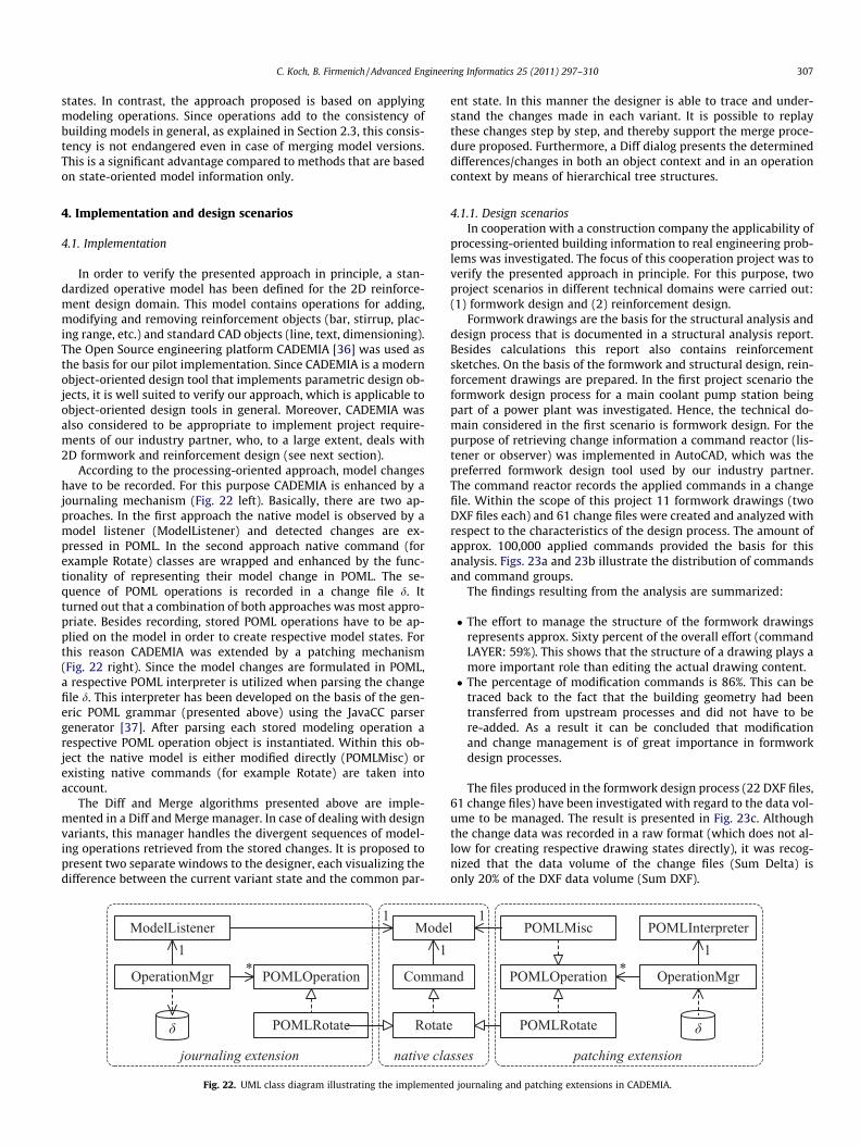
According to the processing-oriented approach, model changeshave to be recorded. For this purpose CADEMIA is enhanced by ajournaling mechanism (Fig. 22 left). Basically, there are two ap-proaches. In the first approach the native model is observed by amodel listener (ModelListener) and detected changes are ex-pressed in POML. In the second approach native command (forexample Rotate) classes are wrapped and enhanced by the func-tionality of representing their model change in POML. The se-quence of POML operations is recorded in a change file d. Itturned out that a combination of both approaches was most appro-priate. Besides recording, stored POML operations have to be ap-plied on the model in order to create respective model states. Forthis reason CADEMIA was extended by a patching mechanism(Fig. 22 right). Since the model changes are formulated in POML,a respective POML interpreter is utilized when parsing the changefile d. This interpreter has been developed on the basis of the gen-eric POML grammar (presented above) using the JavaCC parsergenerator [37]. After parsing each stored modeling operation arespective POML operation object is instantiated. Within this ob-ject the native model is either modified directly (POMLMisc) orexisting native commands (for example Rotate) are taken intoaccount.
The Diff and Merge algorithms presented above are imple-mented in a Diff and Merge manager. In case of dealing with designvariants, this manager handles the divergent sequences of model-ing operations retrieved from the stored changes. It is proposed topresent two separate windows to the designer, each visualizing thedifference between the current variant state and the common par-
Fig. 22. UML class diagram illustrating the implemente
ent state. In this manner the designer is able to trace and under-stand the changes made in each variant. It is possible to replaythese changes step by step, and thereby support the merge proce-dure proposed. Furthermore, a Diff dialog presents the determineddifferences/changes in both an object context and in an operationcontext by means of hierarchical tree structures.
4.1.1. Design scenariosIn cooperation with a construction company the applicability of
processing-oriented building information to real engineering prob-lems was investigated. The focus of this cooperation project was toverify the presented approach in principle. For this purpose, twoproject scenarios in different technical domains were carried out:(1) formwork design and (2) reinforcement design.
Formwork drawings are the basis for the structural analysis anddesign process that is documented in a structural analysis report.Besides calculations this report also contains reinforcementsketches. On the basis of the formwork and structural design, rein-forcement drawings are prepared. In the first project scenario theformwork design process for a main coolant pump station beingpart of a power plant was investigated. Hence, the technical do-main considered in the first scenario is formwork design. For thepurpose of retrieving change information a command reactor (lis-tener or observer) was implemented in AutoCAD, which was thepreferred formwork design tool used by our industry partner.The command reactor records the applied commands in a changefile. Within the scope of this project 11 formwork drawings (twoDXF files each) and 61 change files were created and analyzed withrespect to the characteristics of the design process. The amount ofapprox. 100,000 applied commands provided the basis for thisanalysis. Figs. 23a and 23b illustrate the distribution of commandsand command groups.
The findings resulting from the analysis are summarized:
� The effort to manage the structure of the formwork drawingsrepresents approx. Sixty percent of the overall effort (commandLAYER: 59%). This shows that the structure of a drawing plays amore important role than editing the actual drawing content.� The percentage of modification commands is 86%. This can be
traced back to the fact that the building geometry had beentransferred from upstream processes and did not have to bere-added. As a result it can be concluded that modificationand change management is of great importance in formworkdesign processes.
The files produced in the formwork design process (22 DXF files,61 change files) have been investigated with regard to the data vol-ume to be managed. The result is presented in Fig. 23c. Althoughthe change data was recorded in a raw format (which does not al-low for creating respective drawing states directly), it was recog-nized that the data volume of the change files (Sum Delta) isonly 20% of the DXF data volume (Sum DXF).
d journaling and patching extensions in CADEMIA.
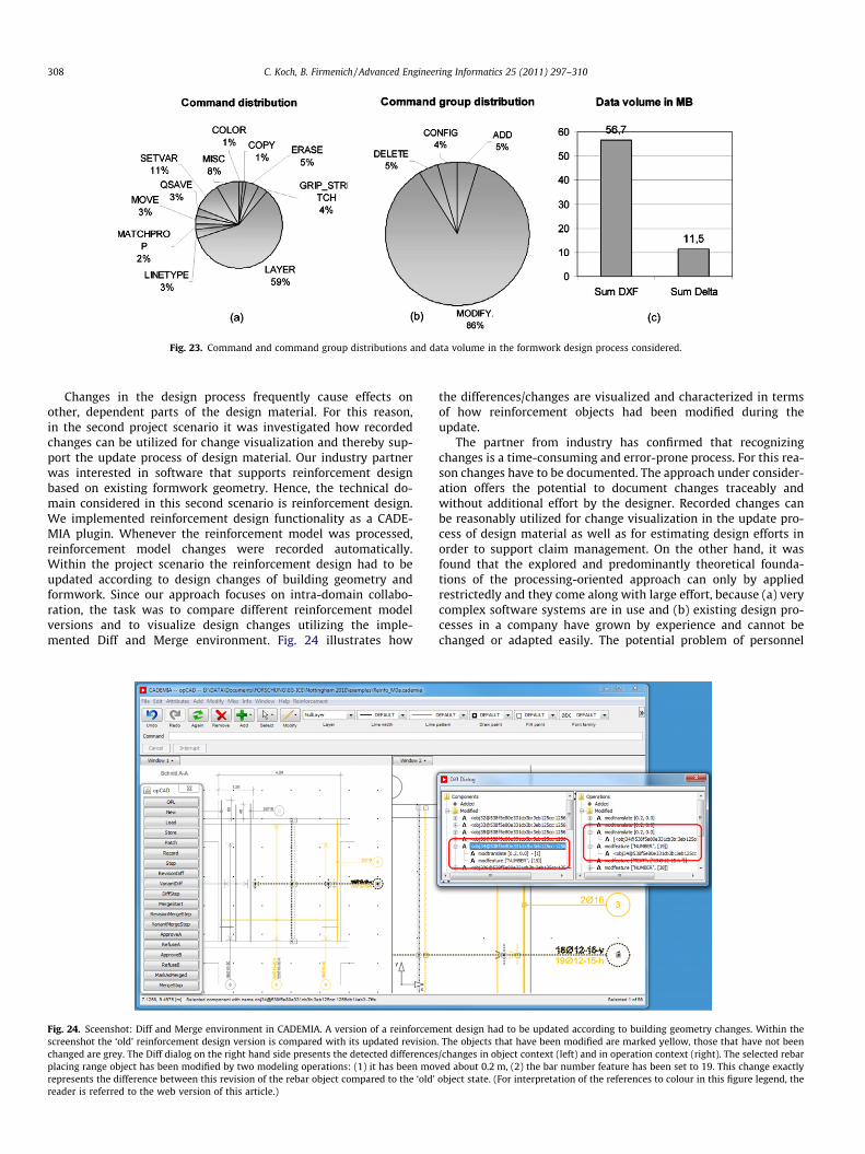
Fig. 23. Command and command group distributions and data volume in the formwork design process considered.
308 C. Koch, B. Firmenich / Advanced Engineering Informatics 25 (2011) 297–310
Changes in the design process frequently cause effects onother, dependent parts of the design material. For this reason,in the second project scenario it was investigated how recordedchanges can be utilized for change visualization and thereby sup-port the update process of design material. Our industry partnerwas interested in software that supports reinforcement designbased on existing formwork geometry. Hence, the technical do-main considered in this second scenario is reinforcement design.We implemented reinforcement design functionality as a CADE-MIA plugin. Whenever the reinforcement model was processed,reinforcement model changes were recorded automatically.Within the project scenario the reinforcement design had to beupdated according to design changes of building geometry andformwork. Since our approach focuses on intra-domain collabo-ration, the task was to compare different reinforcement modelversions and to visualize design changes utilizing the imple-mented Diff and Merge environment. Fig. 24 illustrates how
Fig. 24. Sceenshot: Diff and Merge environment in CADEMIA. A version of a reinforcemscreenshot the ‘old’ reinforcement design version is compared with its updated revisionchanged are grey. The Diff dialog on the right hand side presents the detected differencesplacing range object has been modified by two modeling operations: (1) it has been movrepresents the difference between this revision of the rebar object compared to the ‘old’reader is referred to the web version of this article.)
the differences/changes are visualized and characterized in termsof how reinforcement objects had been modified during theupdate.
The partner from industry has confirmed that recognizingchanges is a time-consuming and error-prone process. For this rea-son changes have to be documented. The approach under consider-ation offers the potential to document changes traceably andwithout additional effort by the designer. Recorded changes canbe reasonably utilized for change visualization in the update pro-cess of design material as well as for estimating design efforts inorder to support claim management. On the other hand, it wasfound that the explored and predominantly theoretical founda-tions of the processing-oriented approach can only by appliedrestrictedly and they come along with large effort, because (a) verycomplex software systems are in use and (b) existing design pro-cesses in a company have grown by experience and cannot bechanged or adapted easily. The potential problem of personnel
ent design had to be updated according to building geometry changes. Within the. The objects that have been modified are marked yellow, those that have not been/changes in object context (left) and in operation context (right). The selected rebared about 0.2 m, (2) the bar number feature has been set to 19. This change exactlyobject state. (For interpretation of the references to colour in this figure legend, the
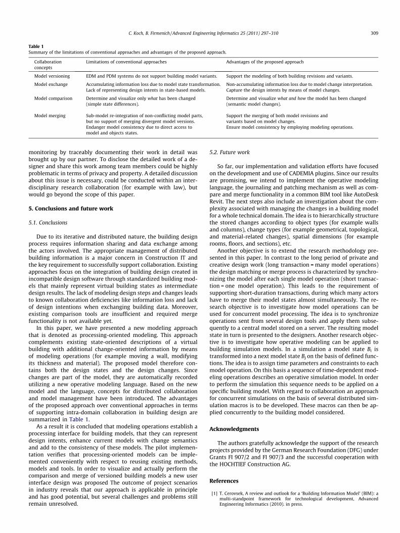
Table 1Summary of the limitations of conventional approaches and advantages of the proposed approach.
Collaborationconcepts
Limitations of conventional approaches Advantages of the proposed approach
Model versioning EDM and PDM systems do not support building model variants. Support the modeling of both building revisions and variants.
Model exchange Accumulating information loss due to model state transformation. Non-accumulating information loss due to model change interpretation.Lack of representing design intents in state-based models. Capture the design intents by means of model changes.
Model comparison Determine and visualize only what has been changed(simple state differences).
Determine and visualize what and how the model has been changed(semantic model changes).
Model merging Sub-model re-integration of non-conflicting model parts,but no support of merging divergent model versions.
Support the merging of both model revisions andvariants based on model changes.
Endanger model consistency due to direct access tomodel and objects states.
Ensure model consistency by employing modeling operations.
C. Koch, B. Firmenich / Advanced Engineering Informatics 25 (2011) 297–310 309
monitoring by traceably documenting their work in detail wasbrought up by our partner. To disclose the detailed work of a de-signer and share this work among team members could be highlyproblematic in terms of privacy and property. A detailed discussionabout this issue is necessary, could be conducted within an inter-disciplinary research collaboration (for example with law), butwould go beyond the scope of this paper.
5. Conclusions and future work
5.1. Conclusions
Due to its iterative and distributed nature, the building designprocess requires information sharing and data exchange amongthe actors involved. The appropriate management of distributedbuilding information is a major concern in Construction IT andthe key requirement to successfully support collaboration. Existingapproaches focus on the integration of building design created inincompatible design software through standardized building mod-els that mainly represent virtual building states as intermediatedesign results. The lack of modeling design steps and changes leadsto known collaboration deficiencies like information loss and lackof design intentions when exchanging building data. Moreover,existing comparison tools are insufficient and required mergefunctionality is not available yet.
In this paper, we have presented a new modeling approachthat is denoted as processing-oriented modeling. This approachcomplements existing state-oriented descriptions of a virtualbuilding with additional change-oriented information by meansof modeling operations (for example moving a wall, modifyingits thickness and material). The proposed model therefore con-tains both the design states and the design changes. Sincechanges are part of the model, they are automatically recordedutilizing a new operative modeling language. Based on the newmodel and the language, concepts for distributed collaborationand model management have been introduced. The advantagesof the proposed approach over conventional approaches in termsof supporting intra-domain collaboration in building design aresummarized in Table 1.
As a result it is concluded that modeling operations establish aprocessing interface for building models, that they can representdesign intents, enhance current models with change semanticsand add to the consistency of these models. The pilot implemen-tation verifies that processing-oriented models can be imple-mented conveniently with respect to reusing existing methods,models and tools. In order to visualize and actually perform thecomparison and merge of versioned building models a new userinterface design was proposed The outcome of project scenariosin industry reveals that our approach is applicable in principleand has good potential, but several challenges and problems stillremain unresolved.
5.2. Future work
So far, our implementation and validation efforts have focusedon the development and use of CADEMIA plugins. Since our resultsare promising, we intend to implement the operative modelinglanguage, the journaling and patching mechanism as well as com-pare and merge functionality in a common BIM tool like AutoDeskRevit. The next steps also include an investigation about the com-plexity associated with managing the changes in a building modelfor a whole technical domain. The idea is to hierarchically structurethe stored changes according to object types (for example wallsand columns), change types (for example geometrical, topological,and material-related changes), spatial dimensions (for examplerooms, floors, and sections), etc.
Another objective is to extend the research methodology pre-sented in this paper. In contrast to the long period of private andcreative design work (long transaction = many model operations)the design matching or merge process is characterized by synchro-nizing the model after each single model operation (short transac-tion = one model operation). This leads to the requirement ofsupporting short-duration transactions, during which many actorshave to merge their model states almost simultaneously. The re-search objective is to investigate how model operations can beused for concurrent model processing. The idea is to synchronizeoperations sent from several design tools and apply them subse-quently to a central model stored on a server. The resulting modelstate in turn is presented to the designers. Another research objec-tive is to investigate how operative modeling can be applied tobuilding simulation models. In a simulation a model state Bi istransformed into a next model state Bj on the basis of defined func-tions. The idea is to assign time parameters and constraints to eachmodel operation. On this basis a sequence of time-dependent mod-eling operations describes an operative simulation model. In orderto perform the simulation this sequence needs to be applied on aspecific building model. With regard to collaboration an approachfor concurrent simulations on the basis of several distributed sim-ulation macros is to be developed. These macros can then be ap-plied concurrently to the building model considered.
Acknowledgments
The authors gratefully acknowledge the support of the researchprojects provided by the German Research Foundation (DFG) underGrants FI 907/2 and FI 907/3 and the successful cooperation withthe HOCHTIEF Construction AG.
References
[1] T. Cerovsek, A review and outlook for a ‘Building Information Model’ (BIM): amulti-standpoint framework for technological development, AdvancedEngineering Informatics (2010). in press.
310 C. Koch, B. Firmenich / Advanced Engineering Informatics 25 (2011) 297–310
[2] H. Wang, B. Akinci, J.H. Garrett Jr., E. Nyberg, K.A. Reed, Semi-automated modelmatching using version difference, Advanced Engineering Informatics 23(2009) 1–11.
[3] W. Shen, Q. Hao, H. Mak, J. Neelamkavil, H. Xie, J. Dickinson, R. Thomas, A.Pardasani, H. Xue, Systems integration and collaboration in architecture,engineering, construction, and facilities management: a review, AdvancedEngineering Informatics 24 (2) (2010) 196–207.
[4] C. Eastman, P. Teicholz, R. Sacks, K. Liston, BIM Handbook: A Guide to BuildingInformation Modeling for Owners, Managers, Designers, Engineers, andContractors, John Wiley and Sons, 2008.
[5] R. Howard, B.-C. Björk, Building information modelling – experts’ views onstandardisation and industry deployment, Advanced Engineering Informatics22 (2) (2008) 271–280.
[6] B. Firmenich, A novel modelling approach for the exchange of CAD informationin civil engineering, in: A. Dikbas, R. Scherer (Eds.), Proceedings of the FifthEuropean Conference on Product and Process Modelling in the Building andrelated Industries: eWork and eBusiness in Architecture, Engineering andConstruction (ECPPM), A.A. Balkema Publishers, Leiden/ London/ New York,2004.
[7] W. Gielingh, An assessment of the current state of product data technologies,Computer Aided Design 40 (7) (2008) 750–759.
[8] J. Kim, M.J. Pratt, R.G. Iyer, R.D. Sriram, Standardized data exchange of CADmodels with design intent, Computer-Aided Design 40 (7) (2008) 760–777.
[9] C. Koch, Bauwerksmodellierung im kooperativen Planungsprozess: Mit derObjektorientierung zur Verarbeitungsorientierung, Ph.D. Thesis, Bauhaus-Universität Weimar, 2008 (in German).
[10] T. Richter, K. Beucke, Diff and merge for net-distributed applications in civilengineering, in: Proceedings of the 11th International Conference onComputing in Civil and Building Engineering (ICCCBE-XI), Université duQuébec, Montreal, Canada, 2006, pp. 3716–3725.
[11] G. Booch, R.A. Maksimchuk, M.W. Engel, B.J. Young, J. Conallen, K.A. Houston,Object-oriented Analysis and Design with Applications, 3rd ed., Addison-Wesley, 2007.
[12] C. Koch, B. Firmenich, Building information processing in the context ofcooperative design, in: W. Huhnt (Ed.), Computing in Engineering – EG-ICEConference 2009, Shaker Verlag, 2009, pp. 169–176.
[13] J. Corney, T. Lim, 3D modeling with ACIS, Stirling, Saxe-Coburg, 2001.[14] R.H. Katz, Toward a unified framework for version modeling in engineering
databases, ACM Computing Surveys 22 (4) (1990) 375–409.[15] B. Firmenich, Consistency of a shared versioned model for distributed
cooperation, Computer-Aided Civil and Infrastructure Engineering 20 (6)(2005) 424–430.
[16] R. Conradi, B. Westfechtel, Version models for software configurationmanagement, ACM Computer Survey 30 (2) (1998) 232–282.
[17] J. A Abdalla, T. M Eltayeb, Version and configuration model for structuraldesign objects: design and implementation, Journal of Computing in CivilEngineering 22 (3) (2008) 147–158.
[18] J.C. Miles, W.A. Gray, T.W. Carnduff, I. Santoyridis, A. Faulconbridge, Versioningand configuration management in design using CAD and complex wrappedobjects, Artificial Intelligence in Engineering 14 (2000) 249–260.
[19] P. Pahl, R. Damrath, Mathematical Foundations of Computational Engineering– A Handbook, Springer, Berlin, 2001.
[20] D. Hajjar, S.M. AbouRizk, Integrating document management with project andcompany data, Journal of Computing in Civil Engineering 14 (1) (2000)70–77.
[21] A. Borrmann, M. Schorr, M. Obergriesser, Y. Ji, I.-C. Wu, W. Guenthner, T.Euringer, E. Rank, Using product data management systems for civilengineering projects – potentials and obstacles, in: Proceedings of the 2009ASCE International Workshop on Computing in Civil Engineering, 2009.
[22] B.-C. Björk, Electronic document management in construction – researchissues and results, Journal of Information Technology in Construction (8)(2003) 105–117.
[23] B. Firmenich, C. Koch, T. Richter, D.G. Beer, Versioning structured object setsusing text based version control systems, in: R.J. Scherer, P. Katranuschkov, S.-E. Schapke (Eds.), Proceedings of the 22nd CIB-W78 Conference on InformationTechnology in Construction, Institute of Construction Informatics, Dresden,2005, pp. 105–112.
[24] M. Weise, Ein Ansatz zur Abbildung von Änderungen in der modell-basiertenObjektplanung, Ph.D. Thesis, Technische Universität Dresden, 2006 (inGerman).
[25] T. Liebich, Y. Adachi, J. Forester, J. Hyvarinen, K. Karstila, K. Reed, S. Richter, J.Wix, Industry foundation classes IFC 2x edition 3 technical corrigendum 1,buildingSMART International Alliance for Interoperability (IAI), 2007.
[26] A. Kiviniemi, M. Fischer, V. Bazjanac, Integration of multiple product models:IFC model servers as a potential solution, in: Proceedings of the 22nd CIB-W78Conference on Information Technology in Construction, Dresden, Germany,2005, pp. 37–40.
[27] G.-H. Choi, D. Mun, S. Han, Exchange of cad part models based on the macro-parametric approach, International Journal of CAD/CAM 2 (1) (2002)13–21.
[28] D. Mun, S. Han, J. Kim, Y. Oh, A set of standard modeling commands for thehistory-based parametric approach, Computer-Aided Design 35 (13) (2003)1171–1179.
[29] M.J. Pratt, B.D. Anderson, T. Ranger, Towards the standardized exchange ofparameterized feature-based cad models, Computer-Aided Design 37 (12)(2005) 1251–1265.
[30] M. Pratt, J. Kim, Experience in the exchange of procedural shape models usingISO 10303 (STEP), in: Proceedings of the 2006 ACM Symposium on Solid andPhysical Modeling (SPM), New York, USA, 2006, pp. 229–238.
[31] Product Data Representation and Exchange: Integrated Generic Resource:Procedural and Hybrid Representation, International Organization forStandardization (ISO), 2002.
[32] Product Data Representation and Exchange: Integrated Application Resource:Construction History Features, International Organization for Standardization(ISO), 2003.
[33] Product Data Representation and Exchange: Integrated Application Resource:Standard Modelling Commands for the Procedural Exchange of 2D CADModels, International Organization for Standardization (ISO), 2004.
[34] C.A. Ellis, S.J. Gibbs, G. Rein, Groupware : some issues and experiences,Communications of the ACM 34 (1) (1991) 39–58.
[35] E. Gamma, R. Helm, R. Johnson, J. Vlissides, Design Patterns: Elements ofReusable Object-Oriented Software, 24. Printing, Addison-Wesley, Boston,2002.
[36] Firmenich, C. Koch, T. Richter, A.H. Olivier, D.G. Beer, CADEMIA: A platform forthe development of civil engineering applications, in: Proceedings of the 12thInternational Conference on Computing in Civil and Building Engineering(ICCCBE-XII), Tsinghua University, Beijing, 2008.
[37] T. Copeland, Parsers with JavaCC, Centennial Books, Alexandria, 2007.