
AN ANALYTICAL SOLUTION FOR CYLINDRICAL CONCRETE TANK …
22
International Journal of Advanced Structural Engineering, Vol. 2, No. 1, Pages 69-90, July 2010 © Islamic Azad University, South Tehran Branch Published online July 2010 at (http://journals.azad.ac.ir/IJASE) 69 AN ANALYTICAL SOLUTION FOR CYLINDRICAL CONCRETE TANK ON DEFORMABLE SOIL Shirish Vichare 1 and Mandar M. Inamdar 2 Department of Civil Engineering, Indian Institute of Technology Bombay, Mumbai, India Received 16 May 2010 Revised 23 July 2010 Accepted 29 July 2010 Cylindrical concrete tanks are commonly used in wastewater treatment plants. These are usually clarifier tanks. Design codes of practice provide methods to calculate design forces in the wall and raft of such tanks. These methods neglect self-weight of tank material and assume extreme, namely ‘fixed’ and ‘hinged’ conditions for the wall bottom. However, when founded on deformable soil, the actual condition at the wall bottom is neither fixed nor hinged. Further, the self-weight of the tank wall does affect the design forces. Thus, it is required to offer better insight of the combined effect of deformable soil and bottom raft stiffness on the design forces induced in such cylindrical concrete tanks. A systematic analytical method based on fundamental equations of shells is presented in this paper. Important observations on variation of design forces across the wall and the raft with different soil conditions are given. Set of commonly used tanks, are analysed using equations developed in the paper and are appended at the end. Keywords: clarifier, circular concrete tanks, elastic foundation, soil-structure interaction, structural design 1. Introduction Clarifier tank is one of the important components of wastewater treatment plant (Arceivala, 1998). Clarifier tank in most cases is a cylindrical concrete tank. Its function is to facilitate settlement of solids. The founding level of treatment units in the wastewater treatment plant is dictated by the overall hydraulics. The clarifiers are usually required to be founded near grade 1 Ph.D. Candidate 2 Assistant Professor Correspondence to: Dr. Mandar M. Inamdar, Department of Civil Engineering, Indian Institute of Technology Bombay, Powai, Mumbai 400 076, India, E-mail: [email protected]
Transcript of AN ANALYTICAL SOLUTION FOR CYLINDRICAL CONCRETE TANK …

International Journal of Advanced Structural Engineering, Vol. 2, No. 1, Pages 69-90, July 2010
© Islamic Azad University, South Tehran Branch
Published online July 2010 at (http://journals.azad.ac.ir/IJASE)
69
AN ANALYTICAL SOLUTION FOR CYLINDRICAL CONCRETE TANK ON DEFORMABLE SOIL
Shirish Vichare1 and Mandar M. Inamdar2 Department of Civil Engineering, Indian Institute of Technology Bombay, Mumbai, India
Received 16 May 2010 Revised 23 July 2010
Accepted 29 July 2010
Cylindrical concrete tanks are commonly used in wastewater treatment plants. These are usually clarifier tanks. Design codes of practice provide methods to calculate design forces in the wall and raft of such tanks. These methods neglect self-weight of tank material and assume extreme, namely ‘fixed’ and ‘hinged’ conditions for the wall bottom. However, when founded on deformable soil, the actual condition at the wall bottom is neither fixed nor hinged. Further, the self-weight of the tank wall does affect the design forces. Thus, it is required to offer better insight of the combined effect of deformable soil and bottom raft stiffness on the design forces induced in such cylindrical concrete tanks. A systematic analytical method based on fundamental equations of shells is presented in this paper. Important observations on variation of design forces across the wall and the raft with different soil conditions are given. Set of commonly used tanks, are analysed using equations developed in the paper and are appended at the end. Keywords: clarifier, circular concrete tanks, elastic foundation, soil-structure interaction, structural design
1. Introduction
Clarifier tank is one of the important components of wastewater treatment plant (Arceivala, 1998). Clarifier tank in most cases is a cylindrical concrete tank. Its function is to facilitate settlement of solids. The founding level of treatment units in the wastewater treatment plant is dictated by the overall hydraulics. The clarifiers are usually required to be founded near grade 1 Ph.D. Candidate 2 Assistant Professor Correspondence to: Dr. Mandar M. Inamdar, Department of Civil Engineering, Indian Institute of Technology Bombay, Powai, Mumbai 400 076, India, E-mail: [email protected]

S. Vichare et al.
/ IJASE: Vol. 2, No. 1, July 2010 70
level. At grade level, firm foundation may not be available, and thus in most cases the clarifier tank rests on deformable soils.
The design tables available in, say, the Portland Cement Association publication (PCA, 1993) or Indian Standard Publication (IS: 3370, part IV – 2004) are popular references for the design of cylindrical concrete tanks. In these tables, and in most other design handbooks, the analysis is simplified by taking ideal boundary conditions at the base of the wall. It is a common practice to analyze the tank wall assuming a fixed base and a hinged base for calculating vertical moment and hoop tension, respectively. The effects of the base raft and its interaction with the underlying soil, are usually neglected to limit complexity of the analysis. Further, self-weight of the tank is also neglected. Such approximations often lead the designers to be excessively conservative, and in some cases, may lead to inadequate designs.
Many standard books and researchers have worked on the issues related to circular water tanks and flexible nature of soil. Timoshenko and Krieger (1987) solved the problem of circular plate on elastic foundation, Kelkar and Sewell (1987) presented analytical solution for a circular tank in which flexibility of tank raft is considered. Melerski (1991) presented a computer program for elastic analysis of axisymmetric cylindrical storage tanks. Kukreti, et al. (1993) proposed analytical procedure by using energy methods to predict the behavior of liquid storage tank resting on elastic soil medium, which is modeled as elastic isotropic half space. Kukreti and Siddiqi (1997) presented analysis of fluid storage tanks including foundation-superstructure interaction using quadrature method. El Mezzaini (2006) presented effects of soil-structure interaction on the analysis of cylindrical tanks using computer software. The method given by him brought out the importance of sub grade interaction on design forces and settlement of such tanks. Effect of self-weight, which is usually neglected, was also considered in his method. Ziari and Kianoush (2008) investigated effect of direct tension on crack width in reinforced concrete members and pointed out that exceeding the direct tension beyond permissible limit can cause leakage.
This paper provides a systematic and simplified analytical treatment for analysis of cylindrical tanks, which rest on deformable soil. Here, we have combined results given by Timoshenko and Krieger (1987), which give complete solution for the circular plate on elastic foundation with results provided by Kelkar and Sewell (1987), which incorporates flexibility of raft into calculation of design forces for a circular water tank. The results obtained from analytical solution are compared with corresponding computer simulation using ABAQUS 6.8 for a typical tank resting on deformable soil. Further, design forces for large number of tanks, which form a set of clarifier tanks of commonly used dimensions, are presented in Appendix – I for ready reference. Based on the results, observations are presented, which are hoped to be useful for design engineers.

An Analytical Solution for Cylindrical Concrete Tank on Deformable Soil
IJASE: Vol. 2, No. 1, July 2010 / 71
2. Problem Definition and Modeling
In this Section, the systematic outline of the analysis is provided. 2.1. Modeling
Following Timoshenko and Krieger (1987), we model the soil as Winkler’s foundation with stiffness k. Since soil is a highly non-homogeneous and non-linear material, it is difficult to arrive at precise value of k for a given site. It is presumed that the acceptable value of k is available. The tank is modeled as an elastic cylindrical tank of radius a, height H and thickness t. The Young’s modulus, density and Poisson’s ratio of the tank material are E, γc, and ν, respectively. The density of liquid contained in the tank is γ. The problem is axi-symmetric and the scope is limited to tanks resting at grade level only. 2.2. Loads
As the tank is considered to be resting at grade level, there is no uplift force on bottom raft due to ground water. Walls are subjected to hydraulic load from inner side of the tank. The vertical load of the water body and self-weight of the base slab of the tank are balanced by the reaction from soil and thus do not create any moment, shear or tension force. Only the hydrostatic load and self-weight of the tank wall contribute to the design forces. 2.3. Analysis Methodology
For analysis purpose, the tank is disassembled as combination of the cylindrical part, and bottom raft resting on an elastic foundation as shown in Figure 1a. To find the interaction forces and moments between the cylinder and the raft portion we use a flexibility approach wherein the displacements and rotations are made compatible.
For finalizing the thickness and reinforcement of wall and raft, three design forces, namely i) moment along the wall, ii) hoop tension in the wall, and iii) moment across the raft are required. The design method suggested by various codes of practice assumes two extreme conditions, namely, ‘fixity’ and ‘hinged’ at wall bottom for calculating these design forces. The codes assume that the raft rests on firm foundation. In practice, however, as the tank rests on deformable soil, the bottom condition for the wall, is neither fixed nor hinged, due to flexibility of raft (Kelkar and Sewell, 1987) as well as elastic stiffness of soil. This paper provides a systematic and simplified analytical method to calculate bending moment and shear force at bottom edge of the circular wall incorporating both these effects. With knowledge of these values, bending moment and tension at any point in the wall and bending moment across the raft can easily be calculated.

S. Vichare et al.
/ IJASE: Vol. 2, No. 1, July 2010 72
The tension in the raft, corresponds to shear at the bottom of the wall. Moment in the raft is calculated from the edge moment induced at the bottom of the wall. The results obtained by analytical method are compared with the simulation results obtained by using ABAQUS 6.8. Interaction forces between of the wall and raft are shown in Figure 1a. The deflected shape of the wall is shown in Figure 1b.
(a) (b) Figure 1. a) Interaction forces between wall and raft; b) Deflected shape of tank
To satisfy the compatibility condition, horizontal displacement and rotation at the wall-raft joint induced must be equal to the horizontal displacement and rotation induced due to extension and bending of the raft. 3. Calculation of Design Forces
Initially, rotation δθ at wall-raft joint due to bending of raft, and horizontal displacement δ due to radial extension of raft are calculated. Next, horizontal displacement and rotation at the bottom edge of circular wall due to hydraulic load and self-weight of wall are calculated. Then, applying compatibility condition at the wall-raft joint, shear force F and moment M at the joint are calculated. Finally, hoop tension and wall moment as well as base raft moment are calculated.
3.1. Calculation for Rotation δθ at Wall-Raft Joint due to Bending of Raft
For a circular plate on elastic foundation, the fundamental Equation for deflection w is (Timoshenko and Krieger, 1987):
( )Drq
drdw
rdrwd
drd
rdrd
=++ ⎟⎟⎠
⎞⎜⎜⎝
⎛⎟⎠⎞
⎜⎝⎛⎟⎠⎞
⎜⎝⎛
⎟⎟⎠
⎞⎜⎜⎝
⎛⎟⎠⎞
⎜⎝⎛⎟⎠⎞
⎜⎝⎛ 11
2
2
2
2
(1)
where, r is radial distance from centre of the raft, w is vertical deflection of the plate and q is intensity of continuously distributed load, k is stiffness of soil, and D is flexural rigidity as given
in Table 2. Introducing, ∆ = ⎟⎠⎞
⎜⎝⎛⎟⎠⎞
⎜⎝⎛+
drd
rdrd 1
2
2
and 4
1lD
k= , for kwq −= , Equation (1) becomes:
δθ
An Analytical Solution for Cylindrical Concrete Tank on Deformable Soil
IJASE: Vol. 2, No. 1, July 2010 / 73
0=+ΔΔ ww (2)
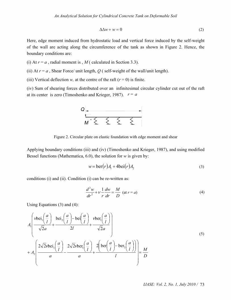
Here, edge moment induced from hydrostatic load and vertical force induced by the self-weight of the wall are acting along the circumference of the tank as shown in Figure 2. Hence, the boundary conditions are:
(i) At r = a , radial moment is , M ( calculated in Section 3.3).
(ii) At r = a , Shear Force/ unit length, Q ( self-weight of the wall/unit length).
(iii) Vertical deflection w, at the centre of the raft (r = 0) is finite.
(iv) Sum of shearing forces distributed over an infinitesimal circular cylinder cut out of the raft at its center is zero (Timoshenko and Krieger, 1987).
Figure 2. Circular plate on elastic foundation with edge moment and shear
Applying boundary conditions (iii) and (iv) (Timoshenko and Krieger, 1987), and using modified Bessel functions (Mathematica, 6.0), the solution for w is given by:
( ) ( ) 21 bei4ber ArArw += (3)
conditions (i) and (ii). Condition (i) can be re-written as:
DM
drdw
rdrwd
=+1
2
2
ν (at r = a) (4)
Using Equations (3) and (4):
DM
lla
la
ala
ala
A
ala
lla
la
ala
A
=
⎟⎟⎟⎟⎟
⎠
⎞
⎜⎜⎜⎜⎜
⎝
⎛⎟⎟⎠
⎞⎜⎜⎝
⎛⎟⎠⎞
⎜⎝⎛−⎟
⎠⎞
⎜⎝⎛
+⎟⎠⎞
⎜⎝⎛
−⎟⎠⎞
⎜⎝⎛
+
⎟⎟⎟⎟
⎠
⎞
⎜⎜⎜⎜
⎝
⎛⎟⎠⎞
⎜⎝⎛
+⎟⎠⎞
⎜⎝⎛−⎟
⎠⎞
⎜⎝⎛
+⎟⎠⎞
⎜⎝⎛
211
2
121
1
berber2ber22bei22
2
ber
2
beibei
2
bei
νν
νν
(5)
r = a

S. Vichare et al.
/ IJASE: Vol. 2, No. 1, July 2010 74
Condition (ii) can be re-written as:
⎜⎜⎝
⎛=⎟
⎠⎞+
DQ
drdw
rdrwd
drd 1
2
2
(at r = a) (6)
Using Equations (3) and (6):
DQ
lla
laA
lla
laA
=⎟⎠
⎞⎜⎝
⎛⎟⎠⎞
⎜⎝⎛+⎟
⎠⎞
⎜⎝⎛
+⎟⎠
⎞⎜⎝
⎛⎟⎠⎞
⎜⎝⎛−⎟
⎠⎞
⎜⎝⎛
2
112
2
111
2
beiber4
2
beiber
(7)
By solving Equations (5) and (7) simultaneously, values of A1 and A2 obtained are:
( ) ( )
( ) ⎟⎟
⎠
⎞
⎜⎜
⎝
⎛
⎟⎟
⎠
⎞
⎜⎜
⎝
⎛⎟⎠⎞
⎜⎝⎛+⎟
⎠⎞
⎜⎝⎛−−⎟
⎟⎠
⎞⎜⎜⎝
⎛⎟⎟⎠
⎞⎜⎜⎝
⎛⎟⎠⎞
⎜⎝⎛+⎟
⎠⎞
⎜⎝⎛
⎟⎠⎞
⎜⎝⎛+⎟⎟
⎠
⎞⎜⎜⎝
⎛⎟⎠⎞
⎜⎝⎛−⎟
⎠⎞
⎜⎝⎛
⎟⎠⎞
⎜⎝⎛
⎟⎟⎠
⎞⎜⎜⎝
⎛⎟⎠⎞
⎜⎝⎛+⎟
⎠⎞
⎜⎝⎛++⎟
⎠⎞
⎜⎝⎛−⎟
⎠⎞
⎜⎝⎛−−
=2
1
2
11111
112
12
1
beiber12beiberbeibeiberber2
berber 2berbei 2
la
lal
la
la
la
la
la
laad
lalQa
laQlMa
lalQa
laQlMal
A
ν
νν
(8)
( ) ( )
( )⎜⎜
⎝
⎛
⎟⎟
⎠
⎞
⎜⎜
⎝
⎛⎟⎠⎞
⎜⎝⎛+⎟
⎠⎞
⎜⎝⎛−−⎟
⎟⎠
⎞⎜⎜⎝
⎛⎟⎟⎠
⎞⎜⎜⎝
⎛⎟⎠⎞
⎜⎝⎛+⎟
⎠⎞
⎜⎝⎛
⎟⎠⎞
⎜⎝⎛+⎟⎟
⎠
⎞⎜⎜⎝
⎛⎟⎠⎞
⎜⎝⎛−⎟
⎠⎞
⎜⎝⎛
⎟⎠⎞
⎜⎝⎛
⎟⎟⎠
⎞⎜⎜⎝
⎛⎟⎠⎞
⎜⎝⎛−⎟
⎠⎞
⎜⎝⎛++⎟
⎠⎞
⎜⎝⎛−⎟
⎠⎞
⎜⎝⎛−−
=2
1
2
11111
112
12
2
beiber12beiberbeibeiberber24
beibe2beiber2
la
lal
la
la
la
la
la
laad
lalQa
laiQlMa
lalQa
laMaQll
A
ν
νν
(9)
By substituting these values of A1 and A2 in Equation (3) and differentiating with respect to r angle θδ is obtained at wall-raft joint due to bending of raft as:
( ) ⎟⎟
⎠
⎞
⎜⎜
⎝
⎛
⎟⎟
⎠
⎞
⎜⎜
⎝
⎛⎟⎠⎞
⎜⎝⎛+⎟
⎠⎞
⎜⎝⎛−−⎟⎟
⎠
⎞⎜⎜⎝
⎛⎟⎠⎞
⎜⎝⎛+⎟
⎠⎞
⎜⎝⎛
⎟⎠⎞
⎜⎝⎛+⎟⎟
⎠
⎞⎜⎜⎝
⎛⎟⎠⎞
⎜⎝⎛−⎟
⎠⎞
⎜⎝⎛
⎟⎠⎞
⎜⎝⎛
⎟⎟
⎠
⎞
⎜⎜
⎝
⎛
⎟⎟
⎠
⎞
⎜⎜
⎝
⎛⎟⎠⎞
⎜⎝⎛+⎟
⎠⎞
⎜⎝⎛−⎟⎟
⎠
⎞⎜⎜⎝
⎛⎟⎠⎞
⎜⎝⎛+⎟
⎠⎞
⎜⎝⎛
⎟⎠⎞
⎜⎝⎛+⎟⎟
⎠
⎞⎜⎜⎝
⎛⎟⎠⎞
⎜⎝⎛−⎟
⎠⎞
⎜⎝⎛
⎟⎠⎞
⎜⎝⎛
==
2
1
2
11111
2
1
2
11111
berbei12beiberbeibeiberber
berbei2berbeiberberbeibei
la
lal
la
la
lar
la
la
laad
la
laM
la
la
lalQ
la
la
lalQla
drdw
ν
δθ
(10)
(at r = a)
3.2. Calculation for Horizontal Displacement δ of Wall-Raft Joint due to Radial Extension of
Raft
Radial extension for circular plate by radial force per unit length of magnitude F is given by (Roark, 1975):

An Analytical Solution for Cylindrical Concrete Tank on Deformable Soil
IJASE: Vol. 2, No. 1, July 2010 / 75
( )Et
aFν−=
1δ
(11)
3.3. Calculation of Horizontal Displacement and Rotation at the Bottom Edge of Circular Wall
Let, δ10 and δ20 be membrane displacement and rotation of primary structure due to hydrostatic load. Let, δ10sw and δ20sw be membrane displacement and rotation of primary structure due to self-weight of wall. Let for unit value of shear force (F), δ11 and δ21 be the corresponding horizontal displacement and rotation. Similarly, for unit value of moment (M) let, δ12 and δ22 be the horizontal displacement and rotation. All δ’s are at the bottom edge of the wall and are considered positive in accordance with the assumed positive conventions for F and M.
Applying compatibility condition at wall-raft joint:
Fδ11 + Mδ12 + δ10 + δ10sw = -δ (12)
Fδ21 + Mδ22 + δ20 + δ20sw = -δθ (13)
where, expressions for δ’s are (Kelkar and Sewell, 1987) given in Table 1.
Table 1. Expressions for δs
EtHγaδ
2
10−= (14)
3
3
11 2Dλaδ = (15)
2
2
12 2Dλaδ −
= (16) EaHνγδ c
sw =10 (17)
Etγaδ
2
20 = (18) 2
2
21 2Dλaδ −
= (19)
λδ
Da=22 (20)
Eaνγ
δ csw
−=20 (21)
λ is as defined in Table 2.
3.4. Calculation of Shear Force and Bending Moment at the Wall-Raft Joint
Compatibility Equations given in Section 3.3 are used to calculate shear force F and bending moment M at wall-raft joint. Substituting Equation (11) and Equations (14)-(17) in Equation (12):
Etν)aF(
EaHνγ
EtHγaM
DλaF
Dλa c −−
=+−
+−
+1
22
2
2
2
3
3
(22)
Substituting Equation (10) and Equations (18) - (21) in Equation (13):

S. Vichare et al.
/ IJASE: Vol. 2, No. 1, July 2010 76
( )⎜⎜⎝
⎛⎜⎜⎝
⎛⎟⎠⎞
⎜⎝⎛
⎟⎠⎞
⎜⎝⎛⎟
⎠
⎞⎜⎝
⎛⎟⎠⎞
⎜⎝⎛
⎟⎠⎞
⎜⎝⎛
⎟⎠⎞
⎜⎝⎛⎟
⎠
⎞⎜⎝
⎛⎟⎠⎞
⎜⎝⎛
⎟⎠⎞
⎜⎝⎛
⎟⎠⎞
⎜⎝⎛
⎜⎜⎝
⎛
⎠
⎞⎜⎜⎝
⎛⎟⎠⎞
⎜⎝⎛
⎟⎠⎞
⎜⎝⎛⎟
⎠
⎞⎜⎝
⎛⎟⎠⎞
⎜⎝⎛
⎟⎠⎞
⎜⎝⎛
⎟⎠⎞
⎜⎝⎛⎟
⎠
⎞⎜⎝
⎛⎟⎠⎞
⎜⎝⎛
⎟⎠⎞
⎜⎝⎛
⎟⎠⎞
⎜⎝⎛
+−−++−
+−++−
=
−++−
2
1
2
11111
2
1
2
11111
22
berbei12beiberbeibeiberber
berbei2berbeiberberbeibei
2
l
r
ll
lllr
lllad
llM
llllQ
llllQlr
Ea
Et
γaM
DλF
Dλ
a
aaaaaaa
aaaaaaaa
a c
ν
νγ
(23)
The values of M and F at the wall-raft joint are obtained by uing Equations (22) and (23). The expression for M and F are given in Appendix – II. These values are worked out for a numerical example in Section 4. 3.5. Calculation for Hoop Tension and Wall Moment
Using these values of M and F, values of hoop tension Nx and vertical moment Mx at any point on the wall can be determined (Kelkar and Sewell, 1987).
( ) axHaxe
aM
axeFxN a
xa
x
××−+⎜⎜⎝
⎛⎟⎠⎞−
−+⎟
⎠⎞
⎜⎝⎛−=
−−
γπλλλλλλ
4sin22cos2
2
(24)
⎜⎜⎝
⎛⎟⎠⎞−+⎟
⎠⎞
⎜⎝⎛−=
−−
4sin2sin πλλ
λ
λλ
axMe
axeFa
xM ax
ax
(25)
3.6. Calculation for Base Raft Moment
To calculate moment at any point across the base raft, first, value of moment at wall raft junction is calculated using Equations (22) and (23). Then, A1 and A2, which are given in Equations (8) and (9) are evaluated. With known values of A1 and A2, using Equation (4) raft moment at any value of radius r can be calculated. Numerical example given in Section 4.1 illustrates this process. 4. Numerical Example
Expressions derived in Section 3, are evaluated in this Section, and compared with simulation results using finite element software ABAQUS 6.8. 4.1. Calculation of Design Forces Using Equations Presented in the Paper
In order to illustrate the comparison between analytical and finite element solution, tank whose configuration is shown in Figure 3 and numerical data given in Table 2 is considered.

An Analytical Solution for Cylindrical Concrete Tank on Deformable Soil
IJASE: Vol. 2, No. 1, July 2010 / 77
H =
3.5
m t = 0.175m
d = 13m
Figure 3. Tank configuration used for result validation
Table 2. Numerical data of tank used for validation
Diameter, d = 13 m Height, H = 3.5m
Stiffness of soil,
k =100,000 kN/m3
Modulus of elasticity,
E = 2 x 10⁷ kN/m2 (concrete)
Poisson’s ratio for concrete, ν = 0.2 Density of liquid, γ = 10 kN/m3
Radius, a = 6.59 m Thickness, t = 0.175 m
Flexural rigidity ,
D =Et3/12(1-ν2) =9304.5 kN-m
λ = (3(1- ν2) a2/t2)0.25 = 8
Self-weight of the wall,
Q = 0.175 ×3.5×25 = 15.3 kN/m
Characteristic length,
l = (D/k)0.25 = 0.552 m
a/l = 11.94 m γc = 25 kN/m3
Substituting this data in Equations (5) and (7):
MA 771 1040.110×11.3 −− ×−= kN-m,
MA 872 1027.21038.3 −− ×+×−= kN-m,
and θδ works out to:
( )45 1017510688 -- . M . = drdw = ×−×θδ radians
Using Equation (11):
δ = 0.15 × 10⁻⁵F m as radial extension of raft.
Using Equations (22) and (23):
3.432.0365.0 F = M + - (27)
4.6365.075.1 F = -M - (28)

S. Vichare et al.
/ IJASE: Vol. 2, No. 1, July 2010 78
Thus, the required values of M and F are at the wall-raft joint are,
M = - 1.1 kN-m F = 12.3 kN
The values of design forces Nx and Mx along the wall are calculated from Equations (24) and (25) and are plotted along the height of the wall in Figure 5 and Figure 6 respectively. Moment across raft is calculated by solving Equation (3) for following boundary conditions,
( i) Edge moment = 1.1 kN-m (obtained from Equations (27) and (28)),
(ii) Vertical Edge load = 15.1 kN (weight of the wall per unit length)
In this case using mentioned data:
71 1064.1 -= A × kN-m, 7
2 10143 -.=-A × kN-m
The values of moment across the base raft are, calculated from Equation (4) and plotted across the raft in Figure 7. 4.2. Validation Using ABAQUS 6.8
The tank of 13m diameter, 3.5m height and 0.175m thickness whose components were analyzed above, was simulated with a 3-node axi-symmetric thin shell element using finite element software ABAQUS 6.8. The loading and output of ABAQUS simulation is shown in Figure 4.
Figure 4. Hydrostatic loading along with self-weight (Moment value at the base is 1.1 kN-m and shear value at base is 12 .48 kN)
The simulation results for hoop tension, vertical moment and moment across the base raft are also plotted in Figures 5, 6, and 7, respectively. Simulation results are in agreement with theoretical plots.

An Analytical Solution for Cylindrical Concrete Tank on Deformable Soil
IJASE: Vol. 2, No. 1, July 2010 / 79
Figure 5. Variation of moment along the height of wall
Figure 6. Variation of hoop tension along the height of wall
5. Results and Conclusions
Soil stiffness of 25,000 kN/m3, 50,000 kN/m3, and 100,000 kN/m3, represent soft, medium, and stiff soil, respectively (CPCI, 1996). Using this general guideline as a reference, value of k from 20,000 kN/m3 to 2,00,000 kN/m3 is considered to be representative range for the values of stiffness that soil will offer in any common practical situation. The tank, whose data was used for validation, was further analyzed using equations presented in this paper as well as ABAQUS simulation for k values from 20,000 kN/m3 to 200,000 kN/m3 in steps of 20,000 kN/m3. The

S. Vichare et al.
/ IJASE: Vol. 2, No. 1, July 2010 80
results are plotted in Figures 8 to 10. As can be seen, the equations presented have yielded results which are in agreement with simulation results.
Figure 7. Variation of moment across the base raft
Figure 8 shows a plot of maximum moment in the wall for the range of the k values. It is observed that, actual value of maximum moment in the wall is 5.72 kN–m. With increase in k value the maximum moment further reduces, whereas value of maximum moment assuming ‘fixed’ base is 8.98 kN-m. In absence of convenient analytical method the moment recommended by any of the design codes like IS3370 or PCA tables is 8.98 kN-m. This value is more than 50% of the actual value. Thus, the method proposed may lead to a better design.
Figure 9 shows a plot of maximum hoop tension in the wall for the range of the k values. It is observed that, actual maximum hoop tension in the wall, is 166 kN. The value calculated by assuming hinged condition (which is the normal recommendation of design codes) is 117.8 kN. With decrease in k value the maximum hoop tension value further increases. Thus, ignoring the soil stiffness can lead to tension cracks in the wall (Ziari, 2008). The method given in this paper, gives actual value of maximum hoop tension induced in the wall and may help in obtaining a safer design.
Figure 10 shows a plot of maximum moment in the raft for the range of k values. It is observed, that the variation of raft moment with stiffness is marginal, however, the value of maximum moment in the raft is 3.5 kN-m, which is close to 40% of moment obtained from ‘fixed’ base condition for wall, which is 8.98 kN-m. The design codes do not give methodology to calculate values of moment across the raft. The proposed method will thus be useful for this purpose. Thus, from Figures 8 to 10, it can be observed that for entire range of k values the design forces are

An Analytical Solution for Cylindrical Concrete Tank on Deformable Soil
IJASE: Vol. 2, No. 1, July 2010 / 81
different than suggested by design codes. This is because, the soil however firm or soft, is not able to give ‘complete fixity’ or ‘hinge’ condition at the wall bottom as assumed in design codes. However, from the nature of the graph it can be seen that the design forces are not very sensitive to minor changes in value of k. This is because, as shown in the analytical method given in this paper, k influences through its 4th root. Precise determination of k in any case is difficult, but this, as can be seen does not significantly come in a way, in assessing the realistic design forces.
To conclude, we have presented a consistent, simplified analytical procedure to obtain various design forces for the design of cylindrical tank on Winkler type elastic foundation. We obtained analytical expressions which can be conveniently used and will yield quick results. It is our hope that the results obtained are not only of academic interest, but also of use to practicing engineers.
Figure 8. Variation of maximum moment in wall with varying soil stiffness for 13 m Ø x 3.5 m tank
Figure 9. Variation of maximum hoop tension in wall with varying soil stiffness for 13 m Ø x 3.5 m tank

S. Vichare et al.
/ IJASE: Vol. 2, No. 1, July 2010 82
Figure 10. Variation of maximum moment in raft with varying soil stiffness for 13 m Ø x 3.5 m tank References
Anant, R., Kukreti, A. and Siddiqi, Z. (1997), “Analysis of fluid storage tanks including foundation-superstructure interaction using differential quadrature method”, Applied Mathematical Modeling, Vol. 21, Issue 4, Pages 193-205.
Arceivala, S. J. (1998), “Wastewater treatment for pollution control”, Tata McGraw-Hill Publishing Company Limited, New Delhi, India.
Bureau of Indian Standards (2004), “IS: 3370, Part IV-2004: Indian Standard Code of Practice for Concrete Structures for Storage of Liquids”, Bureau of Indian Standards, New Delhi, India.
Canadian Pre-stressed Concrete Institute (CPCI) (1996), Precast and pre-stressed concrete, design manual, Ottawa, ON., Canada.
El Mezzaini, N. (2006), “Effects of soil-structure interaction on the analysis of cylindrical tanks”, Practice periodical on structural design and construction, Vol. 11, No. 01, Pages 50-57.
Hibbitt, Karlsson and Sorensen (2008), “ABAQUS 6.8: A computer software for finite element analysis”, Hibbitt, Karlsson and Sorensen Inc., Rhode Island, USA.
Kelkar, V. S. and Sewell, R. T. (1987), “Fundamentals of the Analysis and Design of Shell Structures”, Prentice-Hall Inc., Eaglewood Cliffs, NJ, USA.
Kukreti, A. R., Zaman, M. M. and Issa, A. (1993), “Analysis of fluid storage tanks including foundation-superstructure interaction”, Applied Mathematical Modeling, Vol. 17, Issue 12, Pages 618-631.

An Analytical Solution for Cylindrical Concrete Tank on Deformable Soil
IJASE: Vol. 2, No. 1, July 2010 / 83
Anant, R., Kukreti, A. and Siddiqi, Z. (1997), “Analysis of fluid storage tanks including foundation-superstructure interaction using differential quadrature method”, Applied Mathematical Modeling, Vol. 21, Issue 4, Pages 193-205.
Melerski, E. S. (1991), “Simple elastic analysis of axisymmetric cylindrical storage tanks”, ASCE Journal of Sructural Engineering, Vol. 117, No. 11, Pages 3239-3260.
Portland Cement Association, PCA (1993), “Circular concrete tanks without prestressing”, PCA, Skokie, IL, USA.
Roark, R. J. and Young, W. C. (1975), “Formulas for Stress and Strain”, McGraw-Hill Inc., New York, NY, USA.
Wolfram, S. (2007), “Mathematica 6.0: A integrated technical computing software”, Wolfram Research Inc., Champaign, IL, USA.
Timoshenko, S. and Kreiger, S. (1987), “Theory of Plates and Shells”, McGraw-Hill Inc., New York, NY, USA.
Ziari, A. and Kianoush, M. R. (2009), “Investigation of direct tension cracking and leakage in RC elements”, Engineering structures, Vol. 31, No. 2, Pages 466-474.
Appendix I: Base Moment and Shear for Set of Tanks with Commonly Used Dimensions
The Moment and Shear values at the wall-raft joint for 42 tanks for k varying from 20000 kN/m3 to 200000 kN/m3 are given in this appendix. The analysis method presented is applicable for tanks where bottom raft and wall are monolithic and act together for resisting load. Cylindrical tank of any dimension and height can be analyzed using this method. However, as the diameter of the tank increases, this approach of analysis may lead to uneconomical design. In fact, for larger diameter tanks, wall foundation is usually an annular strip and remaining part of the raft is designed as a grade slab. After analyzing large number of tanks, it is concluded that the analysis method presented here, will be practically more useful for tanks of diameter below 13 m. Here, the attempt is made to cover full range of clarifier tanks, which fall under 13 m diameter. Clarifier mechanism requires tank depth in the range of 2.5 m to 3.5 m. Therefore, tanks of height ranging from 2.5 m to 3.5 m and diameter ranging from 6.0 m to 13m are considered. The 42 tanks analyzed here cover exhaustive ranges of clarifier type tanks. The chosen range of tank given here will cater to treatment capacity from 500 m3/day to 3700 m3/day. The values calculated using equations developed in Section 3.4 are tabulated in Table 3 to 11. From these values, using expression for Nx and Mx given by Equations (24) and (25), respectively, complete solution for design forces for any of the tanks from tabulated set can be conveniently obtained.

S. Vichare et al.
/ IJASE: Vol. 2, No. 1, July 2010 84
Table 3. Diameter 6 m to 8.5 m, height 2.5 m
Diameter 6 m 7 m 7.5 m 8 m 8.5 m
k Shear Mom Shear Mom Shear Mom Shear Mom Shear Mom
kN/m3 kN kN-m kN kN-m kN kN-m kN kN-m kN kN-m
20000 0.06 -3.36 1.22 -3.21 1.75 -3.14 2.25 -3.06 2.72 -2.99 40000 1.46 -2.57 2.55 -2.41 3.05 -2.33 3.52 -2.24 3.96 -2.17 60000 2.19 -2.16 3.24 -1.99 3.72 -1.91 4.18 -1.82 4.61 -1.74 80000 2.67 -1.89 3.70 -1.72 4.17 -1.63 4.61 -1.54 5.04 -1.46
100000 3.02 -1.70 4.03 -1.52 4.49 -1.43 4.93 -1.34 5.35 -1.25 120000 3.29 -1.54 4.29 -1.36 4.75 -1.27 5.19 -1.18 5.60 -1.09 140000 3.51 -1.42 4.50 -1.23 4.96 -1.14 5.39 -1.05 5.80 -0.96 160000 3.70 -1.31 4.68 -1.12 5.13 -1.03 5.56 -0.94 5.97 -0.84 180000 3.86 -1.22 4.84 -1.03 5.29 -0.94 5.71 -0.84 6.12 -0.75 200000 4.01 -1.14 4.97 -0.95 5.42 -0.85 5.84 -0.76 6.24 -0.66
Table 4. Diameter 9 m to 11 m, height 2.5 m
Diameter 9 m 9.5 m 10 m 10.5 m 11 m
k Shear Mom Shear Mom Shear Mom Shear Mom Shear Mom
kN/m3 kN kN-m kN kN-m kN kN-m kN kN-m kN kN-m
20000 3.16 -2.91 3.59 -2.84 4.00 -2.77 4.22 -3.11 4.62 -3.03 40000 4.39 -2.09 4.79 -2.01 5.18 -1.93 5.47 -2.17 5.85 -2.09 60000 5.02 -1.66 5.42 -1.57 5.80 -1.49 6.12 -1.68 6.49 -1.59 80000 5.45 -1.37 5.84 -1.28 6.21 -1.20 6.55 -1.36 6.91 -1.27
100000 5.76 -1.16 6.14 -1.07 6.51 -0.99 6.87 -1.12 7.22 -1.03 120000 6.00 -1.00 6.38 -0.91 6.75 -0.82 7.11 -0.93 7.47 -0.84 140000 6.20 -0.86 6.57 -0.77 6.94 -0.68 7.31 -0.78 7.66 -0.69 160000 6.36 -0.75 6.74 -0.66 7.10 -0.57 7.49 -0.65 7.83 -0.56 180000 6.51 -0.65 6.88 -0.56 7.24 -0.47 7.63 -0.54 7.98 -0.45 200000 6.63 -0.57 7.00 -0.48 7.36 -0.38 7.76 -0.45 8.10 -0.35

An Analytical Solution for Cylindrical Concrete Tank on Deformable Soil
IJASE: Vol. 2, No. 1, July 2010 / 85
Table 5. Diameter 11.5 m to 13 m, height 2.5 m
Diameter 11.5 m 12 m 12.5 m 13 m
k Shear Mom Shear Mom Shear Mom Shear Mom
kN/m3 kN kN-m kN kN-m kN kN-m kN kN-m
20000 5.00 -2.95 5.36 -2.88 5.72 -2.80 5.89 -3.37 40000 6.21 -2.00 6.56 -1.92 6.90 -1.84 7.16 -2.25 60000 6.84 -1.50 7.18 -1.42 7.51 -1.34 7.83 -1.67 80000 7.26 -1.18 7.60 -1.10 7.91 -1.01 8.27 -1.29 100000 7.57 -0.94 7.89 -0.85 8.22 -0.76 8.59 -1.01 120000 7.81 -0.75 8.14 -0.66 8.45 -0.57 8.85 -0.79 140000 8.00 -0.60 8.33 -0.50 8.65 -0.41 9.05 -0.61 160000 8.17 -0.47 8.49 -0.37 8.81 -0.28 9.23 -0.46 180000 8.31 -0.35 8.63 -0.26 8.95 -0.17 9.38 -0.33 200000 8.44 -0.26 8.75 -0.16 9.07 -0.07 9.51 -0.21
Table 6. Diameter 6 m to 8.5 m, height 3 m
Diameter 6 m 7 m 7.5 m 8 m 8.5 m
k Shear Mom Shear Mom Shear Mom Shear Mom Shear Mom
kN/m3 kN kN-m kN kN-m kN kN-m kN kN-m kN kN-m
20000 1.10 -4.01 1.52 -3.82 2.16 -3.73 2.77 -3.63 3.34 -3.53 40000 1.81 -3.06 3.13 -2.85 3.73 -2.75 4.30 -2.64 4.84 -2.54 60000 2.69 -2.56 3.97 -2.35 4.55 -2.24 5.10 -2.13 5.63 -2.02 80000 3.27 -2.24 4.51 -2.02 5.09 -1.91 5.63 -1.79 6.15 -1.68
100000 3.69 -2.00 4.92 -1.77 5.48 -1.66 6.02 -1.54 6.54 -1.43 120000 4.02 -1.81 5.23 -1.58 5.79 -1.47 6.32 -1.35 6.83 -1.23 140000 4.29 -1.66 5.49 -1.43 6.05 -1.31 6.57 -1.19 7.07 -1.07 160000 4.51 -1.54 5.71 -1.30 6.26 -1.18 6.78 -1.06 7.28 -0.94 180000 4.71 -1.43 5.90 -1.18 6.44 -1.06 6.96 -0.94 7.46 -0.82 200000 4.88 -1.33 6.06 -1.08 6.60 -0.96 7.12 -0.84 7.61 -0.72

S. Vichare et al.
/ IJASE: Vol. 2, No. 1, July 2010 86
Table 7. Diameter 9 m to 11 m, height 3 m
Diameter 9 m 9.5 m 10 m 10.5 m 11 m
k Shear Mom Shear Mom Shear Mom Shear Mom Shear Mom
kN/m3 kN kN-m kN kN-m kN kN-m kN kN-m kN kN-m
20000 3.88 -3.44 4.4 -3.35 4.90 -3.25 5.18 -3.64 5.66 -3.55 40000 5.36 -2.44 5.86 -2.34 6.33 -2.23 6.69 -2.51 7.15 -2.40 60000 6.14 -1.92 6.62 -1.80 7.08 -1.70 7.48 -1.91 7.93 -1.80 80000 6.65 -1.57 7.12 -1.46 7.58 -1.35 8.00 -1.52 8.45 -1.40
100000 7.02 -1.32 7.49 -1.20 7.95 -1.09 8.39 -1.23 8.83 -1.10 120000 7.32 -1.12 7.78 -1.00 8.23 -0.88 8.69 -1.00 9.12 -0.88 140000 7.56 -0.95 8.02 -0.84 8.47 -0.72 8.94 -0.82 9.37 -0.70 160000 7.76 -0.82 8.22 -0.70 8.66 -0.58 9.14 -0.66 9.57 -0.54 180000 7.94 -0.70 8.39 -0.58 8.83 -0.46 9.32 -0.53 9.75 -0.40 200000 8.09 -0.60 8.54 -0.47 8.98 -0.35 9.48 -0.41 9.90 -0.28
Table 8. Diameter 11.5 m to 13 m, height 3 m
Diameter 11.5 m 12 m 12.5 m 13 m
k Shear Mom Shear Mom Shear Mom Shear Mom
kN/m3 kN kN-m kN kN-m kN kN-m kN kN-m
20000 6.12 -3.45 6.57 -3.35 7.00 -3.25 7.22 -3.90 40000 7.59 -2.29 8.02 -2.18 8.44 -2.07 8.78 -2.54 60000 8.37 -1.69 8.78 -1.57 9.19 -1.46 9.59 -1.83 80000 8.87 -1.29 9.29 -1.17 9.69 -1.06 10.13 -1.37
100000 9.25 -0.99 9.66 -0.87 10.05 -0.76 10.53 -1.02 120000 9.54 -0.76 9.95 -0.64 10.34 -0.52 10.84 -0.75 140000 9.78 -0.57 10.19 -0.45 10.58 -0.33 11.09 -0.53 160000 9.99 -0.42 10.39 -0.29 10.78 -0.17 11.31 -0.34 180000 10.16 -0.28 10.56 -0.15 10.95 -0.03 11.49 -0.18 200000 10.31 -0.16 10.71 -0.03 11.10 0.09 11.65 -0.04

An Analytical Solution for Cylindrical Concrete Tank on Deformable Soil
IJASE: Vol. 2, No. 1, July 2010 / 87
Table 9. Diameter 6 m to 8.5 m, height 3.5 m
Diameter 6 m 7 m 7.5 m 8 m 8.5 m
k Shear Mom Shear Mom Shear Mom Shear Mom Shear Mom
kN/m3 kN kN-m kN kN-m kN kN-m kN kN-m kN kN-m
20000 0.18 -4.66 1.82 -4.43 2.58 -4.31 3.29 -4.20 3.96 -4.08 40000 2.16 -3.54 3.71 -3.29 4.42 -3.17 5.09 -3.04 5.72 -2.92 60000 3.19 -2.96 4.69 -2.70 5.38 -2.57 6.03 -2.44 6.65 -2.31 80000 3.87 -2.58 5.33 -2.31 6.01 -2.18 6.65 -2.04 7.26 -1.91
100000 4.36 -2.30 5.81 -2.03 6.47 -1.89 7.11 -1.75 7.71 -1.61 120000 4.75 -2.08 6.18 -1.80 6.84 -1.66 7.46 -1.52 8.06 -1.38 140000 5.06 -1.91 6.48 -1.62 7.13 -1.48 7.76 -1.33 8.35 -1.19 160000 5.33 -1.76 6.73 -1.47 7.38 -1.32 8.00 -1.17 8.59 -1.03 180000 5.56 -1.63 6.95 -1.33 7.60 -1.19 8.21 -1.04 8.80 -0.89 200000 5.76 -1.52 7.15 -1.22 7.79 -1.07 8.40 -0.92 8.98 -0.77
Table 10. Diameter 9 m to 11 m, height 3.5 m
Diameter 9 m 9.5 m 10 m 10.5 m 11 m
k Shear Mom Shear Mom Shear Mom Shear Mom Shear Mom
kN/m3 kN kN-m kN kN-m kN kN-m kN kN-m kN kN-m
20000 4.60 -3.97 5.21 -3.85 5.80 -3.73 6.13 -4.18 6.70 -4.06 40000 6.34 -2.79 6.92 -2.66 7.48 -2.54 7.91 -2.85 8.46 -2.71 60000 7.25 -2.18 7.82 -2.04 8.37 -1.91 8.84 -2.15 9.37 -2.01 80000 7.85 -1.77 8.41 -1.63 8.95 -1.50 9.46 -1.68 9.98 -1.54
100000 8.29 -1.47 8.85 -1.33 9.38 -1.19 9.91 -1.34 10.43 -1.19 120000 8.64 -1.24 9.19 -1.09 9.72 -0.95 10.27 -1.07 10.78 -0.92 140000 8.92 -1.04 9.47 -0.90 10.00 -0.75 10.56 -0.86 11.07 -0.70 160000 9.16 -0.88 9.70 -0.74 10.23 -0.59 10.80 -0.67 11.31 -0.52 180000 9.36 -0.74 9.91 -0.59 10.43 -0.45 11.02 -0.51 11.52 -0.36 200000 9.54 -0.62 10.08 -0.47 10.62 -0.32 11.20 -0.37 11.70 -0.22

S. Vichare et al.
/ IJASE: Vol. 2, No. 1, July 2010
88
Table 11. Diameter 11.5 m to 13 m, height 3.5 m
Diameter 11.5 m 12 m 12.5 m 13 m
k Shear Mom Shear Mom Shear Mom Shear Mom
kN/m3 kN kN-m kN kN-m kN kN-m kN kN-m
20000 7.25 -3.94 7.78 -3.81 8.29 -3.69 8.56 -4.43 40000 8.98 -2.58 9.49 -2.44 9.98 -2.31 10.40 -2.83 60000 9.89 -1.87 10.39 -1.73 10.87 -1.59 11.36 -2.00 80000 10.49 -1.39 10.98 -1.25 11.45 -1.11 11.99 -1.44
100000 10.93 -1.05 11.42 -0.90 11.89 -0.76 12.29 -1.09 120000 11.28 -0.77 11.76 -0.63 12.23 -0.48 12.83 -0.72 140000 11.56 -0.55 12.04 -0.40 12.51 -0.25 13.13 -0.45 160000 11.80 -0.36 12.28 -0.21 12.74 -0.06 13.38 -0.23 180000 12.01 -0.20 12.48 -0.05 12.95 0.11 13.60 -0.04 200000 12.19 -0.06 12.66 0.10 13.12 0.25 13.80 0.13
In all cases, the raft and wall of same thickness are considered. This thickness for diameters ranging from 6 m to 10 m is 0.15 m, for 10.5 m to 12.5 m is 0.16 m and for 13 m it is 0.175 m.
Appendix II:
Expressions for shear force F and moment M at wall-raft joint:
F = (Qα1+γα2+γcα3)/ α4, where,
√2 bei 1 bei 2ber 2ber bei ber
2
2 2 1 bei √2 2 bei bei
√2 2 ber bei 2 2 1 ber
√2 2 bei ber √2 2 ber ber

An Analytical Solution for Cylindrical Concrete Tank on Deformable Soil
IJASE: Vol. 2, No. 1, July 2010 / 89
2
2 1 2 1 bei √2 2 ber bei
√2 bei 2 bei 2 ber
ber √2 2 ber 2 2 1 ber
2 2 1 4 1 1 bei
√2 4 1 ber bei
√2 4 1 bei bei ber
ber8 1 2 1 1 ber
√2 4 1 ber
M = (Qβ1+γβ2+γcβ3)/ β4, where,
√2
2 1 bei bei ber
ber 2 1 bei 2 1 ber
2 1 ber
bei 2 1 bei 2 1 ber
2 1 ber
2 √2
2 1 bei ber
√2bei2 1 bei
2 1 ber
2 2 1 1 bei
ber√2 2 1 ber
2 2 1 1 ber

S. Vichare et al.
/ IJASE: Vol. 2, No. 1, July 2010
90
2
√2 2 1 bei ber
√2 bei2 1 bei
2 1 ber
2 2 1 1 bei
ber√2 2 1 ber
2 2 1 1 ber
2 4 1 1 2 1 bei
√2 4 1 ber bei
√2 4 1 bei bei ber
ber√2 4 1 ber
2 4 1 1 2 1 ber


![Efflux Time from Vertical Cylindrical Tank Design and Construction · Subbarao showed that efflux time for spherical tank is less than that of cylindrical tank [8]. An excellent review](https://static.fdocuments.net/doc/165x107/5b6293927f8b9a09498dc79e/efflux-time-from-vertical-cylindrical-tank-design-and-construction-subbarao.jpg)


