An Adaptive Quality-Factor Bandpass Filter
4
An Adaptive Quality-Factor Bandpass Filter Kofi M. Odame, Paul Hasler School of Electrical and Computer Engineering Georgia Institute of Technology, Atlanta, Georgia 30332–0250 [email protected] Abstract—In this paper, we propose a novel bandpass filter design that incorporates automatic gain control (AGC). The gain control in the filter reduces the performance requirements of a wide-band AGC, and allows for low-power multichannel compression. The filter achieves up to 15dB of compression on a 65dB input dynamic range and is tunable over the audio frequency range, with μW power consumption and < 5% harmonic distortion. I. SIGNAL PROCESSING IN HEARING AIDS The basic function of a hearing aid is to filter and amplify input sounds in a way that compensates for the wearer’s hearing loss. This is typically done by separating the sound into different channels with a bank of bandpass filters and adjusting the center-frequency gain of each filter to fit the wearer’s hearing profile. As Fig. 1 shows, hearing loss is typically characterized by a reduced dynamic range of audible sounds. An automatic gain control (AGC), is needed in the processing chain, in order to compress the wide range of sound levels into the wearer’s limited dynamic range. In a typical analog hearing aid, the AGC operates uniformly on the entire audio bandwidth. However, the patient’s loss of dynamic range is normally not uniform, but frequency-dependent [1]. We propose a bandpass filter with inherent gain control as a means of achieving more adequate compression for the wearer. If a bank of such filters were used to separate the different channels, then the AGC in each filter could be tuned according to the amount of compression that is required for that particular frequency band. This scheme is similar to multichannel compression [2], which is typically found in DSP-based hearing aids. Our filter allows us to achieve more sophisticated signal processing than typically seen in an analog hearing aid, while still maintaining the traditional analog advantages of low power and small form factor. II. FILTER ARCHITECTURE Automatic gain control in a bandpass filter amounts to signal level-dependent adaptation of its center frequency gain. In nature, a healthy cochlea does this by changing the quality factor (Q) of its filtering mechanism with input amplitude [3]. Our bandpass filter mimics the Q-adaptation that is found in biology, and Fig. 2 depicts its basic topology. The filter has got a first-order roll off at a center frequency of w 0 = G H G L C L (C 1 + C w ) , (1) 2 4 6 8 0 20 40 60 80 100 120 140 time(s) sound level (dbSPL) 2 4 6 8 0 20 40 60 80 100 120 140 time(s) Normal Hearing Range Reduced Hearing Range UCL UCL Normal threshold Impaired threshold Fig. 1. Reduced Dynamic Range of a Hearing Aid User. The left-hand panel depicts a speech waveform, with sound levels that span the normal hearing range. The low end of this range is the softest audible sound. At the high end is the loudest sound that the hearer can bear before suffering physical pain. This maximum sound level is called the uncomfortable level (UCL). A hearing aid user has got a reduced dynamic range, as depicted in the right- hand panel. In this illustration, the wearer’s UCL is not affected much, but the smallest detectable sound is several dB larger than it would be for normal hearing. Ideally, the automatic gain control of a hearing aid should compress the normal, large dynamic range into the user’s reduced dynamic range. while the quality-factor is nominally Q = C L G H (C 1 + C w )G L 1 1+ G N /G L . (2) C 1 , C w , C L are drawn capacitances and G H , G L , G N are transconductance (G m ) gains. The G m elements labelled G H and G L are linear, meaning that they have a constant transconductance gain. The G N element, on the other hand, has got a level-dependent transcon- ductance gain, which is of the general form G N = f ( V out ), (3) where V out is the energy of the output voltage, and f (·) is a monotonically-increasing function. Substituting (3) into (2), we see that the quality factor is not constant, but is dependent on V out . Specifically, Q decreases with increasing levels of V out . To get the best area and power economy, we chose the following function for our nonlinear gain G N = N (1 + (V out ) 2 /2U 2 T ), (4) 3295 1-4244-0921-7/07 $25.00 © 2007 IEEE.
Transcript of An Adaptive Quality-Factor Bandpass Filter

An Adaptive Quality-Factor Bandpass FilterKofi M. Odame, Paul Hasler
School of Electrical and Computer EngineeringGeorgia Institute of Technology, Atlanta, Georgia 30332–0250
Abstract— In this paper, we propose a novel bandpass filterdesign that incorporates automatic gain control (AGC). Thegain control in the filter reduces the performance requirementsof a wide-band AGC, and allows for low-power multichannelcompression. The filter achieves up to 15dB of compression ona 65dB input dynamic range and is tunable over the audiofrequency range, with µW power consumption and < 5%harmonic distortion.
I. SIGNAL PROCESSING IN HEARING AIDS
The basic function of a hearing aid is to filter and amplifyinput sounds in a way that compensates for the wearer’shearing loss. This is typically done by separating the soundinto different channels with a bank of bandpass filters andadjusting the center-frequency gain of each filter to fit thewearer’s hearing profile. As Fig. 1 shows, hearing loss istypically characterized by a reduced dynamic range of audiblesounds. An automatic gain control (AGC), is needed in theprocessing chain, in order to compress the wide range of soundlevels into the wearer’s limited dynamic range. In a typicalanalog hearing aid, the AGC operates uniformly on the entireaudio bandwidth. However, the patient’s loss of dynamic rangeis normally not uniform, but frequency-dependent [1].
We propose a bandpass filter with inherent gain controlas a means of achieving more adequate compression for thewearer. If a bank of such filters were used to separate thedifferent channels, then the AGC in each filter could betuned according to the amount of compression that is requiredfor that particular frequency band. This scheme is similarto multichannel compression [2], which is typically foundin DSP-based hearing aids. Our filter allows us to achievemore sophisticated signal processing than typically seen inan analog hearing aid, while still maintaining the traditionalanalog advantages of low power and small form factor.
II. FILTER ARCHITECTURE
Automatic gain control in a bandpass filter amounts to signallevel-dependent adaptation of its center frequency gain. Innature, a healthy cochlea does this by changing the qualityfactor (Q) of its filtering mechanism with input amplitude [3].Our bandpass filter mimics the Q-adaptation that is found inbiology, and Fig. 2 depicts its basic topology. The filter hasgot a first-order roll off at a center frequency of
w0 =
√GHGL
CL(C1 + Cw), (1)
2 4 6 8
0
20
40
60
80
100
120
140
time(s)so
und
leve
l (db
SP
L)2 4 6 8
0
20
40
60
80
100
120
140
time(s)
NormalHearingRange
ReducedHearingRange
UCL UCL
Normal threshold
Impaired threshold
Fig. 1. Reduced Dynamic Range of a Hearing Aid User. The left-hand paneldepicts a speech waveform, with sound levels that span the normal hearingrange. The low end of this range is the softest audible sound. At the highend is the loudest sound that the hearer can bear before suffering physicalpain. This maximum sound level is called the uncomfortable level (UCL). Ahearing aid user has got a reduced dynamic range, as depicted in the right-hand panel. In this illustration, the wearer’s UCL is not affected much, butthe smallest detectable sound is several dB larger than it would be for normalhearing. Ideally, the automatic gain control of a hearing aid should compressthe normal, large dynamic range into the user’s reduced dynamic range.
while the quality-factor is nominally
Q =
√CLGH
(C1 + Cw)GL
(1
1 + GN/GL
). (2)
C1, Cw, CL are drawn capacitances and GH , GL, GN aretransconductance (Gm) gains.
The Gm elements labelled GH and GL are linear, meaningthat they have a constant transconductance gain. The GN
element, on the other hand, has got a level-dependent transcon-ductance gain, which is of the general form
GN = f(Vout), (3)
where Vout is the energy of the output voltage, and f(·) isa monotonically-increasing function. Substituting (3) into (2),we see that the quality factor is not constant, but is dependenton Vout. Specifically, Q decreases with increasing levels ofVout.
To get the best area and power economy, we chose thefollowing function for our nonlinear gain
GN = N(1 + (Vout)2/2U2T), (4)
32951-4244-0921-7/07 $25.00 © 2007 IEEE.

VinC1
Vref
Vref
Cw CL
Vout
GH
GL
GN
Fig. 2. Bandpass Filter with Adaptive Quality Factor. For fixed capacitorsizes, the center frequency and quality factor are determined by the geometricmean and ratio, respectively, of the GH and GL gains. The GN transconduc-tor augments the negative feedback action of the GL element. If the gain ofthe GN transconductor increases proportionally with the amplitude of Vout,then the amount of damping in the circuit will also increase.
where N is some programable constant, (Vout)2 is the instan-taneous energy of the output voltage, and UTis the thermalvoltage.
III. TRANSCONDUCTANCE ELEMENTS
A. Low Distortion Operational Transconductance Amplifier
The GH and GL elements are linearized versions of thesimple, nine-transistor operational transconductance amplifier(ota), Fig. 3.
The ota input is attenuated by a factor of M+1 before beingapplied to the differential pair. A large value of M ensures thatthe differential-pair input will never vary enough to alter thetransconductance gain significantly.
The input nodes of the differential pair have got no DC pathto ground, meaning that, under normal operating conditions,any charge stored on them is nonvolatile. However, we can usethe high-field phenomena of hot-electron injection and Fowler-Nordheim tunneling to change the amount of charge that isstored on these nodes [4]. In particular, we can modify theamount of stored charge so as to set the DC bias point of thedifferential pair.
Employing injection and tunneling the way we do precludesthe need for a high-impedance-based biasing scheme, whichwould actually increase distortion at the low frequencies [5].As we show in the experimental results section, our precisecontrol of the floating-node charges results in a significantlowering of distortion.
B. Sinh Transconductance Element
The nonlinear gain of (4) is provided by a transconductanceelement with the following transfer function
IGN = N(Vout + (Vout)3/6U2T), (5)
which we implemented with the circuit shown in Fig. 4 (a).
Q
Q
M*Cin
M*Cin
Cin
CinV+
V-
Vout
Fig. 3. Highly Linear OTA. The inputs to a simple OTA are attenuated viacapacitive division. Injection and tunnelling are used to precisely control theamount of charge, Q on the floating nodes.
12
3 4 5
285µm
245µ
m
Fig. 5. Die Photograph of the Bandpass Filter. The portions labelled 1–5are, respectively, the GL amplifier, the GH amplifier, the output buffer forthe Vout node, the sinh transconductor, and the output buffer for the Vfg
node. The integrating capacitors Cw , CL and C1 are not labelled, but theyare included in the 285 × 245µm2 area shown here.
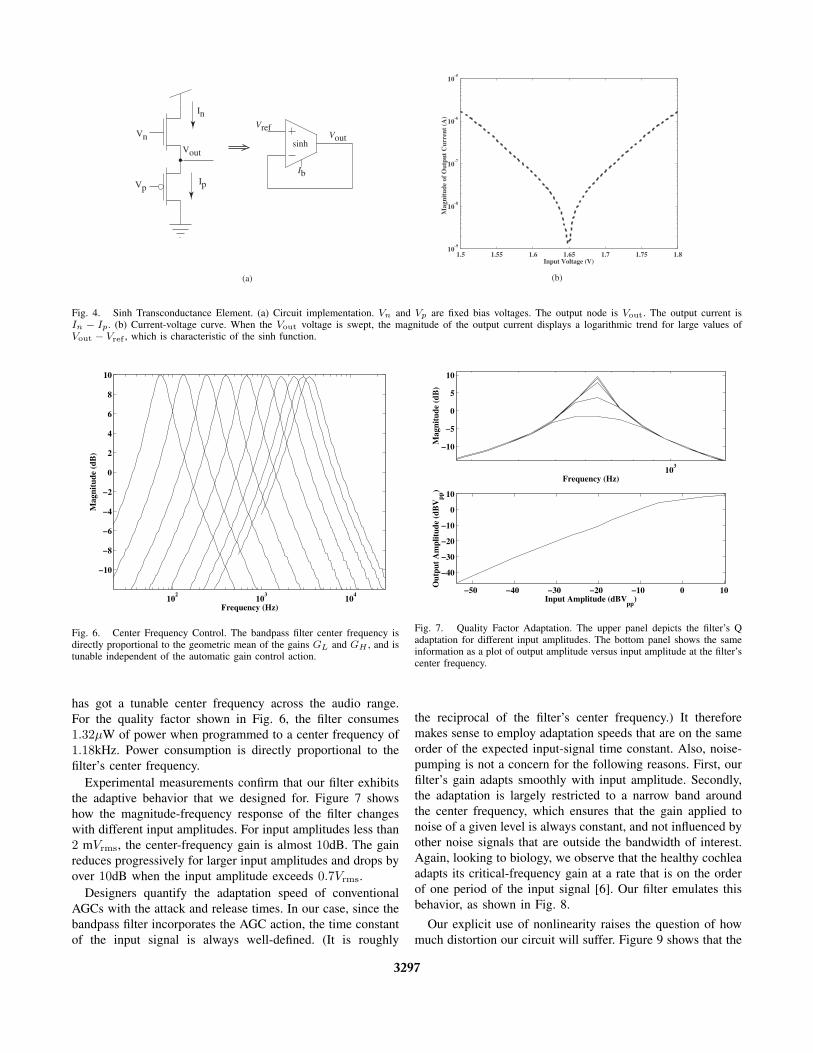
The transistors are biased with voltages Vn and Vp to ensuresubthreshold operation. In this case, large values of Vout
shut off the nMOS and elicit a positive exponential currentresponse from the pMOS. Similarly, small values of Vout elicita negative exponential current-voltage characteristic from thenMOS. The behavior of this circuit is identical to that of asinh, and we write its output current as
In − Ip = IN sinh ((Vout − Vref)/UT) ,
≈ IN
UT
((Vout − Vref) + (Vout − Vref)3/6U2
T
)),
(6)
where IN is some programable current, and Vref is thereference voltage.
IV. EXPERIMENTAL RESULTS
We fabricated the AGC-inherent bandpass filter in a 0.5µmprocess available from MOSIS, Fig. 5. As the results of Fig. 6show, the circuit behaves as a bandpass as expected, and
3296
In
Vn
Vp
Vout
Ip
Ib
Vref
sinhVout
1.5 1.55 1.6 1.65 1.7 1.75 1.810
-9
10-8
10-7
10-6
10-5
Mag
nitu
de o
f O
utpu
t C
urre
nt (
A)
Input Voltage (V)
(a) (b)
Fig. 4. Sinh Transconductance Element. (a) Circuit implementation. Vn and Vp are fixed bias voltages. The output node is Vout. The output current isIn − Ip. (b) Current-voltage curve. When the Vout voltage is swept, the magnitude of the output current displays a logarithmic trend for large values ofVout − Vref , which is characteristic of the sinh function.
102
103
104
−10
−8
−6
−4
−2
0
2
4
6
8
10
Frequency (Hz)
Mag
nitu
de (
dB)
Fig. 6. Center Frequency Control. The bandpass filter center frequency isdirectly proportional to the geometric mean of the gains GL and GH , and istunable independent of the automatic gain control action.
has got a tunable center frequency across the audio range.For the quality factor shown in Fig. 6, the filter consumes1.32µW of power when programmed to a center frequency of1.18kHz. Power consumption is directly proportional to thefilter’s center frequency.
Experimental measurements confirm that our filter exhibitsthe adaptive behavior that we designed for. Figure 7 showshow the magnitude-frequency response of the filter changeswith different input amplitudes. For input amplitudes less than2 mVrms, the center-frequency gain is almost 10dB. The gainreduces progressively for larger input amplitudes and drops byover 10dB when the input amplitude exceeds 0.7Vrms.
Designers quantify the adaptation speed of conventionalAGCs with the attack and release times. In our case, since thebandpass filter incorporates the AGC action, the time constantof the input signal is always well-defined. (It is roughly
103
−10
−5
0
5
10
Frequency (Hz)
Mag
nitu
de (
dB)
−50 −40 −30 −20 −10 0 10
−40
−30
−20
−10
0
10
Input Amplitude (dBVpp
)
Out
put
Am
plit
ude
(dB
Vpp
)
Fig. 7. Quality Factor Adaptation. The upper panel depicts the filter’s Qadaptation for different input amplitudes. The bottom panel shows the sameinformation as a plot of output amplitude versus input amplitude at the filter’scenter frequency.
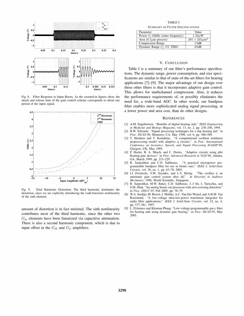
the reciprocal of the filter’s center frequency.) It thereforemakes sense to employ adaptation speeds that are on the sameorder of the expected input-signal time constant. Also, noise-pumping is not a concern for the following reasons. First, ourfilter’s gain adapts smoothly with input amplitude. Secondly,the adaptation is largely restricted to a narrow band aroundthe center frequency, which ensures that the gain applied tonoise of a given level is always constant, and not influenced byother noise signals that are outside the bandwidth of interest.Again, looking to biology, we observe that the healthy cochleaadapts its critical-frequency gain at a rate that is on the orderof one period of the input signal [6]. Our filter emulates thisbehavior, as shown in Fig. 8.
Our explicit use of nonlinearity raises the question of howmuch distortion our circuit will suffer. Figure 9 shows that the
3297
0.05 0.1 0.15 0.2 0.25 0.3 0.35 0.4
−1
−0.5
0
0.5
1
time(s)
Vol
tage
(V
)
Vin
Vout
0.09 0.1 0.11
−1
−0.5
0
0.5
1
time(s)
Vol
tage
(V
)
0.3 0.305 0.31 0.315
−1
−0.5
0
0.5
1
time(s)
Vol
tage
(V
)
Fig. 8. Filter Response to Input Bursts. As the zoomed-in figures show, theattack and release time of the gain control scheme corresponds to about oneperiod of the input signal.
−15 −10 −5 0 5 10 150
0.5
1
1.5
2
2.5
3
3.5
4
4.5
Input Amplitude (dBVpp
)
TH
D (
%)
2nd Harmonic3rd HarmonicTHD
Fig. 9. Total Harmonic Distortion. The third harmonic dominates thedistortion, since we are explicitly introducing the (odd-function) nonlinearityof the sinh element.
amount of distortion is in fact minimal. The sinh nonlinearitycontributes most of the third harmonic, since the other twoGm elements have been linearized via capacitive attenuation.There is also a second harmonic component, which is due toinput offset in the GH and GL amplifiers.
TABLE I
SUMMARY OF FILTER SPECIFICATIONS
Parameter ValuePower (1.18kHz center frequency) 1.32µWArea (0.5µm process) 285 × 245µm2
Compression Range 15dBDynamic Range (≤ 5% THD) 65dB
V. CONCLUSION
Table I is a summary of our filter’s performance specifica-tions. The dynamic range, power consumption, and size speci-fications are similar to that of state-of-the-art filters for hearingapplications [7]–[9]. The major advantage of our design overthese other filters is that it incorporates adaptive gain control.This allows for multichannel compression. Also, it reducesthe performance requirements of, or possibly eliminates theneed for, a wide-band AGC. In other words, our bandpassfilter enables more sophisticated analog signal processing, ata lower power and area cost, than do other designs.
REFERENCES
[1] A.M. Engebretson, “Benefits of digital hearing aids,” IEEE Engineeringin Medicine and Biology Magazine, vol. 13, no. 2, pp. 238–248, 1994.
[2] B.W. Edwards, “Signal processing techniques for a dsp hearing aid,” inProc. ISCAS‘98, Monterey, CA, May 1998, vol. 6, pp. 586–589.
[3] T. Hirahara and T. Komakine, “A computational cochlear nonlinearpreprocessing model with adaptive q circuits,” in Proc. InternationalConference on Acoustics, Speech, and Signal Processing ICASSP‘89,Glasgow, UK, May 1989.
[4] P. Hasler, B. A. Minch, and C. Diorio, “Adaptive circuits using pfetfloating-gate devices,” in Proc. Advanced Research in VLSI’99, Atlanta,GA, March 1999, pp. 215–229.
[5] R. Sarpeshkar and C.D. Salthouse, “A practical micropower pro-grammable bandpass filter for use in bionic ears,” IEEE J. Solid-StateCircuits, vol. 38, no. 1, pp. 63–70, 2003.
[6] J.J Zwislocki, Y.M. Szymko, and L.Y. Hertig, “The cochlea is anautomatic gain control system after all,” in Diversity in AuditoryMechanics. 1996, World Scientific, Singapore.
[7] R. Sarpeshkar, M.W. Baker, C.D. Salthouse, J.-J Sit, L Turicchia, andS.M. Zhak, “An analog bionic ear processor with zero-crossing detection,”in Proc. ISSCC’05, Feb 2005, pp. 78–79.
[8] W.A. Serdijn, M. Broest, J. Mulder, A.C. Van Der Woerd, and A.H.M. VanRoermund, “A low-voltage ultra-low-power translinear integrator foraudio filter applications,” IEEE J. Solid-State Circuits, vol. 32, no. 4,pp. 577–581, 1997.
[9] L. Pylarinos and Khoman Phang, “Low-voltage programmable gm-c filterfor hearing aids using dynamic gate biasing,” in Proc. ISCAS’05, May2005.
3298