An absolute determination of the acceleration of gravity
70
Transcript of An absolute determination of the acceleration of gravity

THE UNIVERSITY
OF ILLINOIS
LIBRARY
015?&5

The person charging this material is re-
sponsible for its return to the library fromwhich it was withdrawn on or before the
Latest Date stamped below.
Theft/ mutilation, and underlining of books are reasons
for disciplinary action and may result in dismissal from
the University.
To renew call Telephone Center, 333-8400
UNIVERSITY OF ILLINOIS LIBRARY AT URBANA-CHAMPAIGN
JUL i
L161—O-1046
. 9£ \ •< SkiV^y's !J» ^Mb'j:


AN ABSOLUTE DETERMINATION OF THE
ACCELERATION OF GRAVITY
BY
LESLIE ARTHUR PINKNEY
A. B. Wheaton College, 1910
THESIS
Submitted in Partial Fulfillment of the Requirements for the
Degree of
MASTER OF ARTS
IN PHYSICS
IN
THE GRADUATE SCHOOL
OF THE
UNIVERSITY OF ILLINOIS
1915

Digitized by the Internet Archive
in 2013
http://archive.org/details/absolutedeterminOOpink
HIS
fc6
UNIVERSITY OF ILLINOIS
THE GRADUATE SCHOOL
May 29 19(Jo
1 HEREBY RECOMMEND THAT THE THESIS PREPARED UNDER MY SUPERVISION BY
LESLIE ARTHUR PINKNEY
ENTITLED AN ABSOLUTE DETERMINATION OF. THE ACCELERATION OF
GRAVITY
BE ACCEPTED AS FULFILLING THIS PART OF THE REQUIREMENTS FOR THE
DEGREE OF MASTER OF ARTS IN PHYSICS
Head of Department
Recommendation concurred in:
Committee
on
Final Examination

IR)C

H\5
CONTENTS
I. Historical 1
II. Theoretical 3
III. Description of Apparatus 9
IV. Measurement of Distance between Knife-edges 15
V. Measurement of the Period 17
VI. Corrections 23
VII, Calculation of w g" 35
VIII. Discussion 26
318978

I. HISTORICAL
For the absolute determination of the acceleration
of gravity ("g"), the compound reversible pendulum is usually em-
ployed. This was first used by Captain Kater in 1817, who was
commissioned by the Royal Society of London to determine accurate-
ly the length of a seconds pendulum at Greenwich^" In the con-
struction of the pendulum, he made the first practical application
of the theory of reversibility of the centers of suspension and
oscillation that had been worked out in 1673 by Huyghens. By de-
termining the period with the method of coincidences, which was
used first by Bouguer in 1737, Kater succeeded in establishing a
2standard method for determining "g". Later in 1826, Bessel, using
a wire suspended pendulum, made extensive experiments in which he
considerably modified the air corrections.
In this country the most extensive work done along
this line was carried on under the supervision of the United States
Coast and Geodetic Survey. The work of the Survey began about
1873 and extended over a number of years. Gravity determinations
were made at several stations thruout the country. These were
only differential or relative determinations based on the absolute
value at Washington the base station. This absolute value was ob-
tained from several independent determinations, one by Peirce at
Hoboken using the Repsold reversible pendulum, and another by Her-
1. Poynting and Thomson, "Properties of Matter", p. 12
Phil. Trans, for 1818 and 1819.
2. Ostwald, "Klass. der Exak. Wissen." , Vol. 7, 1889.

3
schel at Washington using the Kater reversible pendulum^ The mean
of these results gave for the absolute value at Washington 980.10o
cm/sec, which was used as the basis for the relative work at the
other stations.
The purpose of this work is to determine the abso-
lute value of the acceleration of gravity in room 116 on the first
floor of the Laboratory of Physics at the University of Illinois.
A Kater 1 s pendulum is swung in a receiver from which the air is
exhausted. In this way the period of the pendulum may be obtained
independent of the effects of the air, thus giving an absolute
value of "g".
1. United States Coast and Geodetic Survey Report, 1891, Par t II.

I

3
II. THEORETICAL
Kater's compound reversible pendulum is based di-
rectly on Huyghens' principle that the centers of oscillation
and suspension are interchangeable, and that the distance be-
tween the two is equal to the length of
an equivalent simple pendulum, A brief
theoretical treatment of this will now
be considered.
Let any irregular body be
capable of rotation about an axis pass-
ing thru the point C, the center of sus-
pension. Let w be the angular velocity
of any little particle P at a distance r
from the axis C. Then
Figure 1 wr = linear velocity of P.
Since acceleration is the derivative of the velocity with re-
spect to the time,
dwr — = linear acceleration of P.
dt
If m is the mass of the particle P, then the force acting on P
at right angles to r is, since F = ma,
dwF = mr ~*~
dt
The moment of this force about the axis thru C is
2 dwmr —
dt

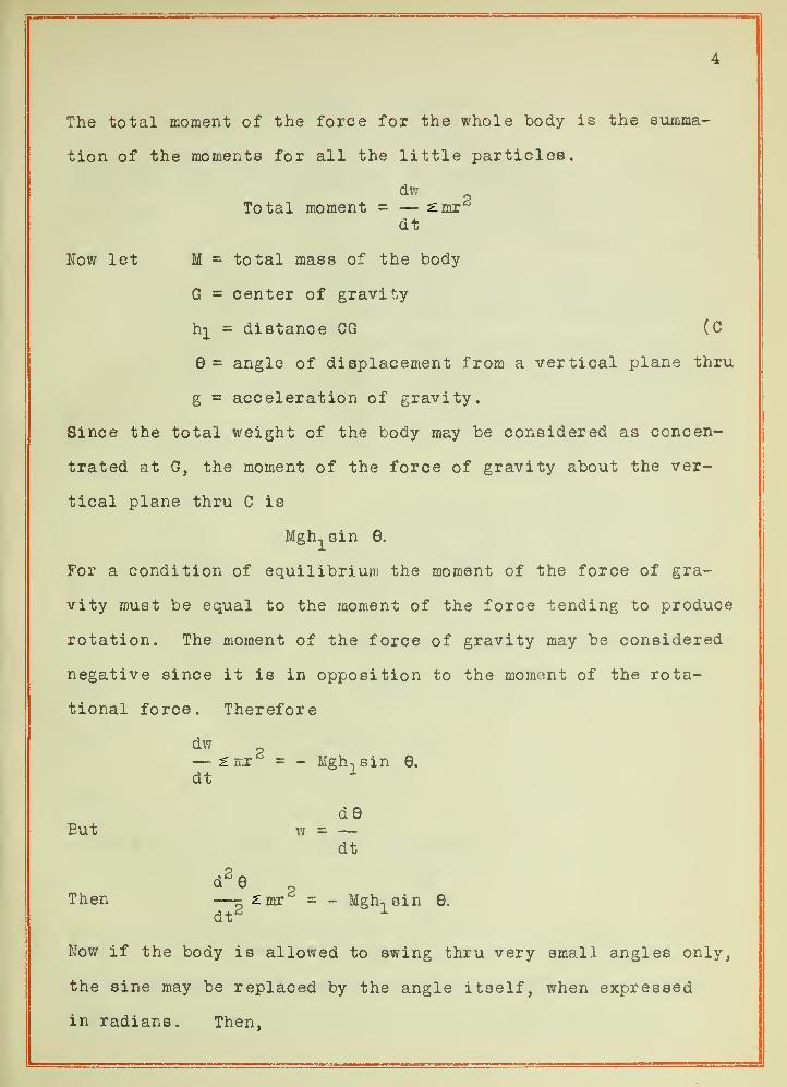
4
The total moment of the force for the whole body is the summa-
tion of the moments for all the little particles.
dwTotal moment = — ^mr*5
dt
Nov/ let M = total mass of the body
G = center of gravity
hi = distance GG (C
8 = angle of displacement from a vertical plane thru
g = acceleration of gravity.
Since the total weight of the body may be considered as concen-
trated at G, the moment of the force of gravity about the ver-
tical plane thru C is
Mgh^sin 6.
For a condition of equilibrium the moment of the force of gra-
vity must be equal to the moment of the force lending to produce
rotation. The moment of the force of gravity may be considered
negative since it is in opposition to the moment of the rota-
tional force. Therefore
dw— £ mr = - Mgh. sin 6.
dt1
d9But w = —
dt
d26
Then5£mr^ = - Mgh-, sin 6.
dt'
Now if the body is allowed to swing thru very small angles only,
the sine may be replaced by the angle itself, when expressed
in radians. Then,


d e Mgh.e. (i)
dt ^mr*
This means that the acceleration is proportional to the dis-
placement and the point P will describe a simple harmonic motion.
Now let the point P be con-
sidered as moving in the circle of
reference which is the projection of
the simple harmonic motion. (Fig. 2)
Its acceleration toward the center is
given by the usual formula,
va = -
r
2
Figure 2
But the desired acceleration is that
toward the center along AO = x. Re-
solving the acceleration along PO,
,2v
r
V Xax = -- cos 6 = -
But
Then
Also
w 2r2x
ax = '5
wr
= -w2x.
2tt
w =
where T is the periodic time. Therefore
24tt'
ax = -
that is the acceleration toward the center is proportional to
the displacement. This is the corresponding condition for the
compound pendulum that is stated in equation (1). Then the


6
constants must be equal, or
4tt2 Mghn
T2 2mr2
From this the period of vibration of the pendulum about C is
ViTx
= 2tt (2)VMghx
where zmr2 = I, which is the moment of inertia.
Now let the body be rotated about the center of os-
cillation (Fig. 1) distant hg from G and in the same plane as
C and G. In the same manner as above the period may be shown
to be,
T2
= 2tt (3)VMgh2
Let IQ be the moment of inertia of the body about
its center of gravity. Then by a well known principle in Me-
chanics, ths moment of inertia about the point C is,
I = I + Mh2
Substituting this in equation (2),
V(I + Mh?) ViT1
= 2tt i- = 2tt —VMgh
1 Vg
for there is some simple pendulum of length 1 whose period is
the same as that of the compound pendulum under consideration.
Therefore,
Ip Mh3
! _
Mh1
2In this equation IQ may be replaced by MR , where R is the
radius of gyration. Then,

R2 + h? R2
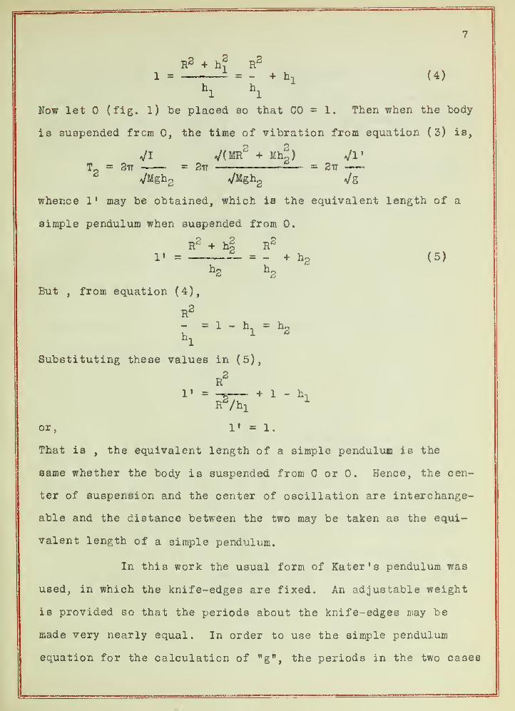
1 = = - + h, (4)hl
hl
Now let (fig. 1) be placed so that CO = 1. Then when the body
is suspended from 0, the time of vibration from equation (3) is,
VI V(MR2
+ Mhg) VI
'
Tp = Stt = 2tt = 2tt
* VMgh2 VMgh2 Vg
whence 1* may be obtained, which is the equivalent length of a
simple pendulum when suspended from 0.
R° + ho Rfi
1« = — = - + h2 (5)
But , from equation (4),
R2
- = 1 - h = h~h, * 2
Substituting these values in (5),
R2
1' = -~ + 1 " hn
or, 1« m l.
That is , the equivalent length of a simple pendulum is the
same whether the body is suspended from C or 0. Hence, the cen-
ter of suspension and the center of oscillation are interchange-
able and the distance between the two may be taken as the equi-
valent length of a simple pendulum.
In this work the usual form of Kater's pendulum was
used, in which the knife-edges are fixed. An adjustable weight
is provided so that the periods about the knife-edges may be
made very nearly equal. In order to use the simple pendulum
equation for the calculation of "g", the periods in the two cases

t
T
I
r

8
would have to be exactly equal. The adjustment to equality is
a task requiring some patience and time. Instead, Bessel intro-
duced the following modification so that it is necessary for the
periods to be only approximately equal,
? 2From equation (2), remembering that I = MR^ * MhJ ,
and taking the period for a single vibration,
t-i = TT
V(R2 + hf)
In the same way from equation (3),
t = TT
2Eliminating R from these two equations, the final formula for
the calculation of MgM is obtained,
3 2 2tt - h
2t2
g \ - h2
2+ t
2t2
t2
= J: L_ + _3 2_ (6)2(hx + h
2 )2(h
x- h
2 )
Since the periods are very nearly equal, the difference of their
squares is very small, so that the value of the second fraction
in (6) is very small. Hence it is necessary to know (h-^ - h2 )
only approximately. The position of the center of gravity is
readily determined by balancing the pendulum, then h-^ and hg
can be measured with a meter stick. The quantities that must be
measured with great precision are (h-^ + h2 ) = 1 and t^ and t
2 .
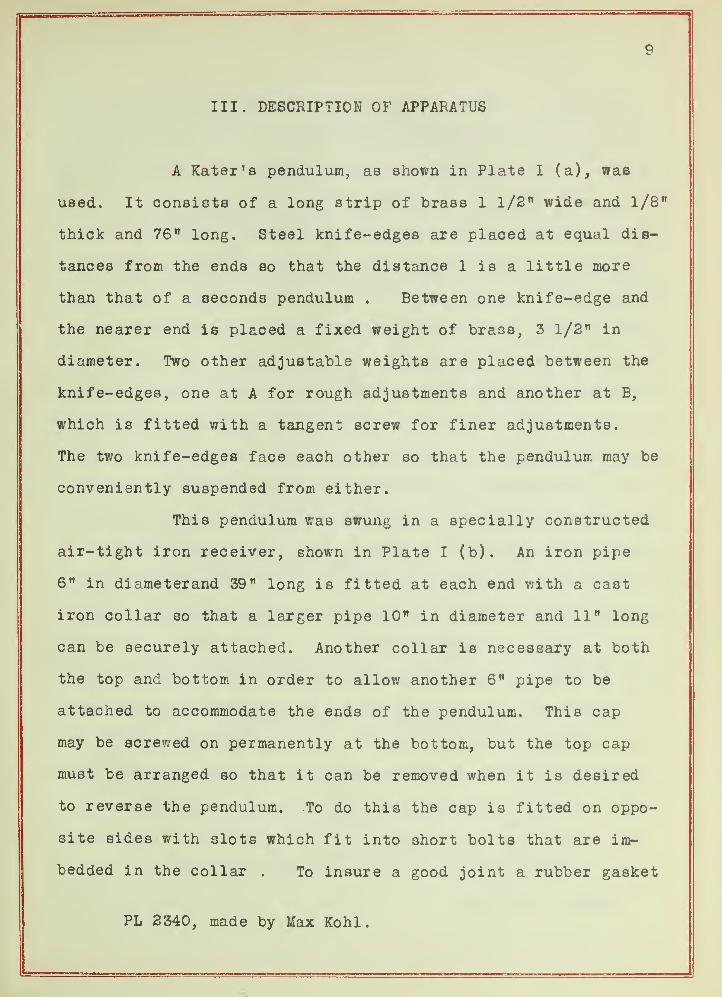
III. DESCRIPTION OF APPARATUS
A Kater's pendulum, as shown in Plate I (a), was
used. It consists of a long strip of brass 1 1/2" wide and 1/8"
thick and 76" long. Steel knife-edges are placed at equal dis-
tances from the ends so that the distance 1 is a little more
than that of a seconds pendulum . Between one knife-edge and
the nearer end is placed a fixed weight of brass, 3 1/2" in
diameter. Two other adjustable weights are placed between the
knife-edges, one at A for rough adjustments and another at B,
which is fitted with a tangent screw for finer adjustments.
The two knife-edges face each other so that the pendulum may be
conveniently suspended from either.
This pendulum was swung in a specially constructed
air-tight iron receiver, shown in Plate I (b). An iron pipe
6" in diameterand 39" long is fitted at each end with a cast
iron collar so that a larger pipe 10" in diameter and 11" long
can be securely attached. Another collar is necessary at both
the top and bottom in order to allow another 6" pipe to be
attached to accommodate the ends of the pendulum. This cap
may be screwed on permanently at the bottom, but the top cap
must be arranged so that it can be removed when it is desired
to reverse the pendulum. To do this the cap is fitted on oppo-
site sides with slots which fit into short bolts that are im-
bedded in the collar . To insure a good joint a rubber gasket
PL 2340, made by Max Kohl.
10
is placed over the bearing surface on the collar. Then to re-
move the cap it is only necessary to take off the nuts at nn.
The knife-edges are supported by an 8 M plate in which is cut a
5/8" slot as shown in (c). The position of this plate in the re-
ceiver is shown by the dotted lines. The plate is held in place
by a small pin which readily slips thru the hole at e into an-
other hole drilled for the purpose in the collar. For observing
the swinging pendulum, four windows are provided, two in front
as shown in the figure and two in the rear. To provide a plane
bearing surface for the glass, brass strips are cut and soldered
to the rounding surface of the pipe. In order to withstand the
pressure, the pieces of glass used were one inch in thickness.
The glass is held to the bearing surface by clamps which are
tightened by nuts which turn on small bolts imbedded in the pipe.
By turning the plate already referred to thru 90°, it is possible
to have the pendulum swing in a plane parallel or perpendicular
to the plane of the windows. To set the pendulum swinging, after
the air has been pumped out, it is held aside by a small fuse
wire attached to two binding posts bb, which are carefully insu-
lated from the receiver. The pendulum may then be started at
any time by blowing the fuse. The air is exhausted with an air
pump^thru a stopcock S. The pressure is measured by attaching a
closed short-arm manometer filled with mercury to another stop-
cock at S ' .
The firm support of this receiver is a matter of con-
siderable importance. A plank seven feet long was fastened by
1. PL 3576, Gaede rotary pump, E. Leybold ! e Nachfolger.

11
long expansion bolts to a solid brick wall. To the plank was
bolted a heavy cast iron wall-bracket. The receiver is then sus-
pended from this bracket, the ends of which are shown at cc. In
this way a very rigid support was provided for the swinging pen-
dulum. For convenience a much lighter support was provided for
swinging the pendulum in the open air. This was done so that the
periods about the two knife-edges could be readily adjusted to ap-
proximate equality before the pendulum was placed in the receiver.
In measuring the period, the optical coincidence
method, to be described later, was employed. This requires two
mirrors, one fixed and the other moving with the pendulum. The
movable mirrors are stuck to the pendulum with a small piece of
wax at m and m 1. When the pendulum is swinging with the weight
down m is used for observation, and when the weight is up m 1 is
used. The fixed mirror must be supported very near to the moving
one and yet not interfere with the motion of the pendulum. It must
also be arranged so that, when the pendulum is at rest, the two
images of a spark may be adjusted to exact coincidence in the field
of an observing telescope. To do this the support shown in (d) is
employed. This is constructed so that it will rest conveniently
at one side of the pendulum on the shelf formed by the collar in
the part of the receiver. It consists of an iron base to
one end of which is attached a short upright piece. To this piece
is fastened an iron strip carrying a thumbscrew s. A second and
thinner strip is fastened just above so that one end rests on the
thumbscrew and the other is screwed to the top of the upright
piece. The mirror is then waxed to another upright piece at p,

12
which projects out over the base as shown in the end view. By
turning the thumbscrew, the mirror may be adjusted vertically, and
by moving the whole support , it may be adjusted horizontally. In
this way the two images may be brought to exact coincidence when
the pendulum is at rest.
In order to keep the receiver from leaking, it was
found necessary to go over all the joints with half-and-half wax.
This is a mixture of half resin and half beeswax melted together
and is applied with a brush when hot. The windows were seated in
universal wax. This was found more convenient because the lower
window must be removed each time a series of coincidences is ob-
served. The whole surface of the receiver was treated with a spe-
cial iron filler and then painted . With these precautions, the
pressure could be kept constant at 1.5 cm. When the pump was
turned off, the leakage was so small that the pressure remained
the same for several hours.
After completing the work, it was found that several
alterations in the receiver could be profitably made. The two
rear windows are unnecessary. Another smaller window should be
provided 90° around to the side of the lower front window. This
should be so placed that the lower knife-edge may be readily ob-
served thru it. In this way the amplitude of vibration may be
measured accurately with an observing telescope on a scale. The
distance between the knife-edges may be taken as the distance to
the scale, thus allowing an accurate calculation of the correction
for arc
.
In the plate supporting the knife-edges should be
13
placed an insert of hardened steel or preferably agate. It was
found that the knife-edges made a slight impression in the iron
thus considerably increasing the friction of support.were-
The binding posts for the fuse wire^found to be un-
necessary. It was possible to set the pendulum swinging with the
hand, seat the window in the wax and exhaust the receiver to a
constant pressure in about twenty minutes. Ample time remains to
take the observations since the pendulum continues to swing thru
a sufficient amplitude for about three hours.

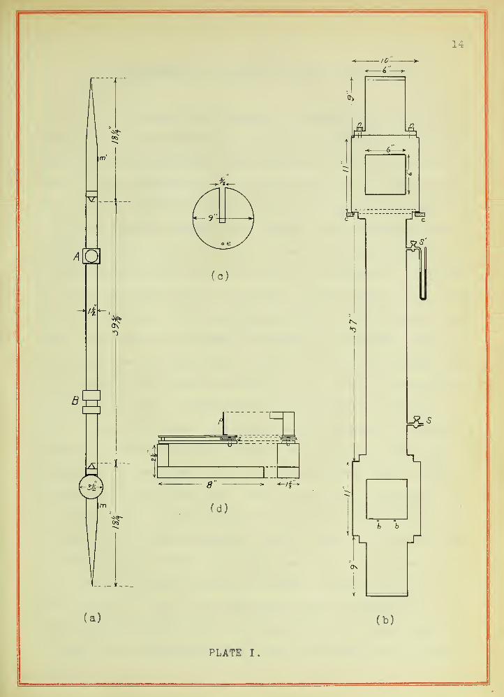
PLATE I.

15
IV. MEASUREMENT OF DISTANCE BETWEEN KNIFE-EDGES
To measure the length 1, a cathetometer resting on a
heavy pier and provided with two reading telescopes was employed.
The pendulum was suspended from a supporting frame immediately in
front of the cathetometer. A standard meter bar of invar, correct
at 0° C, was supported alongside the pendulum, being adjusted to
a vertical position by means of a level. The cathetometer was
adjusted so that the optical axis of each telescope was parallel
with the axis of its level, and so that, by turning in a horizon-
tal plane the level was not disturbed. In the field of each tele-
scope, in addition to ths usual cross-hairs, is a horizontal hair
which can be moved up and down by turning a micrometer screw. By
sighting on the standard bar, a constant K can be determined for
each telescope, which may be defined as the number of centimeters
thru which the hair is advanced when the micrometer screw is
turned thru one division. To determine K an average of several
trials was taken as the final value. The telescopes were then
sighted on the pendulum, each hair being adjusted until it just
coincided with the knife-edge. Then, turning the telescopes on
the standard bar, it was observed thru how many divisions it was
necessary to turn the micrometer screw in order to bring the hair
to a division on the bar. By making use of K, the distance be-
tween the knife-edges is readily obtained. Since the bar is a
meter long at 0° only, the temperature must be observed and a cor-
rection applied making use of the coefficient of linear expansion
of invar. The accompanying table shows the results of the meas-
urement.

16
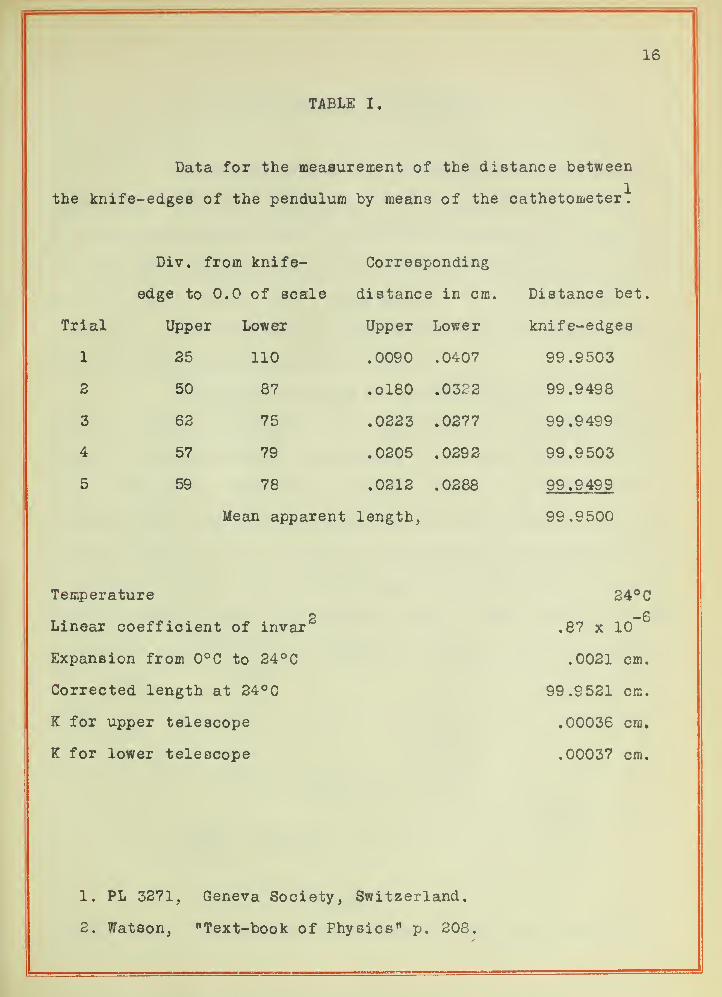
TABLE I.
Data for the measurement of the distance between
the knife-edges of the pendulum by means of the cathetometer^
Trial
1
2
3
4
5
Div. from knife-
edge to 0.0 of scale
Upper Lower
25
50
62
57
59
110
87
75
79
78
Corresponding
distance in cm,
Upper Lower
.0090 .0407
.0180 .0322
.0223 .0277
.0205 .0292
.0212 .0288
Mean apparent length,
Distance bet.
knife-edges
99.9503
99.9498
99.9499
99.9503
99.9499
99.9500
Temperature<
Linear coefficient of invar'
Expansion from 0°0 to 24°C
Corrected length at 24°C
K for upper telescope
K for lower telescope
24°C
.87 x 10"6
.0021 cm.
99.9521 cm.
.00036 cm.
.00037 cm.
1. PL 3271, Geneva Society, Switzerland,
2. Watson, "Text-book of Physics 11 p. 208.

17
V. MEASUREMENT OF THE PERIOD
The measurement of the period must be taken with ex-
treme care, since any error made in this enters as the squares
into the calculation of "g". As already described, the pendulum
is swung in a receiver from which the air is exhausted to a pres-
sure of 1,5 cm. of mercury. The period of the pendulum while
swinging in the receiver was compared to that of a standard astro-
nomical clock made by Riefler of Munich.
The method used was the optical method of coinci-
dences. This is essentially the method used by the United States
Coast and Geodetic Survey but adapted to the conditions of this
work. Within the works of the standard clock is a device which
automatically breaks an electrical circuit each second. This cir-
cuit is connected thru a relay to the primary of an induction coiL
By short-circuiting the automatic make-and-break of the coil, the
relay is made to break the primary circuit. Thus the clock causes
a spark to pass between the secondary terminals once each second.
Co//Clock
Figure 3
Figure 3 shows the method of connection. One storage cell is

18
used in the clock circuit and five or six with a rheostat are used
in the relay circuit. In order to reduce the amount of sparking
of the relay to a minimum a condenser is connected as shown.
The image of the spark that i3 thus produced is re-
flected into the field of an observing telescope by two mirrors,
one fixed and the other movable. The movable mirror is placed on
the pendulum and the fixed mirror is firmly supported as near to
the movable one as possible without interfering with the motion
of the pendulum. These two mirrors are so adjusted that, when the
pendulum is hanging freely at rest, the two images of the spark
appear as one in the field of the telescope. When the pendulum
is set swinging the images are separated and gradually become far-
ther and farther apart as the pendulum loses on the clock. The
movable image finally goes out of the field altogether but soon
reappears as the next coincidence is approached. At the instant
the spark passes and only one image is seen, the hour, minute and
second as noted on the clock are recorded. The time of the first
three and last three of a series of twelve coincidences is noted.
Then the time for any desired interval i3 calculated, for instance
the interval between the first and tenth or second and twelfth
coincidence. Since the pendulum is slightly slower than the clock,
one single vibration is lost during the time between two coinci-
dences. Thus between the second and twelfth coincidences the pen-
dulum makes ten less single vibrations than the number of seconds
indicated by the clock. From this the period of the pendulum is
readily obtained. With careful observation this method gives an
accuracy of more than one part in a million.
19
The following tables show the results of the obser-
vations. Tables II and III give the data for determining t-, and
tg. For purposes of comparison, table IV is given to show the
results obtained when the pendulum is swinging at atmospheric
pressure

20
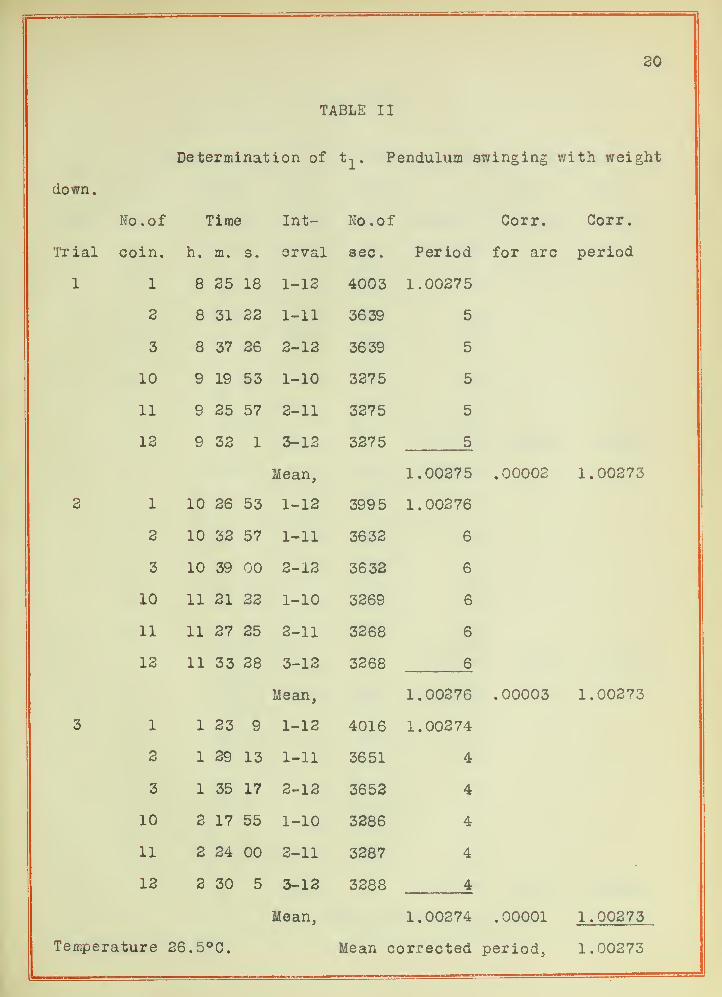
TABLE II
Determination of t-^. Pendulum swinging with weight
down.
No. of Time Int- No. of Corr. Corr.
Tr ial coin. n. m. 3
.
erval sec. Period for arc period
1 1 Qo P R lo 1-12 4003 1.00275
2 cO ^101 1-11 3639 5
3 oo O ( PA 2-12 3639 5
10 Q TOlb OO 1-10 3375 5
11 o PR R7O f 2-11 3375 5
12 9 32 1 3-12
Mean,
3375 5
1.00375 .00002 1.00273
2 1 i n JO 1-12 399 5 1.00276
2 1 oIU *^P R7O f 1-11 3632 6
3 1 o1U uu 2-13 3633 6
10 1 X PI<5X pp 1-10 3369 6
11 P7 PR 3-11 3368 6
12 11 33 28 3-13
Mean,
3368 6
1.00276 .00003 1.00273
3 1 1 23 g 1-12 4016 1.00274
2 1 29 13 1-11 3651 4
3 1 35 17 2-13 3653 4
10 2 17 55 1-10 3386 4
11 2 24 00 3-11 3387 4
13 2 30 5 3-13
Mean,
3388 4
1.00274 .00001 1.00273
Temperature 26.5°C. Mean corrected period, 1.00273

21
TABLE III
Determination of t n . Pendulum swinging with weight up,
No. of Time In- No.of Cor r
.
Corr
.
Trial coin. h. m. 8. terval sec
.
Period
1 1 1 56 22 1-12 4302 1.00256
2 2 2 53 1-11 3910 6
3 2 9 24 2-13 3911 6
10 2 no 1-10 3518 6
11 3 iX 2-11 3519 6
12 3 QO A*± 3-12
Mean,
3520 6
1.00256
2 1 3 7S 1-12 4312 1.00255
2 3 5 1-11 3920 5
3 3 49 36 2-12 3933 5
10 4 35 21 1-10 3526 5
11 4 41 55 2-11 3530 5
12 4 48 27 3-12
Mean,
3531 5
1.00255
3 1 7 27 49 1-12 4297 1.00256
2 7 34 18 1-11 3905 6
3 7 40 48 2-12 3908 6
10 8 26 23 1-10 3514 6
11 8 32 54 2-11 3516 6
12 8 39 26 3-12
Mean,
3518 6
1.00256
1.00253
1.00253
1.00253
Mean corrected period, 1.00253
Temperature 26.5°C.
22
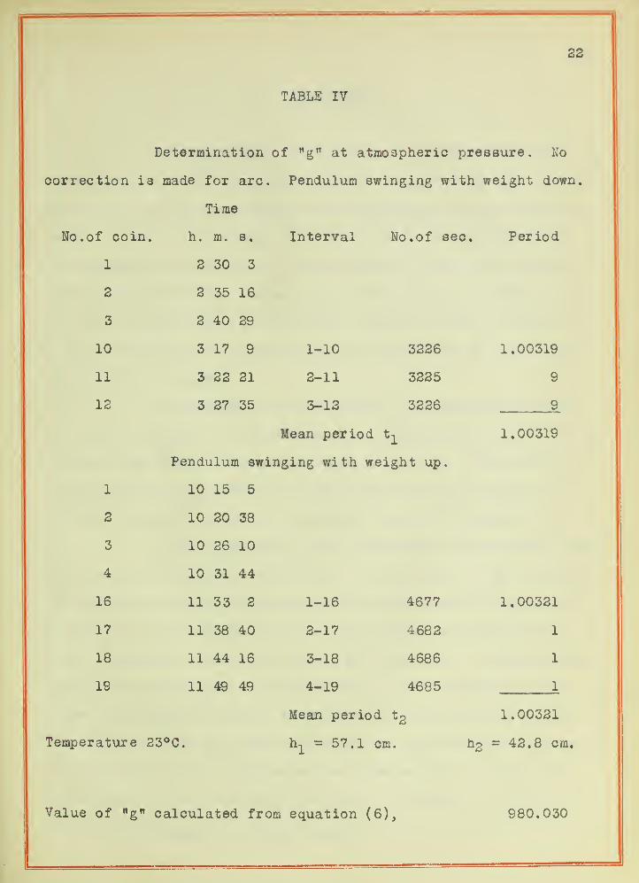
TABLE IV
Determination of "g" at atmospheric pressure. No
correction is made for arc. Pendulum swinging with weight down.
Time
f coin. h. m. 8. Interval No. of sec. Per iod
1 2 30 3
2 2 35 16
3 2 40 29
10 3 17 9 1-10 3226 1.00319
11 3 22 21 2-11 3225 9
12 3 27 35 3-12 3226 9
Mean period 1.00319
Pendulum swinging with weight up.
1 10 15 5
2 10 20 38
3 10 26 10
4 10 31 44
16 11 33 2 1-16 4677 1.00321
17 11 38 40 2-17 4682 1
18 11 44 16 3-18 4686 1
19 11 49 49 4-19 4685 1
Mean period to 1.00321
Temperature 23°C. h, = 57.1 cm. h2 = 42.8 cm.
Value of "g w calculated from equation (6), 980.030

23
VI. CORRECTIONS
1. Temperature . The work of the experiment was car-
ried on in an "even- temperature room". It was found that during
the taking of the observations the temperature did not vary more
than .2°, which is so small as to introduce a negligible error.
The temperature however was not the same as that of the room in
which the cathetometer measurement of the length was made. This
of course necessitates a correction, which is readily made by no-
ting the difference in temperature and making use of the linear
coefficient of brass.
2. Pressure . By keeping the air pump in operation
during the progress of an observation, the pressure in the recei-
ver was kept down to a constant value of 1.5 cm. The period at
this pressure will differ but very little from the period in a
perfect vacuum} so that no correction is made for pressure.
3. Arc correction. The correction to infinitely small
arcs is of considerable importance. To make this it is necessary
to know the amount of displacement from the center in minutes of
arc both at the beginning and end of a series of observations. A
short centimeter scale is placed across the shelf in the enlarge-
ment of the lower part of the receiver. Its distance from the
upper knife-edge is readily determined by adding to the length 1,
the distance from the lower knife-edge to the surface of the scale?
The position of the pendulum may be observed when at rest, when
drawn aside at the beginning and again at the end of a series of
1. See page 26 of this thesis.

24
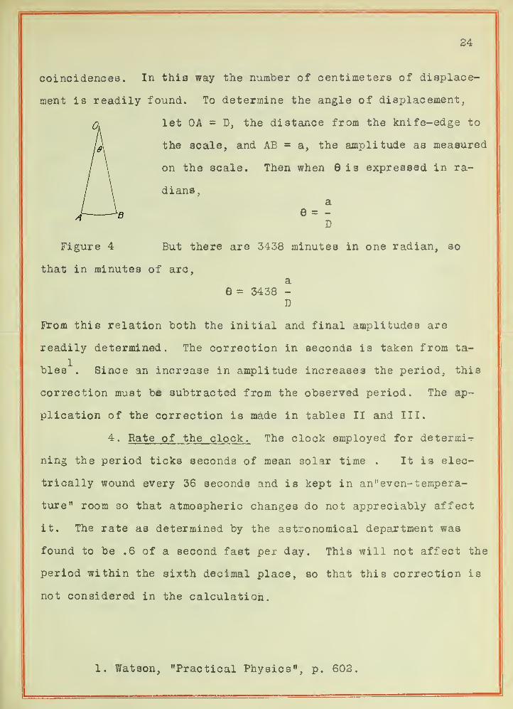
coincidences. In this way the number of centimeters of displace-
ment is readily found. To determine the angle of displacement.
let OA = D, the distance from the knife-edge to
the scale, and AB = a, the amplitude as measured
on the scale. Then when Sis expressed in ra-
dians,a
e = -
D
Figure 4 But there are 3438 minutes in one radian, so
that in minutes of arc,a
6 = 3438 -
D
From this relation both the initial and final amplitudes are
readily determined. The correction in seconds is taken from ta-
bles . Since an increase in amplitude increases the period, this
correction must be subtracted from the observed period. The ap-
plication of the correction is made in tables II and III.
4 - Rate of the clock. The clock employed for determi-r
ning the period ticks seconds of mean solar time . It is elec-
trically wound every 36 seconds and is kept in an" even- tempera-
ture" room so that atmospheric changes do not appreciably affect
it. The rate as determined by the astronomical department was
found to be .6 of a second fast per day. This will not affect the
period within the sixth decimal place, so that this correction is
not considered in the calculation.
1. Watson, "Practical Physics", p. 602.

25
VII. CALCULATION OF "g"
(a). From data obtained.
Mean corrected period t^ ,
Mean corrected period t,
Length 1 in cm. at 24°C,
Temperature of room during observations,
Linear coefficient of brass,
Length 1 at 36.5°C,
Distance h-^ in cm.,
Distance in cm.,
Value of w g"in cm. /sec. from equation (6),
1.00273
1,00253
99.9521
26.5°C
.187 x 10"4
99.9567
57.1
42.8
980.099 3
(b). From Smithsonian Physical Tables.
Formula given,
g^= S45(l -.002663 cos 2$
2h 3-(1 - -)R 4
where is the latitude, h the elevation above sea level, R the
radius of the earth, the surface density, the mean density of
the earth. The ratio - is very nearly 1/2. This gives a diminu-
tion in "g w Of .00588 cm. /sec. for each 100 feet of elevation.
Elevation of laboratory, 725 ft.
Latitude, 40° 6' 40"
Value of w g", 980.1141
Per cent difference in two results, .001
1. Smithsonian Physical Tables, p. 104.
26
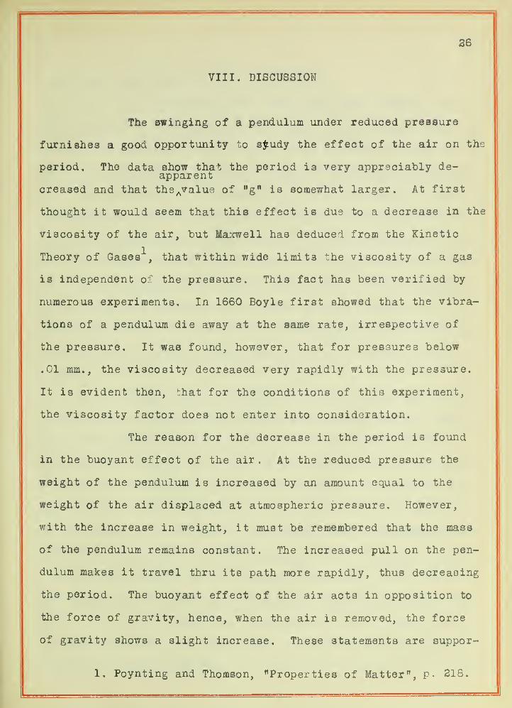
VIII. DISCUSSION
The swinging of a pendulum under reduced pressure
furnishes a good opportunity to sy-udy the effect of the air on the
period. The data show that the period i3 very appreciably de-apparent
creased and that the Avalue of "g" is somewhat larger. At first
thought it would seem that this effect is dus to a decrease in the
viscosity of the air, but Maxwell has deduced from the Kinetic
1Theory of Gases , that within wide limit3 the viscosity of a gas
is independent of the pressure. This fact has been verified by
numerous experiments. In 1660 Boyle first showed that the vibra-
tions of a pendulum die away at the same rate, irrespective of
the pressure. It was found, however, that for pressures below
.01 mm., the viscosity decreased very rapidly with the pressure.
It is evident then, that for the conditions of this experiment,
the viscosity factor does not enter into consideration.
The reason for the decrease in the period is found
in the buoyant effect of the air. At the reduced pressure the
weight of the pendulum is increased by an amount equal to the
weight of the air displaced at atmospheric pressure. However,
with the increase in weight, it must be remembered that the mass
of the pendulum remains constant. The increased pull on the pen-
dulum makes it travel thru its path more rapidly, thus decreasing
the period. The buoyant effect of the air acts in opposition to
the force of gravity, hence, when the air is removed, the force
of gravity shows a slight increase. These statements are suppor-
1. Poynting and Thomson, "Properties of Matter", p. 218.


37
ted by the experimental results obtained.
The accuracy of the final result was somewhat hin-
dered because no provision was made for a very accurate measure-
ment of the amplitude of vibration . The method used gives the
period with reasonable accuracy ou: to the seventh decimal place,
while the correction for arc appears in the fifth place. Since
the amplitude could not be measured to an accuracy greater than
one or two millimeters, a correction for the arc farther out than
the fifth place is hardly justifiable. For this reason the peri-
od was carried only to the fifth place thruout. Thi3 however,
gives the period correctly to six significant figures, and with
the measurement of the length also to six figures, it is reason-
able to believe that the final value for ng
n is correct to six
figures
.
For purposes of comparison, the value of ngn is also
computed from a formula given in the Smithsonian Physical Tables,
The establishment of this formula will not be considered here.
The absolute value of ngw at sea level and latitude 45° (980.600)
is taken as the basis, so that by substituting the elevation and
latitude for a given place the value of "g" is readily calculated.
The elevation of the laboratory was obtained from a benchmark es-
tablished by the United States Geological Survey, and the lati-
tude was furnished by the astronomical department. The formula
also depends on the ratio of the surface density to the mean den-
sity of the earth. This is a factor which is very likely subject
to local variation, and which would account for the slight dis-
crepancy in the two results.
28
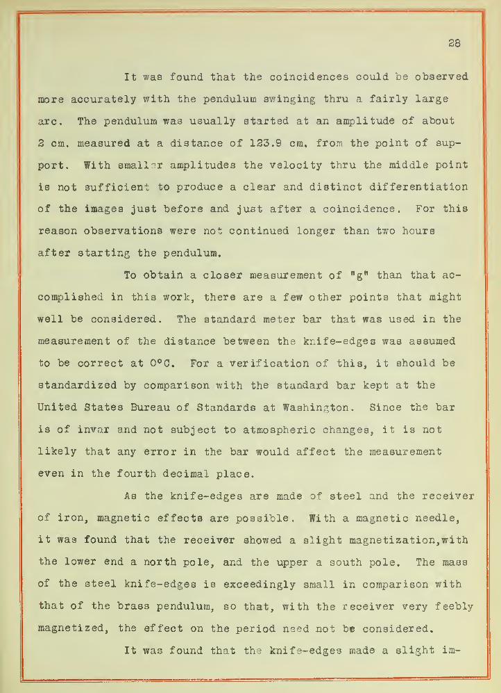
It was found that the coincidences could be observed
more accurately with the pendulum swinging thru a fairly large
arc. The pendulum wa3 usually started at an amplitude of about
2 cm. measured at a distance of 123.9 cm. from the point of sup-
port. With smaller amplitudes the velocity thru the middle point
is not sufficient to produce a clear and distinct differentiation
of the images just before and just after a coincidence. For this
reason observations were not continued longer than two hours
after starting the pendulum.
To obtain a closer measurement of "g" than that ac-
complished in this work, there are a few other points that might
well be considered. The standard meter bar that was used in the
measurement of the distance between the knife-edges was assumed
to be correct at 0°C. For a verification of this, it should be
standardized by comparison with the standard bar kept at the
United States Bureau of Standards at Washington. Since the bar
is of invar and not subject to atmospheric changes, it is not
likely that any error in the bar would affect the measurement
even in the fourth decimal place.
As the knife-edges are made of steel and the receiver
of iron, magnetic effects are possible. With a magnetic needle,
it was found that the receiver showed a slight magnetization, with
the lower end a north pole, and the upper a south pole. The mass
of the steel knife-edges is exceedingly small in comparison with
that of the brass pendulum, so that, with the receiver very feebly
magnetized, the effect on the period need not be considered.
It was found that the kni fa-edges made a slight im-
29
pression in the iron plate which served as the support. The ef-
fect of this is to increase the friction of suspension, which
causes the vibrations of the pendulum to die away more rapidly.
This would have no appreciable effect on the period of the pendu-
lum.
The time required for the vibrations of the pendulum
to die away at reduced pressure was not perceptibly different
from that at atmospheric pressure. This shows that the viscosity
of the air is not affected, and thus bears out Maxwell's deduction
from the Kinetic Theory of Gases.
In conclusion, I wish to express my appreciation to
Prof. Carman for his advice in carrying out the work, to Dr.
Stebbins for furnishing the astronomical data, and to Mr. Hayes
for hi3 pains in the construction of the apparatus.