AMT assignment
13
Student Names and number : Omid Bafkar Simon Crilley Sina Haghiri Siddhesh Shirpad Saraf 3511706 3395060 3410827 3498252 Subject Code : MANU2211 Assignment 2 Topic Max Marks Actual Marks Scope & relevance of the project and its significance to the engineering profession 10 The way in which the project objectives are defined and formulated 5 The extent and relevance of the investigation 5 The extent to which the techniques and concepts applied were appropriate 5 The scope, depth and breadth of the project in the context of the course requirement: A clearly defined objective or research question A thorough and comprehensive literature review A sound methodology that is rigorous, clearly explained and well documented Sound conclusions that relate back to the objective or research question 35 The rigour and thoroughness of the analysis 10 The extent to which the conclusions are justifiable, original and significant 10 The quality of the presentation Appearance Report Cohesion Communication of Knowledge and Ideas Reference List 20 Totals 100 Date: 1/10/2014
-
Upload
omid-bafkar -
Category
Documents
-
view
141 -
download
4
Transcript of AMT assignment
Student Names and
number
: Omid Bafkar
Simon Crilley
Sina Haghiri
Siddhesh Shirpad Saraf
3511706
3395060
3410827
3498252
Subject Code : MANU2211 Assignment 2
Topic Max
Marks
Actual
Marks
Scope & relevance of the project and its significance to the
engineering profession
10
The way in which the project objectives are defined and
formulated
5
The extent and relevance of the investigation 5
The extent to which the techniques and concepts applied were
appropriate
5
The scope, depth and breadth of the project in the context of the
course requirement:
A clearly defined objective or research question
A thorough and comprehensive literature review
A sound methodology that is rigorous, clearly explained
and well documented
Sound conclusions that relate back to the objective or
research question
35
The rigour and thoroughness of the analysis 10
The extent to which the conclusions are justifiable, original and
significant
10
The quality of the presentation
Appearance
Report Cohesion
Communication of Knowledge and Ideas
Reference List
20
Totals 100
Date: 1/10/2014

Abstract
The modern developments in 3D scanning and additive manufacturing (AM) technologies
have made a breakthrough in dental implant designs. Customized root implants can be
produced to the patient’s requirements. These implants are integrated into place by exploiting
the porous structures made possible by additive manufacturing. These structures simulate the
behaviour of trabecular bone and allow bone in-growth. Presented work is the overall
procedure of making a dental root implant and crown assembly by using the 3D scanning and
printing. Dental root dimensions were extracted with respect to its stress-based performance,
stability and osseointegration nature of it, and were justified with several experimental and
finite element studies.
1. Introduction
1.1 Research aims and problems
The aim of this study was to evaluate the requirements and difficulties in producing
trabecular (lattice) metal structures in dental implants, identify optimum design specifications
and assess the availability of proper manufacturing processes to fabricate them. With respect
to the mentioned aspects, a two to one scale of the crown and the dental root implant
assembly was fully designed and fabricated.
1.2 Major milestones
Familiarizing with medical aspects of the task
Justifying design parameters based on respected scientific papers
Crown scanned STL file refinement
Creating trabecular metal structure CAD file
Changing STL format to solid part and vice versa
3D printing of STL file
2. Literature review
A dental root implant is an interface between the bone of the jaw and a dental prosthesis such
as a crown. The materials used should be capable of making a bond with the jawbone. The
dental root implant is executed in many steps including the soft tissue reflection, high speed
and low speed drilling, placement of the implant and tissue adaptation [1].

Figure 1 Scheme of implant-supported prosthesis: (a) drawing of lower jaw with implant-supported prosthesis (b)
transparent view of prosthesis; 1.prosthesis, 2.framework, 3.teeth, 4.oral implants, 5.jawbone, 6.soft tissue, 7.artificial
gums.[2]
The foundation for the present dental implants is a biologic procedure
called “osseointegration”, where biocompatible materials form an intimate bond to the bone
[3]. Modern implants consist of cylinder-shaped or tapered geometries with threads. The
osseointegration technique success is closely related to the bond between living bone and
surface of the artificial implant [4]. Therefore, along with the importance of biocompatible
material, the geometry of this implant root is of great importance. It can enhance the bonding
between implant and bone or affect the stress-based performance of the dental implant [4].
Added to this, it has been found that the surface topology affects osseointegration and a
micro-porous structure greatly aids the process by accelerating it. A micro-porous structure
creates a larger mechanical interlock between bone and implant [5].
Stainless steels, titanium and cobalt–chromium-based alloys have been approved and are
commonly used as implant materials. Less common is magnesium and its alloys, although
their use have increased [6]. Magnesium has inherent beneficial properties including superior
biocompatibility, biodegradability and a lower modulus of elasticity, more closely matched to
bone [7] than other mtallic biomaterials.
Tolochko et al. introduced the requirements of ideal modern root implants as follows in 2002:
ideal dental root shape, sufficient bone in-growth and enough mechanical strength [8]. These
three criteria are addressed, and design specifications are identified in the presented study.
Bone weakening or loss at peri-implant section has become the main factor in the failure of
dental implants, therefore the stress-based performance of the implants have become a
decisive factor in a proper design of the implants. Loading, implant material, geometry,
roughness, adjacent bone and bone-implant interface are important biomechanical factors
affecting stress and strain field. Diameter and length of the interface, along with thread’s
design are the main design parameters that can have major influence on load transfer [4].
Baggi et al. studied different dental implant designs using finite element methods. These
designs are presented in figure 2.

Figure 2 3D solid models of five commercial dental implants[4]
It was concluded that stress peaks are related to maximum implant diameter, where the stress
amount and distribution are mainly influenced by interface length. Moreover, optimum
implant diameter is crucial to achieving homogeneous stress distribution [4].
Figure 3 Von Mises stress contours on the cross-section at y = 0 for single-tooth commercial endosteal implants in molar
mandibular segment[4]
Table 1 geometrical parameters for implants in mm [4]
It was proposed that when diameter is increased, more homogeneous stress distribution and
less stress concentration is achieved at cancellous bone. Moreover, it also results in less stress
around cortical or compact bone. Cancellous is the spongy, weaker part of bone and the other
osseous tissue is cortical, or compact, bone.

Figure 4 various parts of a bone
Baggi et al. deduced that diameter is far more important than length for safe stress
distribution, suggesting overloading risk is greatest around implant neck [4].
Elias et al. studied the effect of shape, size and surface topographies of different implants on
their stability. The stability was evaluated based on factors like insertion torque and removal
torque. It was suggested that by increasing the diameter to 4.5mm, improvement in stability
can be achieved. Moreover, it was concluded that by using thicker and longer implants, low
quality and quantity of bone tissue might be compensated. It was also proposed that, even
though tapered implants have higher primary stability than straight implants, they introduce
higher stresses with respect to cylindrical implant of the same size. Implants were tested at
10mm, 13mm and 15mm lengths and more stability potential was shown by the longest
implant [9].
Mean time Elias et al. estimated that the effect of surface morphology is more significant than
implant shape [9]. Bone suffers more under shear than compressive or tensile forces; so
threaded implants are preferred to transform shear loads to more bearable axial forces for the
interface. The shape of the thread also plays a vital role to optimally reduce the shear force at
the interface [10].
Figure 5 V-thread, square thread, buttress thread and cylindrical (non-threaded) implants [10]
Square thread (either inside thread or outside thread) was suggested by Steigenga et al. as the
best choice to reduce amount of shear force. In this design a larger functional surface is
available when greater number of threads with larger depth are used [10]. This was also

proved to be correct by later studies and it was suggested that 0.60mm pitch gives the optimal
contact area and stress values [11].
Lee et al. recommended porous structure in dental root implants, since it can promote
immobilization of the implant by facilitating mechanical interlocking between implant and
bone, leading to faster osseointegration [12]. Porous metal structure is a connected network
of pores, and designed to enhance bone on-growth and in-growth. Its structure is similar to
cancellous bone [13]. It also has another advantage over solid implants. The classic implants
are typically much stiffer than human bone, for instance the module of elasticity of titanium
is between 80 to 130 GPa, but human bone only ranges from 0.1 to 30 GPa. This mismatch
leads to stress shielding and the implant loosening, resulting in eventual failure; however, the
strength and elasticity of porous structures conform better to the mechanical properties of
trabecular bones [14].
Figure 6 trabecular bone (left) and porous metal structure (right)
By taking into account Baggi’s, Elias’s, Steigenga’s and Lee’s works, a 4.5 mm diameter
cylindrical implant with 15mm length, porous structure in the middle for about 5 mm and
square threads with 0.6 mm pitch was designed. The upper body of the implant was extended
for 4 mm and tapered to further facilitate the assembly of the crown, Similar to classic design
shown in figure 7. The threads in the upper body and the lower body of the implant were
required due to the insertion torque and stability of the implant before complete
osseointegration.
Figure 7 extended upper body of the implant for crown assembly, classic design (right), proposed design (left)

Development of modern computer aided design (CAD), computer aided manufacturing
(CAM), implant material and, particularly the availability of commercialized additive
manufacturing (AM) machines makes the use of designs with porous structures possible.
Selective laser sintering (SLS), direct metal laser sintering (DMLS) and selective laser
melting (SLM) were the AM techniques that have been used successfully for production of
implants with porous metal structures [15]. AM is an advanced manufacturing technology in
which complex geometries are created by consolidating layers of material on top of each
other. In cases of SLS, SLM and DMLS the material is metal powder, which is consolidated
by the use of focused laser beam [2].
Even though additive manufacturing has the capability to produce far more complex
geometries in comparison with traditional manufacturing, the possibility of manufacturability
still depends on specific design guidelines. These guidelines relate to heat transfer, inclination
angle, minimum size or thickness and more, which usually result in the cost and time
consuming process of use of support materials [16, 17]. Even though circle has the most area
to facilitate the osseointegration, the elliptical holes were substituted, after the primary
design, in order to minimize the need for support structure.
3. Methodology
In order to achieve this goal the following steps were taken:
An actual replica of the tooth with one to two scale was scanned by 3D scanner
Figure 8 the tooth model to be scanned (left) and the 3D scanner (right)
The STL file was produced by using VXelement software.
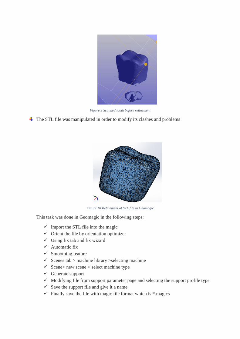
Figure 9 Scanned tooth before refinement
The STL file was manipulated in order to modify its clashes and problems
Figure 10 Refinement of STL file in Geomagic
This task was done in Geomagic in the following steps:
Import the STL file into the magic
Orient the file by orientation optimizer
Using fix tab and fix wizard
Automatic fix
Smoothing feature
Scenes tab > machine library >selecting machine
Scene> new scene > select machine type
Generate support
Modifying file from support parameter page and selecting the support profile type
Save the support file and give it a name
Finally save the file with magic file format which is *.magics
An extensive literature review was performed and best viable dental root implant design
was identified
This task was done by reviewing more than 15 scientific papers from well-respected
journals like: Journal of the Mechanical Behaviour of Biomedical Materials, Journal of
Materials Design and Applications, Implant dentistry and Journal of Dental Sciences. In
this process the optimum design parameters were extracted, and justified. The major
challenge in this process was the medical nature of the task.
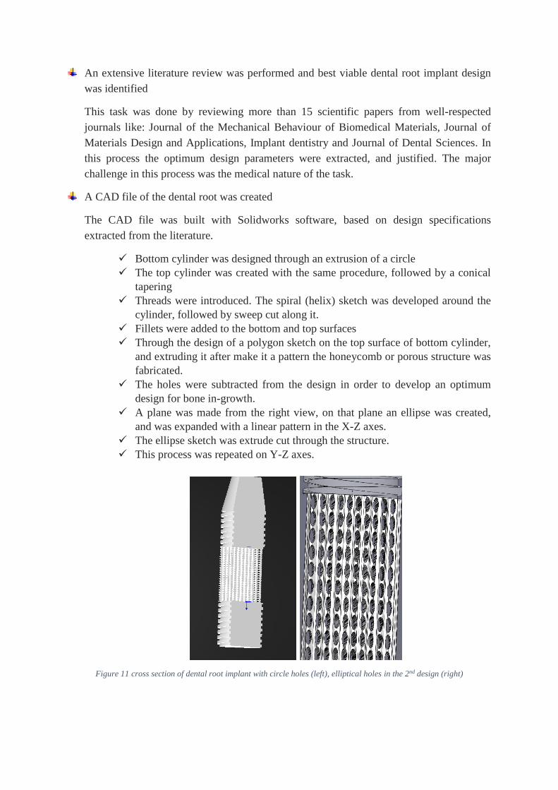
A CAD file of the dental root was created
The CAD file was built with Solidworks software, based on design specifications
extracted from the literature.
Bottom cylinder was designed through an extrusion of a circle
The top cylinder was created with the same procedure, followed by a conical
tapering
Threads were introduced. The spiral (helix) sketch was developed around the
cylinder, followed by sweep cut along it.
Fillets were added to the bottom and top surfaces
Through the design of a polygon sketch on the top surface of bottom cylinder,
and extruding it after make it a pattern the honeycomb or porous structure was
fabricated.
The holes were subtracted from the design in order to develop an optimum
design for bone in-growth.
A plane was made from the right view, on that plane an ellipse was created,
and was expanded with a linear pattern in the X-Z axes.
The ellipse sketch was extrude cut through the structure.
This process was repeated on Y-Z axes.
Figure 11 cross section of dental root implant with circle holes (left), elliptical holes in the 2nd design (right)
Even though additive manufacturing has the capability to produce far more complex
geometries in comparison with traditional manufacturing, the possibility of
manufacturability still depends on specific design guidelines. These guidelines relate
to heat transfer, inclination angle, minimum size or thickness and more, which usually
result in the cost and time consuming process of use of support materials [16, 17]
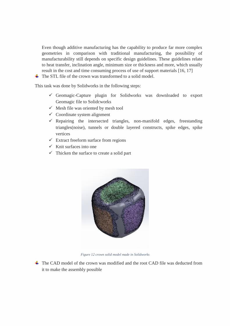
The STL file of the crown was transformed to a solid model.
This task was done by Solidworks in the following steps:
Geomagic-Capture plugin for Solidworks was downloaded to export
Geomagic file to Solidcworks
Mesh file was oriented by mesh tool
Coordinate system alignment
Repairing the intersected triangles, non-manifold edges, freestanding
triangles(noise), tunnels or double layered constructs, spike edges, spike
vertices
Extract freeform surface from regions
Knit surfaces into one
Thicken the surface to create a solid part
Figure 12 crown solid model made in Solidworks
The CAD model of the crown was modified and the root CAD file was deducted from
it to make the assembly possible

Figure 13 CAD model of crown, ready for assembly
Two solid models were assembled together
Figure 14Crown and root implant assembly (circle holes)
Two STL files were created for crown and root implant
The STL file could be directly exported from solidworks.
The last step, parts fabrication
4. Discussion
The optimum design parameters will vary, taking the characteristics and dimensions of the
patient’s jaw into account and may depend on the position of the root in mandibular or
maxillary bone sectors. Available room, damaged bone, proximity of another implant are all
factors that have to be considered before choosing the right implant. Each study showed that
creating as large as possible contact surface between bone and implant, has led to greater
success.
Even though many factors may affect the overall success rate and optimum design of the
implant, one thing is certain: trabecular metal structures have the potential to change the
future for bone implants, not only in dentistry. These structures aid the osseointegration that
has been found integral to successful implantations. Further development of additive
manufacturing techniques and the availability of specialized commercial 3D printing
machines, play vital roles in its future success, as 3D printing works well to create porous
structures; however, the optimum porous structure is not understood yet. Fast manufacturing
of customized dental root implant in a short amount of time may be a possible and affordable
option in a few years, through maturing additive manufacturing and 3D scanning
technologies. Specialized optimisation software for calculating the best possible root implant
design is still the missing piece of the puzzle.
5. Conclusion
An assembly of dental crown and dental root implant was fabricated by the use of 3D
scanning, computer aided design and additive manufacturing. The optimum design was made
in order to achieve the best root shape, bone in-growth and mechanical properties. This was a
cylindrical, threaded implant with as long a length and as wide a diameter as practicable, with
square threads. This was justified by previous studies on stress-based performance and
stability of implants. The potential of trabecular metal structure to revolutionise bone implant
was discussed and the role of modern additive manufacturing technologies and the ideal
candidates were introduced.
References
1. Parr, G.R., Tissue-integrated prostheses: Osseointegration in clinical dentistry: Per-Ingvar Branemark, MD, Ph. D., George A. Zarb, DSS, MS, FRCD (C), and Thomas Albrektsson, MD, Ph. D. Chicago, 1985, Quintessence Publishing Company, Inc. 350 pages, illustrated, indexed. Price $88.00. 1985, Mosby.
2. Kruth, J., et al., Digital manufacturing of biocompatible metal frameworks for complex dental prostheses by means of SLS/SLM. Virtual Prototyping and Rapid Manufacturing-Advanced research in virtual and Rapid Prototyping, Taylor & Francis, London, 2005: p. 139-146.
3. Brånemark, P.-I., et al., Intra-osseous anchorage of dental prostheses: I. experimental studies. Scandinavian Journal of Plastic and Reconstructive Surgery and Hand Surgery, 1969. 3(2): p. 81-100.

4. Baggi, L., et al., Stress-based performance evaluation of osseointegrated dental implants by finite-element simulation. Simulation Modelling Practice and Theory, 2008. 16(8): p. 971-987.
5. Çelen, S. and H. Özden, Laser-induced novel patterns: As smart strain actuators for new-age dental implant surfaces. Applied Surface Science, 2012. 263(0): p. 579-585.
6. Staiger, M.P., et al., Magnesium and its alloys as orthopedic biomaterials: A review. Biomaterials, 2006. 27(9): p. 1728-1734.
7. Savalani, M.M., C.C. Ng, and H.C. Man. Selective Laser Melting of Magnesium for Future Applications in Medicine. in Manufacturing Automation (ICMA), 2010 International Conference on. 2010.
8. Tolochko, N., et al., Dental root implants produced by the combined selective laser sintering/melting of titanium powders. Proceedings of the Institution of Mechanical Engineers, Part L: Journal of Materials Design and Applications, 2002. 216(4): p. 267-270.
9. Elias, C.N., et al., Influence of implant shape, surface morphology, surgical technique and bone quality on the primary stability of dental implants. Journal of the Mechanical Behavior of Biomedical Materials, 2012. 16(0): p. 169-180.
10. Steigenga, J.T., et al., Dental implant design and its relationship to long-term implant success. Implant dentistry, 2003. 12(4): p. 306-317.
11. Lee, C.-C., et al., Effects of implant threads on the contact area and stress distribution of marginal bone. Journal of Dental Sciences, 2010. 5(3): p. 156-165.
12. Lee, W.H. and C.Y. Hyun, XPS study of porous dental implants fabricated by electro-discharge-sintering of spherical Ti–6Al–4V powders in a vacuum atmosphere. Applied Surface Science, 2006. 252(12): p. 4250-4256.
13. zimmer, http://www.zimmerdental.com/tm. 14. Hsu, H.-C., et al., Processing and mechanical properties of porous Ti–7.5Mo alloy. Materials &
Design, 2013. 47(0): p. 21-26. 15. Chen, J., et al., Design and manufacture of customized dental implants by using reverse
engineering and selective laser melting technology. The Journal of Prosthetic Dentistry, (0). 16. Leary, M., et al., Optimal topology for additive manufacture: A method for enabling additive
manufacture of support-free optimal structures. Materials & Design, 2014. 63(0): p. 678-690.
17. Strano, G., et al., A new approach to the design and optimisation of support structures in additive manufacturing. The International Journal of Advanced Manufacturing Technology, 2013. 66(9-12): p. 1247-1254.