AMSN09 SEISMIC SURVEY OL 4 & EP 115 NORTHERN …
92
AMSN09 SEISMIC SURVEY OL 4 & EP 115 NORTHERN TERRITORY ACQUISITION REPORT Compiled by: A. White Santos Ltd. November 2011
Transcript of AMSN09 SEISMIC SURVEY OL 4 & EP 115 NORTHERN …
AMSN09 SEISMIC SURVEY
OL 4 & EP 115
NORTHERN TERRITORY
ACQUISITION REPORT
Compiled by: A. White Santos Ltd.
November 2011
TABLE OF CONTENTS
1 INTRODUCTION ................................................................................................................................... 3
1.1 GENERAL ................................................................................................................................................ 3
1.2 TIMETABLE OF MAIN EVENTS ........................................................................................................ 3
2 SURVEY SCOPE AND OBJECTIVES ................................................................................................. 5
3 DATA ACQUISITION ............................................................................................................................ 6
3.1 PERMITTING ......................................................................................................................................... 6
3.1.1 GENERAL ......................................................................................................................................... 6
3.2 LOGISTICS AND COMMUNICATIONS ............................................................................................ 6
3.3 SURVEYING ........................................................................................................................................... 6
3.4 CULTURAL HERITAGE CLEARANCE ............................................................................................ 6
3.5 LINE PREPARATION ........................................................................................................................... 7
3.5.1 EQUIPMENT .................................................................................................................................... 7 3.5.2 OPERATIONS ................................................................................................................................... 7
3.6 DRILLING ............................................................................................................................................... 8
3.6.1 EQUIPMENT .................................................................................................................................... 8 3.6.2 OPERATIONS ................................................................................................................................... 8
3.7 RECORDING .......................................................................................................................................... 9
3.7.1 EQUIPMENT .................................................................................................................................... 9 3.7.2 RECORDING PARAMETERS ........................................................................................................ 10 3.7.3 OPERATIONS ................................................................................................................................. 10
3.8 WEATHERING SURVEY .................................................................................................................... 11
3.8.1 GENERAL ....................................................................................................................................... 11
3.9 ENVIRONMENT ................................................................................................................................... 12
3.9.1 GENERAL ....................................................................................................................................... 12 3.9.2 OPERATIONAL OBSERVATIONS ................................................................................................. 12 3.9.3 RESTORATION ............................................................................................................................... 12
APPENDIX 1 – DSS POSITIONING FINAL OPERATIONS REPORT(S) ................................................ 13
APPENDIX 2 – TERREX SEISMIC FINAL OPERATIONS REPORT ...................................................... 14
APPENDIX 3 - RECORDING PRODUCTION STATISTICS ...................................................................... 15
APPENDIX 4 - PERSONNEL LIST ................................................................................................................. 17
APPENDIX 5 – DRILLING PRODUCTION .................................................................................................. 19
APPENDIX 6 - TAPE LIST ............................................................................................................................... 22
APPENDIX 7 - MAPS ........................................................................................................................................ 24
1 INTRODUCTION
1.1 GENERAL
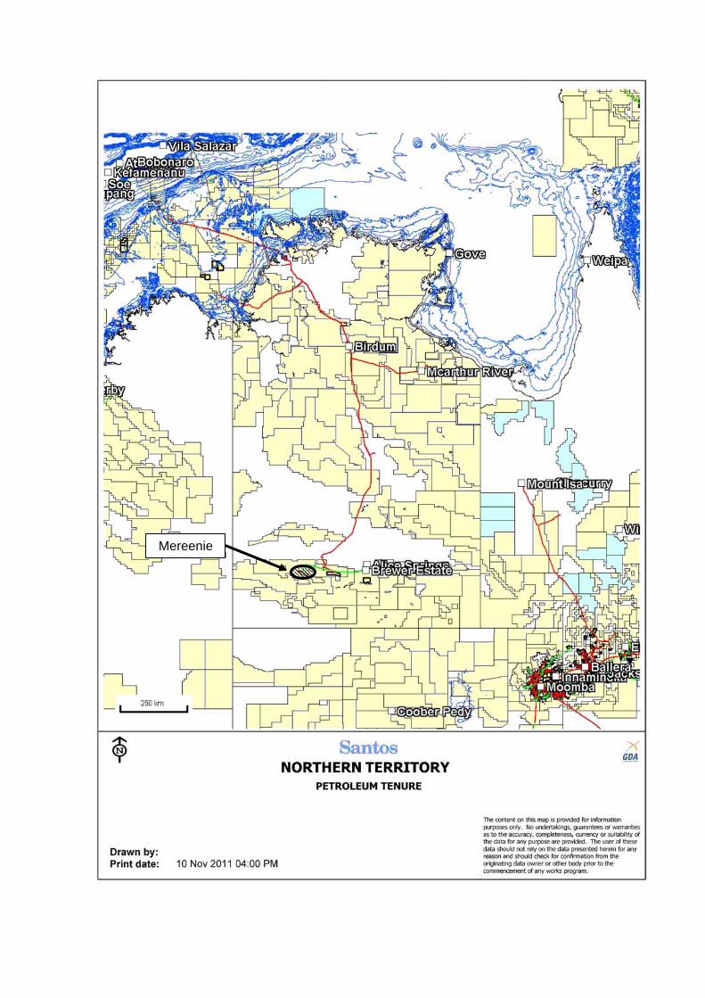
In the year 2011 Santos Ltd., as operator of OL 4 carried out approximately 8.5 linear kilometres of 2D seismic imaging in the Mereenie field area as the AMSN09 Mereenie 2D Seismic Survey.
The following table details the companies involved in the acquisition of the survey.
Activity Contractor
Line Preparation Terrex Contracting Pty. Ltd Surveying Dynamic Satellite Surveys Pty Ltd Seismic Recording Terrex Seismic (Crew 402) Shothole Drilling Gorey Cole Drillers Pty Ltd Shothole loading Nedrill Blasting Contractors Pty Ltd
Santos Ltd contracted Anthony Kenny and John Allen to supervise the various phases
of the field operations. Sections below, describing field operations, are largely drawn from their observations.
It should be noted that the survey was originally scheduled for recording in October
2009, however the required shot hole drill rig was unavailable so operations had to be delayed after line preparation and surveying was completed. It was some 21 months later before Santos managed to coordinate a seismic crew passing by and an available drill rig to complete the survey.
Processing of the seismic data was carried out in house by Santos, and will be the
subject of a separate report. This report describes the data acquisition of AMSN09 Mereenie 2D Seismic Survey,
located around the West Mereenie #15 well, located in the Mereenie Field approximately 280km west of Alice Springs in the Northern Territory.
1.2 TIMETABLE OF MAIN EVENTS
Date Activity 20/08/2009 Notice of Intention sent to DPIFM 11/09/2009 Sacred Site Clearance certificate issued. 25/09/2009 Line preparation commenced & completed. 25/09/2009 Survey commenced. 25/09/2009 Survey completed.
5/05/2011 Line preparation (re-open line) commenced &
completed. 5/05/2011 Re-pegging of line commenced. 6/05/2011 Re-pegging of line completed. 6/05/2011 Shot hole drilling commenced. 8/05/2011 Shot hole drilling completed.
17/05/2011 Seismic recording commenced. 19/05/2011 Seismic recording completed.
Mereenie
2 SURVEY SCOPE AND OBJECTIVES
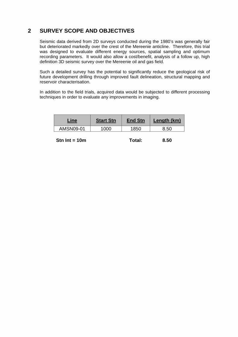
Seismic data derived from 2D surveys conducted during the 1980’s was generally fair but deteriorated markedly over the crest of the Mereenie anticline. Therefore, this trial was designed to evaluate different energy sources, spatial sampling and optimum recording parameters. It would also allow a cost/benefit, analysis of a follow up, high definition 3D seismic survey over the Mereenie oil and gas field.
Such a detailed survey has the potential to significantly reduce the geological risk of
future development drilling through improved fault delineation, structural mapping and reservoir characterisation.
In addition to the field trials, acquired data would be subjected to different processing
techniques in order to evaluate any improvements in imaging.
Line Start Stn End Stn Length (km)
AMSN09-01 1000 1850 8.50
Stn Int = 10m
Total: 8.50
3 DATA ACQUISITION 3.1 PERMITTING
3.1.1 GENERAL
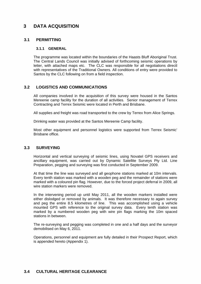
The programme was located within the boundaries of the Haasts Bluff Aboriginal Trust. The Central Lands Council was initially advised of forthcoming seismic operations by letter, with attached maps etc. The CLC was responsible for all negotiations directl with representatives of the Traditional Owners. All conditions of entry were provided to Santos by the CLC following on from a field inspection.
3.2 LOGISTICS AND COMMUNICATIONS All companies involved in the acquisition of this survey were housed in the Santos
Mereenie camp facility for the duration of all activities. Senior management of Terrex Contracting and Terrex Seismic were located in Perth and Brisbane.
All supplies and freight was road transported to the crew by Terrex from Alice Springs. Drinking water was provided at the Santos Mereenie Camp facility. Most other equipment and personnel logistics were supported from Terrex Seismic’
Brisbane office. 3.3 SURVEYING Horizontal and vertical surveying of seismic lines, using Novatel GPS receivers and
ancillary equipment, was carried out by Dynamic Satellite Surveys Pty Ltd. Line Preparation, pegging and surveying was first conducted in September 2009.
At that time the line was surveyed and all geophone stations marked at 10m intervals. Every tenth station was marked with a wooden peg and the remainder of stations were marked with a coloured pin flag. However, due to the forced project deferral in 2009, all wire station markers were removed. In the intervening period up until May 2011, all the wooden markers installed were either dislodged or removed by animals. It was therefore necessary to again survey and peg the entire 8.5 kilometres of line. This was accomplished using a vehicle mounted GPS with reference to the original survey data. Every tenth station was marked by a numbered wooden peg with wire pin flags marking the 10m spaced stations in between.
The re-surveying and pegging was completed in one and a half days and the surveyor demobilised on May 6, 2011.
Operations, personnel and equipment are fully detailed in their Prospect Report, which
is appended hereto (Appendix 1). 3.4 CULTURAL HERITAGE CLEARANCE
The Mereenie 2D project falls within an area administered by the Haasts Bluff Aboriginal Land Trust. Santos engaged the services of Traditional owners, via existing agreements between the Traditional Owners, the Central Lands Council and Santos, to perform a pre clearance (ie: scout ahead of any line preparation activities commencing) to locate, mark and provide detours to direct subsequent line preparation activities around any cultural heritage sites found.
Santos were not party to this inspection, nor any site details located, however we were issued a Sacred Site Clearance Certificate granting us access t the area with a number of specific restrictions, including approval to operate in a specified corridor.
3.5 LINE PREPARATION
3.5.1 EQUIPMENT Line preparation was carried out by Terrex Contracting who supplied a total of two
personnel. Terrex contracting supplied the following equipment:
1 x Komatsu D65EX bulldozer 1 x Kenworth prime mover
1 x Toyota 4x4 utility 1 x Low loader
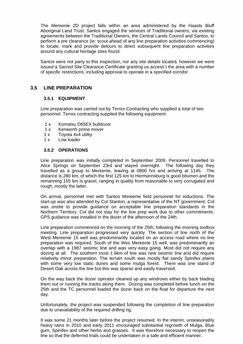
3.5.2 OPERATIONS Line preparation was initially completed in September 2009. Personnel travelled to Alice Springs on September 23rd and stayed overnight. The following day they travelled as a group to Mereenie, leaving at 0800 hrs and arriving at 1145. The distance is 280 km, of which the first 125 km to Hermannsburg is good bitumen and the remanning 155 km is gravel, ranging in quality from reasonable to very corrugated and rough, mostly the latter. On arrival, personnel met with Santos Mereenie field personnel for inductions. The start-up was also attended by Col Stanton, a representative of the NT government. Col was onsite to provide guidance on acceptable line preparation standards in the Northern Territory. Col did not stay for the line prep work due to other commitments. GPS guidance was installed in the dozer of the afternoon of the 24th. Line preparation commenced on the morning of the 25th, following the morning toolbox meeting. Line preparation progressed very quickly. The section of line north of the West Mereenie 15 well was predominantly located on an access road where no line preparation was required. South of the Wes Mereenie 15 well, was predominantly an overlap with a 1987 seismic line and was very easy going. Most did not require any dozing at all. The southern most 1.6km of line was new seismic line and did require relatively minor preparation. The terrain south was mostly flat sandy Spinifex plains with some very low static dunes and some mulga forest. There was one stand of Desert Oak across the line but this was sparse and easily traversed. On the way back the dozer operator cleaned up any windrows either by back blading them out or running the tracks along them. Dozing was completed before lunch on the 25th and the TC personnel loaded the dozer back on the float for departure the next day. Unfortunately, the project was suspended following the completion of line preparation due to unavailability of the required drilling rig. It was some 21 months later before the project resumed. In the interim, unseasonably heavy rains in 2010 and early 2011 encouraged substantial regrowth of Mulga, Blue gum, Spinifex and other herbs and grasses. It was therefore necessary to reopen the line so that the deferred trials could be undertaken in a safe and efficient manner.
Terrex Contracting had earthmoving equipment stacked in Alice Springs and were able to mobilise a bulldozer and appropriate personnel to Mereenie on May 4, 2011. A surveyor also accompanied this group to re-peg the line. Preparation work was once again straight forward and only minimal blade work was required. If anything, vegetation levels in 2011 were higher than that originally found in 2009, due to the extensive rains the area experienced in the interim period. There was no deviation from the earlier line apart from a new 20m section prepared at right angles to the original at station 1575.5. This was done to enable the drilling of four, six metre deep holes required for dynamite charge size comparison tests. Work was completed on May 5. Personnel and equipment demobilised to Alice Springs the following day.
3.6 DRILLING
Alice Springs based drilling contractor, Gory & Cole Drillers Pty Ltd were contracted to drill, case and cap eighty four (84) Kelly depth holes into which explosive charges were to be loaded and detonated, the seismic responses then processed and compared with those obtained over the same station range by the surface vibroseis method.
3.6.1 EQUIPMENT
1 x Ingersoll Rand TH60 hydraulically driven top-head drive drilling rig with IR
750cfm/250psi compressor and drill stem carousel. Rig mounted on 6x4 Paystar with dual rear wheels and 3 hydraulic levelling jacks.
10 x 6m lengths 4.5” drill stems 2 x 6” Button hammer bits 2 x 6” Chevron blade bits 85 x 6m lengths of 90mm diameter PVC storm water pipes with end caps (supplied
by Santos Ltd) 1 x Acco twin steer, 8 wheel water truck fitted with 2,000lt diesel and 5,000lt water
tanks. 6.5m flat deck for drill stem 1 x Toyota 4x4 utility
3.6.2 OPERATIONS
Drilling personnel and equipment mobilised to Mereenie on May 5 and on arrival the driller and both offsiders completed the mandatory Santos inductions. Eighty holes were to be drilled (stations 1580 to 1659) for the dynamite trial. These were to be 6 metres deep and spaced 10 metres apart, cased with 90mm PVC stormwater pipe and capped. Four additional holes were to be drilled normal to the trial line for a charge size test. The four test holes were drilled first, east of station 1575.5 and spaced 5 metres apart. The easternmost three were air drilled to 6 metres through dry consolidated sand using a 6” Chevron blade bit. The fourth intersected hard sandstone at 4 metres, the last 2 metres being hammer drilled. Thereafter, all holes were drilled using a down-hole hammer and 6” button bit. All production shot holes were drilled to 6 metres except for the northernmost five holes which were drilled to 5.25 metres due to short lengths of casing. All holes intersected hard to very hard buff/white sandstone at depths varying from 4 metres at the southern end of line to less than 0.5 metre at the northern end. Loose unconsolidated sands were generally present for the first 0.25 metres followed by consolidated clay rich sand to the top of the sandstone. On completion of drilling on May 8 the contractor demobilised to Alice Springs the following day.
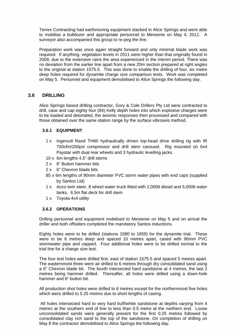
Drilling production is summarised in the table below.
Date # Holes Drilled 6/05/2011 30 7/05/2011 33 8/05/2011 21
As each hole was cased, drill cuttings and sand was used to fill the void between the casing and hole wall. Overall, drilling operations utilising a top head drive rig are inherently slower than that of its rotary table counterpart due almost entirely to the slower acting hydraulic systems. Raising and lowering of drill stem is slower as is the adding or removal of stem which is stacked in a vertical carousel. Move up time between closely spaced holes is also slow as the longer mast has to be lowered then raised because of its overall weight including the hydraulically operated drive head. Drilling statistics for May 8 are shown below. This day was chosen as up to 5 metres of hard sandstone was encountered in drill holes.
Total charge hours: 8:12 Total non charge hours: 0:54 Total drill time: 7:18 Total holes drilled: 21 Total metres drilled: 122.25 Average time/hole: 21 minutes Average time /metre: 3.6minutes
A more detailed drilling analysis can be found in Appendix 5. It should be noted that this only covers the last two days of drilling production. No records were submitted to Santos for May 6th.
3.7 RECORDING
3.7.1 EQUIPMENT
Terrex Seismic supplied and operated a complete seismic data acquisition system, including, as required. Recording Equipment
1 x Sercel 428A, 24 bit telemetry recording system complete with line interface and 2000 channel acquisition and processing module
1 x Sun Microsystems Sun Blade 2500 server 1 x Dell Optiplex GX620 processor with Windows XP 32 operating system 2 x NAS 320Gb hard drives plus 2 spares 1 x ULTRIUM dual LT02 tape drive 1 x Pelton VibPro encode sweep generator. 4 x Pelton VibPro VCE’s 1 x Pelton VIBSIG real time QC system 4 x Wall mounted, flat LCD colour display screens 1 x Veritas iSys V12 thermal plotter 1 x Optus mobilsat phone 2 x Motorola 50W VHF radios 1 x Uniden 25W UHF radio 1 x Kodan HF radio
450 x strings Sensor SM4, 10Hz geophones, 12/string 220 x cables with 4 combined takeout/A-D converters per cable Sufficient power units and batteries to match cable numbers
Automotive Equipment
1 x Isuzu 4x4 airconditioned recording truck 4 x I/O AHV-IV articulated, hydrostatic 60,000lb vibrators 1 x Paystar 6 x6 vibrator service truck 1x Toyota 4x4 utility – line boss 1x Toyota 4x4 utilities – troubleshooters 2x Toyota 4x4 utilities – cable trucks 1 x Toyota 4x4 utilities – geophone trucks 2x Toyota 4x4 Landcruiser wagons – line crew 1 x Kenworth prime mover – vibrator spare parts 1 x Paystar 6x6 spread truck 1 x Kenworth prime movers - spread
A complete list of automotive equipment is included in Terrex Seismic Operations Report. A copy of this report is attached as Appendix 2.
3.7.2 RECORDING PARAMETERS
Recording parameters are detailed in the Terrex Seismic Operations Report. A copy of this report is attached as Appendix 2.
3.7.3 OPERATIONS
Terrex Seismic recording crew 402 mobilised on May 15, arriving at the Santos Mereenie camp late afternoon. The three vibrators and vibrator service truck that were trucked to site arrived early morning on the 16th. All crew members attended a site specific induction on May 16 before commencing the task of laying out spread. For the trials which were to follow, spread had to be laid over the entire 8.5 kilometres of line (stations 1050 to 1900). With a receiver spacing of 10 metres, this required 851 sets of geophones with each set comprised of 6 elements arrayed parallel to the line and centred on the half station. In addition, between stations 1398 and 1698m, all 6 elements in every third set had to be buried starting with the group at station 1398, the objective being to assess later the effectiveness or otherwise of random noise cancellation.
Five seismic trials and a detonator test were conducted. These are listed below in the order in which they were completed.
• 6 second, 3-100Hz vibroseis sweep length trial, vp’s 1659 - 1580 • 4 second, 3-100Hz vibroseis sweep length trial, vp’s 1580 – 1659 • ‘Cap under’ tests • 5 dynamite charge size trial • 6 second vibroseis production trial, vp’s 1900 – 1660; 1579 - 1050 • Dynamite source trial, stations 1581 – 1659
Vibroseis sweep length trials, cap tests and the charge size comparison trials were all completed on the first day of recording, May 17. The first ninety two vp’s of the six second sweep production data were also recorded. For the sweep length trials, three vibrators were arrayed in line with a pad-pad spacing of 12.5 metres. The middle vibrator was centred on the station. Two sweeps were executed at each station and data recorded by all 851 live geophone groups. Data from the first sweep were correlated and written to tape, the second sweep correlated
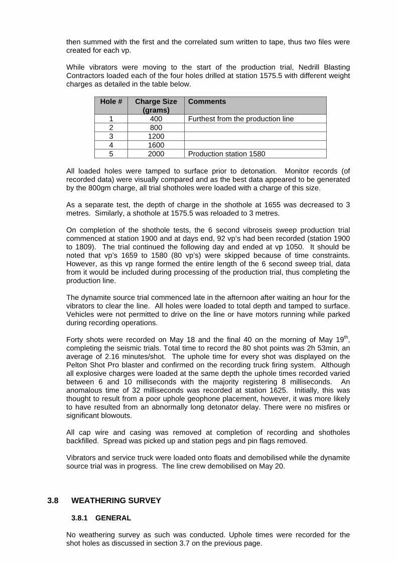
then summed with the first and the correlated sum written to tape, thus two files were created for each vp. While vibrators were moving to the start of the production trial, Nedrill Blasting Contractors loaded each of the four holes drilled at station 1575.5 with different weight charges as detailed in the table below.
Hole # Charge Size (grams)
Comments
1 400 Furthest from the production line 2 800 3 1200 4 1600 5 2000 Production station 1580
All loaded holes were tamped to surface prior to detonation. Monitor records (of recorded data) were visually compared and as the best data appeared to be generated by the 800gm charge, all trial shotholes were loaded with a charge of this size. As a separate test, the depth of charge in the shothole at 1655 was decreased to 3 metres. Similarly, a shothole at 1575.5 was reloaded to 3 metres. On completion of the shothole tests, the 6 second vibroseis sweep production trial commenced at station 1900 and at days end, 92 vp’s had been recorded (station 1900 to 1809). The trial continued the following day and ended at vp 1050. It should be noted that vp’s 1659 to 1580 (80 vp’s) were skipped because of time constraints. However, as this vp range formed the entire length of the 6 second sweep trial, data from it would be included during processing of the production trial, thus completing the production line. The dynamite source trial commenced late in the afternoon after waiting an hour for the vibrators to clear the line. All holes were loaded to total depth and tamped to surface. Vehicles were not permitted to drive on the line or have motors running while parked during recording operations. Forty shots were recorded on May 18 and the final 40 on the morning of May 19th, completing the seismic trials. Total time to record the 80 shot points was 2h 53min, an average of 2.16 minutes/shot. The uphole time for every shot was displayed on the Pelton Shot Pro blaster and confirmed on the recording truck firing system. Although all explosive charges were loaded at the same depth the uphole times recorded varied between 6 and 10 milliseconds with the majority registering 8 milliseconds. An anomalous time of 32 milliseconds was recorded at station 1625. Initially, this was thought to result from a poor uphole geophone placement, however, it was more likely to have resulted from an abnormally long detonator delay. There were no misfires or significant blowouts. All cap wire and casing was removed at completion of recording and shotholes backfilled. Spread was picked up and station pegs and pin flags removed. Vibrators and service truck were loaded onto floats and demobilised while the dynamite source trial was in progress. The line crew demobilised on May 20.
3.8 WEATHERING SURVEY
3.8.1 GENERAL
No weathering survey as such was conducted. Uphole times were recorded for the shot holes as discussed in section 3.7 on the previous page.
3.9 ENVIRONMENT
3.9.1 GENERAL
As operator, Santos Ltd has, for a number of years, been committed to planning and conducting seismic operations in such a way that environmental disturbance is avoided or minimised, and affected areas can rehabilitate naturally in a reasonable time frame. These objectives have most recently been set out and discussed in the publications “Statement of Environmental Objectives: Geophysical Operations” Santos Ltd, June 2006, and “Environmental Impact Report: Geophysical Operations” Santos Ltd, June 2006.
The commitment has normally included the distribution of copies of the above to all contractors’ personnel, and continual pressure by Santos Ltd field representatives on these personnel to conform to the principles and requirements of these documents. Compliance with the Aboriginal Heritage Act has also been stressed and, during the year, the strategy to ensure meticulous adherence to standard Santos procedures relating to Cultural Heritage Management and Environmental Sensitivity was reinforced by special training of key personnel, and daily meetings to re-iterate key issues and procedures.
3.9.2 OPERATIONAL OBSERVATIONS This trial was conducted within the producing Mereenie oil and gas field, approximately 280 kilometres west of Alice Springs, in the ‘Western Desert’ region. Terrain is a mix of relatively flat to gently undulating spinifex sand plains and randomly spaced low, rounded, east-northeast orientated sand dunes and intervening swales. These landforms occupy the southern two thirds of the trial line area and support open Mulga and lesser Blue Gum woodlands. Single and small colonies of Desert Oak are fairly common on the sand dunes and associated swales. A pronounced one and a half kilometre wide, east-west trending sandstone ridge is present in the vicinity of the Mereenie West 15 well. Light grey alluvial flats occur at the northern and southern extremities of the line. Both landforms support dense Mulga woodlands. Weather during both stages of this trial was generally fine and mild but mornings and evenings were cold. Prevailing south to southeast winds during Stage I were moderate which helped disperse the fine siliceous dust created during drilling operations. Winds during Stage II were mostly light. There was no rain recorded.
3.9.3 RESTORATION
It should be noted that a portion of this line was recorded over an existing track. In this area, no restoration will be required. The reminder of the line was predominantly a re-shoot of a 1987 seismic line. At the time of completion of recording, it was decided that no immediate restoration was required. At the time of writing this report, nearly 6 months after recoding was completed, indications are that the line is starting to revegetate naturally, despite the lack of follow up rains. Santos will monitor the line over the next few months, particularly after any rains, to ensure that erosion of the prepared line does not become an issue. There is no current evidence of erosion.
APPENDIX 1 – DSS POSITIONING FINAL OPERATIONS REPORT(S)
11042
Final Operations Report
on the
2011 Survey Reinstatement
of the
2009 Mereenie Trial 2D Seismic Surveyfor
Terrex Seismic Pty Ltdand
SANTOS Limited
May 2011
Terrex Seismic Pty Ltd / SANTOS Limited 2011 Mereenie 2D Reinstatement
© Dynamic Satellite Surveys Pty Ltd 2011
This work is copyright. No part may be reproduced by any process without prior written permission
from Dynamic Satellite Surveys Pty Ltd. Requests and inquiries concerning reproduction and rights
should be addressed to:
The Director
Dynamic Satellite Surveys Pty Ltd
PO Box 713
Yeppoon QLD 4703
Telephone: 07 4939 2866
International: +61 7 4939 2866
Facsimile: 07 4939 2867
E-mail: [email protected]
Dynamic Satellite Surveys Pty Ltd has a Quality Management System,
externally certified to AS/NZS ISO 9001:2008 standards by
SAI Global Pty Ltd (Lic# QEC10046).
This project was undertaken for Terrex Seismic Pty Ltd and SANTOS Limited.
The sole purpose of the job was to reinstate a 2D Seismic Line which was originally surveyed in
2009. The use of the data for any other purpose is not authorised.
All data contained in this report and on the attached CD is deemed to be final and overrides any
previous data received from DSS, unless otherwise stated.
Job #11042 - May 2011 - Report Version 0 © Dynamic Satellite Surveys Pty Ltd 2011
Table of Contents
OPERATIONS SUMMARY . . . . . . . . . . . . . . . . . . . . . . . . . . . . . . . . . . . . . . . . . . . . . . . . . . . . 1
APPENDICES . . . . . . . . . . . . . . . . . . . . . . . . . . . . . . . . . . . . . . . . . . . . . . . . . . . . . . . . . . . . . . 2
2009 Mereenie Trial 2D Seismic Survey Report . . . . . . . . . . . . . . . . . . . . . . . . . . . . . . . A - 1
Job #11042 - May 2011 - Report Version 0 © Dynamic Satellite Surveys Pty Ltd 2011
Terrex Seismic Pty Ltd / SANTOS Limited 2011 Mereenie 2D Reinstatement
1
OPERATIONS SUMMARY
The following report covers the Reinstatement of the 2009 Mereenie Trial 2D Seismic Survey,
performed by Dynamic Satellite Surveys Pty Ltd (DSS) whilst contracted to Terrex Seismic Pty
Ltd (Terrex) for SANTOS Limited (SANTOS).
The Mereenie prospect consisted of one (1) line, AMSN09_01. This line was a total of 8.5
kilometres and was pegged with a station interval of ten metres (10m).
The line was situated within the Mereenie oil field area, located approximately 300 kilometres West
of Alice Springs.
The reinstatement operations were completed between the 3rd and 6th of May 2011. Dirk Smit
(surveyor) travelled to Alice Springs to meet with Terrex Contracting on the 3rd of May. Dirk and
Terrex Contracting mobilised to Mereenie and completed site inductions on the 4th of May.
Dirk supervised the line preparation prior to commencing pegging on AMSN09_01 on the 5th of May.
As all pegs remaining were in poor condition, it was necessary to re-peg the entire line. On the 6th
of May pegging and control operations were completed and Dirk demobilised to Alice Springs.
No further services, other than the line pointing and reinstatement of Line AMSN09_01, were
provided.
DSS reinstated the original stations using the control installed during the original survey. Checks
were made to ensure the integrity of the original network. Consequently, all original operational
aspects were reflected in the 2009 Mereenie Trial 2D Seismic Survey report, attached to this
document as Appendix A.
Job #11042 - May 2011 - Report Version 0 © Dynamic Satellite Surveys Pty Ltd 2011
1
Terrex Seismic Pty Ltd / SANTOS Limited 2011 Mereenie 2D Reinstatement
2
APPENDICES
Job #11042 - May 2011 - Report Version 0 © Dynamic Satellite Surveys Pty Ltd 2011
2
Terrex Seismic Pty Ltd / SANTOS Limited 2011 Mereenie 2D Reinstatement
2009 Mereenie Trial 2D Seismic Survey Report
Job #11042 - May 2011 - Report Version 0 © Dynamic Satellite Surveys Pty Ltd 2011
A - 1
09066
Final Operations Report
on the
2009 Mereenie Trial 2D Seismic Surveyfor
Terrex Seismic Pty Ltd and
SANTOS Limited
September 2009

Terrex Seismic Pty Ltd / SANTOS Limited 2009 Mereenie 2D Seismic Survey
© Dynamic Satellite Surveys Pty Ltd 2009
This work is copyright. No part may be reproduced by any process without prior written
permission from Dynamic Satellite Surveys Pty Ltd. Requests and inquiries concerning
reproduction and rights should be addressed to:
The Director
Dynamic Satellite Surveys Pty Ltd
PO Box 713
Yeppoon QLD 4703
Telephone: 07 4939 2866
International: +61 7 4939 2866
Facsimile: 07 4939 2867
E-mail: [email protected]
Dynamic Satellite Surveys Pty Ltd has a Quality Management System,
externally certified to AS/NZS ISO 9001:2008 standards by
SAI Global Pty Ltd (Lic# QEC10046).
This project was undertaken for Terrex Seismic Pty Ltd and SANTOS Limited.
The sole purpose of the job was to install and survey 2D Seismic Lines. The use of
the data for any other purpose is not authorised.
All data contained in this report and on the attached CD is deemed to be final and
overrides any previous data received from DSS, unless otherwise stated.
Job #09066 - September 2000 - Report Version 0 © Dynamic Satellite Surveys Pty Ltd 2009
Table of Contents
INTRODUCTION . . . . . . . . . . . . . . . . . . . . . . . . . . . . . . . . . . . . . . . . . . . . . . . . . . . 1
INSTRUMENTATION AND PERSONNEL . . . . . . . . . . . . . . . . . . . . . . . . . . . . . . . . 2
2.1 Personnel and Logistics . . . . . . . . . . . . . . . . . . . . . . . . . . . . . . . . . . . 2
2.2 Equipment . . . . . . . . . . . . . . . . . . . . . . . . . . . . . . . . . . . . . . . . . . . . . 3
SURVEY REFERENCE SYSTEMS . . . . . . . . . . . . . . . . . . . . . . . . . . . . . . . . . . . . . . 4
3.1 Geodetic Datum . . . . . . . . . . . . . . . . . . . . . . . . . . . . . . . . . . . . . . . 4
3.2 Map Projection . . . . . . . . . . . . . . . . . . . . . . . . . . . . . . . . . . . . . . . . . . 5
3.3 Height Datum . . . . . . . . . . . . . . . . . . . . . . . . . . . . . . . . . . . . . . . . . . . 5
SURVEY CONTROL . . . . . . . . . . . . . . . . . . . . . . . . . . . . . . . . . . . . . . . . . . . . . . . . . 7
MONUMENTATION . . . . . . . . . . . . . . . . . . . . . . . . . . . . . . . . . . . . . . . . . . . . . . . . . 8
METHOD OF SURVEY . . . . . . . . . . . . . . . . . . . . . . . . . . . . . . . . . . . . . . . . . . . . . . . 9
6.1 Line Preparation . . . . . . . . . . . . . . . . . . . . . . . . . . . . . . . . . . . . . . . . . 9
6.2 GPS Surveying . . . . . . . . . . . . . . . . . . . . . . . . . . . . . . . . . . . 10
6.3 Processing and Quality Control . . . . . . . . . . . . . . . . . . . . . . . . . . . . 11
DATA PRESENTATION . . . . . . . . . . . . . . . . . . . . . . . . . . . . . . . . . . . . . . . . . . . . . 12
SAFETY . . . . . . . . . . . . . . . . . . . . . . . . . . . . . . . . . . . . . . . . . . . . . . . . . . . . . . . . . 13
OPERATIONAL ASPECTS . . . . . . . . . . . . . . . . . . . . . . . . . . . . . . . . . . . . . . . . . . . 14
CONCLUSIONS AND RECOMMENDATIONS . . . . . . . . . . . . . . . . . . . . . . . . . . . . 15
APPENDICES . . . . . . . . . . . . . . . . . . . . . . . . . . . . . . . . . . . . . . . . . . . . . . . . . . . . . 16
Survey Control . . . . . . . . . . . . . . . . . . . . . . . . . . . . . . . . . . . . . . . . . . . . . . . A - 1
Project Map . . . . . . . . . . . . . . . . . . . . . . . . . . . . . . . . . . . . . . . . . . . . . . . . . . B - 1
Line Length Summary . . . . . . . . . . . . . . . . . . . . . . . . . . . . . . . . . . . . . . . . . . C - 1
Environmental Monitoring Points (EMPs) . . . . . . . . . . . . . . . . . . . . . . . . . . . D - 1
Photographs . . . . . . . . . . . . . . . . . . . . . . . . . . . . . . . . . . . . . . . . . . . . . . . . . E - 1
Trace Diagrams . . . . . . . . . . . . . . . . . . . . . . . . . . . . . . . . . . . . . . . . . . . . . . . F - 1
Job #09066 - September 2000 - Report Version 0 © Dynamic Satellite Surveys Pty Ltd 2009
Terrex Seismic Pty Ltd / SANTOS Limited 2009 Mereenie 2D Seismic Survey
1
INTRODUCTION
The following report covers the 2009 Mereenie Trial 2D Seismic Survey, performed by
Dynamic Satellite Surveys Pty Ltd (DSS) whilst contracted to Terrex Seismic Pty Ltd
(Terrex) for SANTOS Limited (SANTOS).
The Mereenie prospect consisted of one (1) line, AMSN09_01, with a total of 8.5
kilometres, pegged with a station interval of ten metres (10m).
The line was situated within the Mereenie Oil field area, which is some 300 kilometres
West of Alice Springs.
The survey operations were completed between the 25th and 26th of September 2009.
Job #09066 - September 2000 - Report Version 0 © Dynamic Satellite Surveys Pty Ltd 2009
1
Terrex Seismic Pty Ltd / SANTOS Limited 2009 Mereenie 2D Seismic Survey
2
INSTRUMENTATION AND PERSONNEL
2.1 Personnel and Logistics
DSS personnel involved in the survey were as follows.
Steve Wardle - Bachelor of Surveying (Otago)
- Senior Surveyor
- 1 year seismic experience
Personnel and equipment logistics were supported by the DSS Yeppoon office. Steve
was accommodated at the Mereenie Camp.
Job #09066 - September 2000 - Report Version 0 © Dynamic Satellite Surveys Pty Ltd 2009
2
Terrex Seismic Pty Ltd / SANTOS Limited 2009 Mereenie 2D Seismic Survey
2.2 Equipment
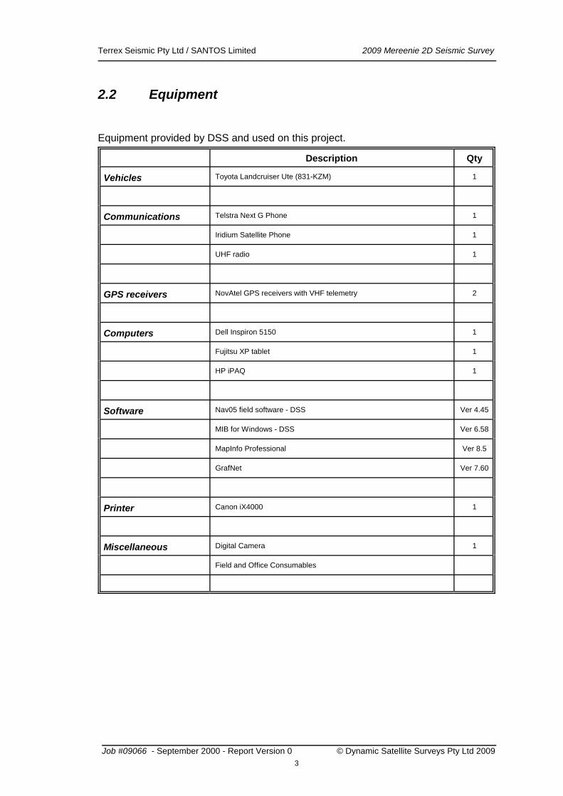
Equipment provided by DSS and used on this project.
Description Qty
Vehicles Toyota Landcruiser Ute (831-KZM) 1
Communications Telstra Next G Phone 1
Iridium Satellite Phone 1
UHF radio 1
GPS receivers NovAtel GPS receivers with VHF telemetry 2
Computers Dell Inspiron 5150 1
Fujitsu XP tablet 1
HP iPAQ 1
Software Nav05 field software - DSS Ver 4.45
MIB for Windows - DSS Ver 6.58
MapInfo Professional Ver 8.5
GrafNet Ver 7.60
Printer Canon iX4000 1
Miscellaneous Digital Camera 1
Field and Office Consumables
Job #09066 - September 2000 - Report Version 0 © Dynamic Satellite Surveys Pty Ltd 2009
3
Terrex Seismic Pty Ltd / SANTOS Limited 2009 Mereenie 2D Seismic Survey
3
SURVEY REFERENCE SYSTEMS
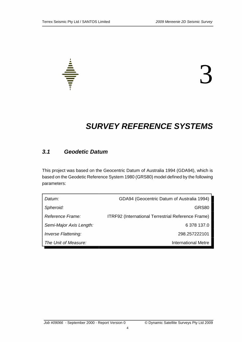
3.1 Geodetic Datum
This project was based on the Geocentric Datum of Australia 1994 (GDA94), which is
based on the Geodetic Reference System 1980 (GRS80) model defined by the following
parameters:
Datum: GDA94 (Geocentric Datum of Australia 1994)
Spheroid: GRS80
Reference Frame: ITRF92 (International Terrestrial Reference Frame)
Semi-Major Axis Length: 6 378 137.0
Inverse Flattening: 298.257222101
The Unit of Measure: International Metre
Job #09066 - September 2000 - Report Version 0 © Dynamic Satellite Surveys Pty Ltd 2009
4
Terrex Seismic Pty Ltd / SANTOS Limited 2009 Mereenie 2D Seismic Survey
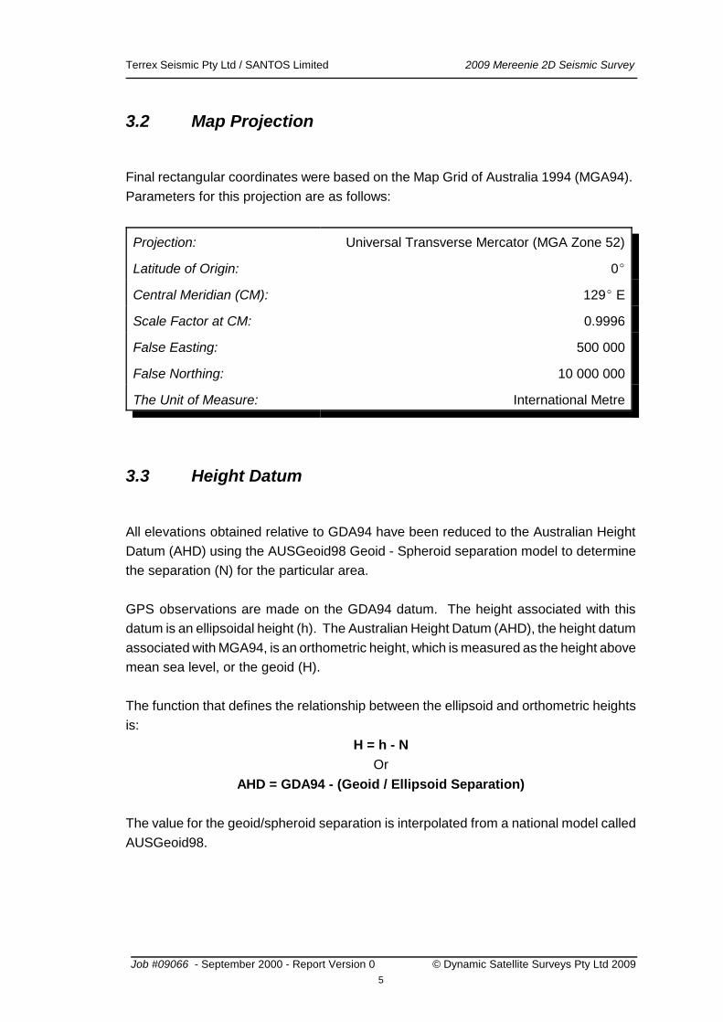
3.2 Map Projection
Final rectangular coordinates were based on the Map Grid of Australia 1994 (MGA94).
Parameters for this projection are as follows:
Projection: Universal Transverse Mercator (MGA Zone 52)
Latitude of Origin: 0
Central Meridian (CM): 129 E
Scale Factor at CM: 0.9996
False Easting: 500 000
False Northing: 10 000 000
The Unit of Measure: International Metre
3.3 Height Datum
All elevations obtained relative to GDA94 have been reduced to the Australian Height
Datum (AHD) using the AUSGeoid98 Geoid - Spheroid separation model to determine
the separation (N) for the particular area.
GPS observations are made on the GDA94 datum. The height associated with this
datum is an ellipsoidal height (h). The Australian Height Datum (AHD), the height datum
associated with MGA94, is an orthometric height, which is measured as the height above
mean sea level, or the geoid (H).
The function that defines the relationship between the ellipsoid and orthometric heights
is:
H = h - N
Or
AHD = GDA94 - (Geoid / Ellipsoid Separation)
The value for the geoid/spheroid separation is interpolated from a national model called
AUSGeoid98.
Job #09066 - September 2000 - Report Version 0 © Dynamic Satellite Surveys Pty Ltd 2009
5

Terrex Seismic Pty Ltd / SANTOS Limited 2009 Mereenie 2D Seismic Survey
AUSGeoid98 is the third in a series of national geoid models produced for Australia by
the Australian Surveying and Land Information Group (AUSLIG). The geoid-ellipsoid
data is prepared for the Australian region from:
- EGM96 Global Geopotential Model;
- 1996 Australian Gravity DataBase, from the Australian Geological Survey
Organisation (AGSO);
- AUSLIG / AGSO GEODATA nine-second digital elevation model;
- Satellite altimeter - derived free air gravity anomalies offshore;
- Theories, techniques and software developed by Associate Professor Will
Featherstone, Curtin University of Technology1.
AUSGeoid98 N values were interpolated using the GrafNet Version 7.60 software,
distributed by Waypoint Consulting Inc.
1Johnston, G.M., Featherstone, W.E. (1998) AUSGeoid98: A New Gravimetric Model for Australia
Job #09066 - September 2000 - Report Version 0 © Dynamic Satellite Surveys Pty Ltd 2009
6
Terrex Seismic Pty Ltd / SANTOS Limited 2009 Mereenie 2D Seismic Survey
4
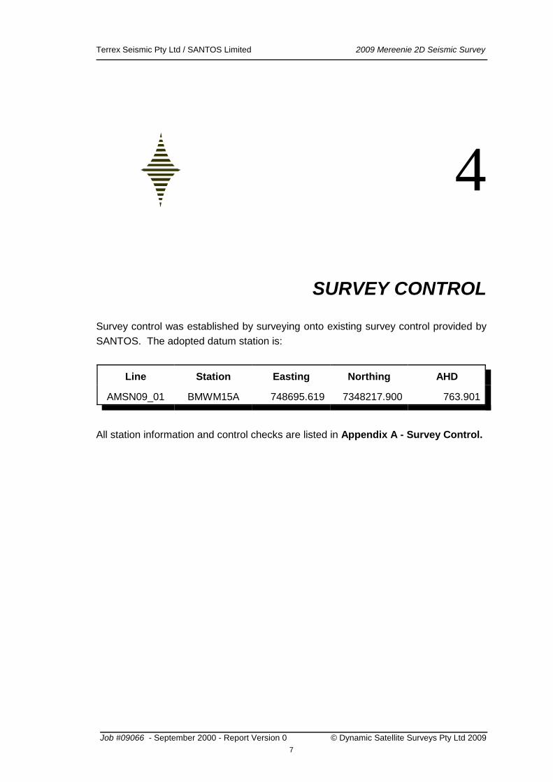
SURVEY CONTROL
Survey control was established by surveying onto existing survey control provided by
SANTOS. The adopted datum station is:
Line Station Easting Northing AHD
AMSN09_01 BMWM15A 748695.619 7348217.900 763.901
All station information and control checks are listed in Appendix A - Survey Control.
Job #09066 - September 2000 - Report Version 0 © Dynamic Satellite Surveys Pty Ltd 2009
7
Terrex Seismic Pty Ltd / SANTOS Limited 2009 Mereenie 2D Seismic Survey
5
MONUMENTATION
Line AMSN09_01 was pegged at ten (10) metre intervals.
All marks were wooden pegs. Every second peg was numbered on each side.
Permanent Markers were used for all GPS base stations. These consisted of a star
picket with associated tag stating Client, DSS Job Number and the unique Base ID.
Another star picket was placed at the base of the larger star picket to mark where the
station was surveyed.
Four (4) Environmental Monitoring Points (EMPs) were placed throughout the project.
These consist of a star picket with associated tag.
Permanent Markers were placed at the start and end of the Line. These consisted of a
star picket with associated tag.
Job #09066 - September 2000 - Report Version 0 © Dynamic Satellite Surveys Pty Ltd 2009
8
Terrex Seismic Pty Ltd / SANTOS Limited 2009 Mereenie 2D Seismic Survey
6
METHOD OF SURVEY
6.1 Line Preparation
DSS prepared the GPS unit for the line clearing operation on the first afternoon
immediately after mobilising onto site. The TC operators were familiar with the GPS
system used, and therefore had no problems clearing along the correct path. The line
followed a previous line (1987) and the clearing was completed very quickly.
Environmental Monitoring Points (EMPs) were established along the line at
predetermined positions prior to the dozer clearing the line.
The dozer was able to walk over most of the terrain with its blade up to minimise
environmental impact. This was a specific requirement of the Department of Natural
Resources, Environment, The Arts and Sport. There was no need for a grader to tidy
up the line after dozing.
Job #09066 - September 2000 - Report Version 0 © Dynamic Satellite Surveys Pty Ltd 2009
9
Terrex Seismic Pty Ltd / SANTOS Limited 2009 Mereenie 2D Seismic Survey
6.2 GPS Surveying
There are three modes of use in GPS surveying; static, kinematic and real-time
kinematic. On assessment, it was decided a real-time kinematic survey would best
enable position and elevation co-ordinates to be acquired in real-time and on the
appropriate datum. The survey was completed using DSS’ OEM4 real-time kinematic
(RTK) surveying technique.
NovAtel real-time kinematic methods can achieve accuracies of better than +/-0.05m in
position and elevation, depending on base line length. The expected precision for
locating pegged positions is better than 0.3 metres and is generally better than 0.2
metres.
Initialisation of the OEMV-3 rover GPS usually takes as little as one minute, although this
is greatly dependant on satellite geometry, availability, and base line length.
Job #09066 - September 2000 - Report Version 0 © Dynamic Satellite Surveys Pty Ltd 2009
10
Terrex Seismic Pty Ltd / SANTOS Limited 2009 Mereenie 2D Seismic Survey
6.3 Processing and Quality Control
All survey data was immediately recorded internally on the Fujitsu XP Tablets and
subsequently downloaded to the office computer each evening.
Quality of the satellite data was monitored by careful examination of the various on-
screen quality control statistics produced by the Nav05 software. These checks on data
integrity are in the form of standard deviation (or sigma) values for Easting, Northing and
Height and are generally better than 0.05 metres.
Any recording of positions where the standard deviation values exceeded 0.1 m was
highlighted to the surveyor at the time of recording. Following this, it was possible to re-
initialise the GPS in order to obtain a more accurate solution. Any recorded position
falling outside the required tolerances are flagged for further investigation and re-
recording if necessary.
Numerous checks on pre-recorded marks were observed during each days survey in
order to confirm the integrity of the GPS base receiver and the placed markers.
Coordinates were also checked in the office by determining point to point direction and
distance. Profile plots were examined in detail to identify any height anomalies. Any
points showing unusual position or height details were flagged and checked in the field.
Job #09066 - September 2000 - Report Version 0 © Dynamic Satellite Surveys Pty Ltd 2009
11
Terrex Seismic Pty Ltd / SANTOS Limited 2009 Mereenie 2D Seismic Survey
7
DATA PRESENTATION
All line files were checked and finalised before the survey crew demobilised from the
prospect.
All final data was in UTM grid coordinate format on the MGA94 datum on the GRS80
reference spheroid. All elevations were on the Australian Height Datum (AHD71).
Final data produced were:
EMPs
*.PDF - diagram of each EMP placed
EMPs.txt - text file of EMP locations
GoogleEarth
*.kmz - Google Earth file of final line location
Photos
*.JPG - project photographs
Survey Data
*.SEG - text files of all line data in SEGP1 format
*.UKA text files of all line data in UKOOA format
Trace Diagrams - PDF files for each line.
All files are backed up on digital disks in the Yeppoon office for future reference.
No hard copy data were provided.
Job #09066 - September 2000 - Report Version 0 © Dynamic Satellite Surveys Pty Ltd 2009
12
Terrex Seismic Pty Ltd / SANTOS Limited 2009 Mereenie 2D Seismic Survey
8
SAFETY
DSS personnel are aware of safety conditions concerning all exploration seismic surveys.
The DSS “Quality Policy Statement” and “Health, Safety and Environment Policy”
were adhered to at all times.
DSS received copies of Santos’ TSS (18-09-2009) and the Santos Induction Manual for
Mereenie Field (17-09-2009). A copy of the Best Practice Seismic Survey Guide (25-
102007) was also used as an aid in line preparation.
Each vehicle was fitted with a phone (NextG or Satellite), UHF radio, shovel, first-aid kit,
dry powder and water fire extinguishers, vehicle recovery equipment, rotating beacon
and weekly vehicle maintenance check lists.
Staying in contact with the Terrex Contracting Crew whilst mobilising to site was also
enforced and we made a point of enforcing journey management by calling ahead to the
SANTOS site office prior to leaving Alice Springs, and calling the site office upon arrival
back in Alice Springs after finishing the job.
There were no safety issues on this job.
Job #09066 - September 2000 - Report Version 0 © Dynamic Satellite Surveys Pty Ltd 2009
13
Terrex Seismic Pty Ltd / SANTOS Limited 2009 Mereenie 2D Seismic Survey
9
OPERATIONAL ASPECTS
Upon arriving at the Mereenie Oil Field on the 24th September, an Induction for DSS and
Terrex Contracting personnel was carried out. This involved a brief SANTOS induction
and a longer Department of Natural Resources, Environment, The Arts and Sport
Induction, which focussed on the environmental impact of seismic lines.
Once this was complete, we were taken to the line. Well Site WM15 and the associated
pipeline crossing were pointed out.
The dozer was loaded with a Garmin GPS and the data checked on the line.
The next day four EMP points were established and line pegging commenced. Three
PM’s from previous seismic surveys were located and surveyed to ensure the
coordinates of these previous surveys were in terms of this survey.
Line pegging was completed on the 26th September.
At the time of survey, it was not certain which direction the line would be shot. Because
of this, two trace diagrams were provided. One trace diagram was produced heading
North, while the second alternative diagram headed South.
Steve demobilised from Mereenie on the 27th September to Alice Springs.
Job #09066 - September 2000 - Report Version 0 © Dynamic Satellite Surveys Pty Ltd 2009
14
Terrex Seismic Pty Ltd / SANTOS Limited 2009 Mereenie 2D Seismic Survey
10
CONCLUSIONS AND RECOMMENDATIONS
This was a very straightforward survey, with good cooperation from all SANTOS and
Terrex Contracting staff.
The accommodation and facilities at Mereenie were superb.
Signed,
Dynamic Satellite Surveys Pty Ltd
Steve WardleSenior Surveyor
Checked and edited by:
Denis WilliamsSurvey Support Manager
Job #09066 - September 2000 - Report Version 0 © Dynamic Satellite Surveys Pty Ltd 2009
15
Terrex Seismic Pty Ltd / SANTOS Limited 2009 Mereenie 2D Seismic Survey
11
APPENDICES
Job #09066 - September 2000 - Report Version 0 © Dynamic Satellite Surveys Pty Ltd 2009
16
Terrex Seismic Pty Ltd / SANTOS Limited 2009 Mereenie 2D Seismic Survey
Survey Control
Job #09066 - September 2000 - Report Version 0 © Dynamic Satellite Surveys Pty Ltd 2009
A - 1
Terrex Seismic Pty Ltd / SANTOS Limited 2009 Mereenie 2D Seismic Survey
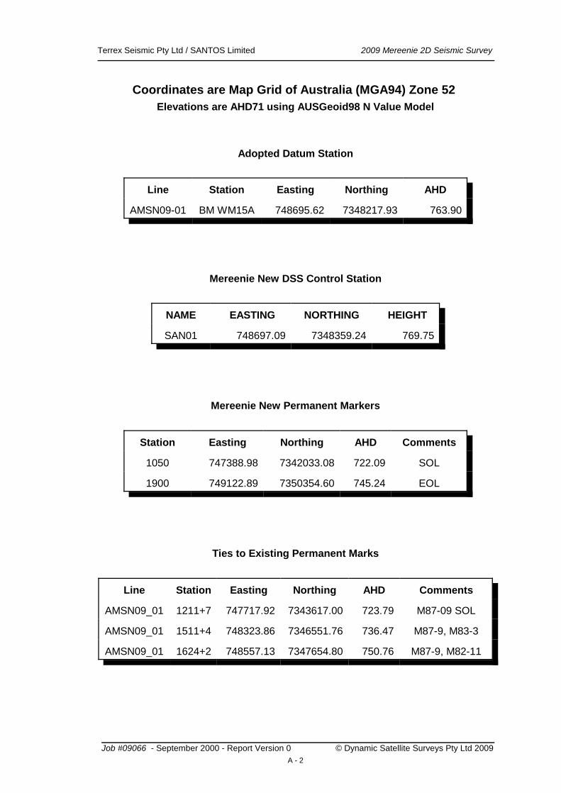
Coordinates are Map Grid of Australia (MGA94) Zone 52
Elevations are AHD71 using AUSGeoid98 N Value Model
Adopted Datum Station
Line Station Easting Northing AHD
AMSN09-01 BM WM15A 748695.62 7348217.93 763.90
Mereenie New DSS Control Station
NAME EASTING NORTHING HEIGHT
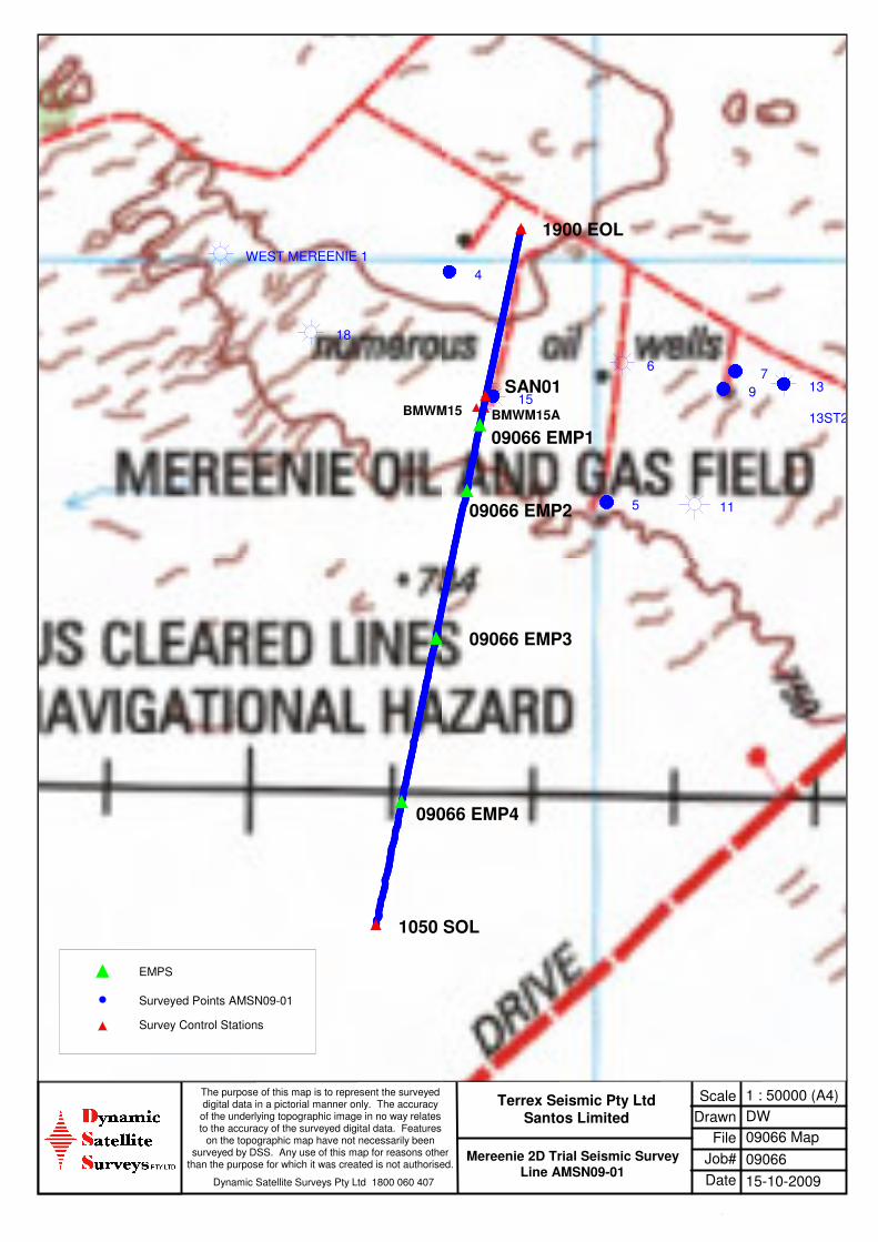
SAN01 748697.09 7348359.24 769.75
Mereenie New Permanent Markers
Station Easting Northing AHD Comments
1050 747388.98 7342033.08 722.09 SOL
1900 749122.89 7350354.60 745.24 EOL
Ties to Existing Permanent Marks
Line Station Easting Northing AHD Comments
AMSN09_01 1211+7 747717.92 7343617.00 723.79 M87-09 SOL
AMSN09_01 1511+4 748323.86 7346551.76 736.47 M87-9, M83-3
AMSN09_01 1624+2 748557.13 7347654.80 750.76 M87-9, M82-11
Job #09066 - September 2000 - Report Version 0 © Dynamic Satellite Surveys Pty Ltd 2009
A - 2
Terrex Seismic Pty Ltd / SANTOS Limited 2009 Mereenie 2D Seismic Survey
Project Map
Job #09066 - September 2000 - Report Version 0 © Dynamic Satellite Surveys Pty Ltd 2009
B - 1
No Window
Scale
Drawn
File
Job#
1 : 50000 (A4)
DW
09066 Map
09066
Date 15-10-2009
The purpose of this map is to represent the surveyeddigital data in a pictorial manner only. The accuracyof the underlying topographic image in no way relatesto the accuracy of the surveyed digital data. Features
on the topographic map have not necessarily beensurveyed by DSS. Any use of this map for reasons other
than the purpose for which it was created is not authorised.
Dynamic Satellite Surveys Pty Ltd 1800 060 407
Terrex Seismic Pty LtdSantos Limited
Mereenie 2D Trial Seismic SurveyLine AMSN09-01
13ST2
139
76
115
15
4
18
WEST MEREENIE 1
(((((((((((((((((((((
(((((((((((((((((((((((((((((((((((
((((((((((((((((((((((((((((((((((
((((((((((((
((((((((((((
(((((((((((((((((((((((((((((((((((((((((((((((((((((((((((
(((((((((((
(((((((((((
((((((((((((((((((((((((((((((((((
(((((((((((((((((((((((((((((((((((((((((((((((((((((((((((((((((((((((((((((((((((((((((((((((((((((((
((((((((((((
(((((((((((
(((((((((((((((((((((((((((((((((((((((((((((((((((((((((((((((((((((((((((((((((((((((((((((((((((((((((((((((((((
((((((((((((
((((((((((((((((((((((((((((((((((
(((((((((((
((((((((((((((((((((((((((((((((((
(((((((((((((((((((((((((((((((((((
((((((((((((
((((((((((((((((((((((((((((((((((
(((((((((((((((((((((((((((((((((((
((((((((((((((((((((((((((((((((((((((((((((((((((((((((((((((((((((((((((((((((((((((((((((((((((((((((
((((((((((((((((((((((((((((((((((((((((((((((((((((((((((
((((((((((((
f
f
f
f
f
f
f
BMWM15ABMWM15
09066 EMP2
09066 EMP3
09066 EMP1
09066 EMP4
SAN01
1050 SOL
1900 EOL
(
f
Survey Control Stations
Surveyed Points AMSN09-01
EMPS
Terrex Seismic Pty Ltd / SANTOS Limited 2009 Mereenie 2D Seismic Survey
Line Length Summary
Job #09066 - September 2000 - Report Version 0 © Dynamic Satellite Surveys Pty Ltd 2009
C - 1
Terrex Seismic Pty Ltd / SANTOS Limited 2009 Mereenie 2D Seismic Survey
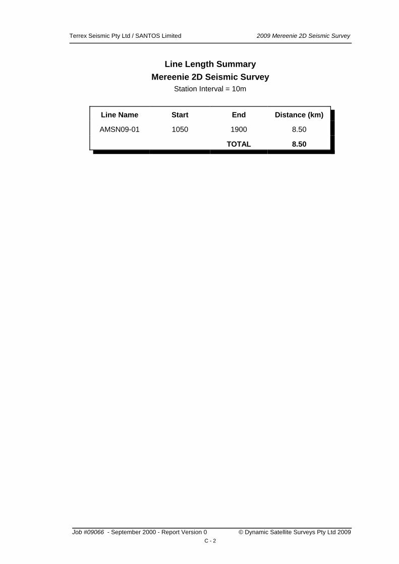
Line Length Summary
Mereenie 2D Seismic Survey
Station Interval = 10m
Line Name Start End Distance (km)
AMSN09-01 1050 1900 8.50
TOTAL 8.50
Job #09066 - September 2000 - Report Version 0 © Dynamic Satellite Surveys Pty Ltd 2009
C - 2

Terrex Seismic Pty Ltd / SANTOS Limited 2009 Mereenie 2D Seismic Survey
Environmental Monitoring Points (EMPs)
Job #09066 - September 2000 - Report Version 0 © Dynamic Satellite Surveys Pty Ltd 2009
D - 1
Terrex Seismic Pty Ltd / SANTOS Limited 2009 Mereenie 2D Seismic Survey
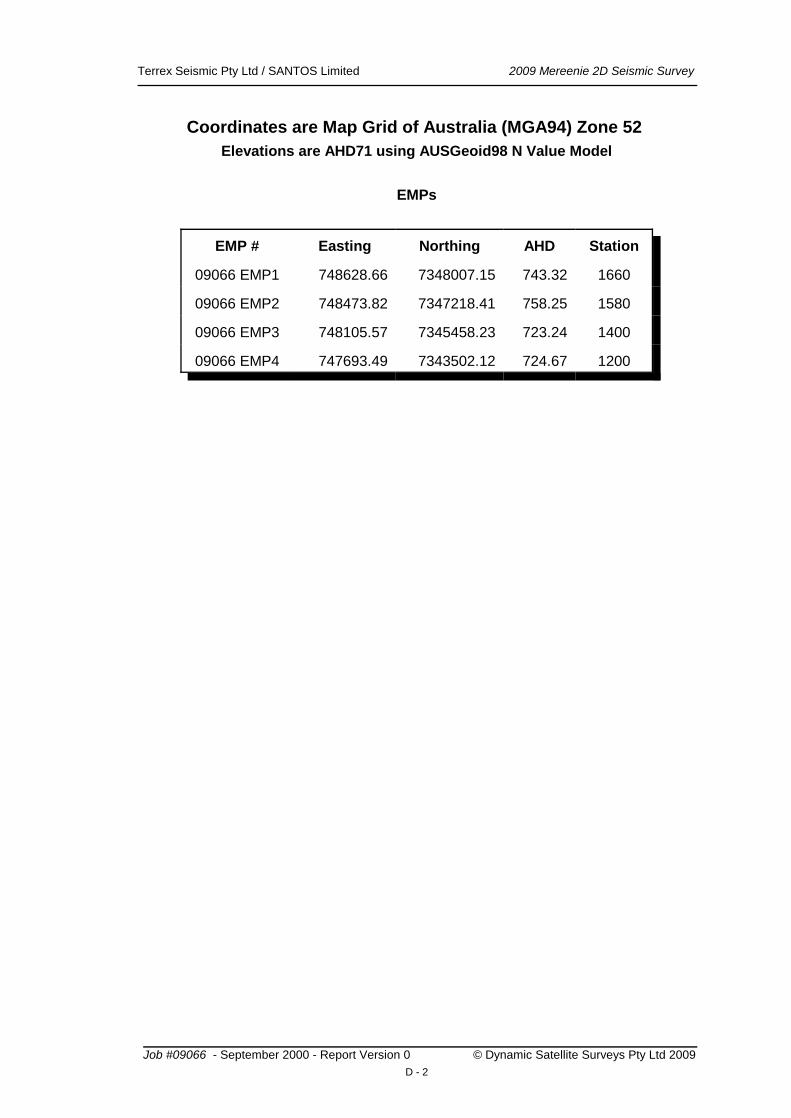
Coordinates are Map Grid of Australia (MGA94) Zone 52
Elevations are AHD71 using AUSGeoid98 N Value Model
EMPs
EMP # Easting Northing AHD Station
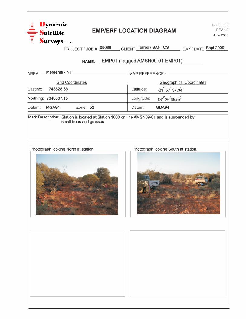
09066 EMP1 748628.66 7348007.15 743.32 1660
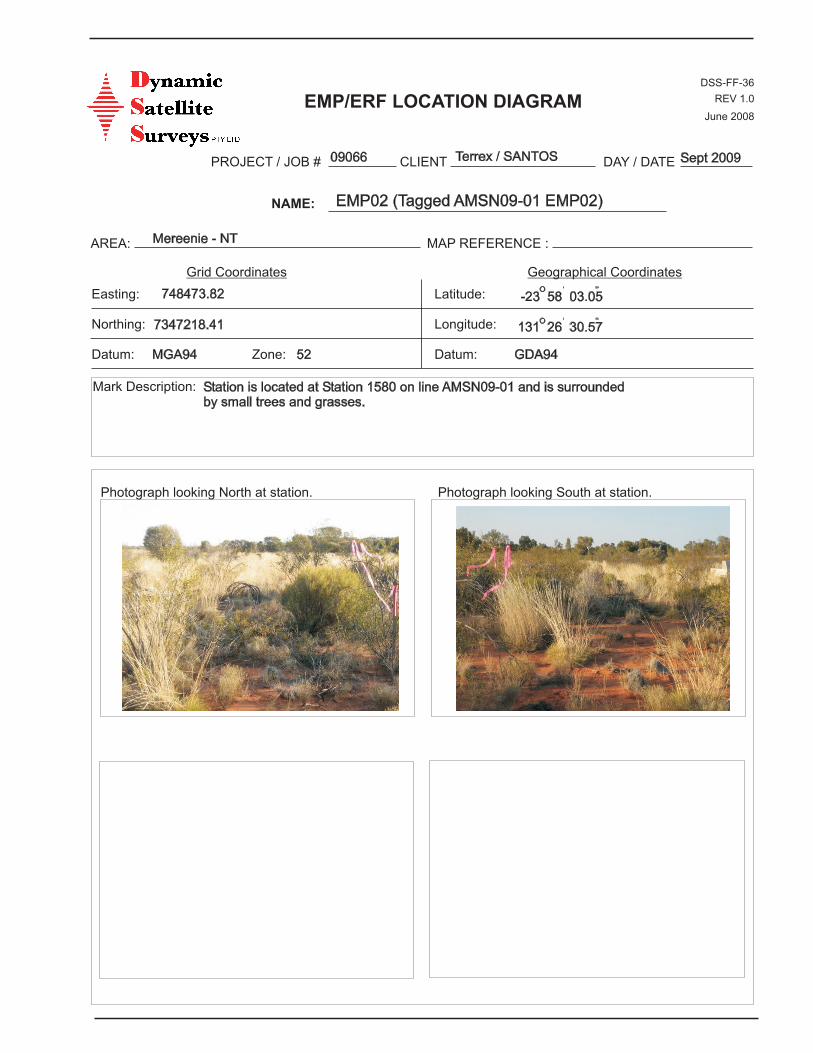
09066 EMP2 748473.82 7347218.41 758.25 1580
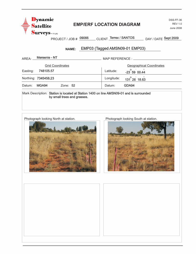
09066 EMP3 748105.57 7345458.23 723.24 1400
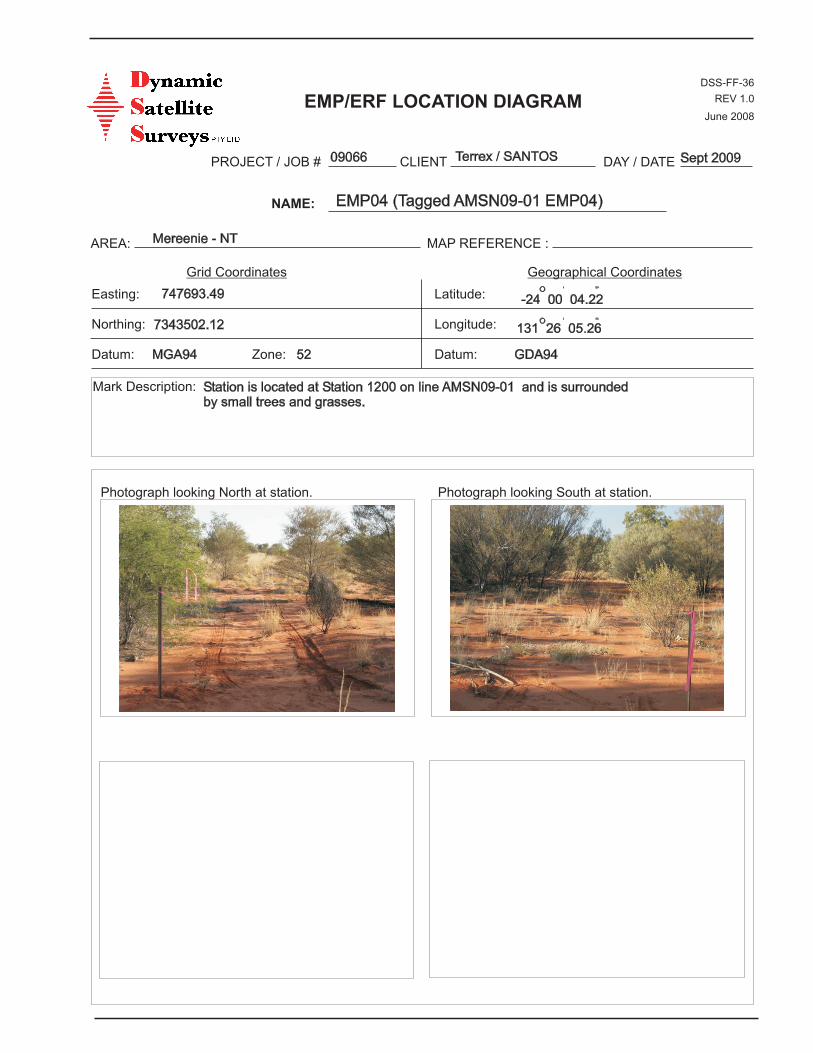
09066 EMP4 747693.49 7343502.12 724.67 1200
Job #09066 - September 2000 - Report Version 0 © Dynamic Satellite Surveys Pty Ltd 2009
D - 2
EMP/ERF LOCATION DIAGRAM
PROJECT / JOB # CLIENT DAY / DATE
NAME:
AREA:
Grid Coordinates
Easting:
Northing:
Zone:
Mark Description:
Geographical Coordinates
Latitude:
Longitude:
Datum:
MAP REFERENCE :
DSS-FF-36
REV 1.0
June 2008
Datum:
Photograph looking North at station. Photograph looking South at station.
O ‘ “
O ‘ “
GDA94
748628.66
MGA94
7348007.15
-23 57 37.34
131 26 35.57
52
Station is located at Station 1660 on line AMSN09-01 and is surrounded bysmall trees and grasses
Mereenie - NT
EMP01 (Tagged AMSN09-01 EMP01)
09066 Terrex / SANTOS Sept 2009
EMP/ERF LOCATION DIAGRAM
PROJECT / JOB # CLIENT DAY / DATE
NAME:
AREA:
Grid Coordinates
Easting:
Northing:
Zone:
Mark Description:
Geographical Coordinates
Latitude:
Longitude:
Datum:
MAP REFERENCE :
DSS-FF-36
REV 1.0
June 2008
Datum:
Photograph looking North at station. Photograph looking South at station.
O ‘ “
O ‘ “
GDA94
748473.82
MGA94
7347218.41 131 26 30.57
-23 58 03.05
52
Station is located at Station 1580 on line AMSN09-01 and is surroundedby small trees and grasses.
Mereenie - NT
EMP02 (Tagged AMSN09-01 EMP02)
09066 Terrex / SANTOS Sept 2009
EMP/ERF LOCATION DIAGRAM
PROJECT / JOB # CLIENT DAY / DATE
NAME:
AREA:
Grid Coordinates
Easting:
Northing:
Zone:
Mark Description:
Geographical Coordinates
Latitude:
Longitude:
Datum:
MAP REFERENCE :
DSS-FF-36
REV 1.0
June 2008
Datum:
Photograph looking North at station. Photograph looking South at station.
O ‘ “
O ‘ “
GDA94
748105.57
MGA94
7345458.23 131 26 18.63
52
Station is located at Station 1400 on line AMSN09-01 and is surroundedby small trees and grasses.
Mereenie - NT
EMP03 (Tagged AMSN09-01 EMP03)
09066 Terrex / SANTOS Sept 2009
-23 59 00.44
EMP/ERF LOCATION DIAGRAM
PROJECT / JOB # CLIENT DAY / DATE
NAME:
AREA:
Grid Coordinates
Easting:
Northing:
Zone:
Mark Description:
Geographical Coordinates
Latitude:
Longitude:
Datum:
MAP REFERENCE :
DSS-FF-36
REV 1.0
June 2008
Datum:
Photograph looking North at station. Photograph looking South at station.
O ‘ “
O ‘ “
GDA94
747693.49
MGA94
7343502.12 131 26 05.26
52
Station is located at Station 1200 on line AMSN09-01 and is surroundedby small trees and grasses.
Mereenie - NT
EMP04 (Tagged AMSN09-01 EMP04)
09066 Terrex / SANTOS Sept 2009
-24 00 04.22

Terrex Seismic Pty Ltd / SANTOS Limited 2009 Mereenie 2D Seismic Survey
Photographs
Job #09066 - September 2000 - Report Version 0 © Dynamic Satellite Surveys Pty Ltd 2009
E - 1
Terrex Seismic Pty Ltd / SANTOS Limited 2009 Mereenie 2D Seismic Survey
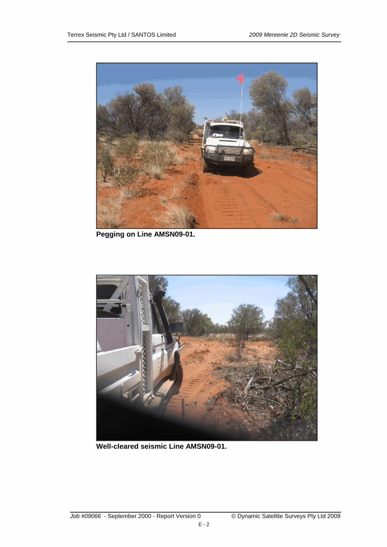
Pegging on Line AMSN09-01.
Well-cleared seismic Line AMSN09-01.
Job #09066 - September 2000 - Report Version 0 © Dynamic Satellite Surveys Pty Ltd 2009
E - 2

Terrex Seismic Pty Ltd / SANTOS Limited 2009 Mereenie 2D Seismic Survey
Job #09066 - September 2000 - Report Version 0 © Dynamic Satellite Surveys Pty Ltd 2009
F - 1
AndreaJ
TextBox
TRACE DIAGRAMS
PROJECT/JOB # CLIENT
PAGE OF AREA:
FROM STN TO STN SHOOTING DIRECTION: BEARING:o
SHOT INTERVAL: mSTN INTERVAL: m
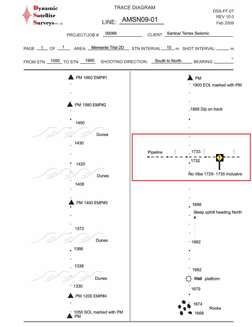
09066 Santos/ Terrex Seismic
1 Mereenie Trial 2D 10
South to North19001050
1
TRACE DIAGRAMDSS-FF-07
REV 10.0
Feb 2009LINE: AMSN09-01
1050 SOL marked with PM
Dunes
1338
1330
Dunes
1372
1366
Dunes
1420
1408
Dunes
1450
1430
1668
1674Rocks
2 Well2 Well platform
1679
1682
Steep uphill heading North
1682
1688
Pipeline
1732
1733
No Vibe 1729- 1735 Inclusive
1869 Dip on track
1900 EOL marked with PM
1200 EMP#4
1400 EMP#3
1580 EMP#2
1660 EMP#1
PM
PM
PM
PM
PM
PM
PROJECT/JOB # CLIENT
PAGE OF AREA:
FROM STN TO STN SHOOTING DIRECTION: BEARING:o
SHOT INTERVAL: mSTN INTERVAL: m
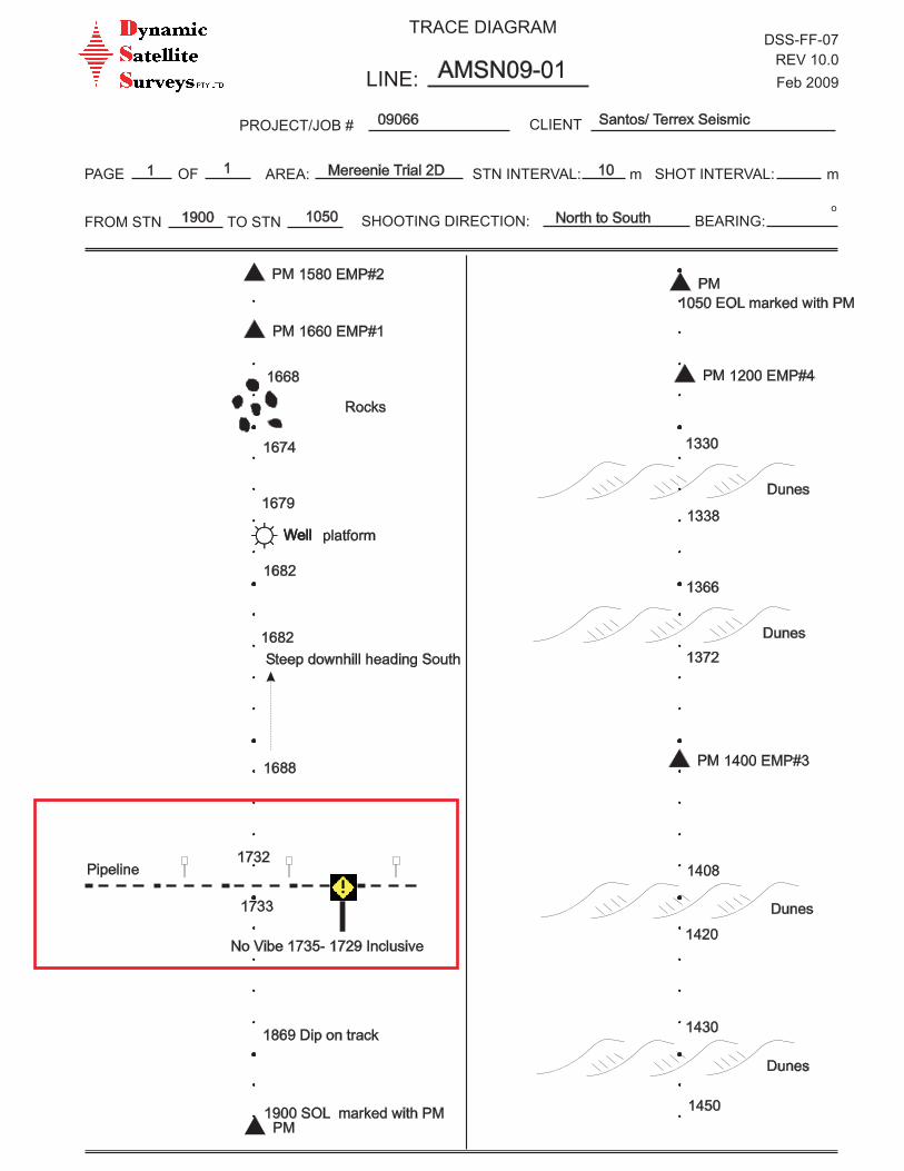
09066 Santos/ Terrex Seismic
1 Mereenie Trial 2D 10
North to South10501900
1
TRACE DIAGRAMDSS-FF-07
REV 10.0
Feb 2009LINE: AMSN09-01
1050 EOL marked with PM
Dunes
1338
1330
1200 EMP#4
1400 EMP#3
1580 EMP#2
1660 EMP#1
Dunes
1372
1366
Dunes
1420
1408
Dunes
1450
1430
1668
1674
Rocks
2 Well2 Well platform
1679
1682
Steep downhill heading South
1682
1688
Pipeline1732
1733
No Vibe 1735- 1729 Inclusive
1869 Dip on track
1900 SOL marked with PMPM
PM
PM
PM
PM
PM
APPENDIX 2 – TERREX SEISMIC FINAL OPERATIONS REPORT
MEREENIE 2D SEISMIC SURVEY TRIAL OL4 (SANTOS)
EP 115 (CENTRAL PETROLEUM)
CLIENT: SANTOS LTD
May 2011
PERTH OFFICE
L4 76 Kings Park Rd, West Perth WA 6005
T | 08 9235 4600
F | 08 9324 3640
BANYO OFFICE
22 Crockford Street, Banyo QLD 4014
T | 07 3621 0306
F | 07 3266 7345
OPERATIONS REPORT
FOR
SANTOS LTD
MEREENIE
2D SEISMIC SURVEY TRIAL
BY
DAVID KEAT
CREW # 402
SANTOS LTD MEREENIE 2D SEISMIC SURVEY TRIAL – MAY 2011 - FINAL REPORT
Page | i of i
Table of Contents PAGE
1. Introduction .....................................................................................................................................1
1.1 Geographic Area ........................................................................................................................................ 1
1.2 Climatic Conditions ................................................................................................................................... 1
1.3 Logistics ..................................................................................................................................................... 2
2. Surveying ...........................................................................................................................................3
2.1 Ranging/Chaining/Surveying ..................................................................................................................... 3
2.2 Line Clearing .............................................................................................................................................. 3
2.3 Permitting .................................................................................................................................................. 3
2.4 Shot Hole Drilling ....................................................................................................................................... 3
2.5 Explosives .................................................................................................................................................. 3
3. Recording/Processing ..................................................................................................................4
3.1 General Survey Details .............................................................................................................................. 4
3.2 Recording Parameters ............................................................................................................................... 4
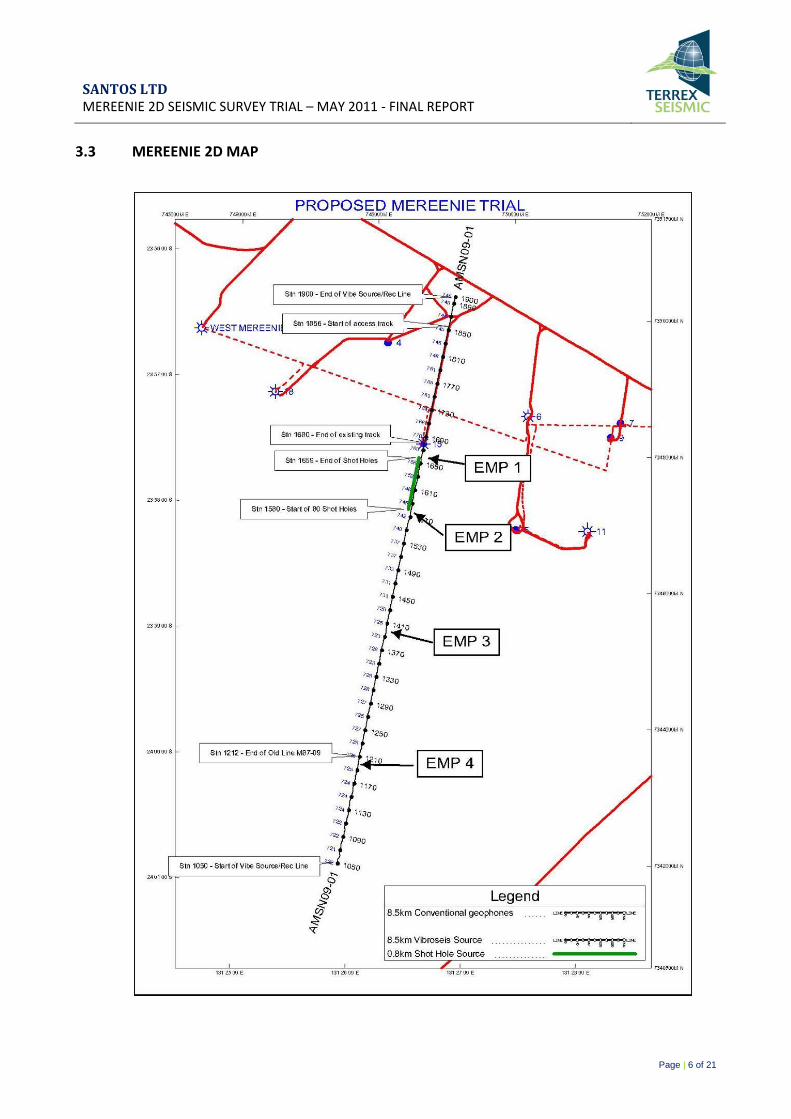
3.3 Mereenie 2D Map ..................................................................................................................................... 6
3.4 Recording .................................................................................................................................................. 7
3.5 Processing ................................................................................................................................................. 8
List of Appendices
Appendix A - Equipment Specifications .............................................................................................................................. 9
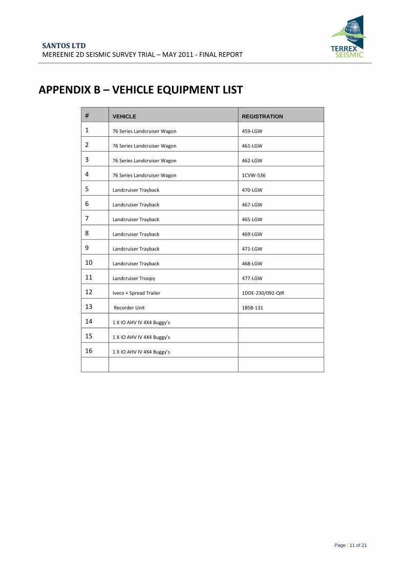
Appendix B – Vehicle Equipment List ............................................................................................................................... 11
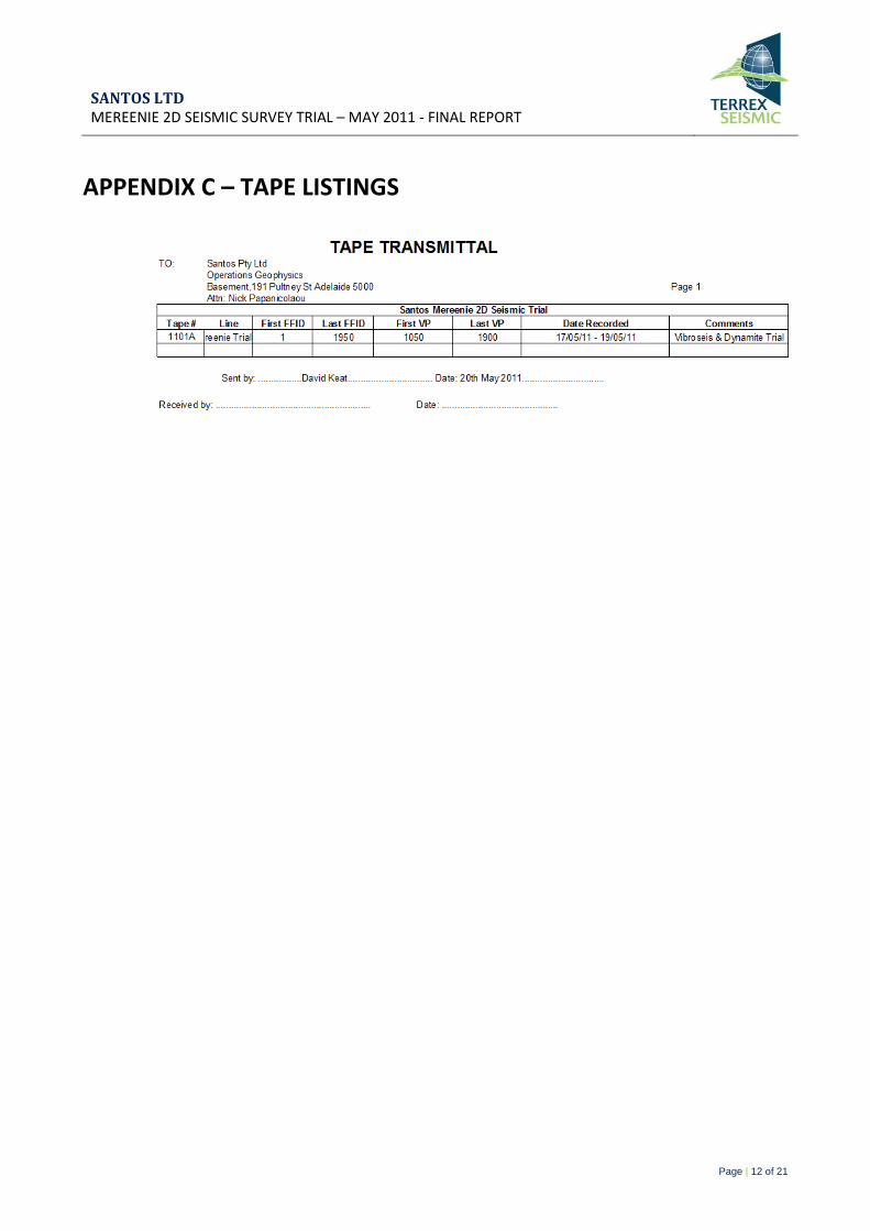
Appendix C – Tape Listings ............................................................................................................................................... 12
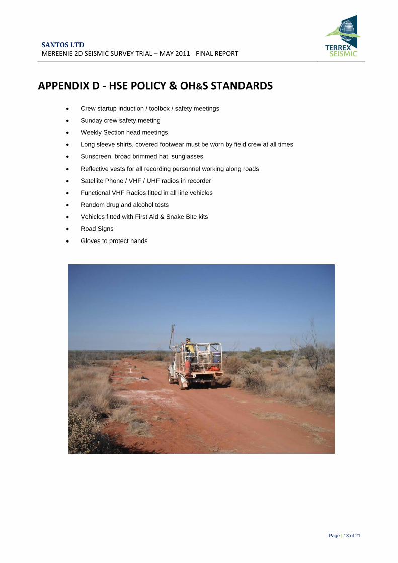
Appendix D - HSE Policy & OH&S Standards ..................................................................................................................... 13
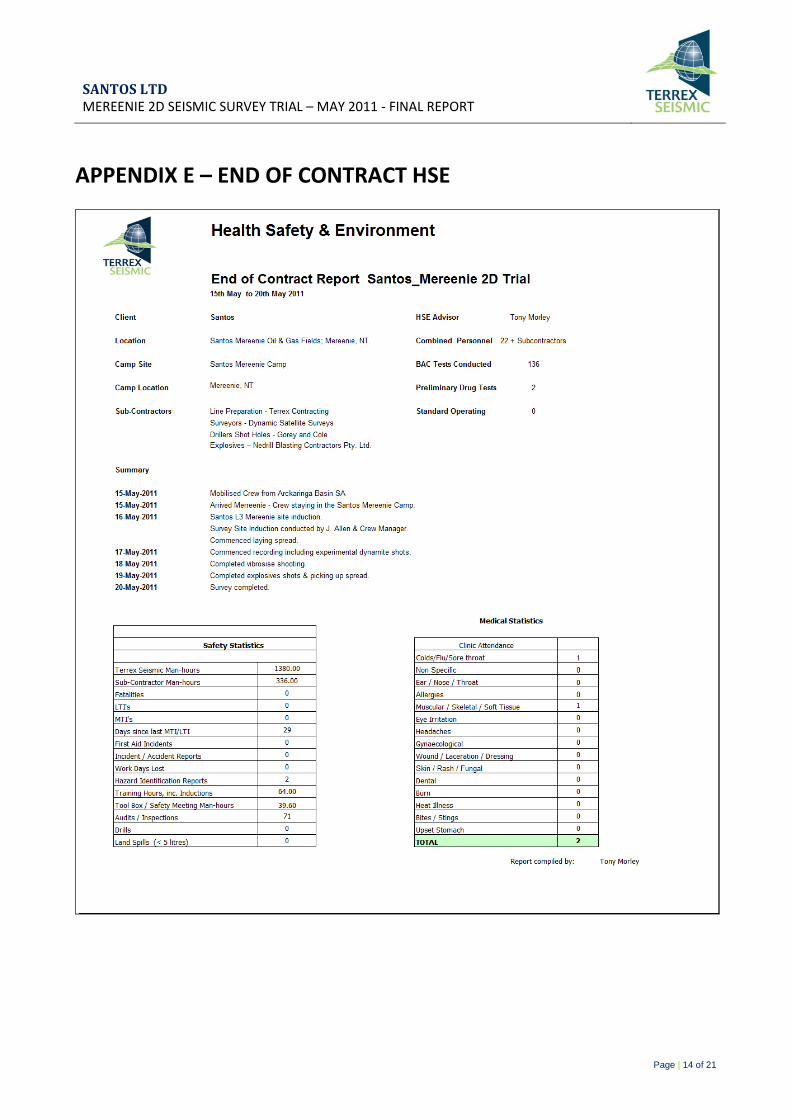
Appendix E – End of Contract HSE .................................................................................................................................... 14
Appendix F – Personnel Crew List ..................................................................................................................................... 15
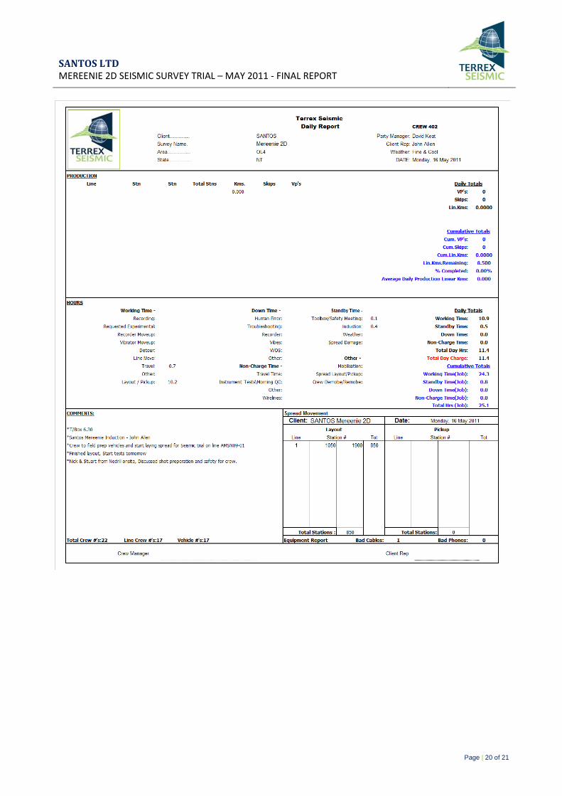
Appendix G – Daily Reports .............................................................................................................................................. 16
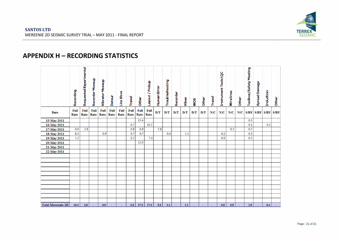
Appendix H – Recording Statistics .................................................................................................................................... 21
List of Photographs
Photograph 1 – Some of the local wildlife .......................................................................................................................... 1
Photograph 2 – Accommodation Facilities at Mereenie Camp .......................................................................................... 2
Photograph 3 – Recorder Truck .......................................................................................................................................... 3
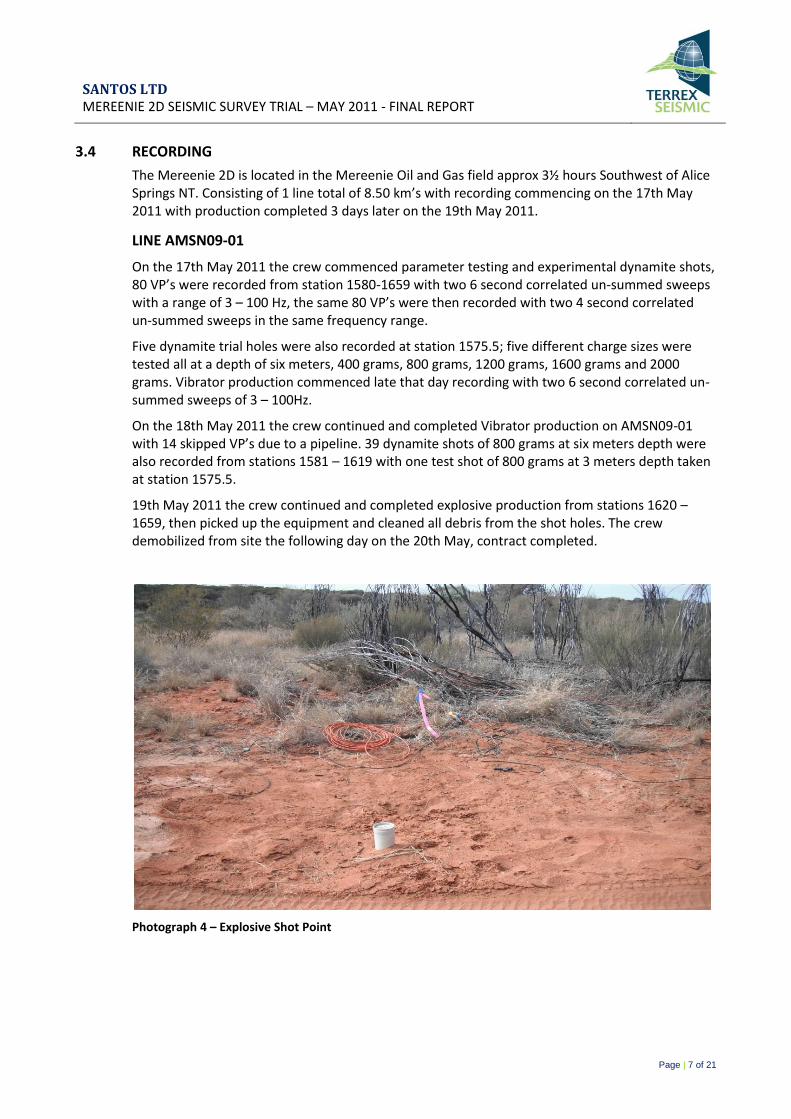
Photograph 4 – Explosive Shot Point .................................................................................................................................. 7
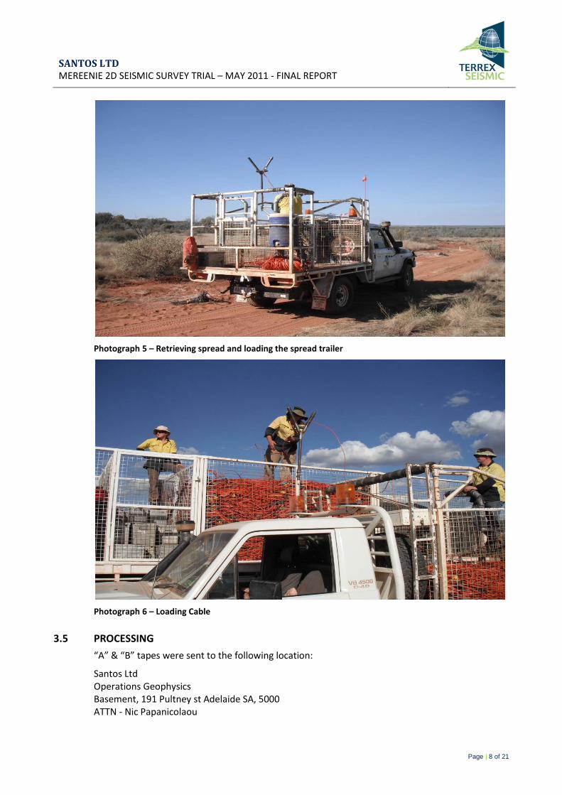
Photograph 5 – Retrieving spread and loading the spread trailer...................................................................................... 8
Photograph 6 – Loading Cable ............................................................................................................................................ 8
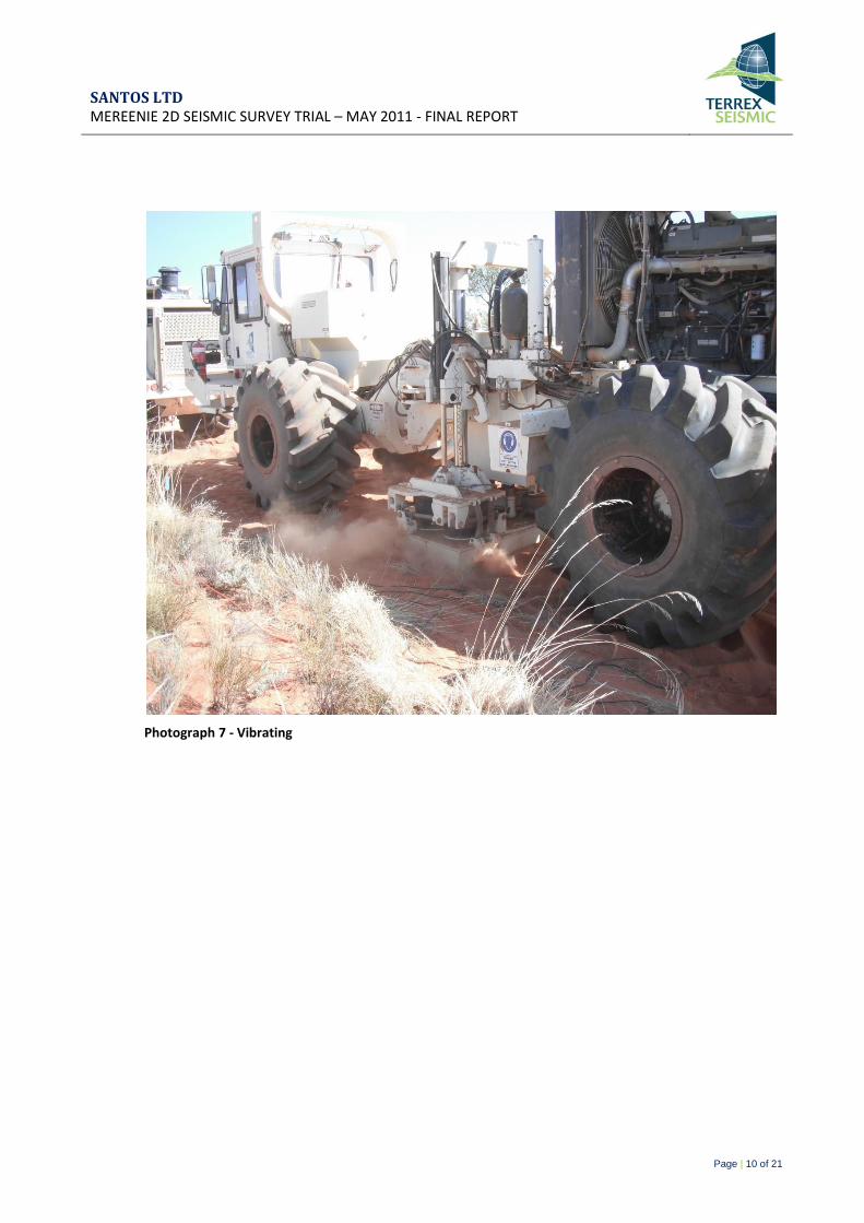
Photograph 7 - Vibrating .................................................................................................................................................. 10
SANTOS LTD MEREENIE 2D SEISMIC SURVEY TRIAL – MAY 2011 - FINAL REPORT
Page | 1 of 21
1. INTRODUCTION
Terrex Seismic was contracted by Santos to conduct the Mereenie 2D Seismic Survey Trial.
Recording commenced on the 17th May 2011 and was completed on the 19th May 2011.
1.1 GEOGRAPHIC AREA
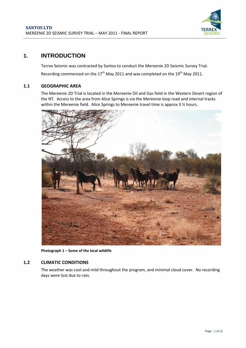
The Mereenie 2D Trial is located in the Mereenie Oil and Gas field in the Western Desert region of the NT. Access to the area from Alice Springs is via the Mereenie loop road and internal tracks within the Mereenie field. Alice Springs to Mereenie travel time is approx 3 ½ hours.
Photograph 1 – Some of the local wildlife
1.2 CLIMATIC CONDITIONS
The weather was cool and mild throughout the program, and minimal cloud cover. No recording days were lost due to rain.
SANTOS LTD MEREENIE 2D SEISMIC SURVEY TRIAL – MAY 2011 - FINAL REPORT
Page | 2 of 21
1.3 LOGISTICS
The crew mobilized on the 15th May 2011 from the Arckaringa Basin SA off the Oodnadatta Track, Mobe completed in one day with no break downs or down time. The crew arrived at Mereenie Oil field NT late afternoon.
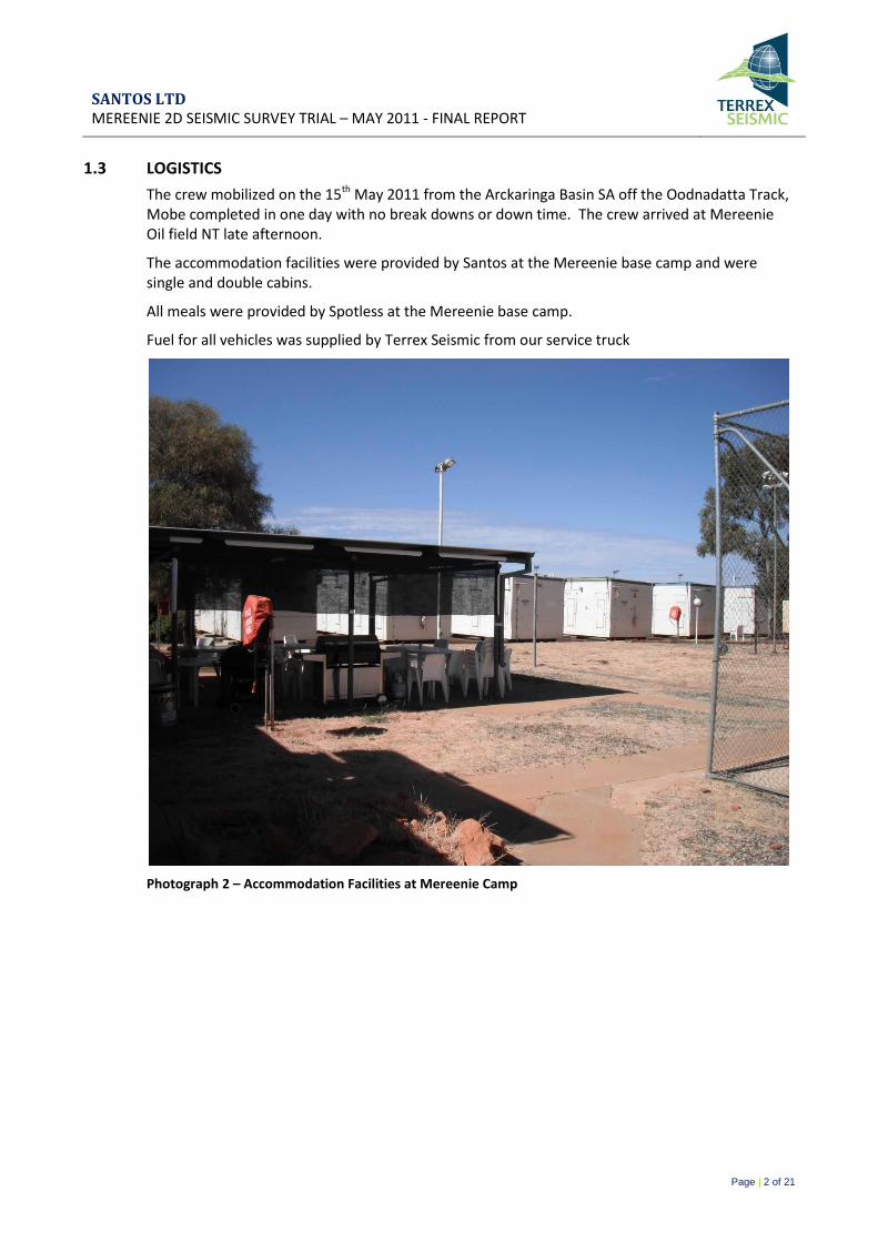
The accommodation facilities were provided by Santos at the Mereenie base camp and were single and double cabins.
All meals were provided by Spotless at the Mereenie base camp.
Fuel for all vehicles was supplied by Terrex Seismic from our service truck
Photograph 2 – Accommodation Facilities at Mereenie Camp
SANTOS LTD MEREENIE 2D SEISMIC SURVEY TRIAL – MAY 2011 - FINAL REPORT
Page | 3 of 21
2. SURVEYING
2.1 RANGING/CHAINING/SURVEYING
Line chaining and survey for the entire program was completed by Dynamic Satellite Survey personnel from Yeppoon Queensland.
2.2 LINE CLEARING
All line clearing was performed by Santos.
2.3 PERMITTING
Permitting was carried out by the client with John Allen acting as the client representative until completion of the survey.
2.4 SHOT HOLE DRILLING
Shot hole drilling services were carried out by Gory and Cole Drilling of Alice Springs.
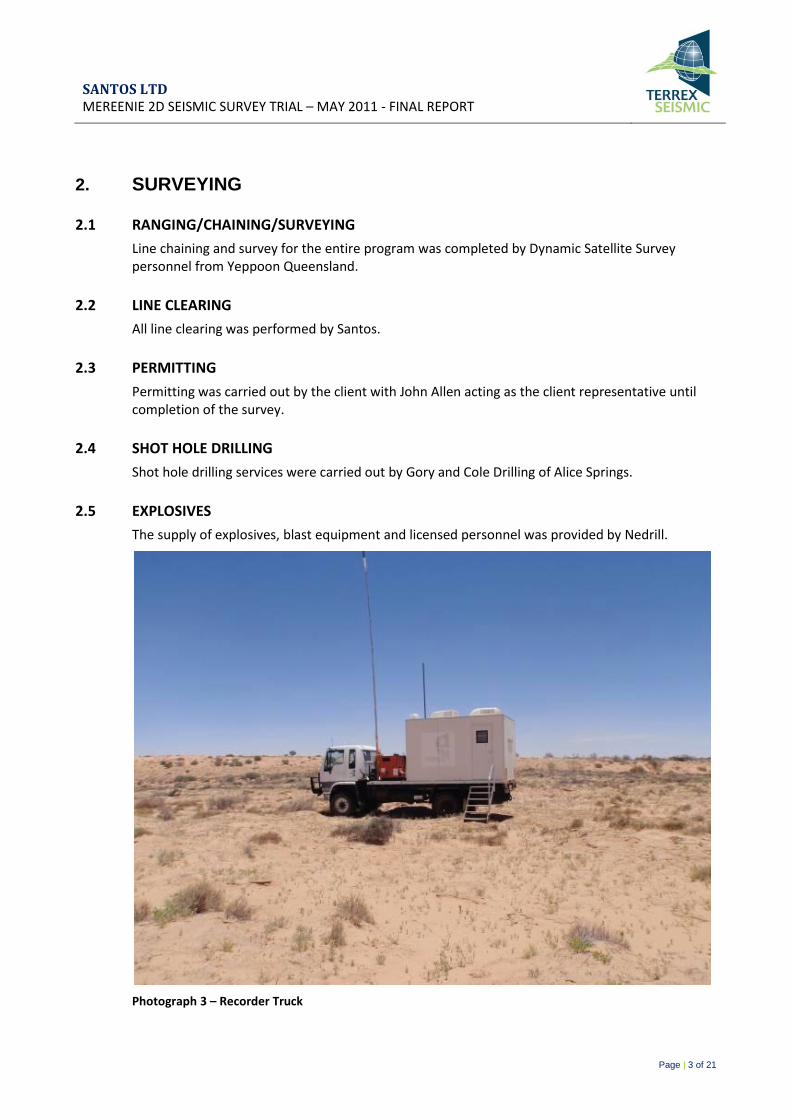
2.5 EXPLOSIVES
The supply of explosives, blast equipment and licensed personnel was provided by Nedrill.
Photograph 3 – Recorder Truck
SANTOS LTD MEREENIE 2D SEISMIC SURVEY TRIAL – MAY 2011 - FINAL REPORT
Page | 4 of 21
3. RECORDING/PROCESSING
3.1 GENERAL SURVEY DETAILS
Survey 2011 Mereenie 2D Seismic Survey Trial - OL4, EP115
Lines AMSN09-01
Areas Mereenie NT
3.2 RECORDING PARAMETERS
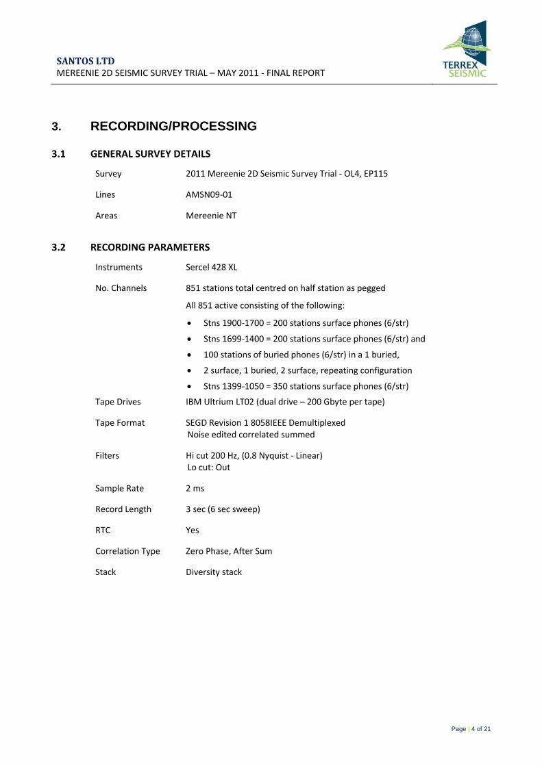
Instruments Sercel 428 XL
No. Channels 851 stations total centred on half station as pegged
All 851 active consisting of the following:
Stns 1900-1700 = 200 stations surface phones (6/str)
Stns 1699-1400 = 200 stations surface phones (6/str) and
100 stations of buried phones (6/str) in a 1 buried,
2 surface, 1 buried, 2 surface, repeating configuration
Stns 1399-1050 = 350 stations surface phones (6/str)
Tape Drives IBM Ultrium LT02 (dual drive – 200 Gbyte per tape)
Tape Format SEGD Revision 1 8058IEEE Demultiplexed Noise edited correlated summed
Filters Hi cut 200 Hz, (0.8 Nyquist - Linear) Lo cut: Out
Sample Rate 2 ms
Record Length 3 sec (6 sec sweep)
RTC Yes
Correlation Type Zero Phase, After Sum
Stack Diversity stack
SANTOS LTD MEREENIE 2D SEISMIC SURVEY TRIAL – MAY 2011 - FINAL REPORT
Page | 5 of 21
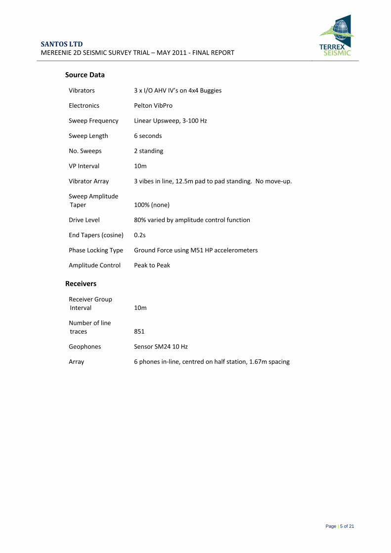
Source Data
Vibrators 3 x I/O AHV IV’s on 4x4 Buggies
Electronics Pelton VibPro
Sweep Frequency Linear Upsweep, 3-100 Hz
Sweep Length 6 seconds
No. Sweeps 2 standing
VP Interval 10m
Vibrator Array 3 vibes in line, 12.5m pad to pad standing. No move-up.
Sweep Amplitude Taper 100% (none)
Drive Level 80% varied by amplitude control function
End Tapers (cosine) 0.2s
Phase Locking Type Ground Force using M51 HP accelerometers
Amplitude Control Peak to Peak
Receivers
Receiver Group Interval 10m
Number of line traces 851
Geophones Sensor SM24 10 Hz
Array 6 phones in-line, centred on half station, 1.67m spacing
SANTOS LTD MEREENIE 2D SEISMIC SURVEY TRIAL – MAY 2011 - FINAL REPORT
Page | 6 of 21
3.3 MEREENIE 2D MAP
SANTOS LTD MEREENIE 2D SEISMIC SURVEY TRIAL – MAY 2011 - FINAL REPORT
Page | 7 of 21
3.4 RECORDING
The Mereenie 2D is located in the Mereenie Oil and Gas field approx 3½ hours Southwest of Alice Springs NT. Consisting of 1 line total of 8.50 km’s with recording commencing on the 17th May 2011 with production completed 3 days later on the 19th May 2011.
LINE AMSN09-01
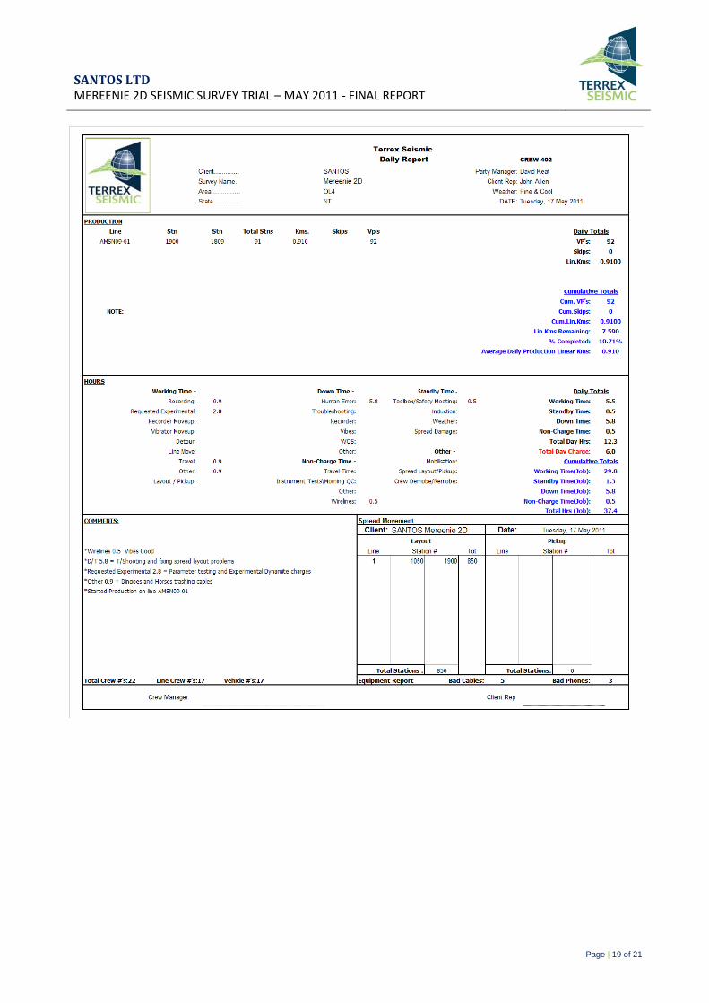
On the 17th May 2011 the crew commenced parameter testing and experimental dynamite shots, 80 VP’s were recorded from station 1580-1659 with two 6 second correlated un-summed sweeps with a range of 3 – 100 Hz, the same 80 VP’s were then recorded with two 4 second correlated un-summed sweeps in the same frequency range.
Five dynamite trial holes were also recorded at station 1575.5; five different charge sizes were tested all at a depth of six meters, 400 grams, 800 grams, 1200 grams, 1600 grams and 2000 grams. Vibrator production commenced late that day recording with two 6 second correlated un-summed sweeps of 3 – 100Hz.
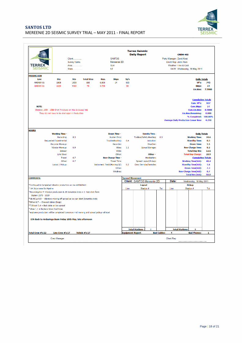
On the 18th May 2011 the crew continued and completed Vibrator production on AMSN09-01 with 14 skipped VP’s due to a pipeline. 39 dynamite shots of 800 grams at six meters depth were also recorded from stations 1581 – 1619 with one test shot of 800 grams at 3 meters depth taken at station 1575.5.
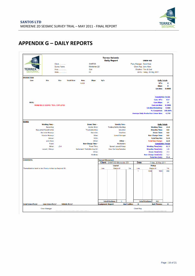
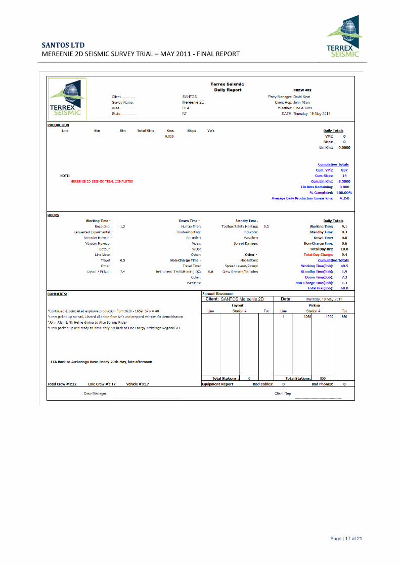
19th May 2011 the crew continued and completed explosive production from stations 1620 – 1659, then picked up the equipment and cleaned all debris from the shot holes. The crew demobilized from site the following day on the 20th May, contract completed.
Photograph 4 – Explosive Shot Point
SANTOS LTD MEREENIE 2D SEISMIC SURVEY TRIAL – MAY 2011 - FINAL REPORT
Page | 8 of 21
Photograph 5 – Retrieving spread and loading the spread trailer
Photograph 6 – Loading Cable
3.5 PROCESSING
“A” & “B” tapes were sent to the following location:
Santos Ltd Operations Geophysics Basement, 191 Pultney st Adelaide SA, 5000 ATTN - Nic Papanicolaou

SANTOS LTD MEREENIE 2D SEISMIC SURVEY TRIAL – MAY 2011 - FINAL REPORT
Page | 9 of 21
APPENDIX A - EQUIPMENT SPECIFICATIONS
SEISMIC ACQUISITION CREW - EQUIPMENT
RECORDING EQUIPMENT, SOURCE EQUIPMENT
RECORDING EQUIPMENT (2D Surveys)
SERCEL 428 Seismic Data Acquisition System
Three (4) 19inch Flat Screens with Sun Blade Computer
Veritas V12 Plotter, UPS, LIM, APM
Two (2) LTO High Density Tape Drives
Two Hundred and Twenty Five Seismic Cables with 4 x FDU’s per cable (900 Channels)
Power Harness Leads
Line Batteries
Transverse Cables
Repeaters
LAUX’s
LAUL’s
Telwin (Nevaboost 140) Battery Chargers
Pelton Real Time Similarity System
One (1) 10 metre 6 DB Boost High Gain Antenna on Recording Truck
Sensor SM4 10Hz High Specification Super phones
Eight Hundred & Fifty (850) Geophone strings with 6 ph/group
Note: Terrex Seismic warrants that 90% of equipment will be used in field and up to 10% may be undergoing repair and maintenance.
SOURCE EQUIPMENT
Three (3) Input-Output AVH IV 4x4 Buggy Vibrators:
Peak force is 62000lbs per Vibe and Hold-Down weight is 62400lbs per Vibe
Three (3) Pelton VibPro Vibrator Control Electronics
One (1) Pelton VibPro Encoder Sweep Generator for Recorder
Three (3) operating Online
Electronics are capable of Trade Marked Varisweep
SANTOS LTD MEREENIE 2D SEISMIC SURVEY TRIAL – MAY 2011 - FINAL REPORT
Page | 10 of 21
Photograph 7 - Vibrating
SANTOS LTD MEREENIE 2D SEISMIC SURVEY TRIAL – MAY 2011 - FINAL REPORT
Page | 11 of 21
APPENDIX B – VEHICLE EQUIPMENT LIST
# VEHICLE REGISTRATION
1 76 Series Landcruiser Wagon 459-LGW
2 76 Series Landcruiser Wagon 461-LGW
3 76 Series Landcruiser Wagon 462-LGW
4 76 Series Landcruiser Wagon 1CVW-536
5 Landcruiser Trayback 470-LGW
6 Landcruiser Trayback 467-LGW
7 Landcruiser Trayback 465-LGW
8 Landcruiser Trayback 469-LGW
9 Landcruiser Trayback 471-LGW
10 Landcruiser Trayback 468-LGW
11 Landcruiser Troopy 477-LGW
12 Iveco + Spread Trailer 1DDE-230/092-QIR
13 Recorder Unit 1BSB-131
14 1 X IO AHV IV 4X4 Buggy’s
15 1 X IO AHV IV 4X4 Buggy’s
16 1 X IO AHV IV 4X4 Buggy’s
SANTOS LTD MEREENIE 2D SEISMIC SURVEY TRIAL – MAY 2011 - FINAL REPORT
Page | 12 of 21
APPENDIX C – TAPE LISTINGS
SANTOS LTD MEREENIE 2D SEISMIC SURVEY TRIAL – MAY 2011 - FINAL REPORT
Page | 13 of 21
APPENDIX D - HSE POLICY & OH&S STANDARDS
Crew startup induction / toolbox / safety meetings
Sunday crew safety meeting
Weekly Section head meetings
Long sleeve shirts, covered footwear must be worn by field crew at all times
Sunscreen, broad brimmed hat, sunglasses
Reflective vests for all recording personnel working along roads
Satellite Phone / VHF / UHF radios in recorder
Functional VHF Radios fitted in all line vehicles
Random drug and alcohol tests
Vehicles fitted with First Aid & Snake Bite kits
Road Signs
Gloves to protect hands
SANTOS LTD MEREENIE 2D SEISMIC SURVEY TRIAL – MAY 2011 - FINAL REPORT
Page | 14 of 21
APPENDIX E – END OF CONTRACT HSE

SANTOS LTD MEREENIE 2D SEISMIC SURVEY TRIAL – MAY 2011 - FINAL REPORT
Page | 15 of 21
APPENDIX F – PERSONNEL CREW LIST
# PERSONNEL POSITION
1 David Keat Crew Manager
2 Tony Morley Hse Advisor
3 Stuart Rauckman Vibe Tech
4 Nik Helme Observer
5 Nelson Castillo Observer
6 Steven Geisler Line Boss
7 Anthony Davidson Vibe Op
8 Luke Samios Vibe Op
9 Darrin Johnstone Vibe Op
10 Floyd Dyball Trouble Shooter
11 Brenton Amor Line Crew
12 Karan Gupta Line Crew
13 Kim Gibson Line Crew
14 Luke Hiscox Line Crew
15 Craig Jason Line Crew
16 Paul Jensen Line Crew
17 Shawn Laing Line Crew
18 Rangi Mace Line Crew
19 Neil Mcgill Line Crew
20 Tai Taimani Line Crew
21 Brenton Pearce Line Crew
22 Kara Pearce Line Crew
SANTOS LTD MEREENIE 2D SEISMIC SURVEY TRIAL – MAY 2011 - FINAL REPORT
Page | 16 of 21
APPENDIX G – DAILY REPORTS
SANTOS LTD MEREENIE 2D SEISMIC SURVEY TRIAL – MAY 2011 - FINAL REPORT
Page | 17 of 21
SANTOS LTD MEREENIE 2D SEISMIC SURVEY TRIAL – MAY 2011 - FINAL REPORT
Page | 18 of 21
SANTOS LTD MEREENIE 2D SEISMIC SURVEY TRIAL – MAY 2011 - FINAL REPORT
Page | 19 of 21
SANTOS LTD MEREENIE 2D SEISMIC SURVEY TRIAL – MAY 2011 - FINAL REPORT
Page | 20 of 21
SANTOS LTD MEREENIE 2D SEISMIC SURVEY TRIAL – MAY 2011 - FINAL REPORT
Page | 21 of 21
APPENDIX H – RECORDING STATISTICS

APPENDIX 3 - RECORDING PRODUCTION STATISTICS

SANTOS LTD MEREENIE 2D SEISMIC SURVEY TRIAL – MAY 2011 - FINAL REPORT
Page | 21 of 21
APPENDIX H – RECORDING STATISTICS

APPENDIX 4 - PERSONNEL LIST
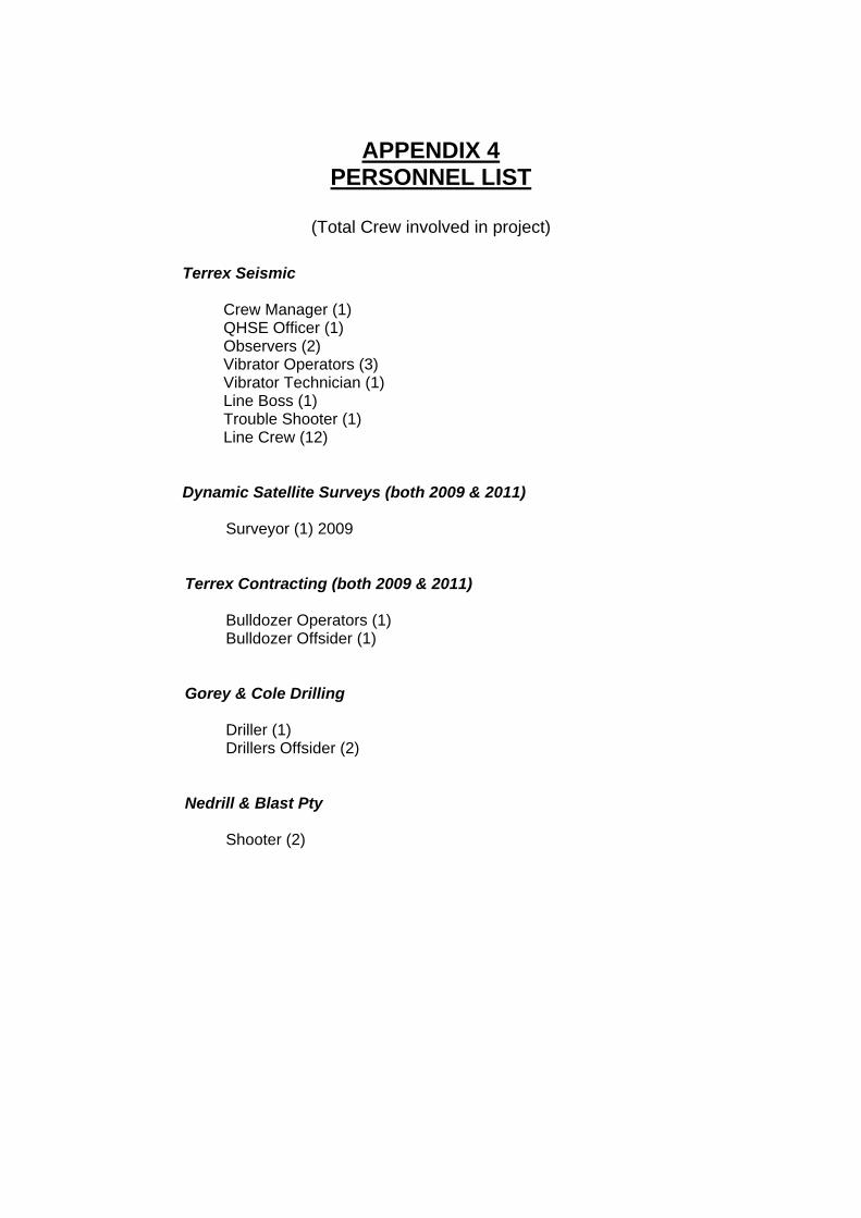
APPENDIX 4 PERSONNEL LIST
(Total Crew involved in project)
Terrex Seismic
Crew Manager (1) QHSE Officer (1) Observers (2) Vibrator Operators (3) Vibrator Technician (1) Line Boss (1) Trouble Shooter (1) Line Crew (12)
Dynamic Satellite Surveys (both 2009 & 2011) Surveyor (1) 2009
Terrex Contracting (both 2009 & 2011)
Bulldozer Operators (1) Bulldozer Offsider (1)
Gorey & Cole Drilling
Driller (1) Drillers Offsider (2)
Nedrill & Blast Pty
Shooter (2)

APPENDIX 5 – DRILLING PRODUCTION
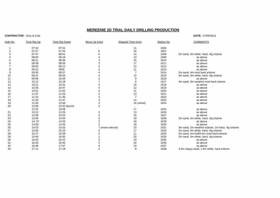
MEREENIE 2D TRIAL DAILY DRILLING PRODUCTION
CONTRACTOR: Gory & Cole DATE: 07/05/2011
Hole No. Time Rig Up Time Rig Down Move Up (min) Elapsed Time (min) Station No COMMENTS
1 07:10 07:21 - 11 1606 2 07:27 07:43 6 16 1607 3 07:47 08:01 4 14 1608 2m sand, 4m white, hard, vfg s/stone 4 08:05 08:18 4 13 1609 as above 5 08:21 08:36 3 15 1610 as above 6 08:39 08:56 3 17 1611 as above 7 09:00 09:12 4 12 1612 as above 8 09:15 0926 3 11 1613 as above 9 09:30 09:37 4 7 1614 2m sand, 4m mod hard s/stone 10 09:41 09:53 4 12 1615 3m sand, 3m white, hard, vfg s/stone 11 09:56 10:05 3 9 1616 as above 12 10:12 10:18 7 6 1617 3m sand, 3m weathrd mod hard s/stone 13 10:21 10:31 3 10 1618 as above 14 10:35 10:47 4 12 1619 as above 15 10:51 11:02 4 11 1620 as above 16 11:07 11:20 5 13 1621 as above 17 11:23 11:30 3 7 1622 as above 18 11:33 11:47 3 14 1623 as above 19 11:50 12:06 3 16 (refuel) 1624 as above 20 12:09 12:52 (lunch) 3 - 12:52 13:09 17 1625 as above 21 13:12 13:25 3 13 1626 as above 22 13:28 13:43 3 15 1627 as above 23 13:46 14:04 3 18 1628 2m sand, 4m white, hard, vfg s/stone 24 14: 07 14:25 3 18 1629 as above 25 14:28 14:46 3 18 1630 as above 26 14:53 15:03 7 (move w/truck) 10 1631 3m sand, 2m weathrd s/stone, 1m hard, vfg s/stone 27 15:06 15:23 3 17 1632 2m sand, 4m white, hard, vfg s/stone 28 15:27 15:38 4 11 1633 2m sand, 4m buff/lt brn mod hard s/stone 29 15:40 16:00 2 20 1634 2m sand. 4m white, hard, vfg s/stone 30 16:03 16:22 3 19 1635 as above 31 16:25 16:45 3 20 1636 as above 32 16:48 17:07 3 19 1637 as above 33 17:11 17:19 4 8 1638 4.5m clayey sand, 1.5m white, hard s/stone
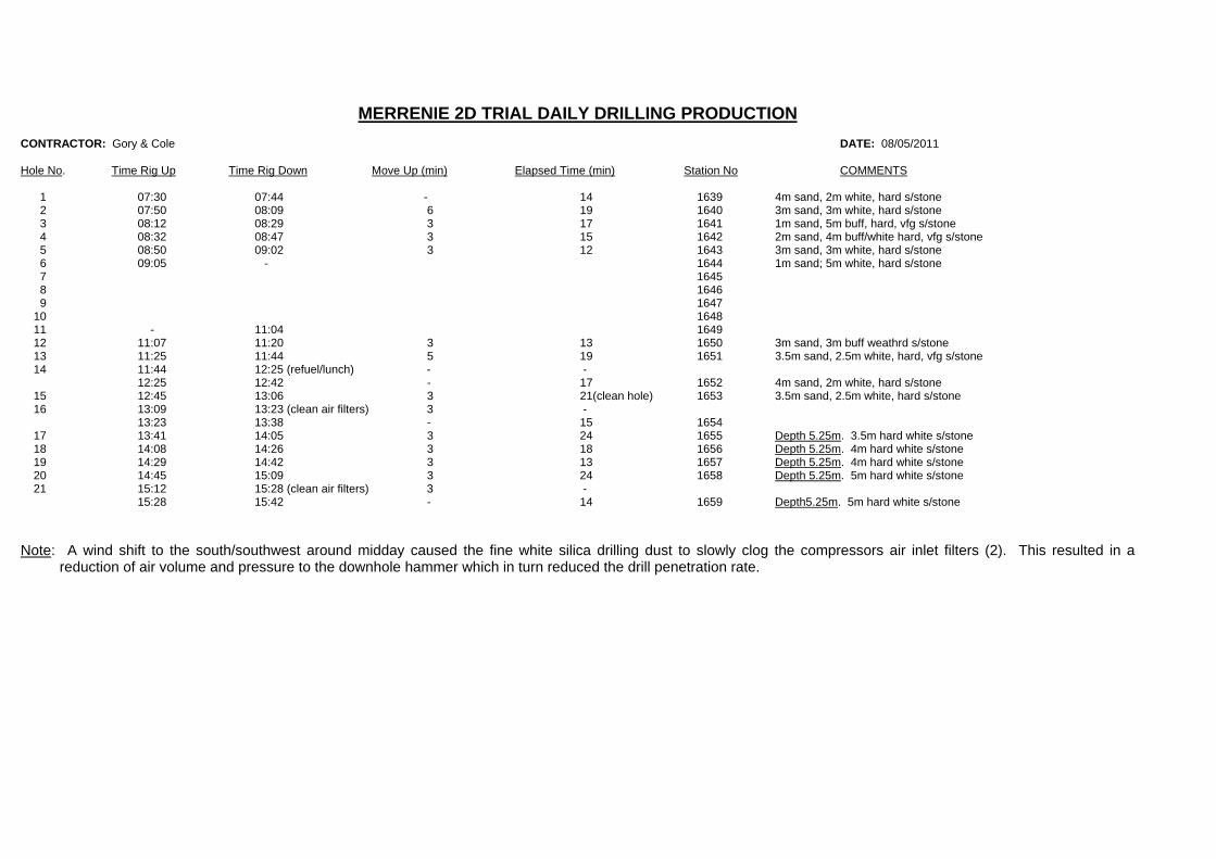
MERRENIE 2D TRIAL DAILY DRILLING PRODUCTION
CONTRACTOR: Gory & Cole DATE: 08/05/2011
Hole No. Time Rig Up Time Rig Down Move Up (min) Elapsed Time (min) Station No COMMENTS
1 07:30 07:44 - 14 1639 4m sand, 2m white, hard s/stone 2 07:50 08:09 6 19 1640 3m sand, 3m white, hard s/stone 3 08:12 08:29 3 17 1641 1m sand, 5m buff, hard, vfg s/stone 4 08:32 08:47 3 15 1642 2m sand, 4m buff/white hard, vfg s/stone 5 08:50 09:02 3 12 1643 3m sand, 3m white, hard s/stone 6 09:05 - 1644 1m sand; 5m white, hard s/stone 7 1645 8 1646 9 1647 10 1648 11 - 11:04 1649 12 11:07 11:20 3 13 1650 3m sand, 3m buff weathrd s/stone 13 11:25 11:44 5 19 1651 3.5m sand, 2.5m white, hard, vfg s/stone 14 11:44 12:25 (refuel/lunch) - - 12:25 12:42 - 17 1652 4m sand, 2m white, hard s/stone 15 12:45 13:06 3 21(clean hole) 1653 3.5m sand, 2.5m white, hard s/stone 16 13:09 13:23 (clean air filters) 3 - 13:23 13:38 - 15 1654 17 13:41 14:05 3 24 1655 Depth 5.25m. 3.5m hard white s/stone 18 14:08 14:26 3 18 1656 Depth 5.25m. 4m hard white s/stone 19 14:29 14:42 3 13 1657 Depth 5.25m. 4m hard white s/stone 20 14:45 15:09 3 24 1658 Depth 5.25m. 5m hard white s/stone 21 15:12 15:28 (clean air filters) 3 - 15:28 15:42 - 14 1659 Depth5.25m. 5m hard white s/stone Note: A wind shift to the south/southwest around midday caused the fine white silica drilling dust to slowly clog the compressors air inlet filters (2). This resulted in a
reduction of air volume and pressure to the downhole hammer which in turn reduced the drill penetration rate.

APPENDIX 6 - TAPE LIST
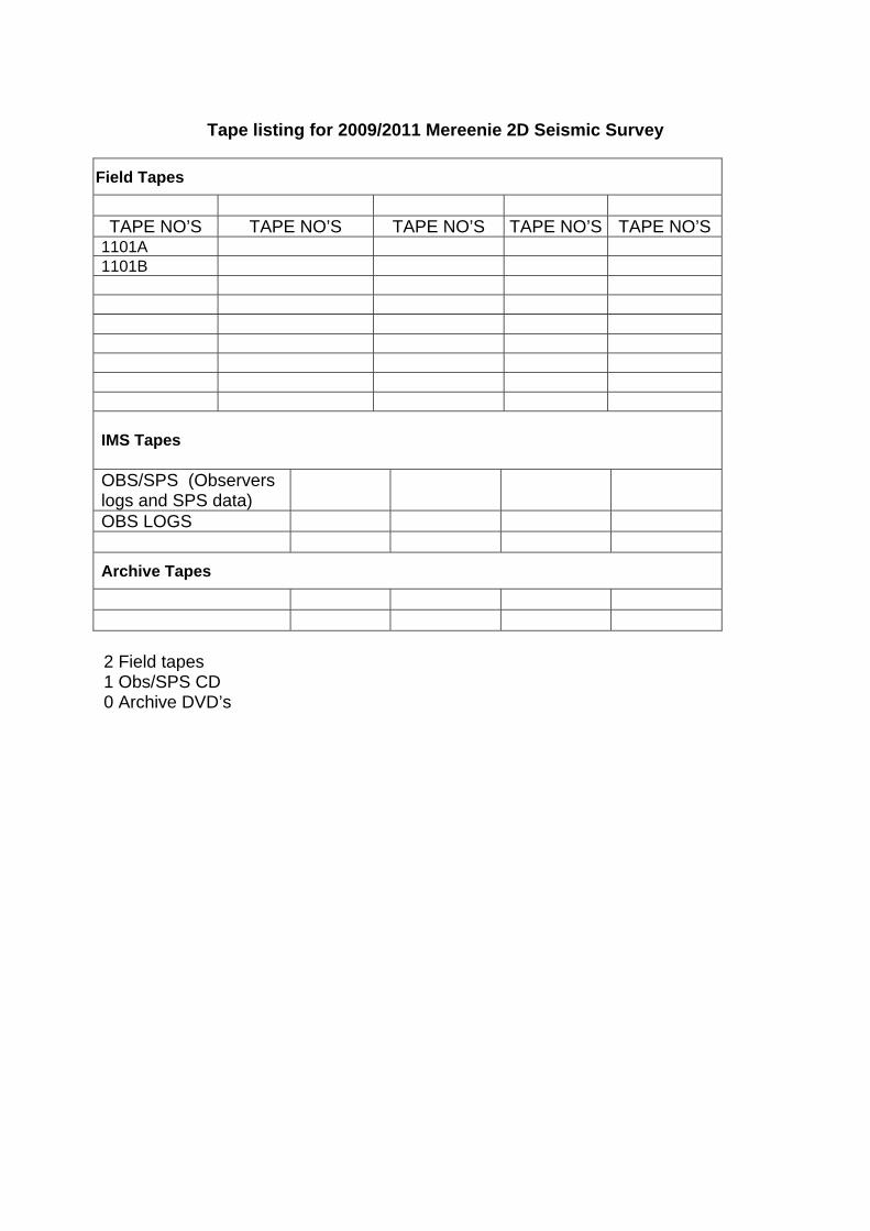
Tape listing for 2009/2011 Mereenie 2D Seismic Survey
Field Tapes
TAPE NO’S TAPE NO’S TAPE NO’S TAPE NO’S TAPE NO’S
1101A 1101B IMS Tapes OBS/SPS (Observers logs and SPS data)
OBS LOGS Archive Tapes 2 Field tapes 1 Obs/SPS CD 0 Archive DVD’s

APPENDIX 7 - MAPS

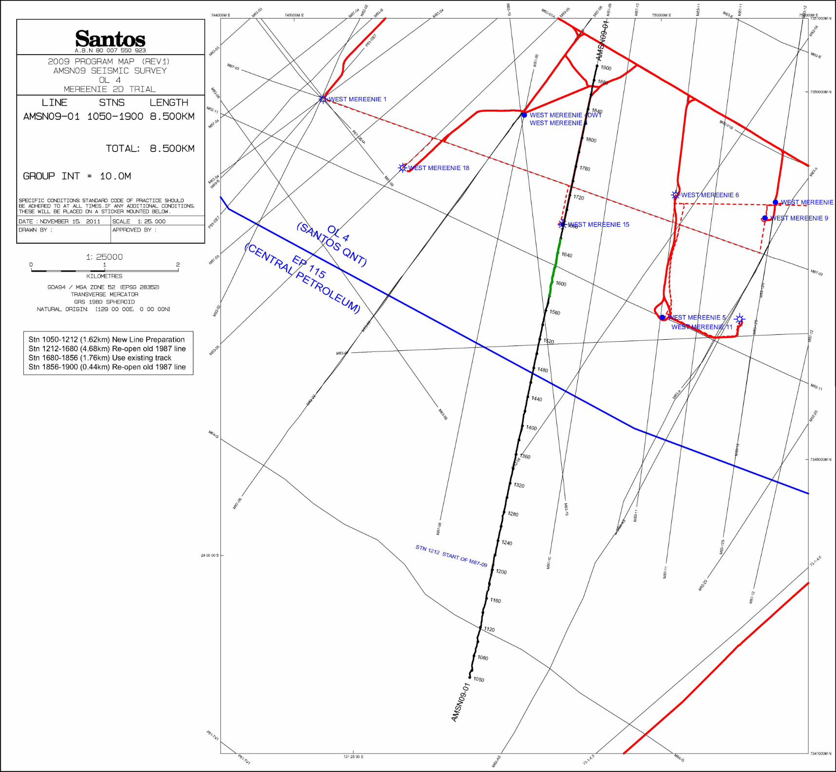


![WordPress.com · opues 'H ep o JlWlJdW! e (u) ep ep 0Jewr)u o 00!qo enb JOIeW eras eonr enb eded oe]es soue e w OL' L we) eonr 01uenbue 'oue Jod eosen e W09'L wel 001140](https://static.fdocuments.net/doc/165x107/60e6f84d32effa7bec3b9a85/opues-h-ep-o-jlwljdw-e-u-ep-ep-0jewru-o-00qo-enb-joiew-eras-eonr-enb-eded.jpg)