OPERATING INSTRUCTIONS Non-Electric Pressure Steam Sterilizers

AMSCO® EVOLUTION® LMEDIUM STEAM STERILIZERS
660 x 660 mm (26 x 26") SterilizerVertical Sliding Door
660 x 953 mm (26 x 37-1/2") SterilizerHorizontal Sliding Door
660 x 953 mm (26 x 37-1/2") SterilizerManual Hinged Door
Typical - details may vary.
APPLICATION
AMSCO® Evolution® L Medium Steam Sterilizers are a prevacuum series of sterilizer designed for use in laboratory and industrial applications.
Evolution L prevacuum sterilizers are equipped with prevacuum, gravity, liquid, leak test and daily air removal test cycles.
The sterilizers efficiently sterilize:
• porous, heat- and moisture-stable materials
• liquids & media (in borosilicate glass containers with vented closures)
• laboratory supplies
SD886 (11/01/15)
Item ________________________
Location(s)_______________________________________________
Door Configurations (660 x 953 mm Units)Horizontal Sliding Door– Only A and C applyHinged Door– A through F apply
HORIZONTAL SLIDING DOOR (660 X 593 MM)❑ LVS699-671 660 x 953 x 1067mm (26 x 37-1/2 x 42")
❑ LVS6912-864 660 x 953 x 1372mm (26 x 37-1/2 x 54")
❑ LVS6915-1053 660 x 953 x 1676mm (26 x 37-1/2 x 66")
❑ SINGLE DOOR - Horizontal Sliding❑ (A) Left-Hand
❑ Cabinet Enclosed/Freestanding❑ Recessed
❑ DOUBLE DOOR - Horizontal Sliding❑ (C) Left-Hand/Right Hand 1
❑ Recessed through One Wall❑ Recessed through Two Walls
HINGED DOOR (660 X 593 MM)❑ LVH699-671 660 x 953 x 1067mm (26 x 37-1/2 x 42")
❑ LVH6912-864 660 x 953 x 1372mm (26 x 37-1/2 x 54")
❑ LVH6915-1053 660 x 953 x 1676mm(26 x 37-1/2 x 66")
❑ SINGLE DOOR - Hinged❑ (A) Left-Hand ❑ (B) Right-Hand
❑ Cabinet Enclosed/Freestanding❑ Recessed
❑ DOUBLE DOOR - Hinged❑ (C) Left-Hand/Right-Hand 1
❑ (D) Left-Hand/Left-Hand 1
❑ (E) Right-Hand/Left-Hand 1
❑ (F) Right-Hand/Right-Hand 1
❑ Recessed through One Wall❑ Recessed through Two Walls
VERTICAL SLIDING DOOR (660 X 660 MM)❑ LV669-430 660 x 660 x 991mm (26 x 26 x 39")
❑ LV6612-540 660 x 660 x 1245mm (26 x 26 x 49")
❑ LV6615-675 660 x 660 x 1549mm (26 x 26 x 61")
❑ SINGLE DOOR - Vertical Sliding❑ Cabinet Enclosed/Freestanding❑ Recessed
❑ DOUBLE DOOR - Vertical Sliding❑ Recessed through One Wall❑ Recessed through Two Walls
STEAM SOURCE❑ Building Steam❑ Electric Steam Generator
❑ Carbon-Steel ❑ Stainless Steel
Voltage Options❑ 208 Volts ❑ 480 Volts❑ 240 Volts ❑ 600 Volts❑ 400 Volts
❑ Integral Indirect Stainless-Steel Clean Steam Generator (SD589)❑ Single Tube (for 26 x 26" units)❑ Double Tube (for 26 x 37.5" units)
STERILIZER ELECTRIC SERVICE❑ 208-240 VAC, 50/60 Hz, 3-Ph, 4 wire❑ 480 VAC, 50/60 Hz, 3-Ph with neutral, 5 wire❑ 400 VAC, 50 Hz, 3-Ph 5 wire Wye❑ 575/600 VAC, 60 Hz, 3-Ph 5 wire Wye
ACCESSORIES❑ Loading Car ❑ Transfer Carriage❑ Loading Car, Transfer Carriage, & Track Assembly
❑ Single Door ❑ Double Door❑ Stationary Docking Platform for Loading Car
❑ One (for Single Door)❑ Two (for Double Door)
❑ Chamber Rack and Shelf(LV669, LV699 and LV6912 Units, Only)
❑ Air Compressor, Portable, 115 Vac
OPTIONS❑ Liquid Air Cool Cycle❑ Effluent Decontamination Cycle2
❑ Clean Steam Piping❑ RTD Load Probe(s)
❑ One Probe ❑ Two Probes ❑ Bio-Seal (Double Door Units Only)2
❑ Sterile Side ❑ Non-Sterile Side❑ Air-Differential Seal (Double Door Units Only)
❑ Sterile Side ❑ Non-Sterile Side❑ Back Cabinet Panel❑ Air Detector System❑ Integral Green Tank System ❑ Closed Loop Chilled Water System (Vacuum & Drain)
❑ Printer on both ends❑ 0.2 Micron Bacterial Retentive Filter❑ Drain Line Reference Probe❑ Auto Flush for Steam Generator❑ Reference Recorder (3 Pen)❑ Chamber Penetrations for TRI-CLAMP®* Fittings3
❑ 1" (25 mm), Qty. 1 ❑ 3" (75 mm), Qty. 1❑ Seismic Tie-Down Kit4
❑ Backflow Preventer❑ Air-Tank Back-Up System (Special)❑ Right Hand Piping❑ Dry Contacts (Special)
Notes:1. Hinged and Horizontal Sliding Double-Door Units – Operating End (OE) door opening direction is listed first, Non-operating End (NOE) direction second. Directions are given in relation to facing OE and NOE, respectively. Refer to configuration figure.2. Units with decontamination and/or bio-seal options require UL/CSA field certification.3. Both 1" (25 mm) and 3" (75 mm) penetrations can be selected as part of the same order.4. Based on CA requirements.
OE OE
OE OE OE
A B C
D E F
NOE
OE
NOE NOE
NOE NOE NOE
Selections Checked Below Apply To This Equipment
*TRI-CLAMP® is a registered trademark of ALFA LAVAL INC.

.
Internal Dimensions DoorConfiguration
Cubic Inches
Cubic FeetModel Number Millimeters Inches Liters
LV669-430 660 x 660 x 991 mm 26 x 26 x 39" Vertical Slide 26, 364 15.2 430
LV6612-540 660 x 660 x 1245 mm 26 x 26 x 49" Vertical Slide 33, 124 19.1 540
LV6615-675 660 x 660 x 1549 mm 26 x 26 x 61" Vertical Slide 41, 236 23.8 675
LVH699-671 660 x 953 x 1067 mm 26 x 37-1/2 x 42" Hinged 40,950 23.7 671
LVH6912-864 660 x 953 x 1372 mm 26 x 37-1/2 x 54" Hinged 52, 650 30.5 864
LVH6915-1053 660 x 953 x 1676 mm 26 x 37-1/2 x 66" Hinged 64, 350 37.2 1053
LVS699-671 660 x 953 x 1067 mm 26 x 37-1/2 x 42" Horizontal Slide 40,950 23.7 671
LVS6912-864 660 x 953 x 1372 mm 26 x 37-1/2 x 54" Horizontal Slide 52, 650 30.5 864
LVS6915-1053 660 x 953 x 1676 mm 26 x 37-1/2 x 66" Horizontal Slide 64, 350 37.2 1053
DESCRIPTION
AMSCO Evolution L Steam Sterilizers are equipped with the latest features in both state-of-the-art technology and ease of use.
Primary Product Features –Interior Chamber Dimensions
• Horizontal-sliding Power Door or Easy-opening Hinged Door for 660 x 953 mm (26 x 37-1/2") or Vertical-slidingPower Door 660 x 660 mm (26 x 26") with quiet, motor-driven cable and pulley mechanism. Door movement is controlledfrom control panel push buttons.
» 660 x 660 mm (26 x 26") sterilizers – to open, power doortravels vertically down; and up to close.
» 660 x 953 mm (26 x 37-1/2") sterilizers – to open, the powerdoor travels horizontally right-to-left (on the operator end)and horizontally left-to-right at the non-operator end.
• 660 x 953 mm (26 x 37-1/2") sterilizers, also available withmanually-operated hinged door.
• All plumbing components are mounted to a free-standing,modular rack (skid). The skid connects to the core sterilizer assembly during installation.
Allen-Bradley MicroLogix™ Control System with enhanced functionality and user-friendly A-B PanelView Plus™ 600 interface screen.1
• Touch-sensitive screen with 18-bit color graphic display
• Display features 320 x 240 resolution color-active matrix
• Display uses easy to recognize symbols
• Operator panel includes compact Flash (CF-Card) memory card slot for memory backup/restore
• System includes help screens to aid in operation
• Includes service reprogrammable flash ROM memory
• Program is stored in flash memory for permanent storage
• Cycle parameters and calibrations are stored in flashmemory for permanent storage
STANDARDS
Each sterilizer meets applicable requirements of the following listings and standards, and carries the appropriate symbols:
• UL 61010-1
• EN 61010-1
• CSA C22.2, No. 61010-1 and 61010-2-040
• Pressure Equipment Directive (PED) 97/23/EC.
• ASME Code, Section VIII, Division 1 for unfired pressure vessels. The pressure vessel is so stamped; ASME FormU-1 is furnished. Shell and door are constructed to withstand working pressure of 3.1 bar (45 psig).
• EMC Directive: 2004/108/EC, 93/68/EEC, 92/31/EEC,89/336/EEC.
• Low Voltage Directive: 2006/95/EC, 93/68/EEC,72/23/EEC.
• Machinery Directive (MD): 2006/42/EC, 98/37/EEC,93/68/EEC, 91/368/EEC, 89/392/EEC.
FEATURES
660 x 953 mm (26 x 37-1/2") Chamber Cross-section or 660 x 660 mm (26 x 26") Chamber Cross-section sized to allow for efficient, high-volume processing of hard goods and liquid loads.
Vertical-sliding Power Doors and Horizontal-sliding Power Doors are controlled from control panel push buttons. Doors slide open, propelled by a cable and pulley driven by an electric motor. Double door configurations are supplied with controls at both ends of the sterilizer to help prevent the possibility of cross-contamination.
Fast-operating, Low-effort Manually-operated Door Lock Mechanism (hinged-door models) allows the door to be locked or unlocked, using a single 30° handle motion.1. Allen-Bradley MicroLogixTM and Allen-Bradley PanelView PlusTM
are trademarks of Rockwell Automation, Inc.
660 x 660 x 991 mm(26 x 26 x 39") – 430 L capacity
660 x 660 x 1245 mm(26 x 26 x 49") – 540 L capacity
660 x 660 x 1549 mm(26 x 26 x 61") – 675 L capacity
660 x 953 x 1067 mm (26 x 37-1/2 x 42") – 671 L capacity
660 x 953 x 1372 mm(26 x 37-1/2 x 54") – 864 L capacity
660 x 953 x 1676 mm(26 x 37-1/2 x 66") – 1053 L capacity
2

Software Calibration is performed in the Service Mode, accessible through the touch screen displays, and accomplished using external or internal temperature and pressure sources. Control system provides printed record of all calibration data for verification to current readings.
Rs-232 Interface Port is provided for downloading cycle information to Customer-furnished data acquisition system.
Pneumatic Valves are fitted in piping for steam, water and exhaust control.
Copper/brass Piping is used on all chamber steam supply piping and is joined by traditional plumbing fittings. Principle piping components and the primary control assembly are mounted to a separate, modular support rack (plumbing skid). The plumbing skid connects during installation to core chamber and frame assembly, allowing for increased access for service and maintenance procedures when necessary. Optional stainless-steel piping is available.
Visible Pressure Gauges show chamber and jacket pressure on control panel.
UTILITIES CONSERVATION FEATURES
Resistance Temperature Detectors (RTD) are installed for precise sterilizer temperature control and conservation of utilities. Dual element chamber drain line RTD senses and controls temperature variations within sterilizer chamber. Jacket RTD provides temperature control within jacket space. These RTD signals, converted into electrical impulses, provide accurate control inputs and readouts throughout entire cycle.
Electronic Water Saving Control includes an RTD to minimize the amount of water used in condensing the exhausted chamber steam and condensate.
Automatic Utilities Start-up/shutdown permits utilities conservation. Shutdown may be programmed to activate at the end of any designated cycle or time of day. When activated, the control system automatically shuts off all utility valves, conserving steam and water usage. Sterilizer utilities can be restarted either by programmed time or manual operation. A different shutdown and restart time can be programmed for each day.
Insulation, one-inch thick, asbestos-free spin-glass (rated at 500 °F [260 °C] continuous) encompasses the exterior of the sterilizer vessel and is sealed in an oil and water resistant outer jacket.
Two-stage Vacuum Pump is supplied on all units to effectively pull chamber to specified vacuum levels, reduce cycle time by shortening conditioning and exhaust times; as well as reduce water consumption
CYCLE DESCRIPTION
Twenty (20) cycles are available as a standard feature. Sterilizer is factory-programmed with the following applicable sterilizing cycles:
• Gravity Cycle, for the sterilization of heat- and moisture-stable goods at 100 to 141°C (212 to 285°F), anddecontamination of bagged non-biohazardous laboratorywastes. Gravity cycle utilizes the gravity air-displacementprinciple.
• Liquid Cycle, for the sterilization of liquids and media invented borosilicate glass or metal containers at 100 to 141°C (212 to 285°F). Liquid cycle utilizes the optimal solutioncooling feature, during exhaust (cooling) phase, to controlthe exhaust rate.
• Prevacuum Cycle for efficient, high-volume sterilization ofporous, heat- and moisture-stable materials at 100 to 141°C (212 to 285°F). Prevacuum cycle utilizes a mechanical air-evacuation system.
• Leak Test Cycle for verification of door seal and pipingsystem integrity. Cycle parameters are pre-programmedand fixed. The acceptable maximum leak rate is 1.0 mmHg/minute over a 10-minute period following a fixedstabilization time.
• Daily Air Removal Test (DART) Cycle for verification ofeffective removal of residual air in the chamber and loadduring testing. Test cycle determines if even and rapid steam penetration into test load has occurred. Cycle parametersare preprogrammed and fixed.
• Bowie-Dick Test is available for 121°C (250°F) prevacuum cycles.
Optional Cycles
• Liquid Air Cool Cycle provides water to the jacket, and airpressure to the chamber to improve exhaust time for liquidloads, and to reduce boil over.
• Effluent Decontamination Cycle is used for the processing of contaminated biohazardous laboratory waste (BL-3 andBL-4). The condensate produced during the processingcycle is decontaminated before discharge to the floor drain. The steam is admitted through the bottom of the sterilizerchamber, and the chamber is exhausted out the top side of the vessel. During the purge and vacuum pulses, all purgeand exhaust gases are vented through a 0.2 micron bacterial retentive filter. The filter housing is steam jacketed to prevent wetting of the filter membrane. Available with fast exhaustor optimal solution cooling (slow exhaust) exhaust types.User is responsible for development of process parameters. Control display screen provides number of hours of filter use.
Ready State Screen – Prevac Cycles
3

CONTROL SYSTEM
Design Features
The Allen-Bradley MicroLogixTM 1200 PLC1 monitors and controls all sterilizer operations. The control system is factory-programmed with standard sterilizing cycles. Each cycle is adjustable to meet specific processing requirements. All control configuring is performed through the touch screen displays.
Cycle values and operating features may be adjusted and verified prior to cycle operation. Once cycle is started, cycles and cycle values cannot be changed until cycle is complete. On completion of cycle, timers reset to the previously selected values, eliminating the need to reset values between repeated cycles. If chamber temperature drops below the under temperature setting during the exposure phase, the timer can be set to stop and automatically reset or resume once normal operating temperature is reached.
Critical control system components are housed within a sealed compartment to protect the components from moisture and heat generated during the sterilization process.
Operator Interface Control Panel, consisting of a touch screen and impact printer, is located on the operating (load or non-sterile) end of the sterilizer. If sterilizer is equipped with double doors, an additional touch screen is provided on the sterilizer non-operating (unload or sterile) end.
• Touch-Sensitive Screen features a color active matrix with 18-bit graphics display. All sterilizer functions, includingcycle initiation and cycle configuration, are operated bypressing the touch-sensitive areas on the display, referredto as buttons. Display indicates appropriate control buttons, operator prompts and status messages necessary to assist in sterilizer operation. All displayed messages are complete phrases with no codes to be cross-referenced. Display also indicates any abnormal conditions that may exist either inor out of a cycle.
• Ink-On-Paper Impact Printer, located below touch screen, provides an easy-to-read printed record of all pertinent cycledata on 2-1/4" wide paper, 40 column format. Data isautomatically printed at the beginning and end of each cycle and at transition points during the cycle. A duplicate printcan be obtained of the last cycle run.
Printer take-up spool stores an entire roll of paper, providing cycle records which can be saved for future reference. Three paper tape rolls are furnished with each unit.
Non-operating End (NOE) Control Panel (equipped on double-door sterilizers only) includes a touch-sensitive screen similar to the operating end screen. Preprogrammed cycles can be started from the NOE control panel. Display concurrently shows the same information as the operating end screen display.
Cycle Configuration is performed by accessing the change values menu through the operating end touch screen. In addition to adjustment of cycle values, the following operating parameters can also be changed through the change values menu:
• Time Display and Printout Units in standard AM/PM or24-hour military (MIL) time.
• Selectable Cycle Name permits user to name each cyclewith any combination of letters, numbers, blank spaces, and underscores, up to eight characters long.
• Print Interval permits adjustment of the time period between cycle-status printouts generated during the sterilize phase.
• Security Access Code is required to enter the operatingmode (running cycles), supervisor mode (changing values) and service mode. Operating the sterilizer or accessingchange values menu causes display to request the entry ofan access code. If access code is not properly entered,display returns to the standby screen, denying user access to the sterilizer or programming. Access to the sterilizer can be limited to 12 operators, each with a different access code.
• Buzzer pulses on and off during alarm conditions. Buzzerpulses at a different rate for one minute at cycle completion.
• Temperature Display and Printout Units in Celsius (°C) orFahrenheit (°F). Temperature is set, displayed, controlledand printed to the nearest 0.1°. Recalibration is not required when changing temperature units from °C to °F and viceversa.
• Pressure/Vacuum Display and Printout Units inpsig/In/Hg, Bar (Gauge). Recalibration is not required when changing pressure units.
• Compact Flash Port is provided for downloading cycleinformation to a Customer-furnished spreadsheet file.Approximately eight (one hour) cycles can be stored on theflash card before the card has to be downloaded to PC.
Flash Memory permanently backs up all cycle memory. If a power failure occurs during a cycle, proper cycle completion occurs once power is restored. When power is lost, the cycle is held in phase until power is restored, exceeding the minimum government specification of one minute. Once power returns, the event is recorded on the printout and the cycle automatically resumes or restarts, depending on what phase the cycle was in at the time of power loss. If necessary, the operator can manually abort the cycle.
SAFETY FEATURES
Emergency Stop Button for power door sterilizers is located on the front panel, below the sterilizer control touch pad. When pressed, immediately shuts off all outputs on the sterilizer. A key is used to reset the switch. This is an option for power-door equipped sterilizers only.
Control Lockout Switch equipped on chamber door(s), senses when door seal is energized and tight against the door. Control prevents cycle from starting until the limit switch signal is received. If control loses appropriate signal during cycle, alarm activates, cycle aborts and chamber safely vents with a controlled exhaust.Chamber Float Switch activates alarm, aborts cycle and safely vents chamber with a controlled exhaust if excessive condensate is detected in the vessel chamber.Pressure Relief Valve limits the amount of pressure buildup so that the rated pressure in the vessel is not exceeded.Power Door Safety Feature causes door drive to slip if the sliding door encounters an obstruction during its movement.
1. Allen-Bradley MicroLogixTM is a trademark of RockwellAutomation, Inc.
4
CONSTRUCTION
Shell Assembly
Two fabricated Type 316L stainless-steel shells, welded one within the other, form the sterilizer vessel. A stainless-steel end frame(s) is welded to door end. On single door units, back of chamber is fitted with welded, stainless-steel dished head.
Sterilizer vessel is ASME and PED rated at 3.1 bar (45 psig) and insulated. Vessel includes one 1"-NPT chamber port for Customer use.
Steam-supply opening inside the chamber is shielded by a stainless-steel baffle.
Chamber Door(s)
Door is constructed of 316L stainless steel.
During cycle operation, door is sealed by a steam-activated door seal. Door seal is constructed of a special long-life rubber compound. When sterilize cycle is complete, the seal retracts under vacuum into a machined groove in the sterilizer's end frame.
During the “complete” phase of the cycle and out of cycle, the door(s) are sealed using compressed air (double door only).
A proximity switch is used by the control to determine if door is closed. An additional seal pressure switch prevents inadvertent cycle initiation if door is not sealed.
The door assembly on hinged door units is equipped with a locking mechanism that ensures the door cannot be opened as long as the seal is intact and energized and more than 0.14 bar (2 psig) pressure is in the chamber.
The sterilizer door is fitted with a stainless-steel panel that insulates the operator from the chamber end frame, reducing the chance of accidental contact with a hot metal surface.
Door interlocks on double door sterilizers can be programmed to prevent inadvertent opening of door(s). Access code is required to override door interlocks.
Chamber Drain System
Drain system is designed to prevent pollutants from entering into the water-supply system and sterilizer.
The automatic condensing system, consisting of a heat exchanger, converts chamber steam to condensate and disposes condensate to waste. Cooling water flow is regulated by the waste line RTD to minimize water usage. Water supply shutoff valve is located in the recessed area of the unit.
Vacuum System
A two-stage vacuum pump reduces chamber pressure during prevacuum and post-drying phases. Air is drawn from the chamber through the vacuum system. Following the dry phase, chamber vacuum is relieved to atmospheric pressure by admitting air through a bacteria-retentive filter.
Steam Source
Sterilizers are piped, valved and provided with a trap to receive building-supplied steam delivered at 3.5 to 5.6 bar (50 to 80 psig) dynamic. Standard steam piping is constructed of copper-brass and stainless steel; and includes a shutoff valve, strainer and a pressure regulator. An optional, stand-alone electric steam generator is also available.
Steam feeds from the jacket to the chamber. A check valve is added between the jacket and chamber on sterilizers with decontamination cycle option.
Piping
All piping is located on a modular plumbing rack (skid). Plumbing skid can be located on either side of the sterilizer.
MOUNTING ARRANGEMENT
Sterilizers are arranged for either freestanding or recessed installation, as specified. Each sterilizer is height-adjustable. Sterilizer subframe is equipped with a synthetic rubber gasket to ensure tight fit between the panels on freestanding units or between the front cabinet panel and wall partition on recessed units.
On freestanding units, stainless-steel side panels and a louvered top panel enclose the sterilizer body and piping.
ACCESSORIES
Material Handling Accessories include stainless-steel chamber tracks and stainless-steel loading cars with painted-steel carriages. Stainless-steel chamber rack and shelf are available for model LV669, LV699 and LV6912 sterilizers, only. See separate product literature for details.
Air Compressor, Portable, 115 Vac. This accessory is intended for pneumatic valves on sterilizers when an air utility is not provided by the facility. It may also be used for back-up pressure source for the door seal in bioseal applications.
This is a portable 1.5 Gallon compressor tank that delivers 59.5 LPM @ 345 KPa (1.7 CFM @ 100 PSI). Refer to STERIS drawing no. 755718-038 for complete specifications.
OPTIONS
Clean Steam Piping delivers steam generated from Customer purified water source to the chamber and its contents. All steam-to-chamber piping components are stainless steel, sanitary type fittings.
Integral Indirect Stainless-steel Clean Steam Generator automatically produces clean steam using Customer-supplied steam and purified water. Generator is integrally connected to the clean steam-to-chamber piping system. Steam pressure at the sterilizer must be 75 psig minimum. Available with single or double tube sheet constructions. See tech data SD589 for details.
Integral 45 Kw Carbon-steel Electric Steam Generator is typically fed by a potable water source with hardness not to exceed 171 mg/L. The generator is available for both single and double door sterilizers.
Auto Flush For Integrally Mounted Steam Generator provides automatic flush of steam generator upon start upof sterilizer. (Not required for SS generators.)
NOTE: Additional width is required if generator is selected.
Integral 45 Kw Electric Stainless-steel Steam Generator is electrically powered, automatically filled with water and operates whenever the sterilizer power is on. Generator is integrally connected to the clean steam-to-chamber piping system.
NOTE: Additional width is required if generator is selected.
RTD Load Probes And F0 Sterilization automatically sense load temperature during cycle operation. A single thermal load probe is sealed through the sterilizer vessel and manually placed in the product container, or in a load simulator within the chamber prior to cycle operation.
5

In conjunction with the load probe option, individual cycles can be set to start exposure phase according to chamber drain temperature or according to load temperature. Also, F0 set points are available for each cycle, allowing for exposure phase termination based on the calculated F0 value. Note that a maximum of two probes can be provided.
Bio-seal (double door units only) is a 1/4" stainless-steel plate welded to the chamber and a 1/4" thick silicone gasket that extends between the plate and a carbon steel wall frame which is welded to wall imbeds. The bioseal, provided on the operating and/or non-operating end of the sterilizer, prevents passage of airborne microorganisms from the space between the vessel body and the structural wall opening. Steam is the primary source of pressure behind the door seal. All sterilizers with bioseals have air back-up to maintain seal pressure when out of cycle or if the steam source is not available.
Air-differential seal (double door units only), provided on the non-operating end of the sterilizer, minimizes airflow between the dirty and clean sides of the barrier.
0.2 Micron Bacterial Retentive Filter provides sterile air during airbreak at end of cycle.
Back Cabinet Panel is provided on single door, freestanding units where the unit is accessible on all sides.
Air Detector System (integral factory piping option) is used to determine whether any air or non-condensible gas present in the chamber is sufficient to impair the sterilizing process.
Seismic Tie-down Kit conforms to Title 24 of 2007 California Building Code.
Backflow Preventer option can be installed on sterilizer piping to prevent the unwanted reverse flow of water or other substances into the potable water supply.
Air-tank Back-up System has been designed specifically for high level containment steam sterilizer applications which require that chamber doors remain sealed even when utilities are lost.
The integrity of the seals are tested prior to initiation of the cycle. A compressed air tank provides air pressure to door seals for at least 8 hours if normal steam pressure falls below minimum supply pressure of 3.1 bar (45 psig). Should steam or electrical power be lost, cycle aborts and chamber exhausts safely to atmospheric pressure. On loss of compressed air, chamber remains sealed and air tank provides backup pressure. Cycle aborts on return of compressed air through the normal supply line or through a supplemental service connection.
A detailed failure modes and effect analysis has been conducted for the air tank back up system.
This option is available through Special Sales Quote (SSQ) only.
Right Hand Piping. Piping skid is located on right side of sterilizer. Added length flexible hoses complete the connection.
Dry Contacts control relays when sterilizer is On/Off and door is Open/Closed or an alarm is occurring. This option is available through SSQ only.
Additional 1" (25 mm) Chamber Penetration for TRI-CLAMP®1 Fitting – One capped chamber penetration port, for TRI-CLAMP fitting, is located at the side of the vessel so as not interfere with other piping.
3" (76 mm) Chamber Penetration for TRI-CLAMP Fitting – permits insertion of temperature probes, such as thermocouples or resistance temperature detectors (RTDs),
into the chamber. The assembly includes a stainless-steel threaded clamp, seal and seat to accept a maximum of 12 Customer-supplied probes.
Closed Loop Chilled Water System (vacuum & drain). Closed loop cooling source is used to cool the vacuum pump seal water to <15°C (<59°F ) and sterilizer effluent to <60°C (<140°F). This greatly reduces the amount of vacuum pump seal water and eliminates the need for water mixing with the effluent that is sent to drain. Plate heat exchangers and recirculation tank are included. See equipment drawings for closed loop utility requirements.
Integral Green Tank System. Domestic water is recirculated and refreshed only when the vacuum pump seal water and drain temperature reach required levels. A small water recirculation tank is used to supply most of the vacuum pump seal and effluent cooling water during the cycle and the control system monitors and determines when to add fresh water. This option can save a significant amount of domestic water compared to the standard system. A separate chilled water supply is not required with this option.
Reference Recorder: An optional independent recorder is provided to record chamber drainline temperature and chamber pressure. The recorder is integrally mounted to the sterilizer fascia paneling.
Printer on Both Ends. An additional printer is provided on the non-operating end of the sterilizer.
Drain Line Reference Probe automatically senses the drain line temperature during cycle operation. Individual cycles can be set to start the exposure phase according to chamber drain temperature, or according to load temperature.
PREVENTIVE MAINTENANCE
A global network of skilled service specialists can provide periodic inspections and adjustments to help assure low-cost peak performance. STERIS representatives can provide information regarding annual maintenance agreements.
NOTES
1. Customer is responsible for backflow protection, if required.
2. Pipe sizes shown indicate terminal outlets only. Building service lines, provided by others, must supply the specified pressures and flow rates.
3. Disconnect switches (with OFF position lockout only; switches not supplied by STERIS) should be installed in electric supply lines near the equipment.
4. Access to the recessing area from the control end of the sterilizer is recommended.
5. Clearances shown are minimal for installing and servicing the equipment.
6. Depending on the loading equipment used, additional clearance is required:
• If shelves are used, length of sterilizer plus 610 mm (24") at each door (1067 mm [42"] and 991 mm [39"] sterilizers, only).
• If loading car and carriage will be used. See appropriate equipment drawing for proper loading car clearance.
7. Floor drain should be provided within confines of sterilizer framework.
6
CUSTOMER IS RESPONSIBLE FOR COMPLIANCE WITH APPLICABLE LOCAL AND NATIONAL CODES AND REGULATIONS.
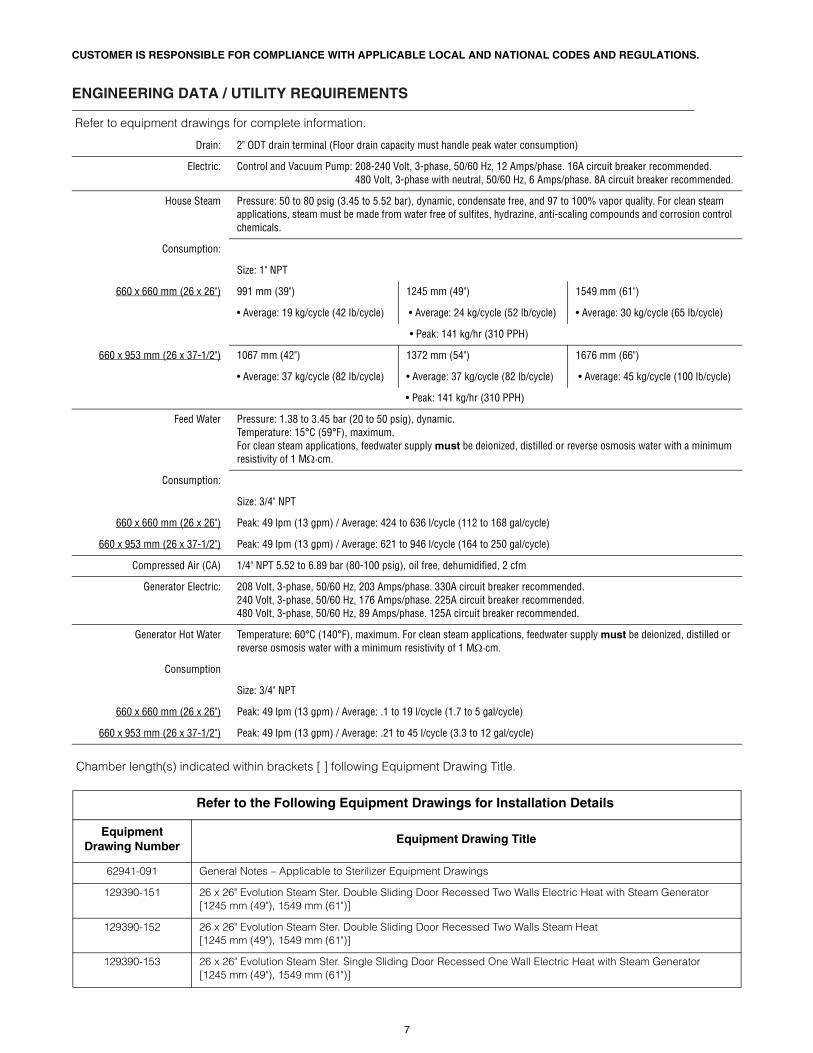
Chamber length(s) indicated within brackets [ ] following Equipment Drawing Title.
ENGINEERING DATA / UTILITY REQUIREMENTS
Refer to equipment drawings for complete information.
Drain: 2" ODT drain terminal (Floor drain capacity must handle peak water consumption)
Electric: Control and Vacuum Pump: 208-240 Volt, 3-phase, 50/60 Hz, 12 Amps/phase. 16A circuit breaker recommended.480 Volt, 3-phase with neutral, 50/60 Hz, 6 Amps/phase. 8A circuit breaker recommended.
House Steam Pressure: 50 to 80 psig (3.45 to 5.52 bar), dynamic, condensate free, and 97 to 100% vapor quality. For clean steam applications, steam must be made from water free of sulfites, hydrazine, anti-scaling compounds and corrosion control chemicals.
Consumption:
Size: 1" NPT
660 x 660 mm (26 x 26") 991 mm (39") 1245 mm (49") 1549 mm (61")
• Average: 19 kg/cycle (42 lb/cycle) • Average: 24 kg/cycle (52 lb/cycle) • Average: 30 kg/cycle (65 lb/cycle)
• Peak: 141 kg/hr (310 PPH)
660 x 953 mm (26 x 37-1/2") 1067 mm (42") 1372 mm (54") 1676 mm (66")
• Average: 37 kg/cycle (82 lb/cycle) • Average: 37 kg/cycle (82 lb/cycle) • Average: 45 kg/cycle (100 lb/cycle)
• Peak: 141 kg/hr (310 PPH)
Feed Water Pressure: 1.38 to 3.45 bar (20 to 50 psig), dynamic.Temperature: 15°C (59°F), maximum. For clean steam applications, feedwater supply must be deionized, distilled or reverse osmosis water with a minimum resistivity of 1 M·cm.
Consumption:
Size: 3/4" NPT
660 x 660 mm (26 x 26") Peak: 49 lpm (13 gpm) / Average: 424 to 636 l/cycle (112 to 168 gal/cycle)
660 x 953 mm (26 x 37-1/2") Peak: 49 lpm (13 gpm) / Average: 621 to 946 l/cycle (164 to 250 gal/cycle)
Compressed Air (CA) 1/4" NPT 5.52 to 6.89 bar (80-100 psig), oil free, dehumidified, 2 cfm
Generator Electric: 208 Volt, 3-phase, 50/60 Hz, 203 Amps/phase. 330A circuit breaker recommended.240 Volt, 3-phase, 50/60 Hz, 176 Amps/phase. 225A circuit breaker recommended.480 Volt, 3-phase, 50/60 Hz, 89 Amps/phase. 125A circuit breaker recommended.
Generator Hot Water Temperature: 60°C (140°F), maximum. For clean steam applications, feedwater supply must be deionized, distilled or reverse osmosis water with a minimum resistivity of 1 M·cm.
Consumption
Size: 3/4" NPT
660 x 660 mm (26 x 26") Peak: 49 lpm (13 gpm) / Average: .1 to 19 l/cycle (1.7 to 5 gal/cycle)
660 x 953 mm (26 x 37-1/2") Peak: 49 lpm (13 gpm) / Average: .21 to 45 l/cycle (3.3 to 12 gal/cycle)
Refer to the Following Equipment Drawings for Installation Details
Equipment Drawing Number
Equipment Drawing Title
62941-091 General Notes – Applicable to Sterilizer Equipment Drawings
129390-151 26 x 26" Evolution Steam Ster. Double Sliding Door Recessed Two Walls Electric Heat with Steam Generator [1245 mm (49"), 1549 mm (61")]
129390-152 26 x 26" Evolution Steam Ster. Double Sliding Door Recessed Two Walls Steam Heat [1245 mm (49"), 1549 mm (61")]
129390-153 26 x 26" Evolution Steam Ster. Single Sliding Door Recessed One Wall Electric Heat with Steam Generator [1245 mm (49"), 1549 mm (61")]
7

129390-154 26 x 26" Evolution Steam Ster. Single Sliding Door Recessed One Wall Steam Heat [1245 mm (49"), 1549 mm (61")]
129390-155 26 x 26" Evolution Steam Ster. Single Sliding Door Cabinet Steam Heat [1245 mm (49"), 1549 mm (61")]
129390-156 26 x 26" Evolution Steam Ster. Single Sliding Door Cabinet Electric Heat with Steam Generator [1245 mm (49"), 1549 mm (61")]
129390-157 26 x 26" Evolution Steam Ster. Double Sliding Door Recessed One Wall Steam Heat [1245 mm (49"), 1549 mm (61")]
129390-158 26 x 26" Evolution Steam Ster. Double Sliding Door Recessed One Wall Electric Heat with Steam Generator[1245 mm (49"), 1549 mm (61")]
129390-168 26 x 26" Evolution Steam Ster. Double Sliding Door Recessed Two Walls Electric Heat with Steam Generator[991 mm (39")]
129390-169 26 x 26" Evolution Steam Ster. Double Sliding Door Recessed Two Walls Steam Heat [991 mm (39")]
129390-170 26 x 26" Evolution Steam Ster. Double Sliding Door Recessed One Wall Steam Heat [991 mm (39")]
129390-171 26 x 26" Evolution Steam Ster. Double Sliding Door Recessed One Wall Electric Heat with Steam Generator[991 mm (39")]
129390-159 26 x 37-1/2" Evolution Steam Ster. Double Sliding Door Recessed Two Walls Electric Heat with Steam Generator [1372 mm (54"), 1676 mm (66")]
129390-160 26 x 37-1/2" Evolution Steam Ster. Double Sliding Door Recessed Two Walls Steam Heat [1372 mm (54"), 1676 mm (66")]
129390-161 26 x 37-1/2" Evolution Steam Ster. Single Sliding Door Recessed One Wall Electric Heat with Steam Generator [1372 mm (54"), 1676 mm (66")]
129390-162 26 x 37-1/2" Evolution Steam Ster. Single Sliding Door Recessed One Wall Steam Heat [1372 mm (54"), 1676 mm (66")]
129390-163 26 x 37-1/2" Evolution Steam Ster. Single Sliding Door Cabinet Steam Heat[1372 mm (54"), 1676 mm (66")]
129390-164 26 x 37-1/2" Evolution Steam Ster. Single Sliding Door Cabinet Electric Heat with Steam Generator [1372 mm (54"), 1676 mm (66")]
129390-165 26 x 37-1/2" Evolution Steam Ster. Double Sliding Door Recessed One Wall Steam Heat [1372 mm (54"), 1676 mm (66")]
129390-166 26 x 37-1/2" Evolution Steam Ster. Double Sliding Door Recessed One Wall Electric Heat with Steam Generator [1372 mm (54"), 1676 mm (66")]
129390-172 26 x 37-1/2" Evolution Steam Ster. Double Sliding Door Recessed Two Walls Electric Heat with Steam Generator [1067 mm (42")]
129390-173 26 x 37-1/2" Evolution Steam Ster. Double Sliding Door Recessed Two Walls Steam Heat [1067 mm (42")]
129390-174 26 x 37-1/2" Evolution Steam Ster. Double Sliding Door Recessed One Wall Steam Heat [1067 mm (42")]
129390-175 26 x 37-1/2" Evolution Steam Ster. Double Sliding Door Recessed One Wall Electric Heat with Steam Generator [1067 mm (42")]
129390-213 26 x 37-1/2" Evolution Steam Ster. Single Sliding Door Recessed One Wall Electric Heat with Steam Generator [1067 mm (42")]
129390-214 26 x 37-1/2" Evolution Steam Ster. Single Sliding Door Recessed One Wall Steam Heat [1067 mm (42")]
129390-215 26 x 37-1/2" Evolution Steam Ster. Single Sliding Door Cabinet Steam Heat [1067 mm (42")]
129390-216 26 x 37-1/2" Evolution Steam Ster. Single Sliding Door Cabinet Electric Heat with Steam Generator [1067 mm (42")]
129390-217 26 x 26" Evolution Steam Ster. Single Sliding Door Recessed One Wall Electric Heat with Steam Generator [991 mm (39")]
129390-218 26 x 26" Evolution Steam Ster. Single Sliding Door Recessed One Wall Steam Heat [991 mm (39")]
Refer to the Following Equipment Drawings for Installation Details (Continued)
Equipment Drawing Number
Equipment Drawing Title
8

129390-219 26 x 26" Evolution Steam Ster. Single Sliding Door Cabinet Steam Heat [991 mm (39")]
129390-220 26 x 26" Evolution Steam Ster. Single Sliding Door Cabinet Electric Heat with Steam Generator [991 mm (39")]
129390-201 26 x 37-1/2" Evolution Steam Ster. Single (Hinge) Door Recessed One Wall Electric Heat with Steam Generator [1372 mm (54"), 1676 mm (66")]
129390-202 26 x 37-1/2" Evolution Steam Ster. Single (Hinge) Door Recessed One Wall Steam Heat [1372 mm (54"), 1676 mm (66")]
129390-203 26 x 37-1/2" Evolution Steam Ster. Single (Hinge) Door Cabinet Electric Heat with Steam Generator [1372 mm (54"), 1676 mm (66")]
129390-204 26 x 37-1/2" Evolution Steam Ster. Single (Hinge) Door Cabinet Steam Heat [1372 mm (54"), 1676 mm (66")]
129390-205 26 x 37-1/2" Evolution Steam Ster. Single (Hinge) Door Recessed Two Walls Electric Heat with Steam Generator [1372 mm (54"), 1676 mm (66")]
129390-206 26 x 37-1/2" Evolution Steam Ster. Double (Hinge) Door Cabinet Steam Heat [1372 mm (54"), 1676 mm (66")]
129390-207 26 x 37-1/2" Evolution Steam Ster. Double (Hinge) Door Recessed One Wall Electric Heat with Steam Generator [1372 mm (54"), 1676 mm (66")]
129290-208 26 x 37-1/2" Evolution Steam Ster. Double (Hinge) Door Recessed One Wall Steam Heat [1372 mm (54"), 1676 mm (66")]
129390-209 26 x 37-1/2" Evolution Steam Ster. Double (Hinge) Door Recessed Two Walls Electric Heat with Steam Generator [1067 mm (42")]
129390-210 26 x 37-1/2" Evolution Steam Ster. Double (Hinge) Door Recessed Two Walls Steam Heat[1067 mm (42")]
129390-211 26 x 37-1/2" Evolution Steam Ster. Double (Hinge) Door Recessed One Wall Electric Heat with Steam Generator [1067 mm (42")]
129390-212 26 x 37-1/2" Evolution Steam Ster. Double (Hinge) Door Recessed One Wall Steam Heat [1067 mm (42")]
129390-221 26 x 37-1/2" Evolution Steam Ster. Single (Hinge) Door Recessed One Wall Electric Heat with Steam Generator [1067 mm (42")]
129390-222 26 x 37-1/2" Evolution Steam Ster. Single (Hinge) Door Recessed One Wall Steam Heat [1067 mm (42")]
129390-223 26 x 37-1/2" Evolution Steam Ster. Single (Hinge) Door Cabinet Electric Heat with Steam Generator [1067 mm (42")]
129390-224 26 x 37-1/2" Evolution Steam Ster. Single (Hinge) Door Cabinet Steam Heat [1067 mm (42")]
Refer to the Following Equipment Drawings for Installation Details (Continued)
Equipment Drawing Number
Equipment Drawing Title
9

660 x 660 mm (26 x 26") Sterilizer Service Clearance Values
Chamber Length
SService Clearance
LLoading Car Clearance
WWall Thickness
991 mm (39") 1168 mm (46") 2362 mm (93") 102 mm (4") Max.
1245 mm (49") 1422 mm (56") 2616 mm (103") 102 - 203 mm (4 - 8")
1549 mm (61") 1727 mm (68") 2946 mm (116") 102 - 203 mm (4 - 8")
*Stainless Steel Units Only: Add 153 mm (6" ) to service clearance. This note applicable to free-standing, cabinet enclosed and recessed, one wall units only.
Service Clearances
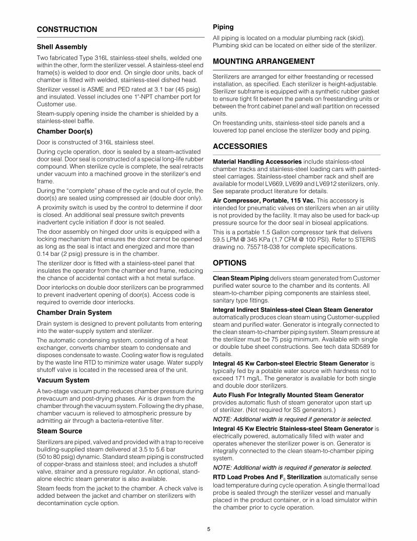
Recessed, Two Walls – 660 x 660 x 991 mm (26 x 26 x 39") Double Sliding-Door ConfigurationElectric Heat with Steam Generator
Drawing not to scale.Dimensions are typical.
Dimensions are mm and [in].
TypicalWall
Opening
1651 [65]
GeneratorService
Clearance
1270 ± 6[50 ± 1/4]
Plan View
Not For In
stallationL
699[27-1/2]
PlumbingService
Clearance
1194 [47]
Sterilizer
798[31-3/8]
ApproximateDrain
Location
95[3-3/4]
S
W
NOTE: Loading car docking station is located and anchored on floor in front of sterilizer.
10

660 x 953 mm (26 x 37.5") Sterilizer Service Clearance Values
Chamber Length
SService Clearance
LLoading Car Clearance
WWall Thickness
1067 mm (42") 1353 mm (53-1/4") 2515 mm (99") 102 mm (4") Max.
1372 mm (54") 1657 mm (65-1/4") 2845 mm (112") 102 - 203 mm (4 - 8")
1676 mm (66") 1962 mm (77-1/4") 3124 mm (123") 102 - 203 mm (4 - 8")
*Stainless Steel Units Only: Add 153 mm (6" ) to service clearance. This note applicable to free-standing, cabinet enclosed and recessed, one wall units only.
Recessed, Two Walls – 660 x 953 x 1372 mm (26 x 37.5 x 54") Double Sliding-Door ConfigurationElectric Heat with Steam Generator
Drawing not to scale.Dimensions are typical.
Dimensions are mm and [in].
Service Clearances
SPlan View
L
W 856[33-3/4]
GeneratorService
Clearance
1651 [65]
206[8-1/8]
TypicalWall
Opening
1803 ± 6[71 ± 1/4]
Not For In
stallation
1321 [52]
708[27-7/8]
PlumbingService
Clearance
Sterilizer
ApproximateDrain
Location
NOTE: Loading car docking station is located and anchored on floor in front of sterilizer.
11

For Further Information, contact:
This document is intended for the exclusive use of STERIS Customers, including architects or designers. Reproduction in whole or in part by any party other than a Customer is prohibited.SD886 ©2015, STERIS Corporation. All rights reserved. (11/01/15)
STERIS Corporation5960 Heisley RoadMentor, OH 44060-1834 • USA440-354-2600 • 800-548-4873www.STERISLifeSciences.com