AMPS Atlanta 2006-2007 Club Projectampscv.org/newsletters/AMPS-CV-M8-Group-Build-Suspension.pdf ·...
8
AMPS Central Virginia 2011-2012 Club Project Tamiya M-8 Armored Car The Schedule: 27 October – Steps 1-4, Lower hull and suspension 17 November – Steps 5-8, Lower hull detailing, basic upper hull construction and wheels 26 January – Steps 9-11, Upper hull detailing 23 February – Steps 12-15, Turret construction and detailing 22 March – Project wrap-up References: American Armored Fighting Vehicles - World War Two AFV Plans, George Bradford A Photo History of Armoured Cars in Two World Wars, George Forty Armored Car- A History of American Wheeled Combat Vehicles, R.J. Hunnicutt Captured Armored Cars and Other Vehicles in Wehrmacht Service in World War 2, Werner Regenberg Encyclopedia of Armoured Cars, Duncan Crow and Robert Icks Light Armoured Car M8 & Armoured Utility Car M20 (#MV-08: Military Vehicle Workshop Series), Allied Command Productions Mexican and Central American Armor, Darlington Productions, Julio Montes "M8 Greyhound" (October 2008 Issue of Military Machines International Magazine), John Blackman M8 Greyhound Armored Car (1941-1991), Osprey Publications, Steven Zaloga M8 Greyhound /M20 Utility Vehicle Technical Manual (TM 9-743), CD-ROM Easy 1 U.S. Armoured Cars - AFV Weapons Profile #40, Robert J. Icks U.S. Armored Cars in Action, Squadron Signal Productions, Jim Mesko, Allied-Axis The photo Journal of the Second World War, Issue 5, Ampersand Publishing, Pat Stansell War Wheels, http://www.warwheels.net/m8greyhoundINDEX.html , Patrick Keenan Toadman’s Tank Pictures, http://www.toadmanstankpictures.com/m8.htm, Chris “Toadman” Hughes 27 October 2011 General – Before we start, each of you will need to make a decision on how much detail you want to add to your M8. For example, if you’re going to add an engine compartment you’ll need to do so during Step 1 as you’ll need to remove part of the lower hull tub (part C16) and floor plate (part D32). You’ll need to consult the directions for your aftermarket engine compartment to determine just what and how much to remove. Likewise, if you’re going to build your M8 with the fenders removed, then you’ll need to add some additional details to the lower hull and suspension. Steps 1-3 are the best place to add this detail as lower hull and suspension parts are exposed and allow easy access. I plan to leave the fenders off my M8, so I’ll include the details in this description of the project build. Additionally, there are a lot of seam lines to clear-up in Steps 1-4. This is more
Transcript of AMPS Atlanta 2006-2007 Club Projectampscv.org/newsletters/AMPS-CV-M8-Group-Build-Suspension.pdf ·...

AMPS Central Virginia 2011-2012 Club Project Tamiya M-8 Armored Car
The Schedule: 27 October – Steps 1-4, Lower hull and suspension 17 November – Steps 5-8, Lower hull detailing, basic upper hull construction and wheels 26 January – Steps 9-11, Upper hull detailing 23 February – Steps 12-15, Turret construction and detailing 22 March – Project wrap-up References: American Armored Fighting Vehicles - World War Two AFV Plans, George Bradford A Photo History of Armoured Cars in Two World Wars, George Forty Armored Car- A History of American Wheeled Combat Vehicles, R.J. Hunnicutt Captured Armored Cars and Other Vehicles in Wehrmacht Service in World War 2, Werner Regenberg Encyclopedia of Armoured Cars, Duncan Crow and Robert Icks Light Armoured Car M8 & Armoured Utility Car M20 (#MV-08: Military Vehicle Workshop Series), Allied Command Productions Mexican and Central American Armor, Darlington Productions, Julio Montes "M8 Greyhound" (October 2008 Issue of Military Machines International Magazine), John Blackman M8 Greyhound Armored Car (1941-1991), Osprey Publications, Steven Zaloga M8 Greyhound /M20 Utility Vehicle Technical Manual (TM 9-743), CD-ROM Easy 1 U.S. Armoured Cars - AFV Weapons Profile #40, Robert J. Icks U.S. Armored Cars in Action, Squadron Signal Productions, Jim Mesko, Allied-Axis The photo Journal of the Second World War, Issue 5, Ampersand Publishing, Pat Stansell War Wheels, http://www.warwheels.net/m8greyhoundINDEX.html, Patrick Keenan Toadman’s Tank Pictures, http://www.toadmanstankpictures.com/m8.htm, Chris “Toadman” Hughes 27 October 2011 General – Before we start, each of you will need to make a decision on how much detail you want to add to your M8. For example, if you’re going to add an engine compartment you’ll need to do so during Step 1 as you’ll need to remove part of the lower hull tub (part C16) and floor plate (part D32). You’ll need to consult the directions for your aftermarket engine compartment to determine just what and how much to remove. Likewise, if you’re going to build your M8 with the fenders removed, then you’ll need to add some additional details to the lower hull and suspension. Steps 1-3 are the best place to add this detail as lower hull and suspension parts are exposed and allow easy access. I plan to leave the fenders off my M8, so I’ll include the details in this description of the project build. Additionally, there are a lot of seam lines to clear-up in Steps 1-4. This is more
2
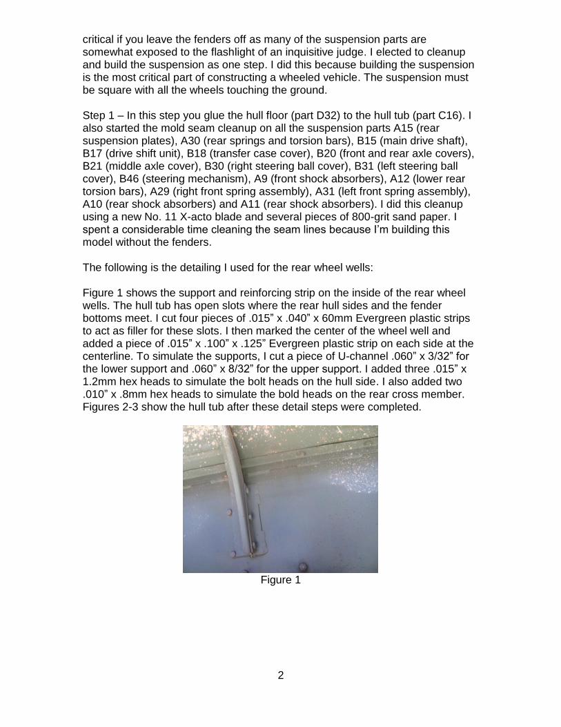
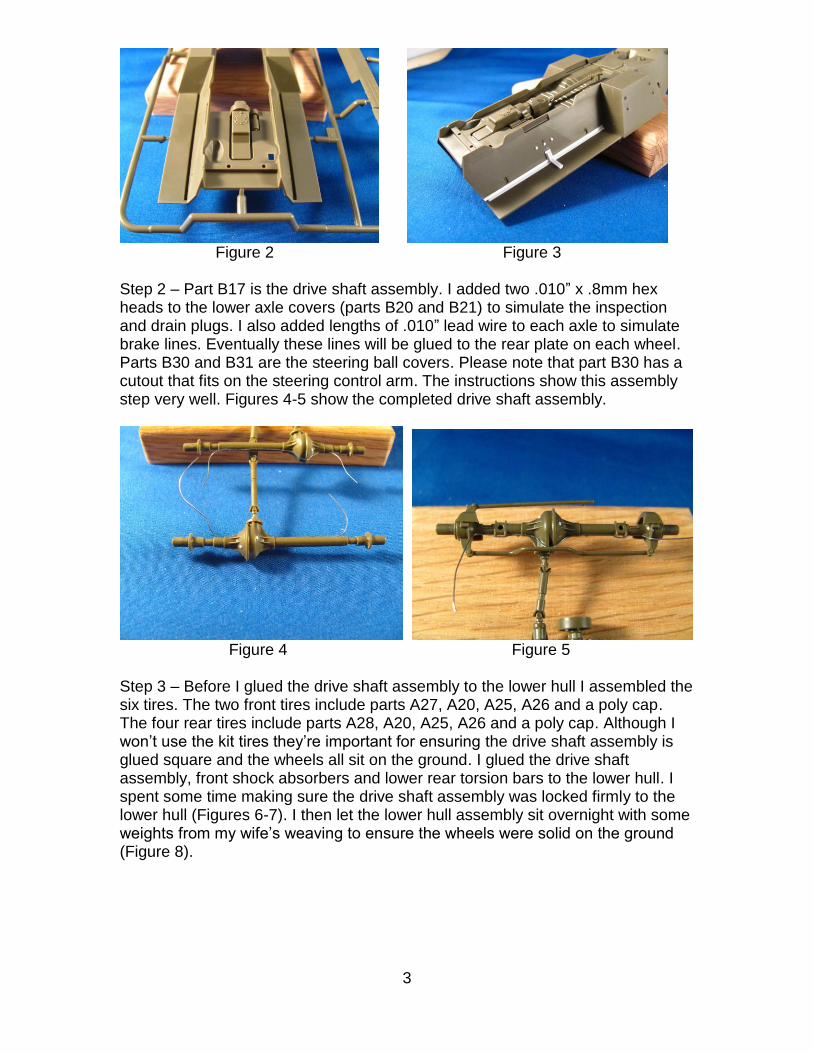
critical if you leave the fenders off as many of the suspension parts are somewhat exposed to the flashlight of an inquisitive judge. I elected to cleanup and build the suspension as one step. I did this because building the suspension is the most critical part of constructing a wheeled vehicle. The suspension must be square with all the wheels touching the ground. Step 1 – In this step you glue the hull floor (part D32) to the hull tub (part C16). I also started the mold seam cleanup on all the suspension parts A15 (rear suspension plates), A30 (rear springs and torsion bars), B15 (main drive shaft), B17 (drive shift unit), B18 (transfer case cover), B20 (front and rear axle covers), B21 (middle axle cover), B30 (right steering ball cover), B31 (left steering ball cover), B46 (steering mechanism), A9 (front shock absorbers), A12 (lower rear torsion bars), A29 (right front spring assembly), A31 (left front spring assembly), A10 (rear shock absorbers) and A11 (rear shock absorbers). I did this cleanup using a new No. 11 X-acto blade and several pieces of 800-grit sand paper. I spent a considerable time cleaning the seam lines because I’m building this model without the fenders. The following is the detailing I used for the rear wheel wells: Figure 1 shows the support and reinforcing strip on the inside of the rear wheel wells. The hull tub has open slots where the rear hull sides and the fender bottoms meet. I cut four pieces of .015” x .040” x 60mm Evergreen plastic strips to act as filler for these slots. I then marked the center of the wheel well and added a piece of .015” x .100” x .125” Evergreen plastic strip on each side at the centerline. To simulate the supports, I cut a piece of U-channel .060” x 3/32” for the lower support and .060” x 8/32” for the upper support. I added three .015” x 1.2mm hex heads to simulate the bolt heads on the hull side. I also added two .010” x .8mm hex heads to simulate the bold heads on the rear cross member. Figures 2-3 show the hull tub after these detail steps were completed.
Figure 1
3
Figure 2 Figure 3 Step 2 – Part B17 is the drive shaft assembly. I added two .010” x .8mm hex heads to the lower axle covers (parts B20 and B21) to simulate the inspection and drain plugs. I also added lengths of .010” lead wire to each axle to simulate brake lines. Eventually these lines will be glued to the rear plate on each wheel. Parts B30 and B31 are the steering ball covers. Please note that part B30 has a cutout that fits on the steering control arm. The instructions show this assembly step very well. Figures 4-5 show the completed drive shaft assembly.
Figure 4 Figure 5 Step 3 – Before I glued the drive shaft assembly to the lower hull I assembled the six tires. The two front tires include parts A27, A20, A25, A26 and a poly cap. The four rear tires include parts A28, A20, A25, A26 and a poly cap. Although I won’t use the kit tires they’re important for ensuring the drive shaft assembly is glued square and the wheels all sit on the ground. I glued the drive shaft assembly, front shock absorbers and lower rear torsion bars to the lower hull. I spent some time making sure the drive shaft assembly was locked firmly to the lower hull (Figures 6-7). I then let the lower hull assembly sit overnight with some weights from my wife’s weaving to ensure the wheels were solid on the ground (Figure 8).

4
Figure 6 Figure 7
Figure 8
The front plate (part C7) has six punch out marks which need to be filled. I added the two tow clevis attachments (part A4) to the front plate. I cleaned the mold seams from these parts after they were secure to the front plate (Figures 9-10). I added the front plate and front springs (parts A29 and A31) to the lower hull. The springs should be secure to the front plate. However, I had a gap that I filled with a shim of .010” sheet plastic. I added .8mm hex heads to the attachment points of each rear torsion bar (Figures 11-12). Finally, I glued the transfer case brush guard (part B13) to the lower hull.
Figure 9 Figure 10

5
Figure 11 Figure 12 Step 4 – The rear hull plate (part C15) is configured so you can open holes on its left side to attach a first aid case (part B16). If you are building a Korean War M8 then you’ll want to open these holes. I filled these holes with .062” (1/16”) plastic rod and when dry cut them flush to the rear plate (Figures 13-14). Next, I added the two tow clevis attachments (parts A3) and tow pintle plate (part B6) to the rear plate. I cleaned the mold seams from the tow clevis attachments after they were secure to the rear plate. I cleaned the mold seams from the muffler and exhaust pipe assembly (part B37). I used a #65 drill bit to open the end of the exhaust pipe. I glued the rear shock absorbers (parts A10 and A11) and rear suspension support (part B33) to the rear suspension. Finally, I glued the muffler and exhaust pipe assembly and rear plate to the lower hull (Figure 15).
Figure 13 Figure 14
Figure 15

6
Project Addendum (Steps 1-4)
In response to some email requests and my affliction with terminal AMS, I thought I’d share with you some additional detailing steps for the undercarriage of the M-8. Note these details are not really visible if you plan to build your model with the fenders on or highly weather the undercarriage. Brake Lines: In Step 2, I discussed adding .010” lead wire to simulate break lines on the axles. In the “Allied-Axis, the photo Journal of the Second World War, Issue 5,” there is a diagram of the brake line system for the M-8 (Figure 16). I used this diagram and a couple of pictures (Figures 17-18) from the CD that Ashley provided us as reference guides to lay in the brake lines.
Figure 16
Figure 17 Figure 18 I used .010” lead wire for the brake lines running down the frame and .015” lead wire as the armor covered connecting line to each axle. I used a .020” x.030” plastic square to simulate the connecting points. I also used a 1mm x 2mm strip of lead foil to simulate the brake line hangers (Figures 19-21).

7
Figure 19 Figure 20
Figure 21
Hull Bumper Stops: Bumper stops are designed to prevent the suspension from coming into contact with the hull. On the M-8, these are triangle metal supports with a rubber bumper bolted to the bottom. They are attached to the hull just above each axle (Figures 22-23).
Figure 22 Figure 23 To simulate these devices I laminated two squares of .015” x .060” x .060” plastic together to get the proper thickness. I then cut diagonally across each square to get my triangle shaped support. I added a .020” x .030” piece of plastic round to the bottom of each triangle to simulate the bumper. I then glued each bumper stop to the hull about each axle (Figures 24-26).

8
Figure 24 Figure 25
Figure 26
Rear Suspension Bolt Detail: One of the pictures from Ashley’s CD showed additional bolt detail where the rear suspension unit is attached to the hull. I used 1.2mm x .015” hex heads to simulate this detail (Figures 27-28).
Figure 27 Figure 28


![Medical Bloggers Panel [4 Aud 1215 Mesko]](https://static.fdocuments.net/doc/165x107/558ecdb91a28abdb7e8b45e5/medical-bloggers-panel-4-aud-1215-mesko.jpg)