
AMFC Technical Challenges and Status: From Single … = 1;3 bar(g) 30mm ... • Fast rate of water...
26
© 2016 by Elbit Systems | Elbit Systems Proprietary AMFC Technical Challenges and Status: From Single Cell to Stack System Miles Page Elbit Systems Energy Group Shimshon Gottesfeld Fuel Cell Consulting Ltd. AMFC Workshop 2016
Transcript of AMFC Technical Challenges and Status: From Single … = 1;3 bar(g) 30mm ... • Fast rate of water...

© 2016 by Elbit Systems | Elbit Systems Proprietary
AMFC Technical Challenges and Status:
From Single Cell to Stack System
Miles Page
Elbit Systems Energy Group
Shimshon Gottesfeld
Fuel Cell Consulting Ltd.
AMFC Workshop 2016

© 2016 by Elbit Systems | Elbit Systems Proprietary
From Single Cell to System – Key Challenges
• AMFC Stack
Selected issues / research needs defined at
2011 AMFC Workshop: – Optimize operation conditions (basically effective water management)
– Solution for carbonation issue
– Higher anode activity
– Membrane - operation at T > 80°C; higher water mobility
• Advancement in state of the art 2011 2016
– 200mW/cm2 MEA @0.5V • 1000mW/cm2 @0.5V (Elbit; [Zhuang et al.[1] under O2])
– 2kW net stack system • 2kW net system (Cellera 2014)
• Presumed 10’s of kW system by Daihatsu (albeit KOH-soaked MEA’s)

© 2016 by Elbit Systems | Elbit Systems Proprietary
AMFC Status – Single (well-humidified) Cell
• Performance level of Proton Exchange Membrane (PEM) fuel
cells is within reach, however:
– Air humidification and overall water management are critical
– CO2 handling adds to system complexity in operation at lower Tcell
Polarization curve – 5cm2 H2/Air
Pt-free Ca, Pt-catalyzed An;
CO2-free air
Tcell = Tair(humf) = 75°C
Pair; PH2 = 1;3 bar(g)
30mm thick, polyhydrocarbon
membrane

© 2016 by Elbit Systems | Elbit Systems Proprietary
Selected Issues & Research Needs
– Higher anode activity
– Membrane - operation at T > 80C / water mobility
• Anode activity: significant progress has been made
– Near-Pt activity with Pd-based catalyst [2];
– Pt-containing bimetallics show activity greater than Pt [3];
– Advances in fundamental understanding of alkaline HOR [4,5]
• Anode challenge today: also substantially water management
• Membrane:
– Tokuyama A201 – technology of ca. 2008 – is still the leading commercial
“standard” membrane
– i.e. “membrane/ionomer issues” – including the
need for higher operation temperature and
higher water mobility – have not been adequately resolved!
KEY BOTTLENECK !

© 2016 by Elbit Systems | Elbit Systems Proprietary
Key System-Level Challenges
• Water management
– Target : Operation with no external humidification
– Challenge : Water generation on the fuel side creates propensity
for anode flooding and cathode dry-out
• CO2 immunity
– Target : continuous operation with ambient air feed
– Challenge: direct feed of ambient air causes loss of 50% of the
power vs. operation on air free of CO2
• These challenges have been addressed significantly, nevertheless,
• Substantial room remains for further improvement

© 2016 by Elbit Systems | Elbit Systems Proprietary
• 6-month 2kW H2/Air stack-system test
• Live site backup capability
• Aluminum hardware; air-cooled
• Cathode water exchanger / dry anode
• Pressure - ambient air / 1.5bar(g) H2
Field-tested 2kW AMFC System (Cellera)

© 2016 by Elbit Systems | Elbit Systems Proprietary
AMFC Status – Stack operation
• No measurable degradation over 5000h (intermittent operation)
• Optimized shut-off/restart conditions proved critical

© 2016 by Elbit Systems | Elbit Systems Proprietary
AMFC SYSTEM: CO2 IMMUNITY

© 2016 by Elbit Systems | Elbit Systems Proprietary
The “CO2 Immunity” Subsystem
• CO2 sequestration subsystem upstream the cathode
developed and demonstrated at Cellera (now Elbit Systems)
[6]
– Two step process; each lowering the CO2 level by ~10x
– Thereby reducing CO2 in the
cathode inlet to <5 ppm
– First step: Thermally regenerated
polymeric active material
– Second step: completes removal
of ~99% of CO2 with a strongly
CO2-bonding inorganic solid

© 2016 by Elbit Systems | Elbit Systems Proprietary
Upper plot: Carbonation and de-carbonation
(lowering pCO2 under same constant current):
• ~100h to full recovery at any given current
• However: significant partial recovery in
10’s of minutes
• Lower plot: Applying a current well above
operation point: effective full recovery
at the operation point
1) At “CO2 OFF”, INCREASE CURRENT:
Greater proportion of (H)CO3(2)-
replaced at the anode by “new OH- ”
2) Return to original current, and
voltage returns quickly to
original value
60 °C;
arbitrary
pCO2
Handling CO2 contamination

© 2016 by Elbit Systems | Elbit Systems Proprietary
The “CO2 Immunity” Subsystem
• Corrective measures demonstrated
– CO2 sequestration subsystem upstream the cathode
– De-carbonation within the cell by step of high current
• Addressing CO2 sensitivity - path forward:
– Increase operation temperature to facilitate decarbonation and
allow higher “CO2 slip”
• CO2 sequestration technology is advancing independent of AMFC:
o Isotherms with >30% w/w reversible CO2 capture [7]
o Improvements in T swing specs
(increasing adsorption T / decreasing desorption T)

© 2016 by Elbit Systems | Elbit Systems Proprietary
AMFC SYSTEM:
WATER MANAGEMENT

© 2016 by Elbit Systems | Elbit Systems Proprietary
Water in the AMFC
• AMFC Hydration challenge is especially significant because
– The cathode is actively consuming water and
– The cathode uses high gas flow (20% O2 @ 2.0 stoichiometry)
which causes substantial removal of water from the cell into sub-
saturated air

© 2016 by Elbit Systems | Elbit Systems Proprietary
AMFC System: Loss of water of hydration
strong impact on performance
• Diffusivities of H+ and
OH- in the ionomer drop
substantially with drop in
the water content [8]
Strong effect of partial
dehydration On
conductivity for OH- ion-
conducting ionomers
* (FAA-3 membrane by Fumatech)
*

© 2016 by Elbit Systems | Elbit Systems Proprietary
240 cm2 Single-cell: Water Imaging
• Neutron Imaging “through-plane” (limited to
single cell, giving a full lateral water distribution
image)
• Horizontal single channels used for
serpentine anode flow field
• Multi-serpentine (11 channels, 5 passes)
flow field on cathode side
• Dry H2; humidified air (80% RH);
Cell T = 60°C
Yellow indicates “dry”;
more water more blue
Yellow
Ca IN An IN
Ca OUT An OUT
active area

© 2016 by Elbit Systems | Elbit Systems Proprietary
Ca IN An IN
Ca OUT An OUT
active area
• Operation with dead-ended anode and
periodic gas purge (3s per 3 mins)
Ca OUT An OUT
“Dry” section of MEA propagating
from Cathode inlet
Excess water removal
at Ca exhaust
240 cm2 single-cell: Water Imaging

© 2016 by Elbit Systems | Elbit Systems Proprietary
Consequences
• Water exchanger on the cathode side is a key
component of the AMFC water-management
subsystem, targeting highest dew point for
the cathode inlet
• Fast rate of water transport across the cell
membrane into the cathode is critical for high
AMFC performance

© 2016 by Elbit Systems | Elbit Systems Proprietary
RESEARCH NEEDS

© 2016 by Elbit Systems | Elbit Systems Proprietary
Membrane/ionomer upgrade is a
key system requirement
• [ increase Tcell ] x [ decrease tmem ] x [ increase sion ]
• With the main (system) benefits being:
– Facilitated water management
– Reduced CO2 filtration requirements
• Obtained by
– </= ~15 mm thick membranes of good mechanical integrity
– Higher ionomer/membrane stability at 80 °C+
© 2016 by Elbit Systems | Elbit Systems Proprietary
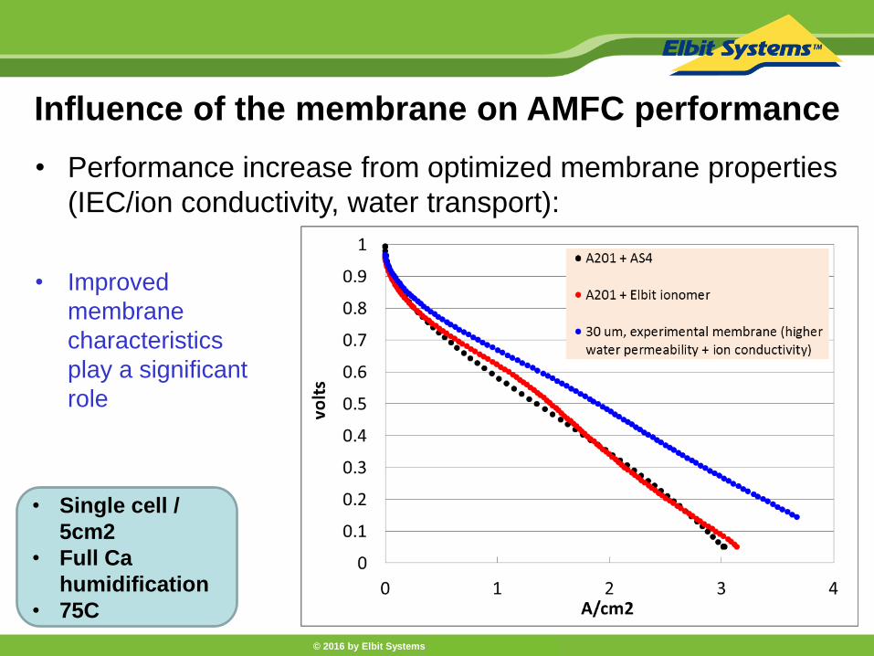
Influence of the membrane on AMFC performance
• Performance increase from optimized membrane properties
(IEC/ion conductivity, water transport):
• Improved
membrane
characteristics
play a significant
role
• Single cell /
5cm2
• Full Ca
humidification
• 75C

© 2016 by Elbit Systems | Elbit Systems Proprietary
Influence of the membrane on AMFC performance
• 30 micron membrane, ~60 mS/cm (OH- at 75C)
• 10 micron membrane, ~20 mS/cm (OH- at 75C)
• Thin membrane
is potentially
more beneficial
than simple
increase in
conductance

© 2016 by Elbit Systems | Elbit Systems Proprietary
AMFC performance recorded with
different anode catalysts
• Consequences of
advancing to the low-cost
AMFC anode – arising from
low anode catalyst activity
together with low catalyst
utilization [9] and limited
rate of H2 access in a
“flooded” anode*
* Reminder: 2x water generation rate
• Single cell / 5cm2
• Full Ca humidification
• 75C
• 30 micron membrane

© 2016 by Elbit Systems | Elbit Systems Proprietary
Present performance of
AMFC and PEMFC of low cell Pt loading
• Performance boost
still needed to match
low-Pt PEM cells
• Membrane improvements
can certainly help, but
improved intrinsic activity
and novel catalyst layer
structures are clearly
required
© 2016 by Elbit Systems | Elbit Systems Proprietary
Concluding Remarks
• Primary goal today from the system point of view is:
Minimize the complexity and cost of applying system fixes
to problems caused by materials properties limitations
• Reduce cathode dry-out losses through better internal water
transport characteristics
• Allow higher temperature operation with advanced membranes
which combine high T tolerance, water permeability and
conductivity

© 2016 by Elbit Systems | Elbit Systems Proprietary
Acknowledgements
Elbit Systems -
• Dr Yair Paska
• Yair Binyamin
• Dr Charly Azra
Cellera -
• Dr Dario Dekel
• Dr Nir Haimovitch
• Dr Pierre Boillat, Paul Scherrer Institut (Neutron Imaging)

© 2016 by Elbit Systems | Elbit Systems Proprietary
References
1. Wang, Y. et al., Energy Environ. Sci. 2015, 8, p177
2. Bakos, I. et al., Electrochim. Acta 2015, 176, p1074
3. Elbert, K. et al., ACS Catalysis 2015, 5, p6764
4. Strmcnik, D. et al., Nature Chem. 2013, 5, p300
5. Durst, J. et al., Energy Environ. Sci. 2014, 7, p2255
6. Gottesfeld, S., US Patent #8,895,198 B2, 2014
7. Maity, D. et al., Cryst. Growth Des. 2016, 16, p1162
8. Marino, M. et al., J. Membrane Sci. 2014, 464, p61
9. Woodruff, M. et al.,Electrochem. Comm. 2015, 61, p57
10. Steinbach, A. et al., DOE Annual Merit Review 2015 https://www.hydrogen.energy.gov/pdfs/progress15/v_c_1_steinbach_2015


![Biomechanics Laboratory. arXiv:1811.12607v4 [cs.CV] 28 May ... · Learning Dynamics from Kinematics: Estimating 2D Foot Pressure Maps from Video Frames Christopher Funk 1;3, Savinay](https://static.fdocuments.net/doc/165x107/5f800991425dd02abe5bf649/biomechanics-laboratory-arxiv181112607v4-cscv-28-may-learning-dynamics.jpg)