
AMESim Advanced Modeling E Simulations of engineering systems. … · Typical components: pipe...
20
AMESim = Advanced Modeling Environment for performing Simulations of engineering systems. AMESim is a 1D lumped parameter time domain simulation platform. AMESim uses symbols to represent individual components within the system which are either: • based on the standard symbols used in the engineering field such as ISO symbols for hydraulic components or block diagram symbols for control systems or when no such standard symbols exist: • symbols which give an easily recognizable pictorial representation of the system. AMESim
Transcript of AMESim Advanced Modeling E Simulations of engineering systems. … · Typical components: pipe...
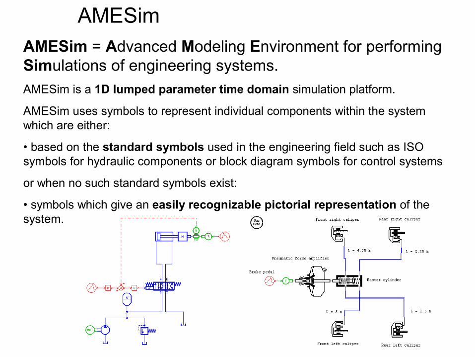
AMESim = Advanced Modeling Environment for performing Simulations of engineering systems.AMESim is a 1D lumped parameter time domain simulation platform.
AMESim uses symbols to represent individual components within the system which are either:
• based on the standard symbols used in the engineering field such as ISO symbols for hydraulic components or block diagram symbols for control systems
or when no such standard symbols exist:
• symbols which give an easily recognizable pictorial representation of the system.
AMESim
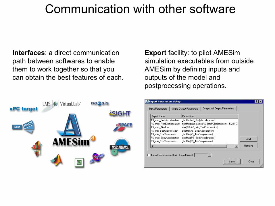
Interfaces: a direct communication path between softwares to enable them to work together so that you can obtain the best features of each.
Export facility: to pilot AMESim simulation executables from outside AMESim by defining inputs and outputs of the model and postprocessing operations.
Communication with other software
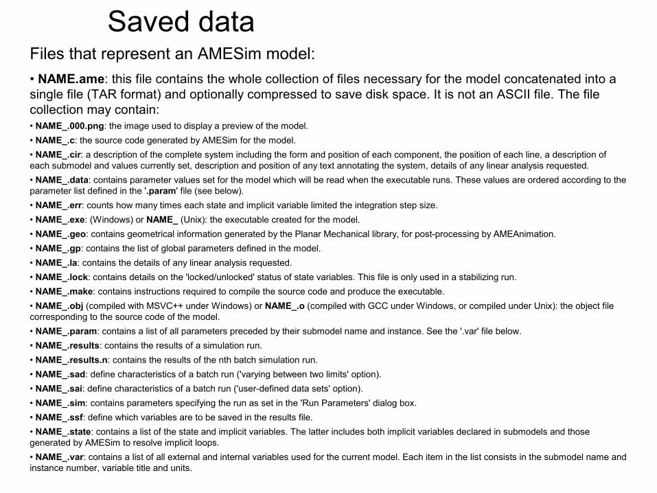
Files that represent an AMESim model:• NAME.ame: this file contains the whole collection of files necessary for the model concatenated into a single file (TAR format) and optionally compressed to save disk space. It is not an ASCII file. The file collection may contain:• NAME_.000.png: the image used to display a preview of the model.• NAME_.c: the source code generated by AMESim for the model.• NAME_.cir: a description of the complete system including the form and position of each component, the position of each line, a description of each submodel and values currently set, description and position of any text annotating the system, details of any linear analysis requested.• NAME_.data: contains parameter values set for the model which will be read when the executable runs. These values are ordered according to the parameter list defined in the '.param' file (see below).• NAME_.err: counts how many times each state and implicit variable limited the integration step size.• NAME_.exe: (Windows) or NAME_ (Unix): the executable created for the model.• NAME_.geo: contains geometrical information generated by the Planar Mechanical library, for post-processing by AMEAnimation.• NAME_.gp: contains the list of global parameters defined in the model.• NAME_.la: contains the details of any linear analysis requested.• NAME_.lock: contains details on the 'locked/unlocked' status of state variables. This file is only used in a stabilizing run.• NAME_.make: contains instructions required to compile the source code and produce the executable.• NAME_.obj (compiled with MSVC++ under Windows) or NAME_.o (compiled with GCC under Windows, or compiled under Unix): the object file corresponding to the source code of the model.• NAME_.param: contains a list of all parameters preceded by their submodel name and instance. See the '.var' file below.• NAME_.results: contains the results of a simulation run.• NAME_.results.n: contains the results of the nth batch simulation run.• NAME_.sad: define characteristics of a batch run ('varying between two limits' option).• NAME_.sai: define characteristics of a batch run ('user-defined data sets' option).• NAME_.sim: contains parameters specifying the run as set in the 'Run Parameters' dialog box.• NAME_.ssf: define which variables are to be saved in the results file.• NAME_.state: contains a list of the state and implicit variables. The latter includes both implicit variables declared in submodels and those generated by AMESim to resolve implicit loops.• NAME_.var: contains a list of all external and internal variables used for the current model. Each item in the list consists in the submodel name and instance number, variable title and units.
Saved data
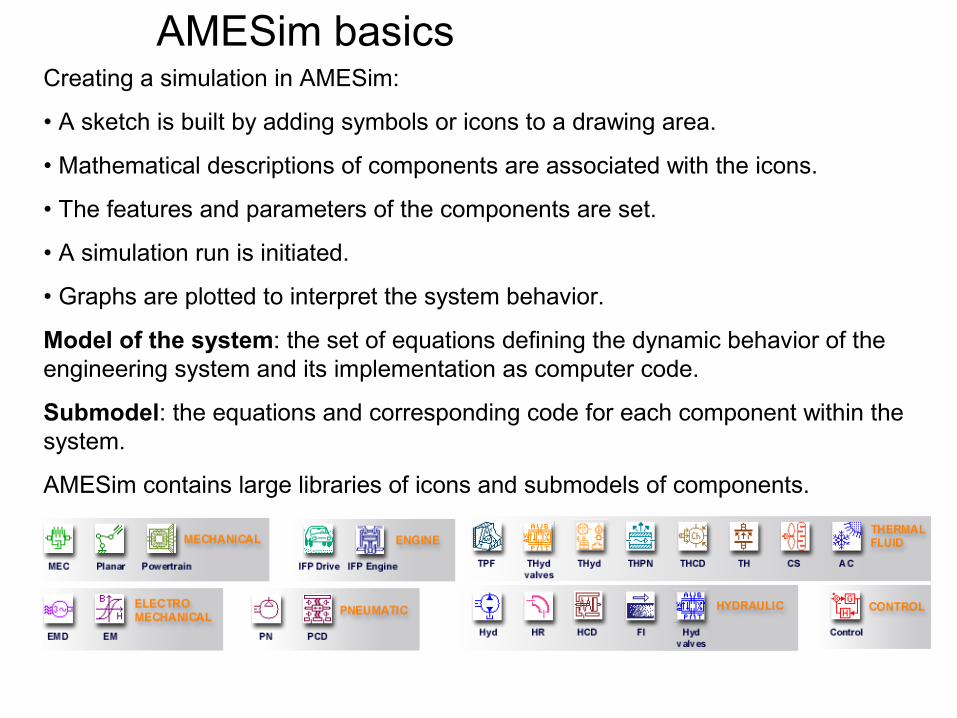
Creating a simulation in AMESim:
• A sketch is built by adding symbols or icons to a drawing area.
• Mathematical descriptions of components are associated with the icons.
• The features and parameters of the components are set.
• A simulation run is initiated.
• Graphs are plotted to interpret the system behavior.
Model of the system: the set of equations defining the dynamic behavior of the engineering system and its implementation as computer code.
Submodel: the equations and corresponding code for each component within the system.
AMESim contains large libraries of icons and submodels of components.
AMESim basics
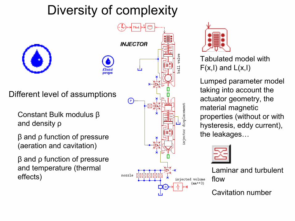
Diversity of complexity
Constant Bulk modulus β and density ρ
β and ρ function of pressure (aeration and cavitation)
β and ρ function of pressure and temperature (thermal effects)
Tabulated model withF(x,I) and L(x,I)
Lumped parameter model taking into account the actuator geometry, the material magnetic properties (without or with hysteresis, eddy current), the leakages…
Laminar and turbulent flow
Cavitation number
Different level of assumptions
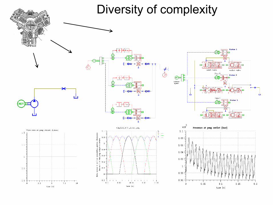
Diversity of complexity
...
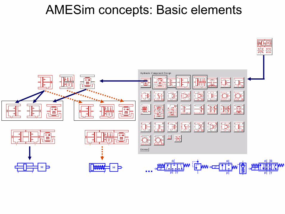
AMESim concepts: Basic elements
Elementary technical functions
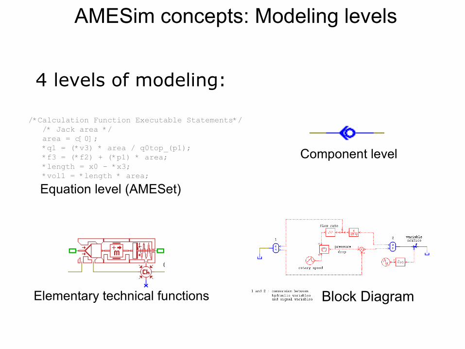
/*Calculation Function Executable Statements*/ /* Jack area */ area = c[0]; *q1 = (*v3) * area / q0top_(p1); *f3 = (*f2) + (*p1) * area; *length = x0 - *x3; *vol1 = *length * area;
Equation level (AMESet)
4 levels of modeling:
Component level
Block Diagram
AMESim concepts: Modeling levels
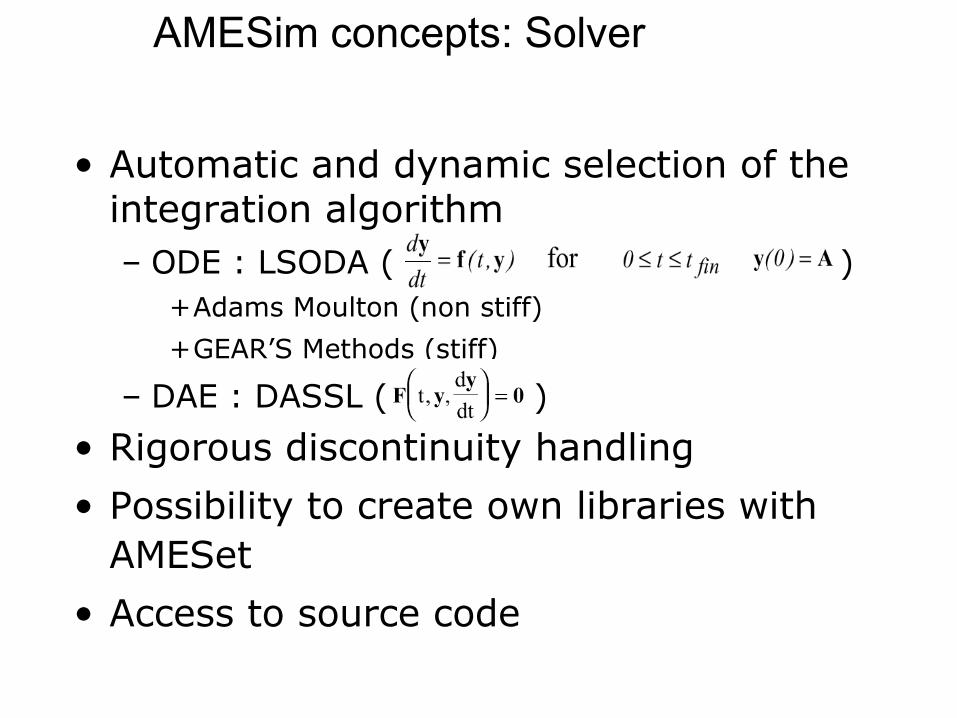
• Automatic and dynamic selection of the integration algorithm– ODE : LSODA ( )
+Adams Moulton (non stiff)
+GEAR’S Methods (stiff)
– DAE : DASSL ( )
• Rigorous discontinuity handling
• Possibility to create own libraries with AMESet
• Access to source code
AMESim concepts: Solver
pPQPQA
QB
P1
P2
Q1
Q2
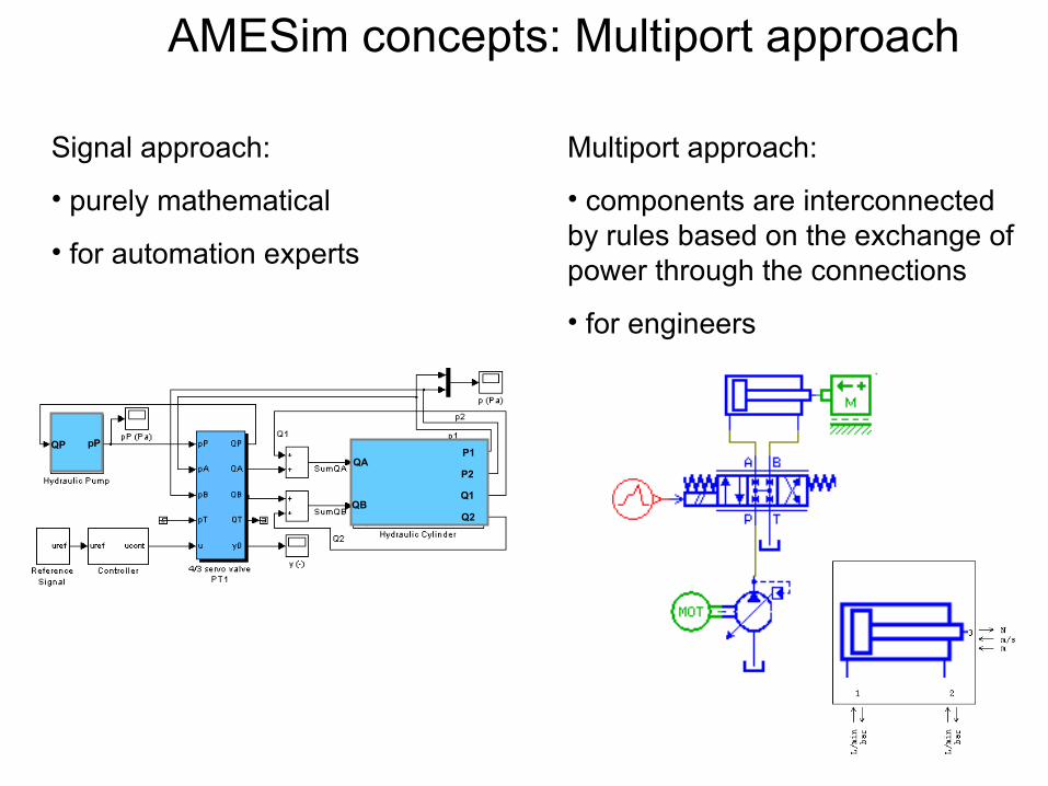
Signal approach:
• purely mathematical
• for automation experts
Multiport approach:
• components are interconnected by rules based on the exchange of power through the connections
• for engineers
AMESim concepts: Multiport approach
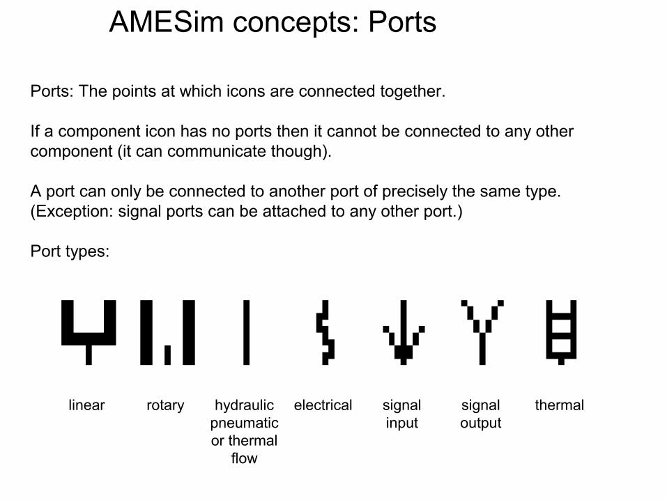
Ports: The points at which icons are connected together.
If a component icon has no ports then it cannot be connected to any other component (it can communicate though).
A port can only be connected to another port of precisely the same type. (Exception: signal ports can be attached to any other port.)
Port types:
linear rotary hydraulicpneumaticor thermal
flow
electrical signal input
signal output
thermal
AMESim concepts: Ports
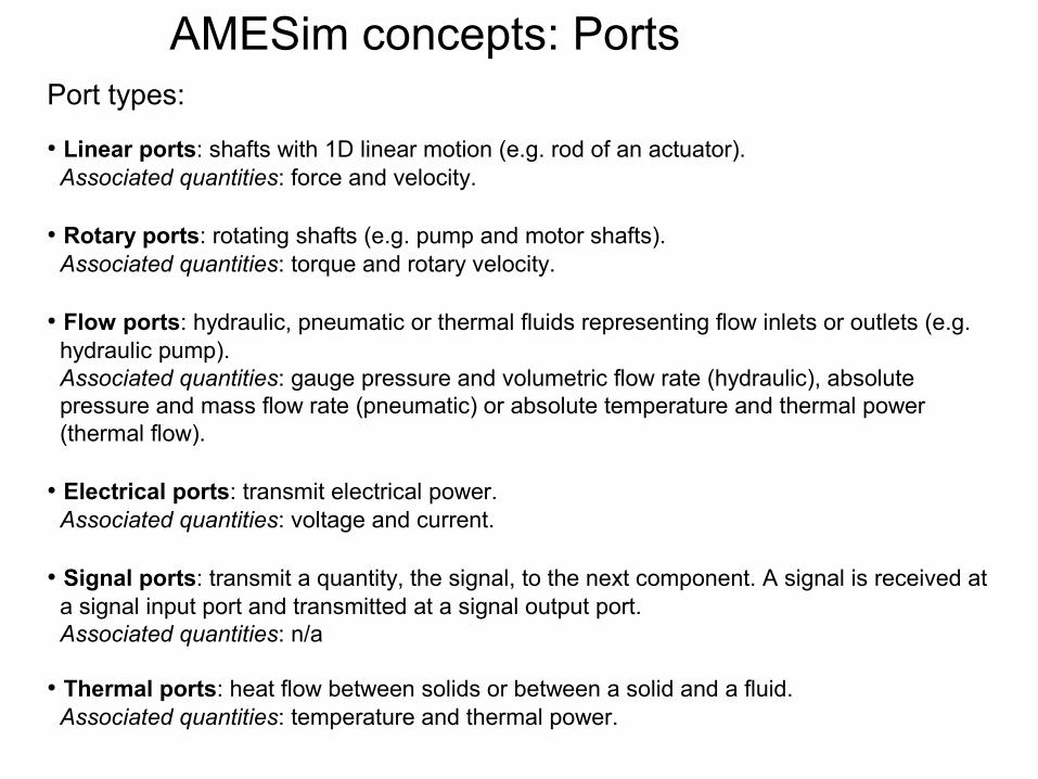
Port types:
• Linear ports: shafts with 1D linear motion (e.g. rod of an actuator). Associated quantities: force and velocity.
• Rotary ports: rotating shafts (e.g. pump and motor shafts). Associated quantities: torque and rotary velocity.
• Flow ports: hydraulic, pneumatic or thermal fluids representing flow inlets or outlets (e.g. hydraulic pump). Associated quantities: gauge pressure and volumetric flow rate (hydraulic), absolute pressure and mass flow rate (pneumatic) or absolute temperature and thermal power (thermal flow).
• Electrical ports: transmit electrical power. Associated quantities: voltage and current.
• Signal ports: transmit a quantity, the signal, to the next component. A signal is received at a signal input port and transmitted at a signal output port. Associated quantities: n/a
• Thermal ports: heat flow between solids or between a solid and a fluid. Associated quantities: temperature and thermal power.
AMESim concepts: Ports
MechanicalSince all kinds of systems usually interface with some form of mechanical system these components complement other libraries. The library is often also used in isolation to simulate complete mechanical systems. Linear and rotary motion elements included.Typical components: masses, springs, dampers, contact elements, backlashes, frictions, levers and gear ratios, elastic cables and sheave wheels.
ControlThis library contains all the components necessary to control, measure and observe your system. Many signals, sources and mathematical functions are included. This library may be used to create block-diagram models of systems (if desired).Typical components: sources, sinks, gains, integrators, lag networks, transfer functions, equation blocks, table lookup blocks and many more.
AMESim concepts: Libraries
AMESim concepts: Libraries
HydraulicThe hydraulic library contains many general hydraulic components (pumps, lines, valves, actuators) suitable for simulating ideal dynamic behavior based on component performance parameters.Typical components: fluid properties, nodes, tanks, pressure and flow sources, accumulators, several valves, orifices, pumps, motors, and actuators.
Hydraulic LinesBy connecting components with a mouse click, the user can select between 10 different hydraulic line models. The models vary in complexity to allow for gradual model complexity increase. Some of the advanced models take full wave effects, cavitation, frequency dependant friction, compressibility and line wall compliance into account.
AMESim concepts: Libraries
Hydraulic Component Design (HCD)This library contains the basic building blocks of any hydromechanical system. Models built with this category include anything from diesel injectors to servo valves or semi-active dampers. As the submodels are component based, interpretation of the model layout is intuitive.Typical components: mass with frictions, pistons, leakages, spools with annular orifice, with orifice hole, with slot orifices, poppets with sharp edge seat, with conical seat, with no seat, with plain seat, ball poppets, orifice with flow number and cavitation number
Hydraulic Resistance (HR)In certain low-pressure/high flow rate applications (e.g. lubrication systems) it is essential to predict the overall pressure drop due to friction and restrictions thus ensuring proper operation of the system. The hydraulic resistance library allows to calculate the steady state pressure drop based on the geometrical layout.Typical components: pipe components, junctions and special orifice geometries.
AMESim concepts: Libraries
Pneumatic (PN)Contains component level models (valves, accumulators, actuators, pipes) to model large networks, and basic elements (volume, restrictions, springs, spools) to design complex pneumatic components (example: pressure regulator for methane injection).Typical components: gas properties, pressure and flow sources, valves, orifices and actuators
Pneumatic LinesFor connecting pneumatic components, there are 8 different pneumatic line models. The models vary in complexity to allow for gradual model complexity increase. Some of the advanced models take full wave effects, frequency dependant friction, compressibility and line wall compliance into account.
AMESim concepts: Libraries
Thermal (TH)The thermal library is used to study heat transfer in solids and interaction between the thermal hydraulic and the thermal pneumatic libraries in order to analyze complex system (e.g. car engine). The thermal components allow the calculation of heat flow and losses through convection, radiation or conduction elements.Typical components: Thermal solid properties, temperature and heat flow sources, thermal capacity, conductive, convective and radiative exchange
Thermal hydraulic (THH)Similar to the elements of the Hydraulic Resistance library, the ThermalHydraulic components compute the heat generated by friction in the pipes, bends and restrictions and allow heat transfer with the circuit environment.Typical components: similar to the hydraulic resistance library
AMESim concepts: Libraries
Thermal Hydraulic Component Design (THCD)Similar to the HCD library, but with the inclusion of thermal effects such as heating of fluids and thermal inertias.Typical components: similar to the HCD library
Thermal Pneumatic (THPN)Used for modelling heat exchange between pneumatic networks and their environment. The library includes elementary geometry elements (pipes, restrictions, bends, volumes, junctions) equipped with a thermal port to transfer heat to solids. It also include a gas / liquid heat exchanger to link pneumatic networks with cooling circuits.Typical components: similar to the hydraulic resistance library
AMESim concepts: Libraries
Cooling Systems (CS)This library allows engines and other thermal machines to be modeled from a global point of view. E.g. combination of models for the cooling system, lubrication system, and exhaust system can be used to study the complete thermal behavior of an engine.Typical components: pumps, engine, radiators, thermostats, heater component, expansion tank, EGR, condenser and compressor
Filling (FI)The filling library is similar to the hydraulic resistance library, but specialized for determination (for instance) of the time taken to fill the lubrication circuits of an engine with oil during startup. The models usually contain two working fluids (air and oil) although the working fluids are not considered to mix.Typical components: similar to the hydraulic resistance library
AMESim concepts: Libraries
Powertrain (TR)This library contains components which allows to model systems such as driveline or complete gearboxes, including vibration and loss effects. Coupling with the hydraulic and magnetic library components can lead to models such as an automatic gearbox.Typical components: engine, crankshaft-piston, torque converter, clutch friction, CVT, gears, idle gears, synchronizer, band brake, multi-discs clutch and brake, planetary geartrain, transfer box, differential, tire, vehicle, universal joint.
Electro-Mechanical (EM)This library contains elements such as air gaps, metal elements, magnets and coils to construct a 1D equivalent of a magnetic circuit such as a solenoid. Contains dynamic effects such as hysteresis and electric properties.Typical components: magnetic properties, solenoid models based on look-up tables, coils, axial and radial magnetic elements, air gaps, leakages, permanent magnet, common command circuits, resistor, capacitor, inductor, diode, switch, nodes, earth, current and voltage sources.