AMERISTAR SECURITY PRODUCTS CITYSCAPE GATE · AMERISTAR SECURITY PRODUCTS CITYSCAPE GATE...
34
AMERISTAR SECURITY PRODUCTS CITYSCAPE GATE Installation, Operation and Maintenance Manual
Transcript of AMERISTAR SECURITY PRODUCTS CITYSCAPE GATE · AMERISTAR SECURITY PRODUCTS CITYSCAPE GATE...

AMERISTAR SECURITY PRODUCTS
CITYSCAPE GATE
Installation, Operation and Maintenance Manual

Ameristar Fence Products 1555 N Mingo Road Tulsa OK 74116 Ph: 918 835 0898, Fax: 918 835 1002
www.ameristarfence.co 2
TABLE OF CONTENTS
PREFACE... .................................................................................................................................... 4 CONVENTIONS USED IN THIS DOCUMENTS...............................................................................5 WARNING AND CAUTIONS .......................................................................................................... 5 Safety Warning and Caution Overview................................................................................................5 Maintence, Service and Repair Warnings.......................................................................................... 6 Pedestrian and Personnel Safety Warnings........................................................................................6 Vehicle Safety Warnings......................................................................................................................6 Instrusion Incident Damage Caution....................................................................................................6 General Safety Precautions.................................................................................................................7 Working Under Equipment Warnings................................................................................................. 7 Cold Weather Cautions...................................................................................................................... 8 Vehicle Speed Cautions..................................................................................................................... 8 Owner/ Operator Responsibilities.......................................................................................................9 COSHH................................................................................................................................................9 Electrical Safety................................................................................................................................10 Operational Safety............................................................................................................................10 PRODUCT DESCRIPTION............................................................................................................. 11 Introduction ......................................................................................................................................11 Available finishes .............................................................................................................................12 Structure .......................................................................................................................................... 12 Hinging options ................................................................................................................................13 Lengths available ..............................................................................................................................13 INSTALLATION .............................................................................................................................. 14 Excavating the trench ...................................................................................................................... 14 Concrete filling .................................................................................................................................17 Installing hoses and control cables ...................................................................................................18 Lifting the City Scape Gate................................................................................................................19 CONTROL PANEL ...........................................................................................................................20 General ........................................................................................................................................... 20 Mains isolation .............................................................................................................................. 20 Control equipment .......................................................................................................................... 20 TO LOCK AND UNLOCK THE GATE ............................................................................................ 22 Push button control ......................................................................................................................... 22 To open the gate ............................................................................................................................. 22 To close the gate ............................................................................................................................. 23 MAINTENANCE ...............................................................................................................................24 Weekly checks ................................................................................................................................ 24 Six monthly cleaning ....................................................................................................................... 24 Level adjustment ............................................................................................................................. 25 Locking pin position sensing ........................................................................................................... 26 To remove the flange and sleeve ................................................................................................... .26 To remove the cartridge .................................................................................................................. 27 To refit the cartridge ........................................................................................................................ 27 To refit the sleeve ............................................................................................................................ 27 SERVICE .........................................................................................................................................28

Ameristar Fence Products 1555 N Mingo Road Tulsa OK 74116 Ph: 918 835 0898, Fax: 918 835 1002
www.ameristarfence.co 3
Appendix A: Aeroshell Fluid 41.................................................................................................... 29 Hazards Identification ...................................................................................................................... 29 First Aid Measures .......................................................................................................................... 30 Advice to Doctor ............................................................................................................................. 30 Fire Fighting Measures ................................................................................................................... 30 Accidental Release Measures ........................................................................................................ 31 Handling and Storage ..................................................................................................................... 31 Ecological Information .................................................................................................................... 32 Waste, Product and Container Disposal ........................................................................................ 32 Appendix B: Standard Forms ...................................................................................................... 33 Request for Service ........................................................................................................................ 34 Service Contract Enquiry................................................................................................................. 35

Ameristar Fence Products 1555 N Mingo Road Tulsa OK 74116 Ph: 918 835 0898, Fax: 918 835 1002
www.ameristarfence.co 4
1 PREFACE
WARNING Improper use of this equipment constitutes negligence
and may result in serious injury or death.
CAUTION Warranty requires that the operation and maintenance requirements and instructions described in
this manual be followed and records of all maintenance activities be kept. Records should be available upon request and may be required for warranty claims.
Failure to operate and maintain the equipment constitutes improper use and may void the
warranty. Failed components and/or damaged parts requiring warranty service must be returned
to Ameristar. as requested.
Ameristar. reserves the right to change and update the information and specifications contained within this manual at any time without notice. No part of this document may be used or reproduced in any form or by any means, or stored in a database or retrieval system, without prior written permission of Ameristar. Copying or directly reproducing any part of this manual for any purpose other than the original owner’s or purchaser’s use is a violation of United States copyright laws. For more information and assistance in obtaining additional copies of this manual, contact Ameristar. Manufacturing site: Ameristar Fence Products 1555 N Mingo Road Tulsa OK 74116 Ph: 918 835 0898, Fax: 918 835 1002 www.ameristarfence.co .
Copyright

Ameristar Fence Products 1555 N Mingo Road Tulsa OK 74116 Ph: 918 835 0898, Fax: 918 835 1002
www.ameristarfence.co 5
This manual has been written and published by Ameristar. It is provided to customers, engineers and dealers of Ameristar. All rights reserved. The information contained in this manual is the property of Ameristar. Transferring this information to third parties without prior consent of Ameristar. is prohibited.
2 CONVENTIONS USED IN THIS DOCUMENT The following conventions are used throughout this document to highlight important information:
1. Text in this style is information which is particularly important in order to understand the operation of the system.
2. T
3.
3 WARNINGS AND CAUTIONS 3.1 SAFETY WARNING AND CAUTION OVERVIEW
Safety precautions must be observed at all times, during operating, maintaining, servicing and/or repairing of the equipment. Additional warnings and cautions may be provided throughout this manual and will immediately precede the text or procedural step to which they apply. Failure to strictly adhere to these safety precautions may result in injury to personnel and/or damage to the equipment.
Observance of all safety precautions is mandatory. All personnel associated with the operation and maintenance of this equipment must be familiar with the system. To ensure safety, and to prevent damage to equipment, all of the safety devices within this system must be properly maintained.
Because the following safety precautions apply to normal operating conditions, supervisors or others in authority may find it necessary to issue supplementary or special precautions in order to cover local conditions and/or unusual circumstances. Furthermore, if in the opinion of the supervisor such conditions still renders the equipment unsafe, none of these safety precautions are to be construed as an authorisation for work to proceed nor for further operation of the system.
Attention must be directed to all Caution and WARNING notices that may appear throughout this manual.
This symbol and text style indicates that the associated text contains important safety information which must NOT be ignored.
This symbol and text style indicates that the associated text contains important information relating to electrical safety which must NOT be ignored.

Ameristar Fence Products 1555 N Mingo Road Tulsa OK 74116 Ph: 918 835 0898, Fax: 918 835 1002
www.ameristarfence.co 6
WARNING notices are used to protect personnel. Failure to comply may result in severe injury or even loss of life.
Caution notices are used to warn personnel in regards to protecting the Cityscape Gate System equipment. Failure to comply may result in damage to equipment or the Cityscape Gate System.
3.2 MAINTENANCE, SERVICE AND REPAIR WARNINGS
Operators must not maintain service, repair and/or adjust Cityscape Gates.
In the event that maintenance, service, repair and/or adjustment is required, or if the equipment is malfunctioning and/or non-operational, these activities must be performed by a trained and qualified Service Technician.
If a local Service Technician is not available, contact Ameristar for on-site support.
3.3 PEDESTRIAN AND PERSONNEL SAFETY WARNINGS
The Operator and/or Service Technician is responsible for the safe operation of Cityscape Gates at all times.
Do not operate Cityscape Gates when pedestrians or personnel are in close proximity to the equipment, and especially if standing on the equipment. Serious injury or even death may result. Operation includes both raising and lowering of the Cityscape Gates.
When lowering SP TT Cityscape Gates numerous pinch points are present. Ensure that all pedestrians and personnel are away from the equipment to prevent serious injury or even death.
3.4 VEHICLE SAFETY WARNINGS
The Operator and/or Service Technician is responsible for the safe operation of Cityscape Gates at all times. Do not operate Cityscape Gates when there is normal oncoming vehicle traffic, and especially if a vehicle is on, or directly over or under the equipment. Vehicle occupants may sustain serious injury or even death if a vehicle crashes into or impacts Cityscape Gates at any speed. In addition, substantial damage can occur to any vehicle striking the Cityscape Gates.
3.5 INTRUSION INCIDENT DAMAGE CAUTION
Cityscape Gates are intended to be deployed under site defined circumstances to prevent vehicle intrusion and/or prevent a deliberate attack.
In some incidents, vehicles may crash into or impact the Cityscape Gates. Depending on the speed and weight of the vehicle, the Cityscape Gates may sustain anywhere from little to severe damage. In some instances, the Cityscape Gates may be destroyed, or so badly damaged that it is rendered completely inoperable after an intrusion incident.
Ameristar recommends that Cityscape Gates be thoroughly inspected by a trained and qualified Service Technician before attempting reset of the equipment after an intrusion incident, especially if visible damage is apparent.
Ameristar Fence Products 1555 N Mingo Road Tulsa OK 74116 Ph: 918 835 0898, Fax: 918 835 1002
www.ameristarfence.co 7
Under certain emergency situations relating to the incident (such as needing the traffic lane open for emergency response vehicles), it may be necessary to attempt a reset before the Cityscape Gates can be inspected. Any vehicle wreckage should be completely cleared off of the Cityscape Gates prior to attempting reset of the equipment. Then ensure that all personnel are completely away from the equipment and at a safe distance while attempting the reset.
Do not continue to operate the Cityscape Gates after an intrusion incident, until the Cityscape Gates have been thoroughly inspected and determined safe for operation.
3.6 GENERAL SAFETY PRECAUTIONS
The following are general safety precautions that may not be related to any specific procedure, but should be adhered to when operating, maintaining, servicing and/or repairing the equipment. All applicable safety precautions relative to the equipment supported by this manual must be adhered to prevent accidental injury to the Operator and/or the and/or Service Technician. These are the minimum precautions that personnel must understand and apply at all times.
3.6.1 Do Not Service or Adjust Alone
Under no circumstances shall any person perform potentially dangerous maintenance, service and/or repair tasks, except in the presence of someone who is capable of rendering aid.
3.6.2 Lifting and Handling Heavy Objects
The equipment, elements and components may include heavy items. The SP Tele Tele is approximately 250kg. Ensure lifting slings and hoist equipment have proper load ratings prior to use. To prevent personal injury, do not attempt to lift heavy equipment without using lifting devices.
Do not use chain to lift heavy equipment, use wire rope or braided slings.
In addition, to prevent personal injury, wear thick leather gloves when handling wire rope, wire rope slings or crane lines.
3.6.3 Hot Surfaces
To prevent personal injury or burns, do not handle or touch hot parts with bare hands or exposed skin. Use thermal insulated or thick leather gloves when handling hot equipment and components, —or— allow the equipment to cool down prior to performing maintenance, service and/or repair on the equipment.
Be careful and pay particular attention for hot parts after an over-load or over temperature shutdown condition occurs.

Ameristar Fence Products 1555 N Mingo Road Tulsa OK 74116 Ph: 918 835 0898, Fax: 918 835 1002
www.ameristarfence.co 8
3.7 WORKING UNDER EQUIPMENT WARNINGS
WARNING When working under Cityscape Gates, always ensure that raised equipment is secured
and that no movement can occur. Use of approved mechanical lock bars (Safety Bar) is mandatory prior to performing any maintenance, service, repair and/or adjustments.
For the Cityscape Gate equipment, never crawl under a raised Cityscape Gate, nor allow any body parts between the moving and stationary elements unless the equipment is properly secured against movement.
Never disconnect or attempt to service, repair and/or adjust the Cityscape Gate screw drive unless the equipment is properly secured against movement.
As with any mechanical and construction related work, always wear a hard hat during maintenance, service, repair and/or adjustments.
3.8 COLD WEATHER CAUTIONS
Caution Snow, sleet and/or ice packed in the Cityscape Gate casing can result in damage to the
equipment. Excessive loads can be applied to the equipment if vehicles drive over the Cityscape Gate roadway plates if the Cityscape Gates are not fully down.
During cold weather storms, snow, sleet and ice may accumulate in the Cityscape Gate casing, especially if the Cityscape Gates are left in the raised position for extended periods of time.
In addition, even with small amounts of snow accumulating in the casing, the snow can become hard packed or turn into an ice block if the Cityscape Gates are continuously operated up and down.
It is important that a snow pack or ice block not be allowed to accumulate in the casing.
Ensure that the following methods and practices are observed when operating the equipment during cold weather conditions:
To prevent damage to equipment due to snow, sleet and/or ice packed in the casing, remove and clear accumulation prior to lowering the Cityscape Gates.
Utilise non-corrosive snow melting chemicals when applicable.
If accumulation has not been cleared, do not allow a vehicle to drive over the Cityscape Gates resting on a snow pack or ice accumulation.

Ameristar Fence Products 1555 N Mingo Road Tulsa OK 74116 Ph: 918 835 0898, Fax: 918 835 1002
www.ameristarfence.co 9
3.9 VEHICLE SPEED CAUTIONS
Caution Excessive vehicle speeds can cause premature Cityscape Gate wear and/or dangerous driving
conditions.
Vehicle speed over Cityscape Gates shall not exceed 15 mph. Exceeding the speed limit can cause premature Cityscape Gate System wear and/or dangerous driving conditions. Post speed limit signage as appropriate by site conditions.
3.10 OWNER/OPERATOR RESPONSIBILITIES
The Owner/Operator is responsible for performing the following during operation, service and/or maintenance of the equipment:
1. The Owner/Operator shall properly maintain service and repair equipment, and keep records of all work. Maintenance shall be performed at scheduled intervals.
2. Maintenance, service and/or repair of equipment shall be performed by trained and experienced Service Technicians only, familiar with the equipment specific requirements, ratings and limitations.
3. Operators and/or Service Technicians shall be properly trained in the use and operation of the equipment.
4. Equipment or components which have failed, are malfunctioning, are improperly adjusted, are worn or in disrepair, shall be repaired prior to resuming operation.
5. Equipment in a malfunctioning or unsafe condition shall not be operated.
6. All components requiring replacement shall be replaced with identical components, including, but not limited to materials and seals. If substitution of a component is required, the Owner/Operator shall verify that the substitution is acceptable with Ameristar prior to use.
7. All equipment shall be used within component and equipment ratings and acceptable limits.
3.11 COSHH
The following information is given to ensure that operators and maintenance personnel are adequately informed with regard to Aeroshell Fluid 41 oil used in the systems as this is the only substance that falls under the COSHH remit. The information contained herein has been extracted from Safety Data Sheet number 001A0050 dated 11/11/04 published by Shell UK Products Limited. It is included as a

Ameristar Fence Products 1555 N Mingo Road Tulsa OK 74116 Ph: 918 835 0898, Fax: 918 835 1002
www.ameristarfence.co 10
guide only for the purpose of health, safety and environmental requirements and should not be taken as conclusive. Further information is included in Appendix A of this document. 3.11.1 Hazard Identification EC Classification Not classified as hazardous under EC criteria
Human Health Hazards No specific hazards under normal use conditions. Prolonged or repeated exposure may give rise to dermatitis. Used oil may contain harmful impurities. Safety Hazards Classified as a Class C2, (combustible liquid), for the purposes of storage and handling. Environmental Hazards Not readily biodegradable. Expected to have a high potential to bio-accumulate.
3.12 ELECTRICAL SAFETY
The pumps in the hydraulic power packs used to raise and lower the Cityscape Gate are driven by three phase electric motors. There is therefore the risk of severe electric shock, injury or even death. Only fully trained and experienced electrical engineers should be allowed to work on this equipment and the triple pole mains isolator provided must be switched to the OFF position before commencing work.
The low voltage is single phase 230Vac derived from the three phase mains supply, there is also a low voltage 24Vdc supply derived from this single phase supply using a power supply transformer. There is therefore the risk of electric shock, injury or even death. Only fully trained and experienced electrical engineers should be allowed to work on this equipment and the single phase MCB provided must be switched to the OFF Position before commencing work.
Tampering with the equipment in the control panel by untrained staff may adversely affect the performance of the system and could result in malfunction or unsafe operation.

Ameristar Fence Products 1555 N Mingo Road Tulsa OK 74116 Ph: 918 835 0898, Fax: 918 835 1002
www.ameristarfence.co 11
3.13 OPERATIONAL SAFETY
When giving a verbal instruction to a person who is to be given authority to proceed through a Cityscape Gate system it is imperative that a clear, short and concise message is given in order to ensure safe passage for that person and vehicle. Whilst it may be argued that this is common sense it will remove any doubts or ambiguities from the situation.
When operating the system it is important that a sufficiently large safety zone is established to ensure that if the Cityscape Gates are to be raised then any vehicle or pedestrian will not be affected by the Cityscape Gates movement.
It is Important to be aware that the automatic Cityscape Gate system does not have any safety devices installed to prevent the Cityscape Gates rising beneath a vehicle. The onus is on the operator at the control location to ensure that before raising the Cityscape Gates it is ascertained that it is safe to do so.
The operator must be sure that:-
1. There are no vehicles parked over any lowered Cityscape Gates, 2. There are no moving vehicles likely to approach any of the Cityscape Gates. 3. There are no pedestrians in the vicinity. 4. There are no obstructions likely to restrict or prevent Cityscape Gate movement.
4 PRODUCT DESCRIPTION
4.1 INTRODUCTION
The Ameristar Cityscape gate has been designed for use in urban environments where a secure, ascetically pleasing and pedestrian friendly opening for occasional use is required. The gate is manually opened and closed but locked securely, when closed, by a hydraulically driven robust pin. The gate is available with both left hand and right hand hinge positions. A typical application would be where a site perimeter is protected by Ameristar shallow mount Cityscape Gates and an opening for access by emergency or service vehicles is required. The shallow mount of the ATG Cityscape gate blends perfectly with the shallow mount fixed posts.

Ameristar Fence Products 1555 N Mingo Road Tulsa OK 74116 Ph: 918 835 0898, Fax: 918 835 1002
www.ameristarfence.co 12
The gate is supplied pre-assembled on a shallow mount foundation frame and is ―ready to Go‖ following the completion of electrical and hydraulic connections therefore minimal commissioning is required.
It is important to note that, although the gate is not moved automatically, a duct is required to provide hydraulic power to the locking pin. The same duct also carries low voltage control cables which connect to the optical position sensors for the locking pin.
The illustration below shows a left-hand hinged gate assembled on its foundation frame with a short length of duct attached. The hydraulically driven locking pin is housed in the right hand end of the gate in the above illustration and is driven vertically up and down by a hydraulic ram. The hydraulic power pack and electrical controls needed to operate the ram, to unlock and lock the gate, are housed in a remote control panel which requires a 230 volt AC electrical supply rated and fused at 13 amps.
4.2 AVAILABLE FINISHES The gate is available in two standard finishes :
a. Black powder coat paint on low grade stainless steel. (The use of stainless steel provides a high resistance to corrosion)
b. Brushed 316 stainless steel.

Ameristar Fence Products 1555 N Mingo Road Tulsa OK 74116 Ph: 918 835 0898, Fax: 918 835 1002
www.ameristarfence.co 13
4.3 STRUCTURE The light weight structure has been made possible by a blend of several advanced technologies. Ameristar has pioneered the use of shallow mount technology for anti- terrorist applications with tested and certified products requiring as little as 112 mm installation depth. This shallow mount technology, combined with advanced CNC manufacturing techniques, has enabled Ameristar to produce a light weight and ascetically pleasing structure. The strength of the gate is achieved by the use of advanced synthetic fibres which combine high strength with energy absorbing properties, making this product unique in the market place. The illustration below shows a left hand hinged gate, before installation, in the partly open position. The retracted locking pin can be seen in the right hand post of the gate.
4.4 HINGING OPTIONS The ATG Cityscape gate is available in either left hand or right hand hinged versions. In the illustration below the gates are shown opening inwards, i.e. into the area to be protected. The ―direction of attack‖ arrow indicates the direction in which an approaching vehicle would be travelling if an attempt were made to ram the gate and enter the site.

Ameristar Fence Products 1555 N Mingo Road Tulsa OK 74116 Ph: 918 835 0898, Fax: 918 835 1002
www.ameristarfence.co 14
Although the two gates in the above illustration are shown opening into the protected area, it is possible for the gate, when unlocked, to be manually moved in either direction. This can be prevented, if required, by fitting a small bracket, (supplied), underneath the locking end of the gate beam which impinges on a welded stop plate on the post to prevent movement in the wrong direction. This bracket also acts as an aid to alignment when the gate is manually closed to ensure that the locking pin will correctly locate in the end of the gate beam.
4.5 LENGTHS AVAILABLE The gate is available in lengths between 4.0 metres and 6.0 metres and in increments of 100mm. This dimension is measured from the centre of the bearing at the fixed end to the centre of the locking pin at the other. This is shown in the diagram on the right. The actual free opening width with the gate fully open will be 400mm less than the
length of the gate, i.e. the free opening width will be “LENGTH” minus 400mm.
5 INSTALLATION The ATG Cityscape gate is delivered to site pre-assembled on a shallow mount frame ready to install into a prepared excavation. The diagram below shows the plan view of the required excavation for any size of gate, whether right hand or left hand opening.
Ameristar Fence Products 1555 N Mingo Road Tulsa OK 74116 Ph: 918 835 0898, Fax: 918 835 1002
www.ameristarfence.co 15
5.1 EXCAVATING THE TRENCH The whole area of the „U‟ shaped trench must be excavated to a depth of 400mm. If the
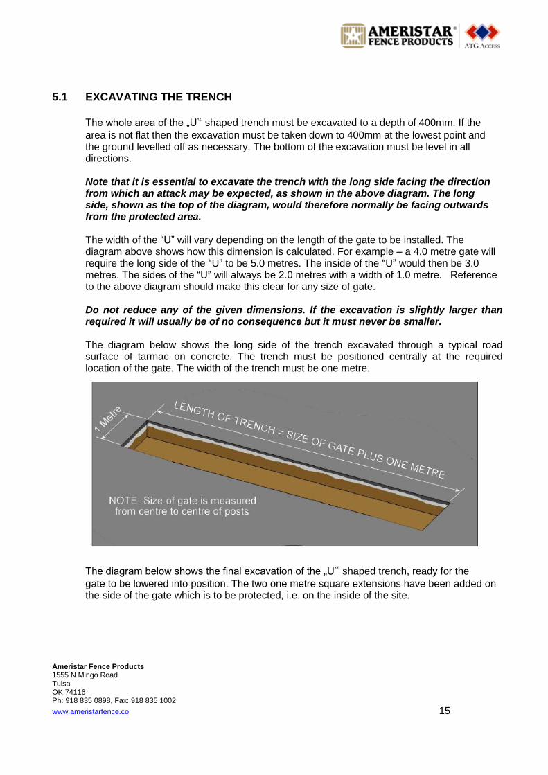
area is not flat then the excavation must be taken down to 400mm at the lowest point and the ground levelled off as necessary. The bottom of the excavation must be level in all directions. Note that it is essential to excavate the trench with the long side facing the direction from which an attack may be expected, as shown in the above diagram. The long side, shown as the top of the diagram, would therefore normally be facing outwards from the protected area. The width of the ―U‖ will vary depending on the length of the gate to be installed. The diagram above shows how this dimension is calculated. For example – a 4.0 metre gate will require the long side of the ―U‖ to be 5.0 metres. The inside of the ―U‖ would then be 3.0 metres. The sides of the ―U‖ will always be 2.0 metres with a width of 1.0 metre. Reference to the above diagram should make this clear for any size of gate. Do not reduce any of the given dimensions. If the excavation is slightly larger than required it will usually be of no consequence but it must never be smaller. The diagram below shows the long side of the trench excavated through a typical road surface of tarmac on concrete. The trench must be positioned centrally at the required location of the gate. The width of the trench must be one metre. The diagram below shows the final excavation of the „U‟ shaped trench, ready for the
gate to be lowered into position. The two one metre square extensions have been added on the side of the gate which is to be protected, i.e. on the inside of the site.

Ameristar Fence Products 1555 N Mingo Road Tulsa OK 74116 Ph: 918 835 0898, Fax: 918 835 1002
www.ameristarfence.co 16
NOTE: that an additional trench is required to install the duct used to carry the hydraulic hoses and low voltage control cables. This must be installed from end of the gate where the locking pin will be located. This is the opposite end to the pivot end of the gate and will depend on whether the gate is right hand or left hand hinged. This trench is not shown in the diagram below.
Having completed the excavation as described above, the complete gate assembly can be lowered into position using suitable lifting tackle. The gate must be placed centrally in the excavation so that there is an equal distance clear all round, nominally 250mm. The diagram below shows a left hand hinged gate located in the excavated trench. The locking end of the gate is therefore on the right as viewed from outside the protected area. The trench for the 100mm duct is shown at the locking end of the gate, (on the left in the diagram). The stub duct can be seen protruding from the end of the frame.

Ameristar Fence Products 1555 N Mingo Road Tulsa OK 74116 Ph: 918 835 0898, Fax: 918 835 1002
www.ameristarfence.co 17
The duct must be connected to the stub provided at the locking pin end. A 100mm diameter flexible duct must be connected to the stub using a Bondseal or similar to make a good connection. The duct must be laid in the trench from the gate to an interrupter pit. The interrupter pit must be located within 3.0 metres from the locking end of the gate. The gate is supplied with two 4.0 metre lengths of ¼ inch hose which must be extended within the interrupter pit with additional hose of sufficient length to reach the control panel position. For distances up to 30 metres ¼ inch hose is adequate. For distances beyond 30 metres contact Ameristar for advice.
It is essential to ensure that there are no sharp bends along any part of the duct run. The absolute minimum allowable angle for any bend is 90º. The total number of bends must be kept to the absolute minimum. Where changes of direction are unavoidable consideration should be given to the installation of further interrupter pits otherwise it might not be possible to pull the hoses through the ducts.
Having installed the ducts it is essential to also install strong draw cords to facilitate the pulling through of the hydraulic hoses and control cables. Both ends of each cord should be
retained by a suitable ―tie-off” to prevent the cords being pulled into the duct and lost.

Ameristar Fence Products 1555 N Mingo Road Tulsa OK 74116 Ph: 918 835 0898, Fax: 918 835 1002
www.ameristarfence.co 18
5.2 CONCRETE FILLING Having completed the installation of the interrupter pit(s) and the ducts the excavation must be filled with C35 concrete to the required level. The diagram below shows the concrete poured level with top of the frame, (this should be a depth of approximately 300mm). The trench for the duct has also been filled to the same level (after installation of the duct).
If the concrete is to be brought up to ground level then it must be poured to a level of approximately 400mm which should bring it to a level of 10mm below the bottom of the ascetic sleeve on the hinge end of the gate. The diagram on the right shows the critical dimensions at the hinge end of the gate. If the area is to be finished with blocks, paving slabs or tarmac etcetera then the concrete should be poured to a level of approximately 300mm which should bring it level with the top of the shallow mount frame. If it does not then sufficient concrete MUST be poured to ensure that it does reach the top of the frame. This leaves a depth of approximately 100mm in which to install the required final finishing surface. This is shown in the diagram above. In both instances the finished level MUST leave a gap of 10mm between the road surface and the bottom of the ascetic sleeve at the hinge end of the gate. This gap is required to ensure that the gate is free to turn and does not foul the road surface.

Ameristar Fence Products 1555 N Mingo Road Tulsa OK 74116 Ph: 918 835 0898, Fax: 918 835 1002
www.ameristarfence.co 19
If adjustment is required to achieve the 10mm gap a section of the ascetic sleeve at the bottom can be removed by careful use of a disc cutter or suitable saw. A masking ring is supplied with the gate which can be used to blank off this adjustment and preserve the appearance of the gate.
5.3 INSTALLING HOSES AND CONTROL CABLES In addition to the two hydraulic hoses, the duct will carry the control cables for connection to the optical position sensors fitted to the locking pin mechanism. 40 metres of cable is provided with the gate, already connected to the two optical sensors in the locking pin post. This should be fed through the duct, together with the two hydraulic hoses, and along the extension duct from the interrupter pit to the control panel position. These cables can be extended if required but in that case must be joined by a suitable waterproof jointing method within an interrupter pit. On no account must hose or cable joins be located within the duct run. If this is done then future maintenance and consequent operation of the gate locking pin will be compromised. The diagram below shows a typical gate with the duct installed at the locking pin end and the concrete poured to a depth of approximately 400mm, i.e. up to the finished road surface.

Ameristar Fence Products 1555 N Mingo Road Tulsa OK 74116 Ph: 918 835 0898, Fax: 918 835 1002
www.ameristarfence.co 20
5.4 LIFTING A SHALLOW MOUNT CITY SCAPE GATE INCLUDING THE FOUNDATION
1. Using an overhead crane, attach a chain lift with four chains
and hooks.
2. Hook each hook into holes at each end of the base.
3. Make sure that that the same corresponding hole is used in
each end of the base
and each side of the
base.
4. You may need to adjust the chain length to
make sure the tension will be the same on all 4
points at the same time to create an even lift.
5. Insert a spacer bar overt the top of the gate in each
side of the chains to make sure the chains are not
touching the gate beam (This will stop scratching and
crushing of the actual gate)
6. Make sure you lift the gate slowly and evenly,
checking the chains are not touching/crushing the
gate as you lift, and that the spacer bars are not
moving and that the hooks are firmly in place in
base.

Ameristar Fence Products 1555 N Mingo Road Tulsa OK 74116 Ph: 918 835 0898, Fax: 918 835 1002
www.ameristarfence.co 21
6 CONTROL PANEL 6.1 GENERAL The controls for the Cityscape gate are supplied in a wall mounting cabinet to which a mains supply must be connected. The photograph on the right shows a typical cabinet of the type supplied. A single phase 230 volt AC electrical supply is required to power the hydraulic pump and electronic control board which control the gate locking pin. The mains supply should be fused at 13 amps. The hydraulic hoses and control cables from the gate are also connected within the panel. Access to the panel interior is via a single lockable hinged door.
6.2 MAINS ISOLATION Mains isolation is by means of a single phase miniature circuit breaker, MCB, housed within the panel. The MCB is an RCD type for complete electrical safety.
It is essential that the single phase MCB is switched OFF before working on equipment within the control panel. Failure to do so could result in electric shock, injury or death.
The photograph on the right shows a typical single phase MCB of the type provided.
Tampering with the equipment by untrained staff may adversely affect the performance of the system and could result in malfunction or unsafe operation.
6.3 CONTROL EQUIPMENT Contained within the control panel are the hydraulic power pack, which drives the locking pin up and down to lock and unlock the gate, and the control components which are used to switch the hydraulic pump on and off. The standard control configuration comprises of the incoming mains isolator mcb, a main controller PCB and a small interface PCB, to which are connected the control cables from the two optical position sensors for the locking pin.

Ameristar Fence Products 1555 N Mingo Road Tulsa OK 74116 Ph: 918 835 0898, Fax: 918 835 1002
www.ameristarfence.co 22
6.3.1 Hydraulic Power Unit A single phase reversing motor drives the hydraulic pump which is controlled by the main control PCB to drive the piston in the hydraulic ram fitted to the locking pin. The control system thus directs hydraulic fluid to one side of the piston or the other in order to raise or lower the locking pin. A hydraulic power pack of the type installed is shown in the photograph on the right. 6.3.2 Oil Tank A small oil tank is fitted to the power pack and this contains sufficient reserve of oil to ensure correct operation. The oil level should be checked weekly or immediately if oil loss is suspected. The oil level should be checked with the locking pin in the unlocked, (fully lowered), position and topped up until the level is just below the threaded portion of the filler cap. NOTE: that the level in the tank will fall when the locking pin is raised as some of the oil will be transferred to the operating ram. The photograph on the right shows an empty tank. The small screw cap with a red insert can be removed for topping up. Alternatively the complete lid can be unscrewed for easier topping up. Do not overfill the tank as this will result in excess oil spilling into the control panel. Any spillage should be mopped up immediately and oil removed from the tank until the correct level is reached. 6.3.3 Manual Lower Lever A manual override lever is fitted to the hydraulic power pack.
The lever is located on the bottom right side of the power pack, shown as A in the photograph on the right. To lower the locking pin move the lever forward to the horizontal position, or just beyond, as shown in the photograph below.
The locking pin will sink slowly under its own weight unless there is damage causing it to jam. In this case it might be possible to assist the downward motion by a small amount of pressure on the top of the pin.

Ameristar Fence Products 1555 N Mingo Road Tulsa OK 74116 Ph: 918 835 0898, Fax: 918 835 1002
www.ameristarfence.co 23
Care should be taken while doing this as excess pressure will return oil very quickly into the tank and this may be spilled into the control panel and on to control components. To return the power unit to normal operation lift the lever to the upright position until resistance is felt. Do not over-tighten the lever.
7 TO LOCK AND UNLOCK THE GATE 7.1 PUSH BUTTON CONTROL The standard gate control package includes a three way control unit as shown in the photograph on the right. To make the unit active it is necessary to insert the key provided into the key switch labelled
―ACTIVATE‖ and then turn the key to the right. This ―arms” the two
push buttons and allows the operator to unlock and lock the gate. By turning the key switch to the left and removing the key, unauthorised use of the push buttons is prevented.
Opening or closing the gate is a two person operation. One person must be stationed at the gate position and the other must be at of the control unit location. The two operators must be in Communication by radio or telephone. NOTE: that the onus is on the operator at the control unit to ensure that it is safe to raise or lower the locking pin before doing so.
7.2 TO OPEN THE GATE Proceed as follows: 1. Insert the key into the ACTIVATE key switch. 2. Turn the key clockwise and leave it in that position. 3. Press the green UNLOCK push button. 4. The locking pin will be hydraulically driven downwards towards the unlocked position. 5. When the locking pin has reached the fully lowered, unlocked, position the gate is free to move. 6. The gate can now be manually opened by the operator at the gate location.
When the gate has reached the fully open position it must be held in place to prevent it moving into the path of vehicles proceeding through the gate. Failure to do this may result in damage to the gate or a serious accident.
The photograph on the below shows the locking pin in the lowered position with the gate open.
Ameristar Fence Products 1555 N Mingo Road Tulsa OK 74116 Ph: 918 835 0898, Fax: 918 835 1002
www.ameristarfence.co 24
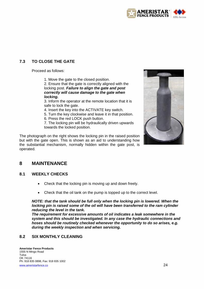
7.3 TO CLOSE THE GATE Proceed as follows: 1. Move the gate to the closed position. 2. Ensure that the gate is correctly aligned with the locking post. Failure to align the gate and post correctly will cause damage to the gate when locking. 3. Inform the operator at the remote location that it is safe to lock the gate. 4. Insert the key into the ACTIVATE key switch. 5. Turn the key clockwise and leave it in that position. 6. Press the red LOCK push button. 7. The locking pin will be hydraulically driven upwards towards the locked position. The photograph on the right shows the locking pin in the raised position but with the gate open. This is shown as an aid to understanding how the substantial mechanism, normally hidden within the gate post, is operated.
8 MAINTENANCE 8.1 WEEKLY CHECKS
Check that the locking pin is moving up and down freely.
Check that the oil tank on the pump is topped up to the correct level. NOTE: that the tank should be full only when the locking pin is lowered. When the locking pin is raised some of the oil will have been transferred to the ram cylinder reducing the level in the tank. The requirement for excessive amounts of oil indicates a leak somewhere in the system and this should be investigated. In any case the hydraulic connections and hoses should be routinely checked whenever the opportunity to do so arises, e.g. during the weekly inspection and when servicing.
8.2 SIX MONTHLY CLEANING
Ameristar Fence Products 1555 N Mingo Road Tulsa OK 74116 Ph: 918 835 0898, Fax: 918 835 1002
www.ameristarfence.co 25
The cartridge must be fully removed in order for adequate cleaning to take place. The instructions in this document detailing how to remove and replace the cartridge must be strictly adhered to.
With the cartridge removed, the inside of the housing should be inspected and any debris should be removed.
The preferred method of cleaning the casing is to remove any debris by hand using a long handled scoop or other suitable tool. The use of a water pressure jet for this task is not recommended.
Before replacing the cartridge in the casing the hydraulic and electrical connections should be cleaned. The hydraulic connectors on the ends of the fixed pipes should be wiped clean to remove any water or dirt. This will ensure that a good connection will be made when the hoses are re-connected and that corrosion is minimised.
The cartridge should not be replaced if there are more than a few millimetres of water in the bottom of the casing. The bottom of the casing should be made as dry as possible.
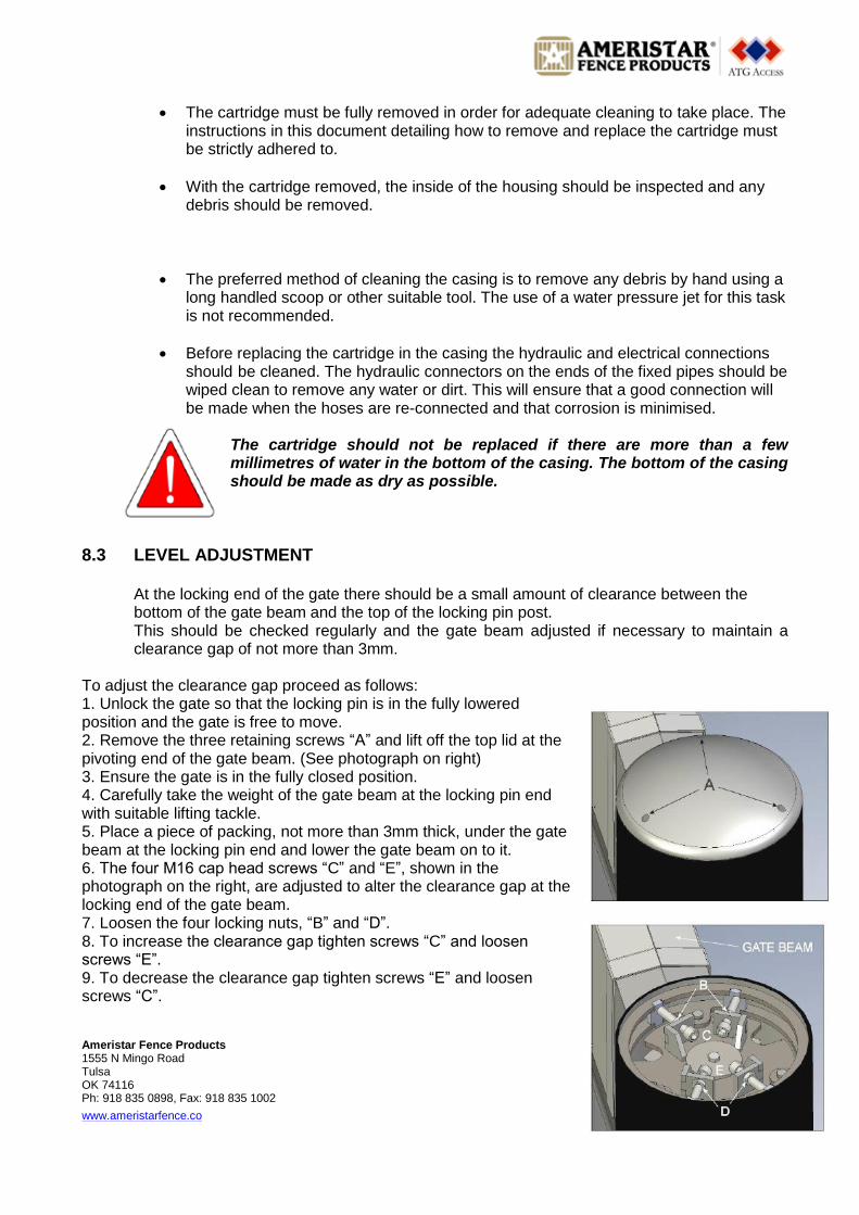
8.3 LEVEL ADJUSTMENT At the locking end of the gate there should be a small amount of clearance between the bottom of the gate beam and the top of the locking pin post. This should be checked regularly and the gate beam adjusted if necessary to maintain a clearance gap of not more than 3mm. To adjust the clearance gap proceed as follows: 1. Unlock the gate so that the locking pin is in the fully lowered position and the gate is free to move. 2. Remove the three retaining screws ―A‖ and lift off the top lid at the pivoting end of the gate beam. (See photograph on right) 3. Ensure the gate is in the fully closed position. 4. Carefully take the weight of the gate beam at the locking pin end with suitable lifting tackle. 5. Place a piece of packing, not more than 3mm thick, under the gate beam at the locking pin end and lower the gate beam on to it. 6. The four M16 cap head screws ―C‖ and ―E‖, shown in the photograph on the right, are adjusted to alter the clearance gap at the locking end of the gate beam. 7. Loosen the four locking nuts, ―B‖ and ―D‖. 8. To increase the clearance gap tighten screws ―C‖ and loosen screws ―E‖. 9. To decrease the clearance gap tighten screws ―E‖ and loosen screws ―C‖.

Ameristar Fence Products 1555 N Mingo Road Tulsa OK 74116 Ph: 918 835 0898, Fax: 918 835 1002
www.ameristarfence.co 26
Do not use the screws to actually lift and lower the gate beam. Use only sufficient tightness against the vertical metal plates to hold the beam in the required position while the packing is in place. 10. Re-tighten the four locking nuts, ―C‖ and ―E‖ 11. Release the gate beam from the lifting tackle and allow it to settle back into position. 12. Check the clearance under the gate beam at the locking pin end and repeat the above procedure if necessary so that the gate swings freely with a gap of no more than 3mm.
8.4 LOCKING PIN POSITION SENSING The position of the locking pin is detected by two photocells located within the cartridge of the hydraulic operator. One photocell detects when the locking pin is in the fully raised position. The other photocell detects when the locking pin is in the fully lowered position. In the diagram on the right the two photocell viewing locations are shown as red triangles. If a photocell fault occurs it will be necessary to remove the hydraulic cartridge in order to clean or replace the photocell. The photograph at bottom right shows the type of photocell fitted. For reference the Ameristar part number for the photocell is 15652. A special connecting lead is also used and must be replaced if necessary with the correct Ameristar part number 15653.
To gain access to the photocells.
In order to gain access to the photocells it is necessary to remove the complete hydraulic cartridge from within the outer casing. This is a two stage process which requires lifting gear. The process is as follows: 1. Remove the Flange and Sleeve 2. Remove Cartridge These procedures are described in the following pages. 8.5 TO REMOVE THE FLANGE AND SLEEVE
The sleeve is very heavy and weighs in excess of 50kg. It must be lifted with appropriate lifting equipment.
Proceed as follows:

Ameristar Fence Products 1555 N Mingo Road Tulsa OK 74116 Ph: 918 835 0898, Fax: 918 835 1002
www.ameristarfence.co 27
1. Remove the 6 countersunk screws that secure the flange and sleeve. 2. Lift off the flange 3. Screw two M12 lifting eyes into the sleeve. 4. Feed a short spreader bar through the two eyes and secure with nuts to prevent it sliding out 5. Lift the sleeve clear of the fixed post casing using the lifting equipment
8.6 TO REMOVE THE CARTRIDGE This item is very heavy and must be lifted with appropriate lifting equipment. A special lifting bar must be used which is shown in the photograph on the right.
The lifting bar is secured to the top of the slide tube by two bolts. A sling can then be passed through the ring so that the weight can be supported by suitable lifting equipment. 1. Remove the six countersunk M16 bolts. 2. Remove the stainless steel disk. 3. Attach the lifting frame using two bolts. 4. Locate and open the chamber that contains the slack for the hoses and cables. 5. Lift the cartridge clear of the fixed post tube using the lifting equipment taking care not to damage the cables. It will be necessary to feed some slack for the hoses and cables.
8.7 TO REFIT THE CARTRIDGE 1. Lower the cartridge into the fixed post keeping the hoses tight and taking care to avoid cable damage. 2. Fit the stainless steel disk. 3. Refit the six countersunk M16 bolts. 4. Remove the lifting frame.
8.8 TO REFIT THE SLEEVE 1. Lift the Sleeve using the lifting equipment as described for removal in this section of the document. 2. Lower the sleeve carefully into the fixed post. 3. Fit the stainless steel flange. 4. Refit the six countersunk screws.

Ameristar Fence Products 1555 N Mingo Road Tulsa OK 74116 Ph: 918 835 0898, Fax: 918 835 1002
www.ameristarfence.co 28
9 SERVICE Warranty Period The warranty period runs for twelve months from the date that the system was handed over. This date is shown on the Completion Certificate which is filled in and signed as part of the gate hand-over procedure. The Completion Certificate is signed by a representative of the customer and by the ATG engineer who demonstrated the operation of the system on that day. NOTE: Ameristar Service Department will respond as quickly as possible to requests for service but the warranty does not include any implied nor actual priority over other requests for service or commitments to our contract customers.
IMPORTANT: The warranty period should not be considered as a maintenance free time as, like any mechanical device, routine servicing is essential to ensure satisfactory and safe operation following hand-over of the system to the customer.
A Service Contract is strongly recommended starting from the date of hand-over, (see below), but if this is not taken up then a minimum of one service every six months must be carried out. Failure to do this may invalidate the warranty on one or more parts and result in charges for the replacement parts plus travelling and site time.
Response Time Under the terms of Ameristar Service Contracts priority must be given to those customers who have a current valid contract in place. This could result, during busy periods, in a delay of several days between receipt of the service request and an engineer becoming available to go to site. This is a worst case situation and Ameristar Service Department will always do their best to respond as quickly as possible to a customers needs.
Service Contracts Ameristar offer a range of comprehensive Service Contracts to suit customer requirements and it is recommended that one of these is taken up to ensure continuing satisfactory and safe operation of the gate, both during and following the warranty period. Service contracts are available which include parts and labour. Next working day response can also be included for those systems where down time must be kept to a minimum. A Service Contract Enquiry form is included with this document which can be filled in and sent by fax or post to Ameristar if a contract is not already in place.
Service during warranty period It is important to understand that the warranty covers parts and labour only where the gate is non-operational due to a failed part supplied by Ameristar and then only when the recommended servicing has been carried out during the warranty period. (See also IMPORTANT note above).

Ameristar Fence Products 1555 N Mingo Road Tulsa OK 74116 Ph: 918 835 0898, Fax: 918 835 1002
www.ameristarfence.co 29
Parts and labour required for repairs following a failure of the gate caused by, for example, vehicle impact, vandalism or failure to have the recommended warranty period service carried out will be chargeable. The above may not be applicable if a Service Contract is put in place within the warranty period.
Service outside warranty period Following expiry of the warranty period all parts and labour become chargeable, except where they are covered by an applicable Service Contract.
Requests for Service All requests for service, even within the warranty period, must be received in writing by ATG Service Department before a service engineer call can be logged and a time allocated. A telephone call alone will not enable Ameristar to allocate resources to a request for service and a call must always be followed up in writing or by fax. An official order number must also be given, even if the equipment is still under warranty. A ―Request for Service‖ form is included in this document which can be filled in and sent by fax to Ameristar Service Department. This form includes the essential information needed in order to process the request with the minimum delay. The form may be removed from the document and photocopied as many times as necessary.
10 APPENDIX A: AEROSHELL FLUID 41 The information contained herein has been extracted from Safety Data Sheet number 001A0050 dated 11/11/04 published by Shell UK Products Limited. It is included as a guide only for the purpose of health, safety and environmental requirements and should not be taken as conclusive.
Hazards Identification EC Classification Not classified as Dangerous under EC criteria Human Health Hazards No specific hazards under normal use conditions. Prolonged or repeated exposure may give rise to dermatitis. Used oil may contain harmful impurities. Safety Hazards Not classified as flammable, but will burn. Environmental Hazards Not classified as dangerous for the environment.
Ameristar Fence Products 1555 N Mingo Road Tulsa OK 74116 Ph: 918 835 0898, Fax: 918 835 1002
www.ameristarfence.co 30
First Aid Measures Not expected to give rise to an acute hazard under normal conditions of use. Inhalation In the unlikely event of dizziness or nausea, remove casualty to fresh air. If symptoms persist obtain medical advice. Skin Remove contaminated clothing and wash affected skin with soap and water. If persistent irritation occurs obtain medical attention. If high pressure injection injuries occur obtain medical attention immediately. Eyes Flush affected eyes with copious quantities of water. If persistent irritation occurs obtain medical attention. Ingestion Wash out the mouth with water and obtain medical attention. Do not induce vomiting.
Advice to Doctor Treat symptomatically. Aspiration into the lungs may cause chemical pneumonitis. Dermatitis may result from prolonged or repeated exposure. High pressure injection injuries require surgical intervention and possibly steroid therapy to minimise tissue damage and loss of function Because entry wounds are small and do not reflect the seriousness of the underlying damage, surgical exploration to determine the extent of involvement may be necessary. Local anaesthetics or hot soaks should be avoided because they can contribute to swelling, vasospasm and ischaemia. Prompt surgical decompression, debridement and evacuation of foreign material should be performed under general anaesthetics, and wide exploration is essential. There may be a risk to health where low viscosity products are aspirated into the lungs following vomiting, although this is uncommon in adults. Such aspiration would cause intense local irritation and chemical pneumonitis. Children, and those in whom consciousness is impaired, will be more at risk. Emesis of lubricants is not usually necessary, unless a large amount has been ingested, or some other compound has been dissolved in the product. If this is indicated, for example, when there is rapid onset of central nervous system depression from large ingested volume, gastric lavage under controlled hospital conditions, with full protection of the airway is required. Supportive care may include oxygen, arterial blood gas monitoring, respiratory support, and, if aspiration has occurred, treatment with corticosteroids and antibiotics. Seizures should be controlled with Diazepam, or appropriate equivalent drug.

Ameristar Fence Products 1555 N Mingo Road Tulsa OK 74116 Ph: 918 835 0898, Fax: 918 835 1002
www.ameristarfence.co 31
Fire Fighting Measures Combustion is likely to give rise to a complex mixture of airborne solid and liquid particulates and gases, including carbon monoxide and unidentified organic and inorganic compounds. Foam and dry chemical powder, carbon dioxide, sand or earth may be used for small fires only. Do not use jets of water. Use of halon extinguishers should be avoided for environmental reasons. Suitable protective equipment including breathing apparatus must be worn when approaching a fire in a confined space.
Accidental Release Measures Avoid contact with skin and eyes. Wear PVC, Neoprene or nitrile rubber gloves. Wear rubber knee length safety boots, PVC jacket and trousers. Wear safety glasses if splashes are likely to occur. Prevent from spreading or entering drains, ditches or rivers by using sand, earth or other appropriate barriers. Inform the local authorities if this cannot be prevented. Absorb liquid with sand or earth. Sweep up and remove to a suitable, clearly marked container for disposal in accordance with local regulations.
Handling and Storage Handling Use local exhaust ventilation if there is a risk of inhalation of vapours, mists or aerosols. Avoid prolonged or repeated contact with skin. When handling product in drums safety footwear should be worn and suitable handling equipment should be used. Prevent spillages. Cloth, paper and other materials that are used to absorb spills present a fire hazard. Avoid their accumulation by disposing of them safely and immediately. In addition to any specific recommendations given for controls of risks to health, safety and the environment, an assessment of risks must be made to help determine controls appropriate to local circumstances. Exposure to this product should be reduced as low as reasonably practicable. Reference should be made to the Health and Safety Executive publication ―COSHH Essentials‖. Storage Keep in a cool, dry, well ventilated place. Use properly labelled and closeable containers. Avoid direct sunlight, heat sources and strong oxidising agents. The storage of this product may be subject to the Control of Pollution (Oil Storage) (England) Regulations. Further guidance may be obtained from the local Environmental Agency office. Storage temperature should be between 0C minimum and 50C maximum. For containers or container linings use mild steel or high density polyethylene. PVC should be avoided. Polyethylene containers should not be exposed to high temperatures because of possible risk of distortion.

Ameristar Fence Products 1555 N Mingo Road Tulsa OK 74116 Ph: 918 835 0898, Fax: 918 835 1002
www.ameristarfence.co 32
Exposure Controls The use of personal protective equipment is only one aspect of an integrated approach to the Control of Substances Hazardous to Health. The management of Health and Safety at Work Regulations 1992 require employers to identify and evaluate the risks to health and to implement appropriate measures to eliminate or minimise those risks. The choice of personal protective equipment is highly dependent upon local conditions, e.g. exposure to other chemical substances and micro-
organisms, thermal hazards (protection from extremes of cold and heat), electrical hazards, mechanical hazards and appropriate degree of manual dexterity required to undertake an activity Whilst the content of this section may inform the choice of personal protective equipment used, the limitations of any information which can be provided must be fully understood, e.g. personal protective equipment chosen to protect employees from occasional splashes may be entirely inadequate for activities involving partial or complete immersion. If the levels of oil mist or vapour in air are likely to exceed the occupational exposure standards, then consideration should be given to the use of local exhaust ventilation to reduce personal exposure. The choice of personal protective equipment should only be undertaken in the light of a full risk assessment by a suitably qualified competent person (e.g. a professionally qualified occupational hygienist). Effective protection is only achieved by correctly fitting and well maintained equipment and employers should ensure that appropriate training is given. All personal protective equipment should be regularly inspected and replaced if defective.
Reference should be made to HSE‟s publication Methods for the Determination of
Hazardous Substances (MDHS) 84 – Measurement of oil mist from mineral oil-based metalworking fluids. Measurement of an employee’s exposure to oil vapour may be supplemented through the
use of stain tubes. In the first instance, further guidance may be obtained through HSE’s
publication ―COSHH – a brief guide to the regulations‖ (INDG 136(rev 1)).
Respiratory Protection At standard temperature and pressure, the Occupational Exposure Standard for oil vapour is unlikely to be exceeded. Care should be taken to keep exposures below applicable occupational exposure limits. In the unlikely event that this cannot be achieved use of a respirator fitted with an organic vapour cartridge combined with a particulate pre-filter should be considered. If product is subjected to elevated temperatures, half masks (EN 149) or valved half masks (EN 405) in combination with type AX (EN 371) and P2/3 (EN 143) pre-filters maybe considered.
Hand Protection Chemical protective gloves are made from a wide range of materials, but there is not a single glove material, (or combination of materials), which gives unlimited resistance to any individual or combination of substances or preparations. The extent of the breakthrough time will be affected by a combination of factors which include permeation, penetration, degradation, use pattern (full immersion, occasional contacts) and how the glove is stored when not in use. Theoretical maximum levels of protection are seldom achieved in practice and the actual level of protection can be difficult to assess. Effective breakthrough time should be used with care and a margin of safety should be applied. HSE guidance on protective gloves

Ameristar Fence Products 1555 N Mingo Road Tulsa OK 74116 Ph: 918 835 0898, Fax: 918 835 1002
www.ameristarfence.co 33
recommends a 75% safety factor be applied to any figures obtained in a laboratory test. Nitrile gloves may offer relatively long breakthrough times and slow permeation rates. Test data, e.g. breakthrough data obtained through test standard EN 374-3:1994, are available from reputable equipment suppliers. Personal hygiene is a key element of effective hand care. Gloves must only be worn on clean hands. After using gloves, hands should be washed and dried thoroughly. A non perfumed moisturiser should be applied.
Eye Protection Goggles conforming to a minimum standard of EN 166 345B should be considered if there is a possibility of eye contact with the product through splashing. Higher rated eye protection must be considered for highly hazardous operations or work areas.
Body Protection Minimise all forms of skin contact. Overalls and shoes with oil resistant soles should be worn. Launder overalls and undergarments regularly.
Environmental Exposure Controls Minimise release to the environment. An environmental assessment must be made to ensure compliance with local environmental legislation.
Ecological Information This information is based on knowledge of the product components and the ecotoxicology of similar products. The product is liquid under most environmental conditions and will float on water. Product is not expected to be readily biodegradable. Major constituents are expected to be inherently biodegradable but the product contains components that may persist in the environment. Also contains components with the potential to bioaccumulate. Product is a poorly soluble mixture. It may cause physical fouling of aquatic organisms but is expected to be practically non-toxic to them. Chronic effects to aquatic organisms are not expected at concentrations less than 1 mg/l. Not expected to have ozone depletion potential, photochemical ozone potential or global warming potential. Product is a mixture of non-volatile components which are not expected to be released into the air in any significant quantities.
Waste, Product and Container Disposal Recycle or dispose of the product with an authorised contractor in accordance with prevailing regulations. Do not pollute the soil, water or environment with the product.

Ameristar Fence Products 1555 N Mingo Road Tulsa OK 74116 Ph: 918 835 0898, Fax: 918 835 1002
www.ameristarfence.co 34


![Decision and Order [Redacted Public Version] · operations, properties, and services related thereto. J. “Ameristar St. Charles” means Respondent Pinnacle’s Ameristar Casino](https://static.fdocuments.net/doc/165x107/5f6c94d03f66bf36f071f49a/decision-and-order-redacted-public-version-operations-properties-and-services.jpg)


![Ameristar Marketing Inc Client Presentation[2011]](https://static.fdocuments.net/doc/165x107/55c0c113bb61eb77328b4673/ameristar-marketing-inc-client-presentation2011.jpg)