America's Wire Company - USA Wire & Cable, Inc. · PDF fileUSA Wire & Cable, Inc. inventories...
94
America’s Wire Company Dear Customer, We’re pleased to provide you with our latest product catalog featuring many cables stocked in our warehouse located in Austin, Texas plus a backup inventory of products available from more than 50 top manufacturers! For more than 27 years USA Wire & Cable, Inc. has been an industry-leading wire and cable distributor for specialty industrial wire and cable. As a master distributor we are very proud of our team of sales managers, which has more than 250 years of combined industry knowledge and experience. USA Wire & Cable, Inc. inventories only America-made wire and cable from top manufacturers, including Okonite, General Cable, Southwire, Service Wire and Nexans, just to name a few. Our inventory is managed by a computerized system that provides our sales staff with instantaneous information down to the precise length of cable footage, description of cable type and the actual location in our multiple warehouses. Thanks to our Cable Management Services, you can rest assured that everything is taken care of upfront for your industrial project needs – from initial planning, specification review, lock-in copper, pre-purchase of bulk material, staging of material indoors, packaging and shipping the material to the jobsite. The cable will arrive on time anywhere in the world – cut to circuit length, labeled and ready for installation! Please take a look at our latest catalog and give us a call at 800-880-9473 today for your industrial wire and cable needs. We appreciate your business! Sincerely, Joe Navarro President 6301 E. Stassney Ln. Bldg. 6 Ste. 200 Austin, TX 78744 TOLL FREE 800‐880‐9473 OFFICE 512‐443‐9473 FAX 512‐443‐6329
Transcript of America's Wire Company - USA Wire & Cable, Inc. · PDF fileUSA Wire & Cable, Inc. inventories...
America’s Wire Company
Dear Customer,
We’re pleased to provide you with our latest product catalog featuring many cables stocked in our warehouse located in Austin, Texas plus a backup inventory of products available from more than 50 top manufacturers!
For more than 27 years USA Wire & Cable, Inc. has been an industry-leading wire and cable distributor for specialty industrial wire and cable. As a master distributor we are very proud of our team of sales managers, which has more than 250 years of combined industry knowledge and experience.
USA Wire & Cable, Inc. inventories only America-made wire and cable from top manufacturers, including Okonite, General Cable, Southwire, Service Wire and Nexans, just to name a few. Our inventory is managed by a computerized system that provides our sales staff with instantaneous information down to the precise length of cable footage, description of cable type and the actual location in our multiple warehouses.
Thanks to our Cable Management Services, you can rest assured that everything is taken care of upfront for your industrial project needs – from initial planning, specification review, lock-in copper, pre-purchase of bulk material, staging of material indoors, packaging and shipping the material to the jobsite. The cable will arrive on time anywhere in the world – cut to circuit length, labeled and ready for installation!
Please take a look at our latest catalog and give us a call at 800-880-9473 today for your industrial wire and cable needs. We appreciate your business!
Sincerely,
Joe Navarro President
6301 E. Stassney Ln. Bldg. 6 Ste. 200 Austin, TX 78744 TOLL FREE 800‐880‐9473 OFFICE 512‐443‐9473 FAX 512‐443‐6329

TABLE of CONTENTS
Section
1 Cable Management 2 Bare Copper 3 600V Single Conductor
THW, XHHW, USE, RHW, RHH, CP
4 Control & Tray Cable 20-10, VNTC, XLP-PVC, XL-CPE, FREP-CPE, LSZH
5 Instrumentation PLTC (OS, SPOS, STOS), Nylon-PVC TC (OS, SPOS, STOS), FREP-CPE (OS, SPOS, STOS), LSZH (OS, SPOS, STOS), Thermocouple Cable PVC, XLPE (POS, SPOS)
6 Portable DLO, Type W, Type G, Type G-GC, Welding Cable, SOOW, Stage Lighting, Exciter Cable
7 Medium Voltage Power EPR-PVC (5-8-15-35kV)
8 Interlocked Armored Cable Control Sizes, 3 and 4C (600V), EPR (5-8-15kV)
9 MC-HL OS/SPOS/STOS, Control Sizes, 3 and 4C (600V), EPR (5-8-15kV)
10 Technical Data 11 Wire Knowledge
The information contained in this catalog is derived from many sources, including numerous third-party manufacturers and suppliers. No effort has been made to independently verify the accuracy of such information. USA Wire & Cable, Inc. (USAWC) does not warrant or assume responsibility in any manner for the accuracy of the descriptions, pictures, dimensions, weights or characteristics of the information contained herein. All such information is subject to change from time and time, and USAWC assumes no responsibility for revising this catalog to reflect such changes. Accordingly, the availability and suitability of specific products for their intended purposes should be confirmed at the time or order, and the conformity of all products to order specifications should be verified at the time of delivery.

America’s Wire Company
Cable Management Services As a master distributor of American-made specialty wire and cable, USA Wire & Cable is uniquely qualified to handle any industrial products you or your customers may have involving instrumentation, thermocouple, control tray, power tray, single conductor, power, MC-HL armored and MV-105 power cable.
A large portion of our service for project support normally includes some level of Cable Management. A Cable Management Program can vary in scope from a simple logistics package to a highly integrated bundle of services.
USA Wire & Cable defines in detail each possible component that can be combined to tailor a custom package for any project your customers may have. Our package may contain any or all of the following:
• Lock-in copper – Uncertainty of copper fluctuations can be firmed on day of order.
• Specification clarification and interpretation – We have many years of experience in the technical evaluation and formation of wire and cable specifications. Since we represent a wide range of manufacturers, we can offer unbiased assistance to make sure your specifications are up to date and that the materials furnished meet or exceed your customers’ expectations. In addition, we can assist with value-added engineering with a selection of alternative constructions to decrease overall project costs.
• Prepurchase of bulk wire and cable for project needs – Under contract we can acquire all cable items needed for a particular project, insuring that delivery schedules can be met with no guesswork. Cable requirement changes can be accomplished seamlessly throughout the project. In most cable management scenarios, cable is not invoiced to you or your customer until it is released to the job site.
• Storage – Cable is stored indoors at our facility, at the job site or near the job site as project requirements dictate.
• Packaging – Cable can be released in bulk reels to the job site when specific lengths are not available or, if individual pull requirements are known, cable can be cut to circuit length, wrapped and tagged with circuit and all applicable identifying information. USA Wire & Cable packaging standards are the best in the industry. Your cable arrives at the job site consistently damage free and ready to use, minimizing freight claims and costly reissuing of releases and scheduling of field resources.
• Shipping – Your releases are normally shipped via 53-ft. enclosed trucks on LTL or FTL carriers. Upon special request large reels of cable can be shipped in an upright rolling position on a flatbed trailer for easy unloading at the job site. Your cable arrives free of damage and ready to use. Releases ship within 24-48 hours anywhere in the United States.
• Documentation and reporting – Throughout the project term we keep you informed with detailed, up-to-the-minute analysis of the cable package in place for your job. By monitoring the cable down to each specific reel, waste can be minimized and usage trends can be identified so that a continuous flow of product is assured throughout the life of your project.
• End-of-project disposal – At project’s end the remaining product in appropriate lengths can be retained in our inventory with pre-agreed-upon restocking terms. This service eliminates the common practice of job-end random sale or scrapping of leftover cable.
In addition to the above menu of services, USA Wire & Cable can perform any requested task to make your project’s wire and cable requirements flow smoothly.
Industries served: Coal-fired ● Solar ● Natural Gas-fired ● Renewable Energy ● Petrochemical ● Oil & Gas Refining ● Air Quality Control ● Transmission & Distribution ● Chemical Manufacturing
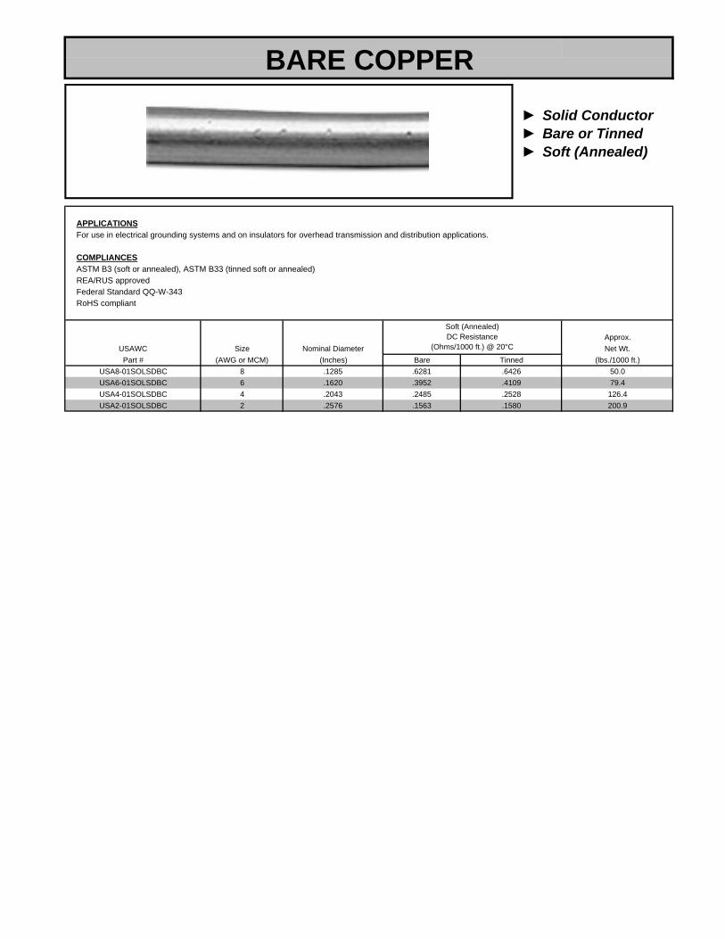
► Solid Conductor► Bare or Tinned► Soft (Annealed)
APPLICATIONSFor use in electrical grounding systems and on insulators for overhead transmission and distribution applications.
COMPLIANCESASTM B3 (soft or annealed), ASTM B33 (tinned soft or annealed)REA/RUS approvedFederal Standard QQ-W-343RoHS compliant
Approx.USAWC Size Nominal Diameter Net Wt.Part # (AWG or MCM) (Inches) Bare Tinned (lbs./1000 ft.)
USA8-01SOLSDBC 8 .1285 .6281 .6426 50.0USA6-01SOLSDBC 6 .1620 .3952 .4109 79.4USA4-01SOLSDBC 4 .2043 .2485 .2528 126.4USA2-01SOLSDBC 2 .2576 .1563 .1580 200.9
Soft (Annealed)DC Resistance
(Ohms/1000 ft.) @ 20°C
BARE COPPER

► Stranded Conductor► Bare or Tinned► Soft (Annealed)
APPLICATIONSFor use in electrical grounding systems and on insulators for overhead transmission and distribution applications. Stranded conductors offer greaterflexibility than solid.
COMPLIANCESASTM B3 (soft or annealed), ASTM B8 (concentric lay stranded), ASTM B33 (tinned soft or annealed), ASTM B787 (combination strand)REA/RUS approvedFederal Standard QQ-W-343RoHS compliant
Approx.USAWC Size Strand Nominal Diameter Net Wt.Part # (AWG or MCM) (No.) (Inches) Bare Tinned (lbs./1000 ft.)
USA14-01STRSDBC 14 7 .0726 2.5800 2.6800 12.7USA12-01STRSDBC 12 7 .0915 1.6200 1.6900 20.2USA10-01STRSDBC 10 7 .1160 1.0200 1.0600 32.0USA8-01STRSDBC 8 7 .1460 .6408 .6654 50.9USA6-01STRSDBC 6 7 .1840 .4030 .4196 81.0USA4-01STRSDBC 4 7 .2320 .2540 .2637 128.9USA2-01STRSDBC 2 7 .2920 .1594 .1657 204.9USA1 01STRSDBC 1 19 3320 1265 1313 258 4
Soft DrawnDC Resistance
(Ohms/1000 ft.) @ 20°C
BARE COPPER
USA1-01STRSDBC 1 19 .3320 .1265 .1313 258.4USA1/0-01STRSDBC 1/0 19 .3730 .1003 .1043 325.8USA2/0-01STRSDBC 2/0 19 .4190 .0795 .0826 410.9USA3/0-01STRSDBC 3/0 19 .4700 .0631 .0655 518.1USA4/0-01STRSDBC 4/0 19 .5280 .0500 .0515 653.3USA250-01STRSDBC 250 37 .575 .0423 .0440 771.9USA350-01STRSDBC 350 37 .681 .0302 .0314 1081.0USA500-01STRSDBC 500 37 .813 .0212 .0218 1544.0USA750-01STRSDBC 750 61 .998 .0141 .0145 2316.0USA1000-01STRSDBC 1000 61 1.152 .0106 .0109 3088.0

► Type THW-2► VW-1► 600V
PRODUCT CONSTRUCTIONConductor: Single copper conductor, stranded.Insulation: Resistant to sunlight, moisture, heat and flame.Jacket: Polyvinyl chloride compound. Temperature rating 90°C in wet and dry locations. All sizes pass the vertical flame test (VW-1). Colors available.
APPLICATIONSSuitable for use in conduit or other recognized raceways for services, feeders and branch circuit wiring. Also suitable for general purpose grounding forpower and distribution circuits in residential, industrial and commercial buildings.
COMPLIANCESASTM B3 (soft or annealed), ASTM B8 (concentric lay stranded), ASTM B33UL 83Federal spec A-A-59544, 90°C wet/dryCT use 1/0 and largerOil resistant ISunlight resistant (black only)NEMA WC70/ICEA S-95-658RoHS compliant
NominalInsulation Diameter Approx. Ampacity*
USAWC Size Strand Thickness Overall Net Wt 90°C
SINGLE CONDUCTOR
USAWC Size Strand Thickness Overall Net Wt. 90°CPart # (AWG or MCM) (No.) (Mils) (Inches) (lbs./1000 ft.) Wet/Dry
USA14-01THW-2 14 7 30 .133 19 35†USA12-01THW-2 12 7 30 .152 28 40†USA10-01THW-2 10 7 30 .176 41 55†USA8-01THW-2 8 7 45 .236 68 80USA6-01THW-2 6 7 60 .304 109 105USA4-01THW-2 4 7 60 .352 163 140USA3-01THW-2 3 7 60 .380 199 165USA2-01THW-2 2 7 60 .412 245 190USA1-01THW-2 1 19 80 .481 320 220
USA1/0-01THW-2 1/0 19 80 .520 393 260USA2/0-01THW-2 2/0 19 80 .564 485 300USA3/0-01THW-2 3/0 19 80 .614 599 350USA4/0-01THW-2 4/0 19 80 .670 743 405USA250-01THW-2 250 37 95 .765 893 455USA300-01THW-2 300 37 95 .819 1057 505USA350-01THW-2 350 37 95 .871 1221 570USA400-01THW-2 400 37 95 .918 1384 615USA500-01THW-2 500 37 95 1.003 1708 700USA600-01THW-2 600 61 110 1.113 2062 780USA750-01THW-2 750 61 110 1.218 2547 885
USA1000-01THW-2 1000 61 110 1.372 3351 1055
*Based on ambient temperature of 30°C Per NEC Table 310-17.†Overcurrent protection shall not exceed 15 amps for 14 AWG, 20 amps for 12 AWG and 30 amps for 10 AWG per NEC 310-17 footnote.NOTE: The data shown is approximate and subject to standard industry tolerances.

► XHHW-2► XLP► 600V
PRODUCT CONSTRUCTIONConductor: Single copper conductor, stranded.Insulation: Resistant to moisture, heat and flame.Jacket: Chemically cross-linked polyethylene. Temperature rating 90°C in wet and dry locations. Colors available.
APPLICATIONSSuitable for general purpose wiring, power distribution and branch circuit wiring where a cable with superior flame retardance is required. Also suitable forfor use in low leakage circuits requiring a dielectric constant of 3.5 or less (hospital grade).
COMPLIANCESASTM B3, ASTM B8UL 44, ICEA S-95-658/NEMA WC70Federal spec A-A-59544, 90°C wet/dryCT use 1/0 and largerGasoline and oil resistant IIC(UL)US RW90: CSA/UL listedSunlight resistant-40°C rated, suitable for use in 105°C dry systemRoHS compliant
NominalInsulation Diameter Approx. Ampacity*
SINGLE CONDUCTOR
Insulation Diameter Approx. AmpacityUSAWC Size Strand Thickness Overall Net Wt. 90°CPart # AWG or MCM (No.) (Mils) (Inches) (lbs./1000 ft.) Wet/Dry
USA14-01XHHW-2 14 7 30 .133 17 35†
USA12-01XHHW-2 12 7 30 .152 26 40†
USA10-01XHHW-2 10 7 30 .176 39 55†
USA8-01XHHW-2 8 7 45 .236 63 80USA6-01XHHW-2 6 7 45 .274 96 105USA4-01XHHW-2 4 7 45 .322 147 140USA3-01XHHW-2 3 7 45 .350 182 165USA2-01XHHW-2 2 7 45 .382 226 190USA1-01XHHW-2 1 19 55 .431 287 220
USA1/0-01XHHW-2 1/0 19 55 .470 358 260USA2/0-01XHHW-2 2/0 19 55 .514 446 300USA3/0-01XHHW-2 3/0 19 55 .564 557 350USA4/0-01XHHW-2 4/0 19 55 .620 697 405USA250-01XHHW-2 250 37 65 .705 830 455USA300-01XHHW-2 300 37 65 .759 989 505USA350-01XHHW-2 350 37 65 .811 1148 570USA400-01XHHW-2 400 37 65 .858 1306 615USA500-01XHHW-2 500 37 65 .943 1623 700USA600-01XHHW-2 600 61 80 1.053 1961 780USA750-01XHHW-2 750 61 80 1.158 2435 885
*Per NEC Table 310-17.†Overcurrent protection shall not exceed 15 amps for 14 AWG, 20 amps for 12 AWG and 30 amps for 10 AWG per NEC 310-17 footnote.NOTE: The data shown is approximate and subject to standard industry tolerances.

► XHHW-2► XLP► VW-1► 600V
PRODUCT CONSTRUCTIONConductor: Single copper conductor, stranded.Insulation: Resistant to moisture, heat and flame.Jacket: Chemically cross-linked polyethylene. Temperature rating 90°C in wet and dry locations. All sizes pass the vertical flame test (VW-1). Colors available.
APPLICATIONSSuitable for general purpose wiring, power distribution and branch circuit wiring where a cable with superior flame retardance is required. Also suitable forfor use in low leakage circuits requiring a dielectric constant of 3.5 or less (hospital grade).
COMPLIANCESASTM B3, ASTM B8 (concentric lay stranded), ASTM B787UL 44, ICEA S-95-658/NEMA WC70Federal spec A-A-59544, 90°C wet/dryCT use 1/0 and largerIEEE 1202/FT4Gasoline and oil resistant IIC(UL)US RW90:CSA/UL listedSunlight resistant (#14-#8: black only)-40°C rated, suitable for use in 105°C dry systemRoHS compliant
Nominal
SINGLE CONDUCTOR
NominalInsulation Diameter Approx. Ampacity*
USAWC Size Strand Thickness Overall Net Wt. 90°CPart # (AWG or MCM) (No.) (Mils) (Inches) (lbs./1000 ft.) Wet/Dry
USA14-01XLPVW1 14 7 30 .133 18 35†
USA12-01XLPVW1 12 7 30 .152 27 40†
USA10-01XLPVW1 10 7 30 .176 40 55†
USA8-01XLPVW1 8 7 45 .236 66 80USA6-01XLPVW1 6 7 45 .274 99 105USA4-01XLPVW1 4 7 45 .322 152 140USA3-01XLPVW1 3 7 45 .350 187 165USA2-01XLPVW1 2 7 45 .382 233 190USA1-01XLPVW1 1 19 55 .431 293 220
USA1/0-01XLPVW1 1/0 19 55 .470 364 260USA2/0-01XLPVW1 2/0 19 55 .514 457 300USA3/0-01XLPVW1 3/0 19 55 .564 570 350USA4/0-01XLPVW1 4/0 19 55 .620 710 405USA250-01XLPVW1 250 37 65 .705 848 455USA300-01XLPVW1 300 37 65 .759 1007 500USA350-01XLPVW1 350 37 65 .811 1170 570USA400-01XLPVW1 400 37 65 .858 1327 615USA500-01XLPVW1 500 37 65 .943 1648 700USA600-01XLPVW1 600 61 80 1.053 1991 780USA750-01XLPVW1 750 61 80 1.158 2469 885
*Per NEC Table 310-17.†Overcurrent protection shall not exceed 15 amps for 14 AWG, 20 amps for 12 AWG and 30 amps for 10 AWG per NEC 310-17 footnote.NOTE: The data shown is approximate and subject to standard industry tolerances.

► USE-2► RHH or RHW-2► 600V
PRODUCT CONSTRUCTIONConductor: Single, stranded copperInsulation: Moisture-, heat- and flame-resistant, chemically cross-linked polyethylene insulation. All sizes pass the vertical flame test(VW-1). Temperature rating 90°C in wet and dry locations. Available in colors.
APPLICATIONSFor use in general purpose wiring applications. May be installed in conduit, raceway, aerial and direct burial installation where a cable with superiorflame retardance is required. Also suitable for use in low leakage circuits requiring a dielectric constant of 3.5 or less (hospital grade).
COMPLIANCESASTM B3, B8, B787. Listed by UL as Type XHHW-2 per Standard 44. Listed by UL as Gasoline and Oil Resistant II. UL Direct Burial. Cables are UL listed as Sunlight Resistant (14-8AWG, black only). For CT use/IEEE 1202/FT4 size 1/0 AWG and larger. C(UL) RPV90 600V. C(UL) US RW90 1kV:CSA/UL Listed. UL 44 and UL 854,ICEA S-95-658/NEMA WC70, Federal spec. A-A-59544. -40°C rated. Suitable for use in 105°C dry system. RoHS compliant.
Insulation Nom.USAWC Size No. of Thickness Diam. Net WeightPart # (AWG or kcmil) Strands (Mils) (Inches) (lbs./1000 ft.)
USA14-01USE2 14 7 45 .163 22 35†USA12-01USE2 12 7 45 .182 31 40†USA10-01USE2 10 7 45 .206 45 55†USA8-01USE2 8 7 60 .266 73 80USA6-01USE2 6 7 60 .304 107 105USA4-01USE2 4 7 60 .352 160 140
Ampacity*90˚C Wet/Dry
SINGLE CONDUCTOR
USA4 01USE2 4 7 60 .352 160 140USA3-01USE2 3 7 60 .380 197 165USA2-01USE2 2 7 60 .412 243 190USA1-01USE2 1 19 80 .481 316 220
USA1/0-01USE2 1/0 19 80 .520 390 260USA2/0-01USE2 2/0 19 80 .564 481 300USA3/0-01USE2 3/0 19 80 .614 596 350USA4/0-01USE2 4/0 19 80 .670 739 405USA250-01USE2 250 37 95 .765 885 455USA300-01USE2 300 37 95 .819 1049 500USA350-01USE2 350 37 95 .871 1212 570USA400-01USE2 400 37 95 .918 1374 615USA500-01USE2 500 37 95 1.003 1697 700USA600-01USE2 600 61 110 1.113 2049 780USA750-01USE2 750 61 110 1.218 2532 885
NOTE: Data shown is approximate and subject to standard industry tolerances.
*Per NEC Table 310-17.†Overcurrent protecdtion shall not exceed 15 amps for 14AWG, 20 amps for 12AWG and 30 amps for 10AWG per NEC 310-17 footnote.

► RHH/RHW-2► USE-2► EPR/XL-CPE► 600V
PRODUCT CONSTRUCTIONConductor: 14 AWG through 1000 kcmil tin-coated, copper, compressed, Class B stranding per ASTM B33 and B8Insulation: Lead-free, ethylene propylene rubber (EPR) colored to contrast with black, lead-free cross-linked chlorinated polyethylene (XL-CPE) jacket.Options: Colored jackets available; 2kV-rated cables.
APPLICATIONSIdeally suited for use in a broad range of commercial, industrial and utility applications where reliability is a concern and maximum performance is demanded.For use in free air, raceways and direct burial.For use in aerial, conduit, open tray and underrground installations.
FEATURESResistant to water and sunlight. Designed to withstand severe environmental conditions. Withstands exposure to oil, acids, alkalies, heat, flame,moisture and chemicals. Meets or exceeds flame test requirements of MSHA and UL.
COMPLIANCESIndustry: ICEA S-95-658, NEMA WC70. For CT use on 1/0 and larger in accordance with the NEC®. UL 44 Type RHH/RHW-2, UL File #E90494, UL 854, Type USE-2, UL File #E90499.Flame Test: UL 1581 VW-1, IEEE 1202/CSA FT4.Other: EPA 40 CFR, Part 261 for leachable lead content per TCLP; OSHA acceptable; RoHS compliant.
USAWC DiameterNominal Cond.
DiameterCopperWeight
Size(AWG or
NetWeightThickness Diameter
Min. Avg. Insulation Min. Avg. JacketThicknessCond
SINGLE CONDUCTOR
USAWCPart # (Inches) (mm) (Inches) (mm) (Inches) (mm) (Inches) (mm) (Inches) (mm) (lbs./100 kg/km (lbs./1000 kg/km
USA14-01EPR-CPE 14 7/.0242 0.07 1.78 0.030 0.76 0.14 3.56 0.015 0.38 0.17 4.32 13 19 24 36USA12-01EPR-CPE 12 7/.0305 0.09 2.29 0.030 0.76 0.16 4.06 0.015 0.38 0.19 4.83 20 30 33 49USA10-01EPR-CPE 10 7/.0385 0.12 3.05 0.030 0.76 0.18 4.57 0.015 0.38 0.21 5.33 32 48 48 71USA8-01EPR-CPE 8 7/.0486 0.15 3.81 0.045 1.14 0.24 6.10 0.015 0.38 0.28 7.11 50 75 77 115USA6-01EPR-CPE 6 7/.0612 0.18 4.57 0.045 1.14 0.28 7.11 0.030 0.76 0,35 8.89 81 121 122 182USA4-01EPR-CPE 4 7/.0772 0.23 5.84 0.045 1.14 0.33 8.38 0.030 0.76 0.39 9.91 129 192 178 265USA2-01EPR-CPE 2 7/.0974 0.29 7.37 0.045 1.14 0.39 9.91 0.030 0.76 0.46 11.68 205 305 265 394
USA1/0-01EPR-CPE 1/0 19/.0740 0.37 9.40 0.055 1.40 0.48 12.19 0.045 1.14 0.58 14.73 326 485 422 628USA2/0-01EPR-CPE 2/0 19/.0837 0.41 10.41 0.055 1.40 0.53 13.46 0.045 1.14 0.63 16.00 411 612 518 771USA4/0-01EPR-CPE 4/0 19/.1055 0.52 13.21 0.055 1.40 0.64 16.26 0.045 1.14 0.74 18.80 653 972 785 1168USA250-01EPR-CPE 250 37/.0822 0.56 14.22 0.065 1.65 0.70 17.78 0.065 1.65 0.85 21.59 772 1149 960 1429USA350-01EPR-CPE 350 37/.0973 0.67 17.02 0.065 1.65 0.81 20.57 0.065 1.65 0.96 24.38 1081 1609 1299 1933USA500-01EPR-CPE 500 37/.1162 0.80 20.32 0.065 1,65 0.94 23.88 0.065 1.65 1.09 27.69 1542 2295 1803 2683USA750-01EPR-CPE 750 61/.1109 0.98 24.89 0.080 2.03 1.15 29.21 0.065 1.65 1.31 33.27 2316 3447 2664 3965
USA1000-01EPR-CPE 1000 61./1280 1.13 28.70 0.080 2.03 1.31 33.27 0.065 1.65 1.46 37.08 3086 4593 3989 5936
NOTE: Dimensions and weights are nominal and are subject to industry tolerances.
Diameter
14 AWG – 1000 kcmil Conductors
Diameter Weight(AWG or kcmil)
WeightThickness Diameter ThicknessCond.Strand

► Cathodic Protection► HMW-PE► 600V
PRODUCT CONSTRUCTIONConductor: Soft, annealed, stranded copper per ASTM B8.Insulation: Black, high molecular weight polyethylene (HMW-PE) per ASTM D1248.Temperature: 75°CVoltage: 600V
APPLICATIONSSuitable for direct burial for use in cathodic protection systems for pipelines, storage tanks, pilings, well casings, cables and other buried or water-submerged metallic structures.
COMPLIANCESICEA S-61-402Suitable for direct burialResistant to chemicals, oil, moisture and sunlightCrush and abrasion resistantRoHS compliant
USAWC Standard Put-up Nominal DC Resistance Product WeightPart # AWG Strand Cond. O.D. Insulation O.D. (reels) Ohms/1000 ft. @ 25°C (lbs./1000 ft.)
USA8-01HMW-PE 8 7 .143 .110 .37 2,500', 5,000' .652 87
Conductor Nominals (inches)
SINGLE CONDUCTOR
, , ,USA6-01HMW-PE 6 7 .182 .110 .40 5,000' .411 122USA4-01HMW-PE 4 7 .229 .110 .45 5,000' .258 175USA2-01HMW-PE 2 7 .290 .110 .51 1,000', 5,000' .162 260USA1-01HMW-PE 1 19 .326 .125 .58 2,500' .129 330
USA1/0-01HMW-PE 1/0 19 .367 .125 .62 2,000' .102 400USA2/0-01HMW-PE 2/0 19 .410 .125 .66 2,000' .081 495USA4/0-01HMW-PE 4/0 19 .526 .125 .77 2,000' .051 750USA250-01HMW-PE 250 37 .575 .140 .86 1,000' .043 900USA350-01HMW-PE 350 37 .681 .140 .96 1,000' .031 1229
All diameters are nominal values. All weights are product weights exclusive of packaging. All diameters and weights are subject to normal manufacturing tolerances.

► Multi-Conductor► PE/PVC► PVC► 20/10 Control► 600V
PRODUCT CONSTRUCTIONConductor: 14 AWG. Bare, annealed copper per ASTM B3 and B8, concentric 7 strand. Concentric 19 strand available.Insulation: 20 mils transparent, linear, low-density polyethyleneJacket: (Conductor) 10 mils color-coded PVC; (Overall) black direct burial PVC with thickness per ICEA S-73-532
APPLICATIONSFor use as a general control cable for conveying signals between devices interfaced daily with the electrical power system. Suitable foropen air dicuts or conduit, tray and direct burial installation with a maximum voltage of 600V and operating temperature of 75°.
FEATURESPolyethylene insulated, PVC jacketed conductors cabled together with an overal PVC jacket. Lead-free, flame-retardant and sunlight-resistant jacket.
COMPLIANCESICEA S-73-532
OverallUSAWC Number PVC Nom.
Part # of Jacket Diam. Net CopperConductors Mils Inches
USA14-02 20/10 2 Flat 45 .23 x .37 65 25USA14 03 20/10 3 45 39 90 38
#14 AWG-7 StrandWeight
lbs./1000 ft
CONTROL CABLE
USA14-03 20/10 3 45 .39 90 38USA14-04 20/10 4 45 .43 110 51USA14-05 20/10 5 45 .47 135 64USA14-06 20/10 6 45 .51 155 78USA14-07 20/10 7 45 .51 170 90USA14-08 20/10 8 60 .59 215 104USA14-09 20/10 9 60 .62 245 116USA14-10 20/10 10 60 .68 260 130USA14-11 20/10 11 60 .68 280 143USA14-12 20/10 12 60 .70 295 154USA14-13 20/10 13 60 .71 320 169USA14-14 20/10 14 60 .73 335 182USA14-15 20/10 15 60 .77 370 195USA14-16 20/10 16 60 .77 380 208USA14-17 20/10 17 60 .81 405 221USA14-18 20/10 18 60 .81 420 234USA14-19 20/10 19 60 .81 435 244USA14-20 20/10 20 80 .90 490 260USA14-23 20/10 23 80 .94 575 299USA14-25 20/10 25 80 .99 605 325USA14-27 20/10 27 80 1.01 665 351USA14-29 20/10 29 80 1.02 705 377USA14-31 20/10 31 80 1.07 750 403USA14-32 20/10 32 80 1.09 775 416USA14-37 20/10 37 80 1.13 840 481
*Dimensions and weights are nominal; subject to industry tolerances.

► Multi-Conductor► PE/PVC► PVC► 20/10 Control► 600V
PRODUCT CONSTRUCTIONConductor: 12 AWG. Bare, annealed copper per ASTM B3 and B8, concentric 7 strand. Concentric 19 strand available.Insulation: 20 mils transparent, linear, low-density polyethyleneJacket: (Conductor) 10 mils color-coded PVC; (Overall) black direct burial PVC with thickness per ICEA S-73-532
APPLICATIONSFor use as a general control cable for conveying signals between devices interfaced daily with the electrical power system. Suitable foropen air dicuts or conduit, tray and direct burial installation with a maximum voltage of 600V and operating temperature of 75°.
FEATURESPolyethylene insulated, PVC jacketed conductors cabled together with an overal PVC jacket. Lead-free, flame-retardant and sunlight-resistant jacket.
COMPLIANCESICEA S-73-532
OverallUSAWC Number PVC Nom.
Part # of Jacket Diam. Net CopperConductors Mils Inches
USA12-02 20/10 2 Flat 45 .25 x .41 80 40USA12 03 20/10 3 45 43 120 61
#12 AWG-7 StrandWeight
lbs./1000 ft
CONTROL CABLE
USA12-03 20/10 3 45 .43 120 61USA12-04 20/10 4 45 .48 150 81USA12-05 20/10 5 45 .52 180 102USA12-06 20/10 6 60 .60 220 126USA12-07 20/10 7 60 .60 250 143USA12-08 20/10 8 60 .65 290 168USA12-09 20/10 9 60 .69 330 184USA12-10 20/10 10 60 .75 360 210USA12-11 20/10 11 60 .75 385 231USA12-12 20/10 12 60 .78 405 245USA12-13 20/10 13 60 .79 445 273USA12-14 20/10 14 60 .82 470 294USA12-15 20/10 15 80 .90 550 315USA12-16 20/10 16 80 .90 560 336USA12-17 20/10 17 80 .95 610 357USA12-18 20/10 18 80 .95 625 378USA12-19 20/10 19 80 .95 640 388USA12-20 20/10 20 80 1.00 685 420USA12-23 20/10 23 80 1.04 775 483USA12-25 20/10 25 80 1.11 840 525USA12-27 20/10 27 80 1.13 900 567USA12-29 20/10 29 80 1.14 950 609USA12-31 20/10 31 80 1.19 1015 651USA12-32 20/10 32 80 1.21 1055 672USA12-37 20/10 37 80 1.26 1210 777
*Dimensions and weights are nominal; subject to industry tolerances.

► Multi-Conductor► PE/PVC► PVC► 20/10 Control► 600V
PRODUCT CONSTRUCTIONConductor: 10 AWG. Bare, annealed copper per ASTM B3 and B8, concentric 7 strand. Concentric 19 strand available.Insulation: 20 mils transparent, linear, low-density polyethyleneJacket: (Conductor) 10 mils color-coded PVC; (Overall) black direct burial PVC with thickness per ICEA S-73-532
APPLICATIONSFor use as a general control cable for conveying signals between devices interfaced daily with the electrical power system. Suitable foropen air dicuts or conduit, tray and direct burial installation with a maximum voltage of 600V and operating temperature of 75°.
FEATURESPolyethylene insulated, PVC jacketed conductors cabled together with an overal PVC jacket. Lead-free, flame-retardant and sunlight-resistant jacket.
COMPLIANCESICEA S-73-532
OverallUSAWC Number PVC Nom.
Part # of Jacket Diam. Net CopperConductors Mils Inches
USA10-02 20/10 2 Flat 45 .28 x .46 115 64USA10 03 20/10 3 45 49 165 97
#10 AWG-7 StrandWeight
lbs./1000 ft
CONTROL CABLE
USA10-03 20/10 3 45 .49 165 97USA10-04 20/10 4 60 .57 230 129USA10-05 20/10 5 60 .62 280 162USA10-06 20/10 6 60 .67 320 192USA10-07 20/10 7 60 .67 355 227USA10-08 20/10 8 60 .73 415 256USA10-09 20/10 9 60 .79 475 292USA10-10 20/10 10 80 .89 535 320USA10-11 20/10 11 80 .89 580 352USA10-12 20/10 12 80 .92 615 389USA10-13 20/10 13 80 .94 670 416USA10-14 20/10 14 80 .97 710 448USA10-15 20/10 15 80 1.02 760 480USA10-16 20/10 16 80 1.02 800 512USA10-17 20/10 17 80 1.07 870 544USA10-18 20/10 18 80 1.07 895 576USA10-19 20/10 19 80 1.07 920 616USA10-20 20/10 20 80 1.13 980 640USA10-23 20/10 23 80 1.18 1125 736USA10-25 20/10 25 80 1.26 1250 800USA10-27 20/10 27 80 1.28 1330 864USA10-29 20/10 29 80 1.30 1370 928USA10-31 20/10 31 80 1.36 1510 992USA10-32 20/10 32 80 1.38 1565 1024USA10-37 20/10 37 80 1.44 1755 1184
*Dimensions and weights are nominal; subject to industry tolerances.

► Multi-Conductor► PVC/Nylon► PVC► Type TC-ER► 600V
PRODUCT CONSTRUCTIONConductor: 16 AWG fully annealed, stranded, bare copper per ASTM B3. Class B stranding per ASTM B8.Insulation: Flame-retardant Polyvinyl Chloride (PVC) with clear Polyamide (nylon). Color-coded per ICEA Method 1, Table E2(does not include white or green). Jacket: Lead-free, flame-retardant, sunlight-resistant Polyvinyl Chloride (PVC).
APPLICATIONSIn free air, raceways or direct burial. In wet or dry locations. For use in Class 1, Division 2 industrial hazardous locations per NEC. Permitted for Exposed Run (ER) use in accordance with NEC for three or more conductors.
FEATURESRated at 90ºC dry, 75º wet. Provides outstanding sunlight, cold bend and cold impact resistance. Provides good oil and chemical resistance.Meets cold bend text at -25ºC.
COMPLIANCESIndustry: UL 1277 Type TC-ER for three or more conductors. ICEA S-73-532/NEMA WC57. UL 1581.Flame Test: UL 1685 Vertical Flame Test. IEEE 383. IEEE 1202. CSA FT4.Other: EPA 40 CFR, Part 261, for leachable lead content per TCLP. OSHA acceptable. RoHS compliant.
OverallNo. PVC Nom. Approx. Copper
USAWC of Jacket Diam. Net Wt. WeightPart # Conductors (Mils) (Inches) (lbs./1000 ft.) (lbs./1000 ft.)
USA16-02VNTC 2 45 .20 x .30 40 20USA16-03VNTC 3 45 .32 60 24USA16-04VNTC 4 45 .34 75 32USA16-05VNTC 5 45 .37 85 40USA16-06VNTC 6 45 .40 100 48USA16-07VNTC 7 45 .40 110 56USA16-09VNTC 9 45 .47 140 72USA16-10VNTC 10 45 .51 155 80USA16-12VNTC 12 60 .55 200 97USA16-15VNTC 15 60 .61 240 121USA16-16VNTC 16 60 .61 250 128USA16-19VNTC 19 60 .64 285 153USA16-20VNTC 20 60 .67 305 160USA16-25VNTC 25 60 .74 370 201USA16-37VNTC 37 80 .89 550 306
#16 AWG-7 Strand
TRAY CABLE
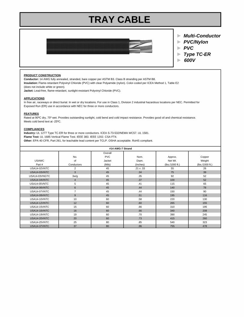
► Multi-Conductor► PVC/Nylon► PVC► Type TC-ER
PRODUCT CONSTRUCTIONConductor: 14 AWG fully annealed, stranded, bare copper per ASTM B3. Class B stranding per ASTM B8.Insulation: Flame-retardant Polyvinyl Chloride (PVC) with clear Polyamide (nylon). Color-coded per ICEA Method 1, Table E2(does not include white or green). Jacket: Lead-free, flame-retardant, sunlight-resistant Polyvinyl Chloride (PVC).
APPLICATIONSIn free air, raceways or direct burial. In wet or dry locations. For use in Class 1, Division 2 industrial hazardous locations per NEC. Permitted for Exposed Run (ER) use in accordance with NEC for three or more conductors.
FEATURESRated at 90ºC dry, 75º wet. Provides outstanding sunlight, cold bend and cold impact resistance. Provides good oil and chemical resistance.Meets cold bend text at -25ºC.
COMPLIANCESIndustry: UL 1277 Type TC-ER for three or more conductors. ICEA S-73-532/NEMA WC57. UL 1581.Flame Test: UL 1685 Vertical Flame Test. IEEE 383. IEEE 1202. CSA FT4.Other: EPA 40 CFR, Part 261, for leachable lead content per TCLP. OSHA acceptable. RoHS compliant.
OverallNo. PVC Nom. Approx. Copper
USAWC of Jacket Diam. Net Wt. WeightPart # Conductors (Mils) (Inches) (lbs./1000 ft.) (lbs./1000 ft.)
USA14-02VNTC 2 45 .21 x .33 55 26USA14-03VNTC 3 45 .34 75 39
USA14-03VNGTC 3w/g 45 .35 92 52USA14-04VNTC 4 45 .37 100 52USA14-05VNTC 5 45 .41 115 65USA14-06VNTC 6 45 .44 140 78USA14-07VNTC 7 45 .44 150 90USA14-09VNTC 9 45 .51 195 116USA14-10VNTC 10 60 .58 220 130USA14-12VNTC 12 60 .60 265 155USA14-15VNTC 15 60 .66 310 195USA14-16VNTC 16 60 .66 340 208USA14-19VNTC 19 60 .70 390 245USA14-20VNTC 20 60 .73 415 260USA14-25VNTC 25 80 .85 540 323USA14-37VNTC 37 80 .96 755 478
► 600V
#14 AWG-7 Strand
TRAY CABLE

► Multi-Conductor► PVC/Nylon► PVC► Type TC-ER► 600V
PRODUCT CONSTRUCTIONConductor: 12 AWG fully annealed, stranded, bare copper per ASTM B3. Class B stranding per ASTM B8.Insulation: Flame-retardant Polyvinyl Chloride (PVC) with clear Polyamide (nylon). Color-coded per ICEA Method 1, Table E2(does not include white or green). Jacket: Lead-free, flame-retardant, sunlight-resistant Polyvinyl Chloride (PVC).
APPLICATIONSIn free air, raceways or direct burial. In wet or dry locations. For use in Class 1, Division 2 industrial hazardous locations per NEC. Permitted for Exposed Run (ER) use in accordance with NEC for three or more conductors.
FEATURESRated at 90ºC dry, 75º wet. Provides outstanding sunlight, cold bend and cold impact resistance. Provides good oil and chemical resistance.Meets cold bend text at -25ºC.
COMPLIANCESIndustry: UL 1277 Type TC-ER for three or more conductors. ICEA S-73-532/NEMA WC57. UL 1581.Flame Test: UL 1685 Vertical Flame Test. IEEE 383. IEEE 1202. CSA FT4.Other: EPA 40 CFR, Part 261, for leachable lead content per TCLP. OSHA acceptable. RoHS compliant.
OverallNo. PVC Nom. Approx. Copper
USAWC of Jacket Diam. Net Wt. WeightPart # Conductors (Mils) (Inches) (lbs./1000 ft.) (lbs./1000 ft.)
USA12-02VNTC 2 45 .23 x .37 75 41USA12-03VNTC 3 45 .36 105 63
USA12-03VNGTC 3w/g 45 .40 130 86USA12-04VNTC 4 45 .40 135 86USA12-05VNTC 5 45 .45 165 108USA12-06VNTC 6 45 .50 195 126USA12-07VNTC 7 45 .50 215 144USA12-09VNTC 9 60 .62 300 185USA12-10VNTC 10 60 .66 325 210USA12-12VNTC 12 60 .68 375 247USA12-15VNTC 15 60 .76 455 315USA12-16VNTC 16 60 .76 485 336USA12-19VNTC 19 60 .79 565 391USA12-20VNTC 20 80 .89 590 420USA12-25VNTC 25 80 .96 770 515USA12-37VNTC 37 80 1.10 1090 762
#12 AWG-7 Strand
TRAY CABLE

► Multi-Conductor► PVC/Nylon► PVC► Type TC-ER► 600V
PRODUCT CONSTRUCTIONConductor: 10 AWG fully annealed, stranded, bare copper per ASTM B3. Class B stranding per ASTM B8.Insulation: Flame-retardant Polyvinyl Chloride (PVC) with clear Polyamide (nylon). Color-coded per ICEA Method 1, Table E2(does not include white or green). Jacket: Lead-free, flame-retardant, sunlight-resistant Polyvinyl Chloride (PVC).
APPLICATIONSIn free air, raceways or direct burial. In wet or dry locations. For use in Class 1, Division 2 industrial hazardous locations per NEC. Permitted for Exposed Run (ER) use in accordance with NEC for three or more conductors.
FEATURESRated at 90ºC dry, 75º wet. Provides outstanding sunlight, cold bend and cold impact resistance. Provides good oil and chemical resistance.Meets cold bend text at -25ºC.
COMPLIANCESIndustry: UL 1277 Type TC-ER for three or more conductors. ICEA S-73-532/NEMA WC57. UL 1581.Flame Test: UL 1685 Vertical Flame Test. IEEE 383. IEEE 1202. CSA FT4.Other: EPA 40 CFR, Part 261, for leachable lead content per TCLP. OSHA acceptable. RoHS compliant.
OverallNo. PVC Nom. Approx. Copper
USAWC of Jacket Diam. Net Wt. WeightPart # Conductors (Mils) (Inches) (lbs./1000 ft.) (lbs./1000 ft.)
USA10-02 VNTC 2 45 .26 x.43 110 65USA10-03 VNTC 3 45 .46 155 98USA10-03VNGTC 3w/g 45 .47 194 131USA10-04VNTC 4 45 .50 200 135USA10-05VNTC 5 60 .58 265 169USA10-06VNTC 6 60 .63 315 192USA10-07VNTC 7 60 .63 345 236USA10-09VNTC 9 60 .73 450 295USA10-10VNTC 10 60 .81 500 320USA10-12VNTC 12 60 .82 580 404USA10-15VNTC 15 80 .95 745 480USA10-16VNTC 16 80 .95 810 512USA10-19VNTC 19 80 1.02 940 608USA10-20VNTC 20 80 1.07 990 640USA10-25VNTC 25 80 1.19 1210 800USA10-37VNTC 37 80 1.36 1710 1184
#10 AWG-7 Strand
TRAY CABLE

► 3C w/Ground► PVC/Nylon► PVC► Type TC-ER► 600V
PRODUCT CONSTRUCTIONConductor: 8 AWG through 1000 kcmil bare, annealed copper per ASTM B3. Class B stranding per ASTM B8.Insulation: Flame-retardant Polyvinyl Chloride (PVC) with clear Polyamide (nylon). Color-coded per ICEA Method 4; individual conductors colored black with conductor number surface printed in contrasting ink.Jacket: Lead-free, flame-retardant, sunlight-resistant Polyvinyl Chloride (PVC).
APPLICATIONSIn free air, raceways or direct burial. In wet or dry locations. For use in Class 1, Division 2 industrial hazardous locations per NEC. Permitted forExposed Run (ER) use in accordance with NEC for three or more conductors.
FEATURESRated at 90ºC dry, 75º wet. Provides outstanding sunlight, cold bend and cold impact resistance. Provides good oil and chemical resistance.Meets cold bend text at -25ºC.
COMPLIANCESIndustry: NEC Type THHN/THWN conductors. UL 1277 Type TC-ER, UL 1581. ICEA S-95-658/NEMA WC70.Flame Test: UL 1685 Vertical Flame Test. IEEE 383. IEEE 1202. CSA FT4.Other: EPA 40 CFR, Part 261, for leachable lead content per TCLP. OSHA acceptable. RoHS compliant.
Size Grounding(AWG No. Overall Nominal Conductor Approx. Copper
USAWC or of PVC Nylon PVC Diameter Size' Net Wt. Weight 90°C 75°CPart # kcmil) Strands Insulation Jacket Jacket (Inches) (AWG) (lbs./1000 ft.) (lbs./1000 ft.) Dry Wet
USA8-03VNGTC 8 7 30 5 60 .62 10 315 189 55 50USA6-03VNGTC 6 7 30 5 60 .70 8 445 300 75 65USA4-03VNGTC 4 7 40 6 80 .88 8 675 446 95 85USA2-03VNGTC 2 7 40 6 80 1.01 6 995 710 130 115USA1-03VNGTC 1 19 50 7 80 1.14 6 1200 855 150 130
USA1/0-03VNGTC 1/0 19 50 7 80 1.23 6 1480 1080 170 150USA2/0-03VNGTC 2/0 19 50 7 80 1.32 6 1770 1340 195 175USA3/0-03VNGTC 3/0 19 50 7 80 1.43 4 2180 1683 225 200USA4/0-03VNGTC 4/0 19 50 7 80 1.56 4 2690 2130 260 230USA250-03VNGTC 250 37 60 8 110 1.76 4 3225 2494 290 255USA350-03VNGTC 350 37 60 8 110 1.98 3 4370 3474 350 310USA500-03VNGTC 500 37 60 8 110 2.26 2 5960 4934 430 380USA750-03VNGTC 750 61 70 9 110 2.71 1 9050 7206 535 475USA1000-03VNGTC 1000 61 70 9 140 3.10 1/0 11720 9584 615 545
Ampacity*Three Conductors With Grounding ConductorThickness in Mils
*AMPACITY in accordance with the NEC for cables in uncovered cable tray without maintained spacing and for cables in raceway or directly buried;90˚C conductor temperature for dry locations, 75˚C conductor temperature for wet locations, 30˚C ambient temperature.
TRAY CABLE

► 4C w/Ground► PVC/Nylon► PVC► Type TC-ER► 600V
PRODUCT CONSTRUCTIONConductor: 8 AWG through 500 kcmil bare, annealed copper per ASTM B3. Class B stranding per ASTM B8.Insulation: Flame-retardant Polyvinyl Chloride (PVC) with clear Polyamide (nylon). Color-coded per ICEA Method 4; individual conductors colored black with conductor number surface printed in contrasting ink.Jacket: Lead-free, flame-retardant, sunlight-resistant Polyvinyl Chloride (PVC).
APPLICATIONSIn free air, raceways or direct burial. In wet or dry locations. For use in Class 1, Division 2 industrial hazardous locations per NEC. Permitted forExposed Run (ER) use in accordance with NEC for three or more conductors.
FEATURESRated at 90ºC dry, 75º wet. Provides outstanding sunlight, cold bend and cold impact resistance. Provides good oil and chemical resistance.Meets cold bend text at -25ºC.
COMPLIANCESIndustry: NEC Type THHN/THWN conductors. UL 1277 Type TC-ER, UL 1581. ICEA S-95-658/NEMA WC70.Flame Test: UL 1685 Vertical Flame Test. IEEE 383. IEEE 1202. CSA FT4.Other: EPA 40 CFR, Part 261, for leachable lead content per TCLP. OSHA acceptable. RoHS compliant.
Size Grounding(AWG No. Overall Nominal Conductor Approx. Copper
USAWC or of PVC Nylon PVC Diameter Size1 Net Wt. Weight 90°C 75°CPart # kcmil) Strands Insulation Jacket Jacket (Inches) (AWG) (lbs./1000 ft.) (lbs./1000 ft.) Dry Wet
USA8-04VNGTC 8 7 30 5 60 .66 10 373 241 55 50USA6-04VNGTC 6 7 30 5 60 .76 8 533 383 75 65USA4-04VNGTC 4 7 40 6 80 .97 8 824 578 95 85USA2-04VNGTC 2 7 40 6 80 1.10 6 1227 919 130 115
USA1/0-04VNGTC 1/0 19 50 7 80 1.36 6 1830 1413 170 150USA2/0-04VNGTC 2/0 19 50 7 80 1.46 6 2252 1760 195 175USA4/0-04VNGTC 4/0 19 50 7 80 1.77 4 3502 2796 260 230USA250-04VNGTC 250 37 60 8 110 1.95 4 4107 3281 290 255USA350-04VNGTC 350 37 60 8 110 2.19 3 5585 4586 350 310USA500-04VNGTC 500 37 60 8 110 2.51 2 7694 6509 430 380
1NOTE: Grounding conductor per UL Standard 1277 for Type TC Tray Cable.
Ampacity*Four Conductors With Grounding ConductorThickness in Mils
*AMPACITY in accordance with the NEC for cables in uncovered cable tray without maintained spacing and for cables in raceway or directly buried;90˚C conductor temperature for dry locations, 75˚C conductor temperature for wet locations, 30˚C ambient temperature.
TRAY CABLE

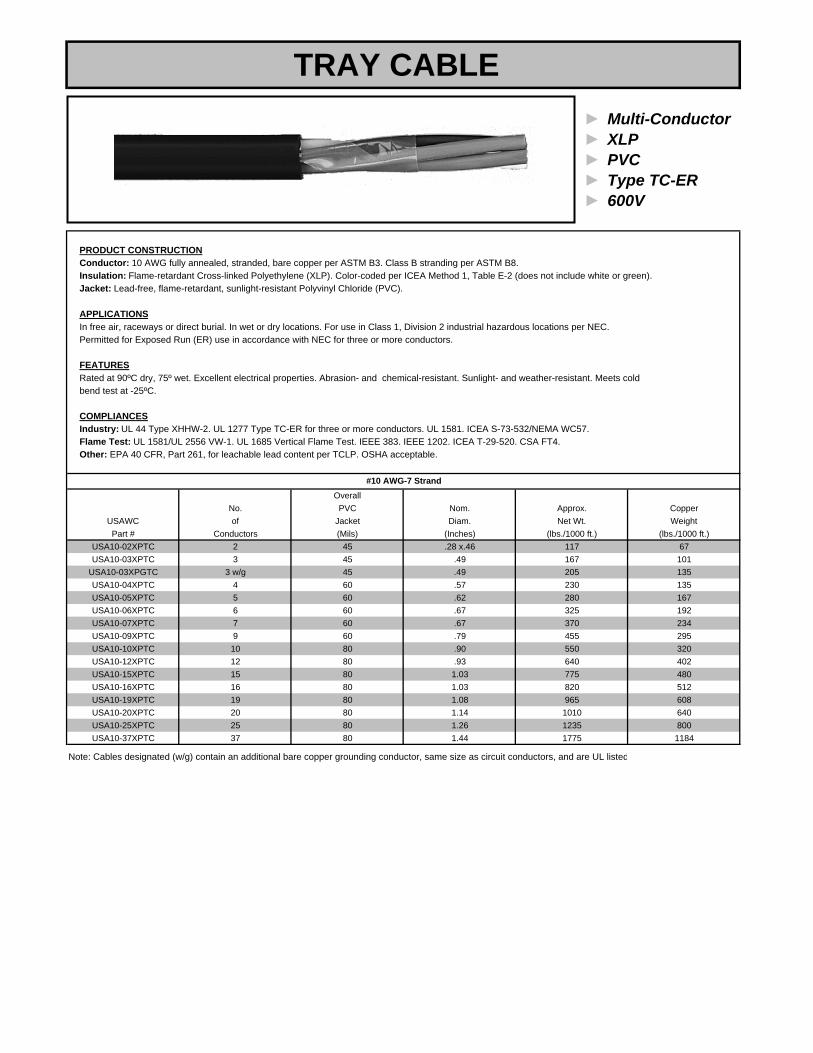
► Multi-Conductor► XLP► PVC► Type TC-ER► 600V
PRODUCT CONSTRUCTIONConductor: 16 AWG fully annealed, stranded, bare copper per ASTM B3. Class B stranding per ASTM B8.Insulation: Flame-retardant Cross-linked Polyethylene (XLP). Color-coded per ICEA Method 1, Table E-2 (does not include white or green).Jacket: Lead-free, flame-retardant, sunlight-resistant Polyvinyl Chloride (PVC).
APPLICATIONSIn free air, raceways or direct burial. In wet or dry locations. For use in Class 1, Division 2 industrial hazardous locations per NEC. Permitted for Exposed Run (ER) use in accordance with NEC for three or more conductors.
FEATURESRated at 90ºC dry, 75º wet. Excellent electrical properties. Abrasion- and chemical-resistant. Sunlight- and weather-resistant. Meets cold bend test at -25ºC.
COMPLIANCESIndustry: UL 44 Type XHHW-2. UL 1277 Type TC-ER for three or more conductors. UL 1581. ICEA S-73-532/NEMA WC57.Flame Test: UL 1581/UL 2556 VW-1. UL 1685 Vertical Flame Test. IEEE 383. IEEE 1202. ICEA T-29-520 (210,000 BTU/hr). CSA FT4. Other: EPA 40 CFR, Part 261, for leachable lead content per TCLP. OSHA acceptable.
OverallNo. PVC Nom. Approx. Copper
#16 AWG-7 Strand
TRAY CABLE
USAWC of Jacket Diam. Net Wt. Weight Part # Conductors (Mils) (Inches) (lbs./1000 ft.) (lbs./1000 ft.)
USA16-02XPTC 2 45 .23 x .35 65 16USA16-03XPTC 3 45 .37 70 22USA16-04XPTC 4 45 .39 87 29USA16-05XPTC 5 45 .44 105 37USA16-06XPTC 6 45 .48 120 44USA16-07XPTC 7 45 .48 140 51USA16-08XPTC 8 45 .51 155 59USA16-09XPTC 9 45 .58 200 66USA16-10XPTC 10 60 .63 230 74USA16-11XPTC 11 60 .63 240 81USA16-12XPTC 12 60 .67 255 88USA16-13XPTC 13 60 .67 270 96USA16-14XPTC 14 60 .68 290 103USA16-15XPTC 15 60 .71 315 110USA16-16XPTC 16 60 .71 325 118USA16-17XPTC 17 60 .75 350 125USA16-18XPTC 18 60 .75 360 132USA16-19XPTC 19 60 .75 370 140USA16-20XPTC 20 60 .79 400 147USA16-23XPTC 23 60 .82 450 169USA16-25XPTC 25 80 .91 530 184USA16-27XPTC 27 80 .93 560 199USA16-29XPTC 29 80 .94 585 213USA16-31XPTC 31 80 .98 625 228USA16-32XPTC 32 80 .99 650 235USA16-37XPTC 37 80 1.03 720 272
Notes: 1. Cables designated (w/g) contain an additional bare copper grounding conductor, same size as circuit conductors, and are UL listed. 2. Standard color coding is Method E-2 of ICEA S-72-532. This color coding method omits white and green from the color sequence. A white or green conductor can be supplied on request, Method E-1.

► Multi-Conductor► XLP► PVC► Type TC-ER► 600V
PRODUCT CONSTRUCTIONConductor: 14 AWG fully annealed, stranded, bare copper per ASTM B3. Class B stranding per ASTM B8.Insulation: Flame-retardant Cross-linked Polyethylene (XLP). Color-coded per ICEA Method 1, Table E-2 (does not include white or green).Jacket: Lead-free, flame-retardant, sunlight-resistant Polyvinyl Chloride (PVC).
APPLICATIONSIn free air, raceways or direct burial. In wet or dry locations. For use in Class 1, Division 2 industrial hazardous locations per NEC. Permitted for Exposed Run (ER) use in accordance with NEC for three or more conductors.
FEATURESRated at 90ºC dry, 75º wet. Excellent electrical properties. Abrasion- and chemical-resistant. Sunlight- and weather-resistant. Meets cold bend test at -25ºC.
COMPLIANCESIndustry: UL 44 Type XHHW-2. UL 1277 Type TC-ER for three or more conductors. UL 1581. ICEA S-73-532/NEMA WC57.Flame Test: UL 1581/UL 2556 VW-1. UL 1685 Vertical Flame Test. IEEE 383. IEEE 1202. ICEA T-29-520 (210,000 BTU/hr). CSA FT4. Other: EPA 40 CFR, Part 261, for leachable lead content per TCLP. OSHA acceptable.
OverallNo. PVC Nom. Approx. Copper
USAWC of Jacket Diam. Net Wt. Weight Part # Conductors (Mils) (Inches) (lbs./1000 ft.) (lbs./1000 ft.)
USA14-02XPTC 2 45 .23 x .37 65 25USA14-03XPTC 3 45 .39 90 40
USA14-03WGXPTC 3+ Grnd 45 .42 110 53USA14-04XPTC 4 45 .43 113 53USA14-05XPTC 5 45 .47 137 66USA14-06XPTC 6 45 .51 160 78USA14-07XPTC 7 45 .51 180 93USA14-09XPTC 9 60 .63 250 119USA14-10XPTC 10 60 .69 270 130USA14-12XPTC 12 60 .70 310 159USA14-15XPTC 15 60 .78 380 195USA14-16XPTC 16 60 .78 400 208USA14-19XPTC 19 60 .82 460 252USA14-20XPTC 20 80 .90 525 260USA14-25XPTC 25 80 1.00 640 323USA14-37XPTC 37 80 1.14 890 490
#14 AWG-7 Strand
TRAY CABLE

► Multi-Conductor► XLP► PVC► Type TC-ER
PRODUCT CONSTRUCTIONConductor: 12 AWG fully annealed, stranded, bare copper per ASTM B3. Class B stranding per ASTM B8.Insulation: Flame-retardant Cross-linked Polyethylene (XLP). Color-coded per ICEA Method 1, Table E-2.Jacket: Lead-free, flame-retardant, sunlight-resistant Polyvinyl Chloride (PVC).
APPLICATIONSIn free air, raceways or direct burial. In wet or dry locations. For use in Class 1, Division 2 industrial hazardous locations per NEC. Permitted for Exposed Run (ER) use in accordance with NEC for three or more conductors.
FEATURESRated at 90ºC dry, 75º wet. Excellent electrical properties. Abrasion- and chemical-resistant. Sunlight- and weather-resistant. Meets cold bend test at -25ºC.
COMPLIANCESIndustry: UL 44 Type XHHW-2. UL 1277 Type TC-ER for three or more conductors. UL 1581. ICEA S-73-532/NEMA WC57.Flame Test: UL 1581/UL 2556 VW-1. UL 1685 Vertical Flame Test. IEEE 383. IEEE 1202. ICEA T-29-520 (210,000 BTU/hr). CSA FT4. Other: EPA 40 CFR, Part 261, for leachable lead content per TCLP. OSHA acceptable.
OverallNo. PVC Nom. Approx. Copper
USAWC of Jacket Diam. Net Wt. Weight Part # Conductors (Mils) (Inches) (lbs./1000 ft.) (lbs./1000 ft.)
USA12-02XPTC 2 45 .25 x.41 85 41USA12-03XPTC 3 45 .44 120 65
USA12-03XPGTC 3 w/g 45 .44 143 86USA12-04XPTC 4 45 .48 154 86USA12-05XPTC 5 45 .53 190 108USA12-06XPTC 6 60 .60 235 126USA12-07XPTC 7 60 .60 265 150USA12-09XPTC 9 60 .70 340 193USA12-10XPTC 10 60 .77 370 210USA12-12XPTC 12 60 .79 430 258USA12-15XPTC 15 80 .92 535 315USA12-16XPTC 16 80 .92 570 336USA12-19XPTC 19 80 .96 675 403USA12-20XPTC 20 80 1.01 710 420USA12-25XPTC 25 80 1.12 890 515USA12-37XPTC 37 80 1.28 1310 741
Note: Cables designated (w/g) contain an additional bare copper grounding conductor, same size as circuit conductors, and are UL listed
#12 AWG-7 Strand
► 600V
TRAY CABLE
► Multi-Conductor► XLP► PVC► Type TC-ER► 600V
PRODUCT CONSTRUCTIONConductor: 10 AWG fully annealed, stranded, bare copper per ASTM B3. Class B stranding per ASTM B8.Insulation: Flame-retardant Cross-linked Polyethylene (XLP). Color-coded per ICEA Method 1, Table E-2 (does not include white or green).Jacket: Lead-free, flame-retardant, sunlight-resistant Polyvinyl Chloride (PVC).
APPLICATIONSIn free air, raceways or direct burial. In wet or dry locations. For use in Class 1, Division 2 industrial hazardous locations per NEC. Permitted for Exposed Run (ER) use in accordance with NEC for three or more conductors.
FEATURESRated at 90ºC dry, 75º wet. Excellent electrical properties. Abrasion- and chemical-resistant. Sunlight- and weather-resistant. Meets cold bend test at -25ºC.
COMPLIANCESIndustry: UL 44 Type XHHW-2. UL 1277 Type TC-ER for three or more conductors. UL 1581. ICEA S-73-532/NEMA WC57.Flame Test: UL 1581/UL 2556 VW-1. UL 1685 Vertical Flame Test. IEEE 383. IEEE 1202. ICEA T-29-520. CSA FT4. Other: EPA 40 CFR, Part 261, for leachable lead content per TCLP. OSHA acceptable.
OverallNo. PVC Nom. Approx. Copper
USAWC of Jacket Diam. Net Wt. Weight Part # Conductors (Mils) (Inches) (lbs./1000 ft.) (lbs./1000 ft.)
USA10-02XPTC 2 45 .28 x.46 117 67USA10-03XPTC 3 45 .49 167 101
USA10-03XPGTC 3 w/g 45 .49 205 135USA10-04XPTC 4 60 .57 230 135USA10-05XPTC 5 60 .62 280 167USA10-06XPTC 6 60 .67 325 192USA10-07XPTC 7 60 .67 370 234USA10-09XPTC 9 60 .79 455 295USA10-10XPTC 10 80 .90 550 320USA10-12XPTC 12 80 .93 640 402USA10-15XPTC 15 80 1.03 775 480USA10-16XPTC 16 80 1.03 820 512USA10-19XPTC 19 80 1.08 965 608USA10-20XPTC 20 80 1.14 1010 640USA10-25XPTC 25 80 1.26 1235 800USA10-37XPTC 37 80 1.44 1775 1184
Note: Cables designated (w/g) contain an additional bare copper grounding conductor, same size as circuit conductors, and are UL listed
#10 AWG-7 Strand
TRAY CABLE

► 3C w/Ground► XLP► PVC► Type TC-ER► 600V
PRODUCT CONSTRUCTIONConductor: 8 AWG through 1000 kcmil bare, annealed copper per ASTM B3. Class B stranding per ASTM B8.Insulation: Flame-retardant Cross-linked Polyethylene (XLP). Color-coded per ICEA Method 4; individual conductors colored black with conductornumber surface printed in contrasting ink.Jacket: Lead-free, flame-retardant, sunlight-resistant Polyvinyl Chloride (PVC).
APPLICATIONSIn free air, raceways or direct burial. In wet or dry locations. For use in Class 1, Division 2 industrial hazardous locations per NEC. Permitted for Exposed Run (ER) use in accordance with NEC.
FEATURESRated at 90ºC wet or dry. Excellent electrical properties. Abrasion- and chemical-resistant. Sunlight- and weather-resistant. Meets cold bend test at -25ºC.
COMPLIANCESIndustry: UL 44 Type XHHW-2. UL 1277 Type TC-ER. UL 1581. ICEA S-95-658/NEMA WC70.Flame Test: UL 1581/UL 2556 VW-1. UL 1685 Vertical Flame Test. IEEE 383. IEEE 1202. ICEA T-29-520. CSA FT4.Other: EPA 40 CFR, Part 261, for leachable lead content per TCLP. OSHA acceptable.
Size GroundingCopper
USAWC WeightPart # kcmil Strands Insulation Jacket (Inches) (AWG) (lbs./1000 ft.) (lbs./1000 ft.) 90°C 75°C
USA8-03XPGTC 8 7 45 60 .66 10 325 190 55 50USA6-03XPGTC 6 7 45 60 .74 8 450 301 75 65USA4-03XPGTC 4 7 45 80 .88 8 655 448 95 85USA2-03XPGTC 2 7 45 80 1.00 6 960 716 130 115USA1-03XPGTC 1 19 55 80 1.13 6 1170 872 150 130
USA1/0-03XPGTC 1/0 19 55 80 1.22 6 1435 1081 170 150USA2/0-03XPGTC 2/0 19 55 80 1.31 6 1730 1341 195 175USA3/0-03XPGTC 3/0 19 55 80 1.42 4 2150 1717 225 200USA4/0-03XPGTC 4/0 19 55 80 1.55 4 2620 2132 260 230USA250-03XPGTC 250 37 65 110 1.76 4 3180 2494 290 255USA350-03XPGTC 350 37 65 110 1.98 3 4290 3474 350 310USA500-03XPGTC 500 37 65 110 2.26 2 5940 4938 430 380USA750-03XPGTC 750 61 80 110 2.71 1 8660 7278 535 475
USA1000-03XPGTC 1000 61 80 140 3.10 1/0 11700 9590 615 545
AWGor
No.of
NominalDiameter
Ampacity*Conductor
Size
*AMPACITY in accordance with the NEC for cables in uncovered cable tray without maintained spacing and for cables in raceway or directly buried;at the conductor temperature indicated, in wet or dry locations, 30̊C ambient temperature.
Approx.Net Wt.
Thickness in Mils
Three Conductors With Grounding Conductor
TRAY CABLE

► 4C w/Ground► XLP► PVC► Type TC-ER► 600V
PRODUCT CONSTRUCTIONConductor: 8 AWG through 750 kcmil bare, annealed copper per ASTM B3. Class B stranding per ASTM B8.Insulation: Flame-retardant Cross-linked Polyethylene (XLP). Color-coded per ICEA Method 4; individual conductors colored black with conductornumber surface printed in contrasting ink.Jacket: Lead-free, flame-retardant, sunlight-resistant Polyvinyl Chloride (PVC).
APPLICATIONSIn free air, raceways or direct burial. In wet or dry locations. For use in Class 1, Division 2 industrial hazardous locations per NEC. Permitted for Exposed Run (ER) use in accordance with NEC.
FEATURESRated at 90ºC wet or dry. Excellent electrical properties. Abrasion- and chemical-resistant. Sunlight- and weather-resistant. Meets cold bend test at -25ºC.
COMPLIANCESIndustry: UL 44 Type XHHW-2. UL 1277 Type TC-ER. UL 1581. ICEA S-95-658/NEMA WC70.Flame Test: UL 1581/UL 2556 VW-1. UL 1685 Vertical Flame Test. IEEE 383. IEEE 1202. ICEA T-29-520. CSA FT4.Other: EPA 40 CFR, Part 261, for leachable lead content per TCLP. OSHA acceptable.
Size GroundingCopper
USAWC WeightPart # kcmil Strands Insulation Jacket (Inches) (AWG) (lbs./1000 ft.) (lbs./1000 ft.) 90°C 75°C
USA8-04XPGTC 8 7 45 60 .72 12 415 242 44 40USA6-04XPGTC 6 7 45 60 .81 10 575 384 60 52USA4-04XPGTC 4 7 45 80 .96 10 840 578 76 68USA2-04XPGTC 2 7 45 80 1.10 9 1200 919 104 92USA1-04XPGTC 1 19 55 80 1.25 9 1545 1136 120 104
USA1/0-04XPGTC 1/0 19 55 80 1.35 9 1835 1413 136 120USA2/0-04XPGTC 2/0 19 55 80 1.45 9 2195 1760 156 140USA3/0-04XPGTC 3/0 19 55 80 1.58 7 2800 2245 180 160USA4/0-04XPGTC 4/0 19 55 80 1.77 7 3460 2796 208 184USA250-04XPGTC 250 37 65 110 1.93 7 4040 3282 232 204USA350-04XPGTC 350 37 65 110 2.18 6 5475 4577 280 248USA500-04XPGTC 500 37 65 110 2.50 5 7635 6509 344 304USA750-04XPGTC 750 61 80 140 3.12 4 11400 9712 428 380
NOTES: (1) Grounding conductor per UL Standard 1277 for Type TC Tray Cable. (2) Cables with Open Wiring listing available upon request.at the conductor temperature indicated, in wet or dry locations, 30˚C ambient temperature.
Approx.Net Wt.
Thickness in Mils
Four Conductors With Grounding Conductor
AWGor
No.of
NominalDiameter
Ampacity*Conductor
Size
*AMPACITY in accordance with the NEC for cables in uncovered cable tray without maintained spacing and for cables in raceway or directly buried;
TRAY CABLE

► Multi-Conductor► FR-XLP► CPE► Type TC-ER► 600V
PRODUCT CONSTRUCTIONConductor: 14 AWG fully annealed, stranded, tinned copper per ASTM B33. Class B stranding per ASTM B8.Insulation: Flame-retardant Cross-linked Polyethylene (XLP). Color-coded per ICEA Method 1, Table E2(does not include white or green). Jacket: Lead-free Chlorinated Polyethylene (CPE).
APPLICATIONSIn free air, raceways or direct burial. In wet or dry locations. For use in Class 1, Division 2 industrial hazardous locations For use in Class 1, Division 2 industrial hazardous locations per NEC Article 501 and Class 1 circuits per NEC.
FEATURESRated at 90ºC wet or dry. Excellent physical, thermal and electrical properties. Excellent resistance to moisture and flame. Sunlight- and weather-resistant. Meets cold bend test at -35ºC.
COMPLIANCESIndustry: UL 44 Type XHHW-2. UL 1277 Type TC. UL 1581. ICEA S-73-532/NEMA WC57.Flame Test: UL 1581/UL 2556 VW-1. UL 1685 Vertical Flame Test. IEEE 383. IEEE 1202. CSA FT4. ICEA T-29-520.Other: EPA 40 CFR, Part 261, for leachable lead content per TCLP. OSHA acceptable.
No. Overall Nom. Approx. CopperUSAWC of Jacket Diam. Net Wt. Weight
Part # Conductors (Mils) (Inches) (lbs./1000 ft.) (lbs./1000 ft.)USA14-02XLPCPETC 2 45 .23 x.37 65 25USA14-03XLPCPETC 3 45 .39 90 40
USA14-03WGXLPCPETC 3+ Grnd 45 .39 109 53USA14-04XLPCPETC 4 45 .43 113 53USA14-05XLPCPETC 5 45 .47 137 66USA14-07XLPCPETC 7 45 .51 180 93USA14-09XLPCPETC 9 60 .63 250 119USA14-10XLPCPETC 10 60 .69 270 130USA14-12XLPCPETC 12 60 .70 310 159USA14-16XLPCPETC 16 60 .78 400 208USA14-19XLPCPETC 19 60 .82 460 252USA14-20XLPCPETC 20 80 .90 525 260USA14-25XLPCPETC 25 80 1.00 640 323USA14-37XLPCPETC 37 80 1.14 890 490
#14 AWG-7 Strand
TRAY CABLE

► Multi-Conductor► FR-XLP► CPE► Type TC-ER
PRODUCT CONSTRUCTIONConductor: 12 AWG fully annealed, stranded, tinned copper per ASTM B33. Class B stranding per ASTM B8.Insulation: Flame-retardant Cross-linked Polyethylene (XLP). Color-coded per ICEA Method 1, Table E2(does not include white or green). Jacket: Lead-free Chlorinated Polyethylene (CPE).
APPLICATIONSIn free air, raceways or direct burial. In wet or dry locations. For use in Class 1, Division 2 industrial hazardous locations For use in Class 1, Division 2 industrial hazardous locations per NEC Article 501 and Class 1 circuits per NEC.
FEATURESRated at 90ºC wet or dry. Excellent physical, thermal and electrical properties. Excellent resistance to moisture and flame. Sunlight- and weather-resistant. Meets cold bend test at -35ºC.
COMPLIANCESIndustry: UL 44 Type XHHW-2. UL 1277 Type TC. UL 1581. ICEA S-73-532/NEMA WC57.Flame Test: UL 1581/UL 2556 VW-1. UL 1685 Vertical Flame Test. IEEE 383. IEEE 1202. CSA FT4. ICEA T-29-520.Other: EPA 40 CFR, Part 261, for leachable lead content per TCLP. OSHA acceptable.
No. Overall Nom. Approx. CopperUSAWC of Jacket Diam. Net Wt. Weight
Part # Conductors (Mils) (Inches) (lbs./1000 ft.) (lbs./1000 ft.)USA12-02XLPCPETC 2 45 .25x.41 85 41USA12-03XLPCPETC 3 45 .44 120 65USA12-04XLPCPETC 4 45 .48 154 86USA12-05XLPCPETC 5 45 .53 190 108USA12-07XLPCPETC 7 60 .60 265 150USA12-09XLPCPETC 9 60 .70 340 193USA12-10XLPCPETC 10 60 .77 370 210USA12-12XLPCPETC 12 60 .79 430 258USA12-16XLPCPETC 16 80 .92 570 336USA12-19XLPCPETC 19 80 .96 675 403USA12-20XLPCPETC 20 80 1.01 710 420USA12-25XLPCPETC 25 80 1.12 890 515USA12-37XLPCPETC 37 80 1.28 1310 741
.2. Standard color coding is ICEA Method E-2 for NEC applications per ICEA S-73-532. This color coding method omits white and green
► 600V
#12 AWG-7 Strand
Notes: 1. All cables available with bare or covered grounding indicator.
from the color sequence. A white or green conductor can be supplied on request, Method E-1.
TRAY CABLE

► Multi-Conductor► FR-XLP► CPE► Type TC-ER
PRODUCT CONSTRUCTIONConductor: 10 AWG fully annealed, stranded, tinned copper per ASTM B33. Class B stranding per ASTM B8.Insulation: Flame-retardant Cross-linked Polyethylene (XLP). Color-coded per ICEA Method 1, Table E2(does not include white or green). Jacket: Lead-free Chlorinated Polyethylene (CPE).
APPLICATIONSIn free air, raceways or direct burial. In wet or dry locations. For use in Class 1, Division 2 industrial hazardous locations For use in Class 1, Division 2 industrial hazardous locations in accordance with the NEC for three or more conductors.
FEATURESRated at 90ºC wet or dry. Excellent physical, thermal and electrical properties. Excellent resistance to moisture and flame. Sunlight- and weather-resistant. Meets cold bend test at -35ºC.
COMPLIANCESIndustry: UL 44 Type XHHW-2. UL 1277 Type TC. UL 1581. ICEA S-73-532/NEMA WC57.Flame Test: UL 1581/UL 2556 VW-1. UL 1685 Vertical Flame Test. IEEE 383. IEEE 1202. CSA FT4. ICEA T-29-520.Other: EPA 40 CFR, Part 261, for leachable lead content per TCLP. OSHA acceptable.
No. Overall Nom. Approx. CopperUSAWC of Jacket Diam. Net Wt. Weight
Part # Conductors (Mils) (Inches) (lbs./1000 ft.) (lbs./1000 ft.)USA10-02XLPCPETC 2 45 .28 x.46 117 67USA10-03XLPCPETC 3 45 .49 167 101USA10-04XLPCPETC 4 60 .57 230 135USA10-05XLPCPETC 5 60 .62 280 167USA10-07XLPCPETC 7 60 .67 370 234USA10-09XLPCPETC 9 60 .79 455 295USA10-10XLPCPETC 10 80 .90 550 320USA10-12XLPCPETC 12 80 .93 640 402USA10-16XLPCPETC 16 80 1.03 820 512USA10-19XLPCPETC 19 80 1.08 965 608USA10-20XLPCPETC 20 80 1.14 1010 640USA10-25XLPCPETC 25 80 1.26 1235 800USA10-37XLPCPETC 37 80 1.44 1775 1184
.2. Standard color coding is ICEA Method E-2 for NEC applications per ICEA S-73-532. This color coding method omits white and green
► 600V
#10 AWG-7 Strand
Notes: 1. All cables available with bare or covered grounding indicator.
from the color sequence. A white or green conductor can be supplied on request, Method E-1.
TRAY CABLE

► 3C w/Ground► FR-XLP► CPE► Type TC-ER► 600V
PRODUCT CONSTRUCTIONConductor: 8 AWG through 1000 kcmil tinned, annealed copper per ASTM B33. Class B stranding per ASTM B8.Insulation: Flame-retardant Cross-linked Polyethylene (XLPE). Color-coded per ICEA Method 4; individual conductors colored black with conductornumber surface printed in contrasting ink.Jacket: Lead-free Chlorinated Polyethylene (CPE).
APPLICATIONSIn free air, raceways or direct burial. In wet or dry locations. For use in Class 1, Division 2 industrial hazardous locations per NEC Article 501 and Class 1circuits per NEC. Permitted for Exposed Run (ER) use in accordance with NEC for 2 AWG and larger.
FEATURESRated at 90ºC wet or dry. Excellent physical, thermal and electrical properties. Excellent resistance to moisture and flame. Sunlight- andweather-resistant. Meets cold bend test at -35ºC. Meets crush and impact requirements of Type MC Cable for 2AWG and larger.
COMPLIANCESIndustry: UL 44 Type XHHW-2. UL 1277 Type TC-ER for 2 AWG and larger. UL 1581. ICEA S-95-658/NEMA WC70.Flame Test: UL 1581/UL 2556 VW-1. UL 1685 Vertical Flame Test. IEEE 383. IEEE 1202. CSA FT4. ICEA T-29-520.Other: EPA 40 CFR, Part 261, for leachable lead content per TCLP. OSHA acceptable.
Size GroundingAWG No. Nominal Conductor Approx. Copper
USAWC or of Diameter Size Net Wt. WeightPart # kcmil Strands Insulation Jacket (Inches) (AWG) (lbs./1000 ft.) (lbs./1000 ft.)
USA8-03XLPGCPETC 8 7 45 60 .66 10 335 190 55 50USA6-03XLPGCPETC 6 7 45 60 .74 8 475 301 75 65USA4-03XLPGCPETC 4 7 45 80 .88 8 700 448 95 85USA2-03XLPGCPETC 2 7 45 80 1.00 6 1020 716 130 115USA1-03XLPGCPETC 1 19 55 80 1.13 6 1260 872 150 130
USA1/0-03XLPGCPETC 1/0 19 55 80 1.22 6 1520 1081 170 150USA2/0-03XLPGCPETC 2/0 19 55 80 1.31 6 1825 1341 195 175USA3/0-03XLPGCPETC 3/0 19 55 80 1.42 4 2210 1717 225 200USA4/0-03XLPGCPETC 4/0 19 55 80 1.55 4 2690 2132 260 230USA250-03XLPGCPETC 250 37 65 110 1.76 4 3265 2494 290 255USA350-03XLPGCPETC 350 37 65 110 1.98 3 4465 3474 350 310USA500-03XLPGCPETC 500 37 65 110 2.26 2 6100 4938 430 380USA750-03XLPGCPETC 750 61 80 110 2.71 1 9060 7206 535 475USA1000-03XPGCPETC 1000 61 80 140 3.10 1/0 11770 9590 615 545
Three Conductors With Grounding Conductor
temperature for dry locations, 75̊ C conductor temperature for wet locations, 30˚C ambient temperature.NOTE: Grounding conductor per UL Standard 1277 for Type TC Tray Cable.
Thickness in Mils
90°C 75°C
Ampacity*
*AMPACITY in accordance with the NEC for cables in uncovered cable tray without maintained spacing and for cables in raceway or directly buried; 90̊C conductor
TRAY CABLE

► 4C w/Ground► FR-XLP► CPE► Type TC-ER► 600V
PRODUCT CONSTRUCTIONConductor: 8 AWG through 750 kcmil tinned, annealed copper per ASTM B33. Class B stranding per ASTM B8.Insulation: Flame-retardant Cross-linked Polyethylene (XLPE). Color-coded per ICEA Method 4; individual conductors colored black with conductornumber surface printed in contrasting ink.Jacket: Lead-free Chlorinated Polyethylene (CPE).
APPLICATIONSIn free air, raceways or direct burial. In wet or dry locations. For use in Class 1, Division 2 industrial hazardous locations per NEC Article 501 and Class 1circuits per NEC. Permitted for Exposed Run (ER).
FEATURESRated at 90ºC wet or dry. Excellent physical, thermal and electrical properties. Excellent resistance to moisture and flame. Sunlight- andweather-resistant. Meets cold bend test at -35ºC. Meets crush and impact requirements of Type MC Cable for 2AWG and larger.
COMPLIANCESIndustry: UL 44 Type XHHW-2. UL 1277 Type TC-ER for 2 AWG and larger. UL 1581. ICEA S-95-658/NEMA WC70.Flame Test: UL 1581/UL 2556 VW-1. UL 1685 Vertical Flame Test. IEEE 383. IEEE 1202. CSA FT4. ICEA T-29-520.Other: EPA 40 CFR, Part 261, for leachable lead content per TCLP. OSHA acceptable.
Size GroundingAWG No. Nominal Conductor Approx. Copper
USAWC or of Diameter Size Net Wt. WeightPart # kcmil Strands Insulation Jacket (Inches) (AWG) (lbs./1000 ft.) (lbs./1000 ft.)
USA8-04XLPGCPETC 8 7 45 60 .71 10 385 242 55 50USA6-04XLPGCPETC 6 7 45 60 .79 8 558 384 75 65USA4-04XLPGCPETC 4 7 45 80 .95 8 820 578 95 85USA2-04XLPGCPETC 2 7 45 80 1.10 6 1214 919 130 115USA1-04XLPGCPETC 1 19 55 80 1.24 6 1704 1136 150 130
USA1/0-04XLPGCPETC 1/0 19 55 80 1.34 6 1825 1413 170 150USA2/0-04XLPGCPETC 2/0 19 55 80 1.45 6 2223 1760 195 175USA3/0-04XLPGCPETC 3/0 19 55 80 1.57 4 3123 2245 225 200USA4/0-04XLPGCPETC 4/0 19 55 80 1.77 4 3444 2796 260 230USA250-04XLPGCPETC 250 37 65 110 1.93 4 4048 3282 290 255USA350-04XLPGCPETC 350 37 65 110 2.18 3 5470 4577 350 310USA500-04XLPGCPETC 500 37 65 110 2.48 2 7579 6509 430 380USA750-04XLPGCPETC 750 61 80 110 3.12 1 11746 9522 535 475
Four Conductors With Grounding Conductor
temperature for dry locations, 75˚C conductor temperature for wet locations, 30˚C ambient temperature.NOTE: Grounding conductor per UL Standard 1277 for Type TC Tray Cable.
Thickness in Mils
90°C 75°C
Ampacity*
*AMPACITY in accordance with the NEC for cables in uncovered cable tray without maintained spacing and for cables in raceway or directly buried; 90˚C conductor
TRAY CABLE

► Multi-Conductor► FR-EPR► CPE► Type TC-ER► 600V
PRODUCT CONSTRUCTIONConductor: 14 AWG fully annealed, stranded, tinned copper per ASTM B33. Class B stranding per ASTM B8.Insulation: Flame-retardant Ethylene Propylene Rubber (FR-EPR) Type II. Color-coded per ICEA Method 1, Table E2 (does not include white or green). Jacket: Lead-free, flame-retardant thermoplastic Chlorinated Polyethylene (CPE).
APPLICATIONSIn free air, raceways or direct burial. In wet or dry locations. For use in Class 1, Division 2 industrial hazardous locations per NEC. Permitted forExposed Run (ER) use in accordance with NEC for three or more conductors.
FEATURESRated at 90ºC wet or dry. Excellent physical, thermal and electrical properties. Excellent resistance to moisture and flame. Sunlight- and weather-resistant. Meets cold bend test at -40ºC.
COMPLIANCESIndustry: UL 44 Type XHHW-2. UL 1277 Type TC-ER for three or more conductors. UL 1581. ICEA S-73-532/NEMA WC57.Flame Test: UL 1581/UL 2556 VW-1. UL 1685 Vertical Flame Test. IEEE 383. IEEE 1202. CSA FT4. ICEA T-29-520.Other: EPA 40 CFR, Part 261, for leachable lead content per TCLP. OSHA acceptable.
OverallNo. CPE Nom. Approx. Copper
USAWC of Jacket Diam. Net Wt. WeightPart # Conductors (Mils) (Inches) (lbs./1000 ft.) (lbs./1000 ft.)
USA14-02FREPCPETC 2 45 .25 x.37 65 26USA14-03FREPCPETC 3 45 .39 90 39USA14-04FREPCPETC 4 45 .43 113 53USA14-05FREPCPETC 5 45 .47 137 66USA14-07FREPCPETC 7 45 .51 180 92USA14-09FREPCPETC 9 60 .63 250 118USA14-10FREPCPETC 10 60 .69 270 130USA14-12FREPCPETC 12 60 .70 310 158USA14-16FREPCPETC 16 60 .78 400 208USA14-19FREPCPETC 19 60 .82 460 250USA14-20FREPCPETC 20 80 .90 525 260USA14-25FREPCPETC 25 80 1.00 640 323USA14-37FREPCPETC 37 80 1.14 890 466
2. Standard color coding is ICEA Method E-2 for NEC applications per ICEA S-73-532. This color coding method omits white and green
#14 AWG – 7 Strand
Notes: 1. All cables available with bare or covered grounding indicator.
from the color sequence. A white or green conductor can be supplied on request, Method E-1.
TRAY CABLE

► Multi-Conductor► FR-EPR► CPE► Type TC-ER► 600V
PRODUCT CONSTRUCTIONConductor: 12 AWG fully annealed, stranded, tinned copper per ASTM B33. Class B stranding per ASTM B8.Insulation: Flame-retardant Ethylene Propylene Rubber (FR-EPR) Type II. Color-coded per ICEA Method 1, Table E2 (does not include white or green). Jacket: Lead-free, flame-retardant thermoplastic Chlorinated Polyethylene (CPE).
APPLICATIONSIn free air, raceways or direct burial. In wet or dry locations. For use in Class 1, Division 2 industrial hazardous locations per NEC. Permitted forExposed Run (ER) use in accordance with NEC for three or more conductors.
FEATURESRated at 90ºC wet or dry. Excellent physical, thermal and electrical properties. Excellent resistance to moisture and flame. Sunlight- and weather-resistant. Meets cold bend test at -40ºC.
COMPLIANCESIndustry: UL 44 Type XHHW-2. UL 1277 Type TC-ER for three or more conductors. UL 1581. ICEA S-73-532/NEMA WC57.Flame Test: UL 1581/UL 2556 VW-1. UL 1685 Vertical Flame Test. IEEE 383. IEEE 1202. CSA FT4. ICEA T-29-520.Other: EPA 40 CFR, Part 261, for leachable lead content per TCLP. OSHA acceptable.
OverallNo. CPE Nom. Approx. Copper
USAWC of Jacket Diam. Net Wt. WeightPart # Conductors (Mils) (Inches) (lbs./1000 ft.) (lbs./1000 ft.)
USA12-02FREPCPETC 2 45 .25 x.41 85 41USA12-03FREPCPETC 3 45 .44 120 64
USA12-03WGFREPCPETC 3+ Grnd 45 .44 148 85USA12-04FREPCPETC 4 45 .48 154 85USA12-05FREPCPETC 5 45 .53 190 106USA12-07FREPCPETC 7 60 .60 265 149USA12-09FREPCPETC 9 60 .70 340 191USA12-10FREPCPETC 10 60 .77 370 210USA12-12FREPCPETC 12 60 .79 430 247USA12-16FREPCPETC 16 80 .92 570 336USA12-19FREPCPETC 19 80 .96 675 391USA12-20FREPCPETC 20 80 1.01 710 420USA12-25FREPCPETC 25 80 1.12 890 515USA12-37FREPCPETC 37 80 1.28 1310 762
2. Standard color coding is ICEA Method E-2 for NEC applications per ICEA S-73-532. This color coding method omits white and green
#12 AWG – 7 Strand
Notes: 1. All cables available with bare or covered grounding indicator.
from the color sequence. A white or green conductor can be supplied on request, Method E-1.
TRAY CABLE

► Multi-Conductor► FR-EPR► CPE► Type TC-ER
PRODUCT CONSTRUCTIONConductor: 10 AWG fully annealed, stranded, tinned copper per ASTM B33. Class B stranding per ASTM B8.Insulation: Flame-retardant Ethylene Propylene Rubber (FR-EPR) Type II. Color-coded per ICEA Method 1, Table E2 (does not include white or green). Jacket: Lead-free, flame-retardant thermoplastic Chlorinated Polyethylene (CPE).
APPLICATIONSIn free air, raceways or direct burial. In wet or dry locations. For use in Class 1, Division 2 industrial hazardous locations per NEC. Permitted forExposed Run (ER) use in accordance with NEC for three or more conductors.
FEATURESRated at 90ºC wet or dry. Excellent physical, thermal and electrical properties. Excellent resistance to moisture and flame. Sunlight- and weather-resistant. Meets cold bend test at -40ºC.
COMPLIANCESIndustry: UL 44 Type XHHW-2. UL 1277 Type TC-ER for three or more conductors. UL 1581. ICEA S-73-532/NEMA WC57.Flame Test: UL 1581/UL 2556 VW-1. UL 1685 Vertical Flame Test. IEEE 383. IEEE 1202. CSA FT4. ICEA T-29-520.Other: EPA 40 CFR, Part 261, for leachable lead content per TCLP. OSHA acceptable.
OverallNo. CPE Nom. Approx. Copper
USAWC of Jacket Diam. Net Wt. WeightPart # Conductors (Mils) (Inches) (lbs./1000 ft.) (lbs./1000 ft.)
USA10-02FREPCPETC 2 45 .28 x.46 117 65USA10-03FREPCPETC 3 45 .49 167 100USA10-04FREPCPETC 4 60 .57 230 134USA10-05FREPCPETC 5 60 .62 280 167USA10-07FREPCPETC 7 60 .67 370 234USA10-09FREPCPETC 9 60 .79 455 295USA10-10FREPCPETC 10 80 .90 550 320USA10-12FREPCPETC 12 80 .93 640 402USA10-16FREPCPETC 16 80 1.03 820 512USA10-19FREPCPETC 19 80 1.08 965 608USA10-20FREPCPETC 20 80 1.14 1010 640USA10-25FREPCPETC 25 80 1.26 1235 800USA10-37FREPCPETC 37 80 1.44 1775 1184
2. Standard color coding is ICEA Method E-2 for NEC applications per ICEA S-73-532. This color coding method omits white and green Notes: 1. All cables available with bare or covered grounding indicator.
from the color sequence. A white or green conductor can be supplied on request, Method E-1.
#10 AWG – 7 Strand
► 600V
TRAY CABLE

► 3C w/Ground► FR-EPR► CPE► Type TC-ER► 600V
PRODUCT CONSTRUCTIONConductor: 8 AWG through 1000 kcmil tinned, annealed copper per ASTM B33. Class B stranding per ASTM B8.Insulation: Flame-retardant Ethylene Propylene Rubber (FR-EPR) Type II. Color-coded per ICEA Method 4; individual conductors colored blackwith conductor number surface printed in contrasting ink.Jacket: Lead-free, flame-retardant thermoplastic Chlorinated Polyethylene (CPE).
APPLICATIONSIn free air, raceways or direct burial. In wet or dry locations. For use in Class 1, Division 2 industrial hazardous locations per NEC. Permitted for Division 2 industrial hazardous locations per NEC. Permitted for Exposed Run (ER)
FEATURESRated at 90ºC wet or dry. Excellent physical, thermal and electrical properties. Excellent resistance to moisture and flame. Sunlight- and weather-resistant. Meets cold bend test at -40ºC.
COMPLIANCESIndustry: UL 44 Type XHHW-2. UL 1277 Type TC-ER. UL 1581. ICEA S-73-532/NEMA WC57.Flame Test: UL 1581/UL 2556 VW-1. UL 1685 Vertical Flame Test. IEEE 383. IEEE 1202. CSA FT4. ICEA T-29-520.Other: EPA 40 CFR, Part 261, for leachable lead content per TCLP. OSHA acceptable.
Size GroundingAWG No. Nominal Conductor Approx. Copper
USAWC or of Diameter Size Net Wt. WeightPart # kcmil Strands Insulation Jacket (Inches) (AWG) (lbs./1000 ft.) (lbs./1000 ft.)
USA14-03EPGCPETC 14 7 30 45 .39 14 118 55USA12-03EPGCPETC 12 7 30 45 .44 12 160 87USA10-03EPGCPETC 10 7 30 60 .49 10 237 136USA8-03EPGCPETC 8 7 45 60 .66 10 330 190USA6-03EPGCPETC 6 7 45 60 .74 8 460 297USA4-03EPGCPETC 4 7 45 80 .88 8 685 442USA2-03EPGCPETC 2 7 45 80 1.00 6 1015 703USA1-03EPGCPETC 1 19 55 80 1.13 6 1270 872
USA1/0-03EPGCPETC 1/0 19 55 80 1.22 6 1500 1069USA2/0-03EPGCPETC 2/0 19 55 80 1.31 6 1810 1340USA3/0-03EPGCPETC 3/0 19 55 80 1.42 4 2250 1717USA4/0-03EPGCPETC 4/0 19 55 80 1.55 4 2685 2130USA250-03EPGCPETC 250 37 65 110 1.76 4 3170 2494USA350-03EPGCPETC 350 37 65 110 1.98 3 4320 3474USA500-03EPGCPETC 500 37 65 110 2.26 2 6020 4934USA750-03EPGCPETC 750 61 80 110 2.71 1 8980 7278
USA1000-03EPGCPETC 1000 61 80 140 3.10 1/0 11700 9584
NOTES: (1) Grounding conductor per UL Standard 1277 for Type TC Tray Cable. (2) Cables with Open Wiring listing available upon request
615
290350430535
170195225260
7595
130150
25304055
Three Conductors With Grounding Conductor
Thickness in MilsAmpacity*
*AMPACITY in accordance with the NEC for cables installed in uncovered cable tray without maintained spacing and for cables in raceway or directy buried; at theconductor temperature indicated, 30̊ C ambient temperature.
90˚C
TRAY CABLE
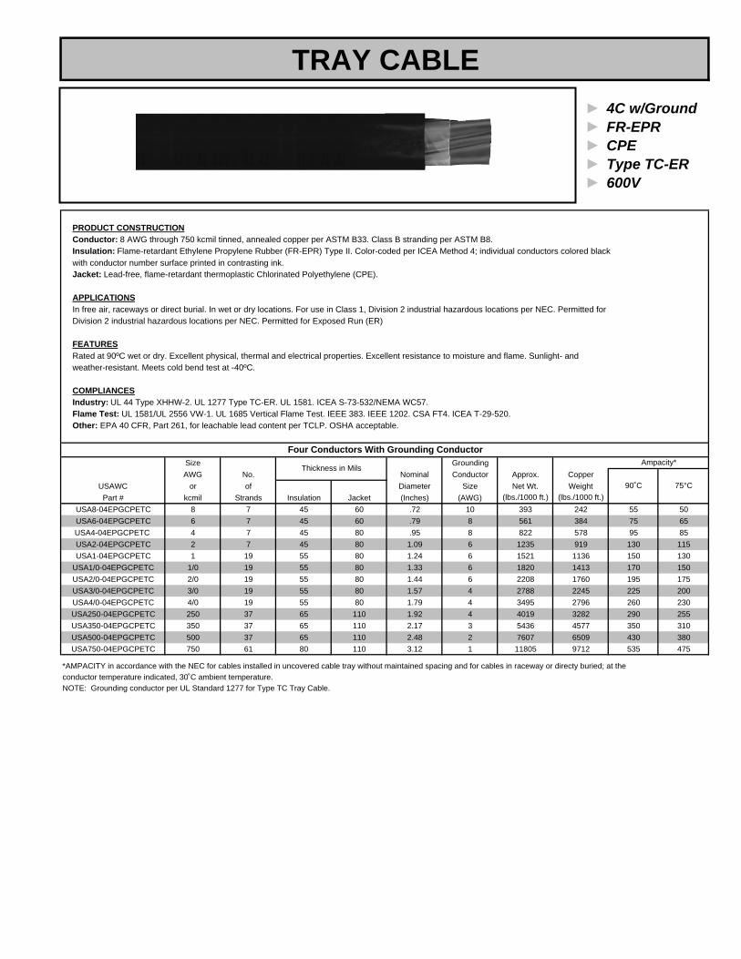
► 4C w/Ground► FR-EPR► CPE► Type TC-ER► 600V
PRODUCT CONSTRUCTIONConductor: 8 AWG through 750 kcmil tinned, annealed copper per ASTM B33. Class B stranding per ASTM B8.Insulation: Flame-retardant Ethylene Propylene Rubber (FR-EPR) Type II. Color-coded per ICEA Method 4; individual conductors colored blackwith conductor number surface printed in contrasting ink.Jacket: Lead-free, flame-retardant thermoplastic Chlorinated Polyethylene (CPE).
APPLICATIONSIn free air, raceways or direct burial. In wet or dry locations. For use in Class 1, Division 2 industrial hazardous locations per NEC. Permitted for Division 2 industrial hazardous locations per NEC. Permitted for Exposed Run (ER)
FEATURESRated at 90ºC wet or dry. Excellent physical, thermal and electrical properties. Excellent resistance to moisture and flame. Sunlight- and weather-resistant. Meets cold bend test at -40ºC.
COMPLIANCESIndustry: UL 44 Type XHHW-2. UL 1277 Type TC-ER. UL 1581. ICEA S-73-532/NEMA WC57.Flame Test: UL 1581/UL 2556 VW-1. UL 1685 Vertical Flame Test. IEEE 383. IEEE 1202. CSA FT4. ICEA T-29-520.Other: EPA 40 CFR, Part 261, for leachable lead content per TCLP. OSHA acceptable.
Size GroundingAWG No. Nominal Conductor Approx. Copper
USAWC or of Diameter Size Net Wt. WeightPart # kcmil Strands Insulation Jacket (Inches) (AWG) (lbs./1000 ft.) (lbs./1000 ft.)
USA8-04EPGCPETC 8 7 45 60 .72 10 393 242 55 50USA6-04EPGCPETC 6 7 45 60 .79 8 561 384 75 65USA4-04EPGCPETC 4 7 45 80 .95 8 822 578 95 85USA2-04EPGCPETC 2 7 45 80 1.09 6 1235 919 130 115USA1-04EPGCPETC 1 19 55 80 1.24 6 1521 1136 150 130
USA1/0-04EPGCPETC 1/0 19 55 80 1.33 6 1820 1413 170 150USA2/0-04EPGCPETC 2/0 19 55 80 1.44 6 2208 1760 195 175USA3/0-04EPGCPETC 3/0 19 55 80 1.57 4 2788 2245 225 200USA4/0-04EPGCPETC 4/0 19 55 80 1.79 4 3495 2796 260 230USA250-04EPGCPETC 250 37 65 110 1.92 4 4019 3282 290 255USA350-04EPGCPETC 350 37 65 110 2.17 3 5436 4577 350 310USA500-04EPGCPETC 500 37 65 110 2.48 2 7607 6509 430 380USA750-04EPGCPETC 750 61 80 110 3.12 1 11805 9712 535 475
NOTE: Grounding conductor per UL Standard 1277 for Type TC Tray Cable.conductor temperature indicated, 30˚C ambient temperature.
Four Conductors With Grounding Conductor
Thickness in Mils
90˚C
Ampacity*
75°C
*AMPACITY in accordance with the NEC for cables installed in uncovered cable tray without maintained spacing and for cables in raceway or directy buried; at the
TRAY CABLE

► Multi-Conductor► LS-XLP► LSZH► Type TC-ER► 600V
PRODUCT CONSTRUCTIONConductor: 14 AWG, 12 AWG or 10AWG stranded bare copper per ASTM B3. Class B stranding per ASTM B8.Insulation: Lead-free, flame-retardant, low-smoke, Cross-linked Polyethylene (XLP). Color-coded per ICEA Method 1, Table E-2 (does not include white or green).Jacket: Lead-free, flame-retardant, sunlight-resistant, Low-Smoke, Zero-Halogen Polyolefin (LSZH).
APPLICATIONSIn free air, raceways, aerial or direct burial. In wet or dry locations. Permitted for use in Class I, Division 2 industrial hazardous locations per NEC. Permitted for Exposedin Class I, Division 2 industrial hazardous locations per NEC. Permitted for Exposed Run (ER) use in accordance with the NEC for three or more conductors.
FEATURESRated at 90ºC wet or dry. Ripcord applied to all cables with jacket thickness of 60 mils or less. Excellent physical and electrical properties. Excellent moisture resistance.Excellent resistance to compression and impact. Chemical-resistant. Low coefficient of friction for easy pulling. Sunlight- and weather-resistant. Meets cold bendtest at -30ºC. Low-Smoke, Zero-Halogen jacket is is environmentally safe and reduces the amount of toxic and corrosive gases emitted during combustion.
COMPLIANCESIndustry: UL 44 Type XHHW-2. UL 1277 Type TC-LS-ER. UL 1581. ICEA S-73-532/NEMA WC57. ICEA T-33-655. RoHS compliant.Flame Test:UL 1581/UL 2556 VW-1. UL 1685 Vertical Flame Test. IEEE 1202/CSA FT4. Other: EPA 40 CFR, Part 261, for leachable lead content per TCLP. OSHA acceptable.
NominalNo. Cond. Insulation Jacket Cable Copper Net
USAWC of Size Cond. Thickness Thickness Diameter Weight WeightPart # Conductors (AWG) Strand (Inches) (Inches) (Inches) (lbs./1000 ft.) (lbs./1000 ft.)
USA14-02LSZHTCFL 2 flat 14 7 .030 .045 .365x.230 26 61USA14-02LSZHTC 2 14 7 .030 .045 .370 26 71USA14-03LSZHTC 3 14 7 .030 .045 .390 39 92
USA14-03WGLSZHTC 3+ Grnd 14 7 .030 .045 .410 53 105USA14-04LSZHTC 4 14 7 .030 .045 .425 53 115USA14-05LSZHTC 5 14 7 .030 .045 .465 66 139USA14-07LSZHTC 7 14 7 .030 .045 .505 92 173USA14-09LSZHTC 9 14 7 .030 .060 .620 118 240USA14-12LSZHTC 12 14 7 .030 .060 .700 158 301USA14-19LSZHTC 19 14 7 .030 .060 .815 250 468USA14-25LSZHTC 25 14 7 .030 .080 .935 323 624USA14-30LSZHTC 30 14 7 .030 .080 1.030 387 747USA14-37LSZHTC 37 14 7 .030 .080 1.110 466 875
USA12-02LSZHTCFL 2 FLAT 12 7 .030 .045 .400x.245 40 82USA12-02LSZHTC 2 12 7 .030 .045 .410 41 94USA12-03LSZHTC 3 12 7 .030 .045 .435 64 124
USA12-03WGLSZHTC 3+ Grnd 12 7 .030 .045 .410 85 148USA12-04LSZHTC 4 12 7 .030 .045 .475 85 157USA12-05LSZHTC 5 12 7 .030 .045 .520 106 191USA12-07LSZHTC 7 12 7 .030 .060 .595 149 268USA12-09LSZHTC 9 12 7 .030 .060 .695 191 337USA12-12LSZHTC 12 12 7 .030 .060 .765 247 428USA12-19LSZHTC 19 12 7 .030 .080 .940 391 688USA12-25LSZHTC 25 12 7 .030 .080 1.095 515 854USA12-30LSZHTC 30 12 7 .030 .080 1.150 618 1002USA12-37LSZHTC 37 12 7 .030 .080 1.240 762 1240
USA10-02LSZHTCFL 2 flat 10 7 .030 .045 .445x.270 64 113USA10-02LSZHTC 2 10 7 .030 .045 .455 65 128USA10-03LSZHTC 3 10 7 .030 .045 .485 100 172
USA10-03WGLSZHTC 3+ Grnd 10 7 .030 .045 .485 134 225USA10-04LSZHTC 4 10 7 .030 .060 .560 134 234USA10-05LSZHTC 5 10 7 .030 .060 .615 167 284USA10-07LSZHTC 7 10 7 .030 .060 .670 234 381USA10-09LSZHTC 9 10 7 .030 .060 .760 295 464USA10-12LSZHTC 12 10 7 .030 .080 .905 402 651
14 AWG Multi-Conductors
12 AWG Multi-Conductors
10 AWG Multi-Conductors
TRAY CABLE

► 3C w/Ground► LS-XLP► LZSH► Type TC-ER► 600V
PRODUCT CONSTRUCTIONConductor: 14 AWG through 750 kcmil bare annealed copper per ASTM B3. Class B stranding per ASTM B8.Insulation: Lead-free, flame-retardant, low-smoke, Cross-linked Polyethylene (XLPE). Color-coded per ICEA Method 4; individual conductors colored black with conductor number surface printed in contrasting ink.Jacket: Lead-free, flame-retardant, sunlight-resistant, Low-Smoke, Zero-Halogen Polyolefin (LSZH).
APPLICATIONSIn free air, raceways, aerial or direct burial. In wet or dry locations. Permitted for use in Class I, Division 2 industrial hazardous locations per NEC. Permitted for Exposed in Class I, Division 2 industrial hazardous locations per NEC. Permitted for Exposed Run (ER) use in accordance with the NEC.
FEATURESRated at 90ºC wet or dry. Ripcord applied to all cables with jacket thickness of 60 mils or less. Excellent physical and electrical properties. Excellent moisture resistance. Excellent resistance to compression and impact. Chemical-resistant. Low coefficient of friction for easy pulling. Sunlight- andweather-resistant. Meets cold bend test at -30ºC. Low-Smoke, Zero-Halogen jacket is is environmentally safe and reduces the amount of toxic and corrosive gases emitted during combustion.
COMPLIANCESIndustry: UL 44 Type XHHW-2. UL 1277 Type TC-LS-ER. UL 1581/UL 2556 VW-1. ICEA S-95-658/NEMA WC70. ICEA T-33-655. RoHS compliant.Flame Test:UL 1581/UL 2556 VW-1. UL 1685 Vertical Flame Test. IEEE 1202/CSA FT4. Other: EPA 40 CFR, Part 261, for leachable lead content per TCLP. OSHA acceptable.
Size Grounding(AWG No. Nominal Conductor Copper Net
USAWC or of Overall Diameter Size Weight WeightPart # kcmil) Strands Insulation Jacket (Inches) (AWG) (lbs./1000 ft.) (lbs./1000 ft.)
USA14-03WGLSZHTC 14 7 .030 .045 .430 14 55 118USA12-03WGLSZHTC 12 7 .030 .045 .480 12 87 160USA10-03WGLSZHTC 10 7 .030 .060 .565 10 136 237USA8-03WGLSZHTC 8 7 .045 .060 .655 10 190 314USA6-03WGLSZHTC 6 7 .045 .060 .740 8 297 456USA4-03WGLSZHTC 4 7 .045 .080 .880 8 442 642USA2-03WGLSZHTC 2 7 .045 .080 1.010 6 703 979USA1-03WGLSZHTC 1 19 .055 .080 1.120 6 872 1021
USA1/0-03WGLSZHTC 1/0 19 .055 .080 1.225 6 1069 1439USA2/0-03WGLSZHTC 2/0 19 .055 .080 1.300 6 1340 1720USA3/0-03WGLSZHTC 3/0 19 .055 .080 1.420 4 1717 2176USA4/0-03WGLSZHTC 4/0 19 .055 .080 1.540 4 2130 2614USA250-03WGLSZHTC 250 37 .065 .110 1.760 4 2494 3184USA350-03WGLSZHTC 350 37 .065 .110 1.960 3 3474 4187USA500-03WGLSZHTC 500 37 .065 .110 2.245 2 4934 5847USA750-03WGLSZHTC 750 61 .080 .140 2.810 1 7278 9145
Three Conductors With Grounding ConductorThickness in Inches
TRAY CABLE

► 4C w/Ground► LS-XLP► LZSH► Type TC-ER
PRODUCT CONSTRUCTIONConductor: 8 AWG through 750 kcmil bare annealed copper per ASTM B3. Class B stranding per ASTM B8.Insulation: Lead-free, flame-retardant, low-smoke, Cross-linked Polyethylene (XLPE). Color-coded per ICEA Method 4; individual conductors colored black with conductor number surface printed in contrasting ink.Jacket: Lead-free, flame-retardant, sunlight-resistant, Low-Smoke, Zero-Halogen Polyolefin (LSZH).
APPLICATIONSIn free air, raceways, aerial or direct burial. In wet or dry locations. Permitted for use in Class I, Division 2 industrial hazardous locations per NEC. Permitted for Exposed in Class I, Division 2 industrial hazardous locations per NEC. Permitted for Exposed Run (ER) use in accordance with the NEC.
FEATURESRated at 90ºC wet or dry. Ripcord applied to all cables with jacket thickness of 60 mils or less. Excellent physical and electrical properties. Excellent moisture resistance. Excellent resistance to compression and impact. Chemical-resistant. Low coefficient of friction for easy pulling. Sunlight- andweather-resistant. Meets cold bend test at -30ºC. Low-Smoke, Zero-Halogen jacket is is environmentally safe and reduces the amount of toxic and corrosive gases emitted during combustion.
COMPLIANCESIndustry: UL 44 Type XHHW-2. UL 1277 Type TC-LS-ER. UL 1581/UL 2556 VW-1. ICEA S-95-658/NEMA WC70. ICEA T-33-655. RoHS compliant.Flame Test:UL 1581/UL 2556 VW-1. UL 1685 Vertical Flame Test. IEEE 1202/CSA FT4. Other: EPA 40 CFR, Part 261, for leachable lead content per TCLP. OSHA acceptable.
Size Grounding(AWG No. Nominal Conductor Copper Net
USAWC or of Overall Diameter Size Weight WeightPart # kcmil) Strands Insulation Jacket (Inches) (AWG) (lbs./1000 ft.) (lbs./1000 ft.)
USA8-04WGLSZHTC 8 7 .045 .060 .720 10 242 393USA6-04WGLSZHTC 6 7 .045 .060 .790 8 384 561USA4-04WGLSZHTC 4 7 .045 .080 .950 8 578 822USA2-04WGLSZHTC 2 7 .045 .080 1.090 6 919 1235USA1-04WGLSZHTC 1 19 .055 .080 1.235 6 1136 1521
USA1/0-04WGLSZHTC 1/0 19 .055 .080 1.330 6 1413 1820USA2/0-04WGLSZHTC 2/0 19 .055 .080 1.440 6 1760 2208USA3/0-04WGLSZHTC 3/0 19 .055 .080 1.570 4 2245 2788USA4/0-04WGLSZHTC 4/0 19 .055 .110 1.790 4 2796 3495USA250-04WGLSZHTC 250 37 .065 .110 1.915 4 3282 4019USA350-04WGLSZHTC 350 37 .065 .110 2.165 3 4577 5436USA500-04WGLSZHTC 500 37 .065 .110 2.475 2 6509 7607USA750-04WGLSZHTC 750 61 .080 .140 3.115 1 9712 11805
► 600V
Four Conductors With Grounding ConductorThickness in Inches
TRAY CABLE
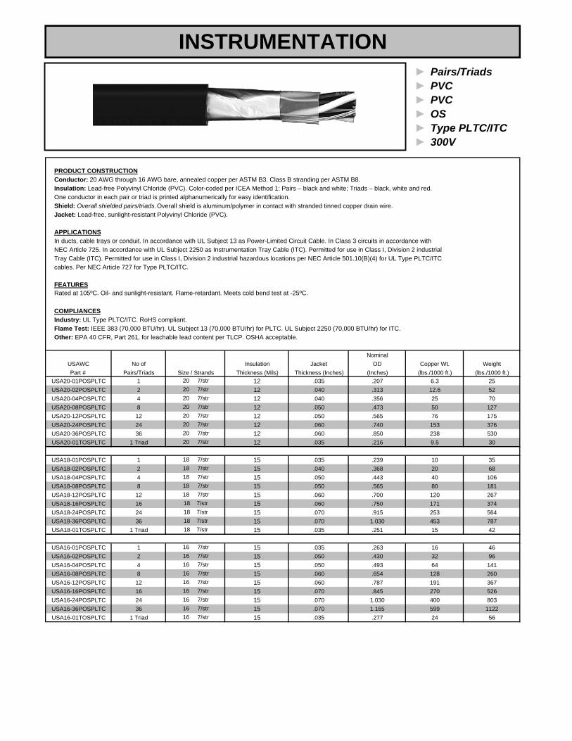
► Pairs/Triads► PVC► PVC► OS► Type PLTC/ITC► 300V
PRODUCT CONSTRUCTIONConductor: 20 AWG through 16 AWG bare, annealed copper per ASTM B3. Class B stranding per ASTM B8.Insulation: Lead-free Polyvinyl Chloride (PVC). Color-coded per ICEA Method 1: Pairs – black and white; Triads – black, white and red. One conductor in each pair or triad is printed alphanumerically for easy identification.Shield: Overall shielded pairs/triads.Overall shield is aluminum/polymer in contact with stranded tinned copper drain wire.Jacket: Lead-free, sunlight-resistant Polyvinyl Chloride (PVC).
APPLICATIONSIn ducts, cable trays or conduit. In accordance with UL Subject 13 as Power-Limited Circuit Cable. In Class 3 circuits in accordance withNEC Article 725. In accordance with UL Subject 2250 as Instrumentation Tray Cable (ITC). Permitted for use in Class I, Division 2 industrialTray Cable (ITC). Permitted for use in Class I, Division 2 industrial hazardous locations per NEC Article 501.10(B)(4) for UL Type PLTC/ITCcables. Per NEC Article 727 for Type PLTC/ITC.
FEATURESRated at 105ºC. Oil- and sunlight-resistant. Flame-retardant. Meets cold bend test at -25ºC.
COMPLIANCESIndustry: UL Type PLTC/ITC. RoHS compliant.Flame Test: IEEE 383 (70,000 BTU/hr). UL Subject 13 (70,000 BTU/hr) for PLTC. UL Subject 2250 (70,000 BTU/hr) for ITC.Other: EPA 40 CFR, Part 261, for leachable lead content per TLCP. OSHA acceptable.
NominalUSAWC No of Insulation Jacket OD Copper Wt. WeightPart # Pairs/Triads Thickness (Mils) Thickness (Inches) (Inches) (lbs./1000 ft.) (lbs./1000 ft.)
USA20-01POSPLTC 1 12 .035 .207 6.3 25USA20-02POSPLTC 2 12 .040 .313 12.6 52USA20-04POSPLTC 4 12 .040 .356 25 70USA20-08POSPLTC 8 12 .050 .473 50 127USA20-12POSPLTC 12 12 .050 .565 76 175USA20-24POSPLTC 24 12 .060 .740 153 376USA20-36POSPLTC 36 12 .060 .850 238 530USA20-01TOSPLTC 1 Triad 12 .035 .216 9.5 30
USA18-01POSPLTC 1 15 .035 .239 10 35USA18-02POSPLTC 2 15 .040 .368 20 68USA18-04POSPLTC 4 15 .050 .443 40 106USA18-08POSPLTC 8 15 .050 .565 80 181USA18-12POSPLTC 12 15 .060 .700 120 267USA18-16POSPLTC 16 15 .060 .750 171 374USA18-24POSPLTC 24 15 .070 .915 253 564USA18-36POSPLTC 36 15 .070 1.030 453 787USA18-01TOSPLTC 1 Triad 15 .035 .251 15 42
USA16-01POSPLTC 1 15 .035 .263 16 46USA16-02POSPLTC 2 15 .050 .430 32 96USA16-04POSPLTC 4 15 .050 .493 64 141USA16-08POSPLTC 8 15 .060 .654 128 260USA16-12POSPLTC 12 15 .060 .787 191 367USA16-16POSPLTC 16 15 .070 .845 270 526USA16-24POSPLTC 24 15 .070 1.030 400 803USA16-36POSPLTC 36 15 .070 1.165 599 1122USA16-01TOSPLTC 1 Triad 15 .035 .277 24 56
18 7/str
16 7/str
16 7/str16 7/str
16 7/str
16 7/str16 7/str
16 7/str16 7/str
20 7/str20 7/str
16 7/str
18 7/str
18 7/str
20 7/str
18 7/str18 7/str
18 7/str
20 7/str
18 7/str
Size / Strands
20 7/str20 7/str
20 7/str20 7/str
18 7/str18 7/str
INSTRUMENTATION
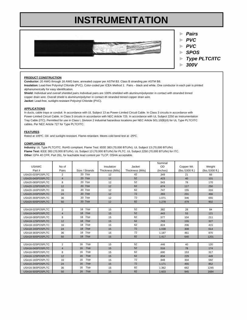
► Pairs► PVC► PVC► SPOS► Type PLTC/ITC► 300V
PRODUCT CONSTRUCTIONConductor: 20 AWG through 16 AWG bare, annealed copper per ASTM B3. Class B stranding per ASTM B8.Insulation: Lead-free Polyvinyl Chloride (PVC). Color-coded per ICEA Method 1: Pairs – black and white. One conductor in each pair is printedalphanumerically for easy identification.Shield: Individual and overall shielded pairs. Individual pairs are 100% shielded with aluminum/polyester in contact with stranded tinnedcopper drain wire. Overall shield is aluminum/polymer in contact ith stranded tinned copper drain wire.Jacket: Lead-free, sunlight-resistant Polyvinyl Chloride (PVC).
APPLICATIONSIn ducts, cable trays or conduit. In accordance with UL Subject 13 as Power-Limited Circuit Cable. In Class 3 circuits in accordance withPower-Limited Circuit Cable. In Class 3 circuits in accordance with NEC Article 725. In accordance with UL Subject 2250 as InstrumentationTray Cable (ITC). Permitted for use in Class I, Division 2 industrial hazardous locations per NEC Article 501.10(B)(4) for UL Type PLTC/ITCcables. Per NEC Article 727 for Type PLTC/ITC.
FEATURESRated at 105ºC. Oil- and sunlight-resistant. Flame-retardant. Meets cold bend test at -25ºC.
COMPLIANCESIndustry: UL Type PLTC/ITC. RoHS compliant. Flame Test: IEEE 383 (70,000 BTU/hr). UL Subject 13 (70,000 BTU/hr)Flame Test: IEEE 383 (70,000 BTU/hr). UL Subject 13 (70,000 BTU/hr) for PLTC. UL Subject 2250 (70,000 BTU/hr) for ITC.Other: EPA 40 CFR, Part 261, for leachable lead content per TLCP. OSHA acceptable.
NominalUSAWC No of Insulation OD Copper Wt. Weight
Part # Pairs Thickness (Mils) (Inches) (lbs./1000 ft.) (lbs./1000 ft.)USA20-02SPOSPLTC 2 12 .349 21 66USA20-04SPOSPLTC 4 12 .423 40 101USA20-08SPOSPLTC 8 12 .543 78 170USA20-12SPOSPLTC 12 12 .674 117 250USA20-16SPOSPLTC 16 12 .747 155 316USA20-24SPOSPLTC 24 12 .393 231 466USA20-36SPOSPLTC 36 12 1.071 346 655USA20-50SPOSPLTC 50 12 1.278 479 902
USA18-02SPOSPLTC 2 15 .382 28 84USA18-04SPOSPLTC 4 15 .443 53 121USA18-08SPOSPLTC 8 15 .577 104 211USA18-12SPOSPLTC 12 15 .743 155 327USA18-16SPOSPLTC 16 15 .824 206 415USA18-24SPOSPLTC 24 15 1.038 308 614USA18-36SPOSPLTC 36 15 1.187 461 870USA18-50SPOSPLTC 50 15 1.417 640 1201
USA16-02SPOSPLTC 2 15 .446 40 120USA16-04SPOSPLTC 4 15 .516 78 174USA16-08SPOSPLTC 8 15 .690 153 317USA16-12SPOSPLTC 12 15 .834 229 449USA16-16SPOSPLTC 16 15 .948 304 592USA16-24SPOSPLTC 24 15 1.171 455 852USA16-36SPOSPLTC 36 15 1.362 662 1245USA16-50SPOSPLTC 50 15 1.603 945 1684
18 7/str18 7/str
72
62
82
52
6216 7/str16 7/str
7272
62
18 7/str18 7/str
20 7/str 62
20 7/str 8220 7/str 7220 7/str 72
4220 7/str 52
62
18 7/str
20 7/str 52
18 7/str
20 7/str 62
18 7/str
16 7/str16 7/str16 7/str
16 7/str
16 7/str16 7/str
82
7282
Size / StrandsJacket
Thickness (Mils)
525262
52
18 7/str
20 7/str
INSTRUMENTATION

► Triads► PVC► PVC► STOS► Type PLTC/ITC► 300V
PRODUCT CONSTRUCTIONConductor: 20 AWG through 16 AWG bare, annealed copper per ASTM B3. Class B stranding per ASTM B8.Insulation: Lead-free Polyvinyl Chloride (PVC). Color-coded per ICEA Method 1: Triads – black, white and red. One conductor in each triad is printedalphanumerically for easy identification.Shield: Individual and overall shielded triads. Individual triads are 100% shielded with aluminum/polyester in contact with stranded tinnedcopper drain wire. Overall shield is aluminum/polymer in contact ith stranded tinned copper drain wire.Jacket: Lead-free, sunlight-resistant Polyvinyl Chloride (PVC).
APPLICATIONSIn ducts, cable trays or conduit. In accordance with UL Subject 13 as Power-Limited Circuit Cable. In Class 3 circuits in accordance withPower-Limited Circuit Cable. In Class 3 circuits in accordance with NEC Article 725. In accordance with UL Subject 2250 as InstrumentationTray Cable (ITC). Permitted for use in Class I, Division 2 industrial hazardous locations per NEC Article 501.10(B)(4) for UL Type PLTC/ITCcables. Per NEC Article 727 for Type PLTC/ITC.
FEATURESRated at 105ºC. Oil- and sunlight-resistant. Flame-retardant. Meets cold bend test at -25ºC.
COMPLIANCESIndustry: UL Type PLTC/ITC. RoHS compliant. Flame Test: IEEE 383 (70,000 BTU/hr). UL Subject 13 (70,000 BTU/hr)Flame Test: IEEE 383 (70,000 BTU/hr). UL Subject 13 (70,000 BTU/hr) for PLTC. UL Subject 2250 (70,000 BTU/hr) for ITC.Other: EPA 40 CFR, Part 261, for leachable lead content per TLCP. OSHA acceptable.
NominalUSAWC No of Insulation OD Copper Wt. WeightPart # Triads Thickness (Mils) (Inches) (lbs./1000 ft.) (lbs./1000 ft.)
USA20-02STOSPLTC 2 12 .357 26 77USA20-04STOSPLTC 4 12 .433 48 122USA20-08STOSPLTC 8 12 .556 97 212USA20-12STOSPLTC 12 12 .690 145 313USA20-16STOSPLTC 16 12 .765 192 399USA20-24STOSPLTC 24 12 .963 288 591
USA18-02STOSPLTC 2 15 .431 38 108USA18-04STOSPLTC 4 15 .476 73 160USA18-08STOSPLTC 8 15 .635 147 293USA18-12STOSPLTC 12 15 .764 215 416USA18-16STOSPLTC 16 15 .849 286 533USA18-24STOSPLTC 24 15 1.070 428 793
USA16-02STOSPLTC 2 15 .460 54 146USA16-04STOSPLTC 4 15 .533 108 221USA16-08STOSPLTC 8 15 .713 218 410USA16-12STOSPLTC 12 15 .863 325 587USA16-16STOSPLTC 16 15 .981 433 777USA16-24STOSPLTC 24 15 1.212 649 1130
JacketThickness (Mils)
5252
62
42
62
5252
72
62
6216 7/str
6218 7/str
18 7/str
18 7/str6272
18 7/str
7216 7/str
5216 7/str
16 7/str6272
16 7/str
5216 7/str
Size / Strands
18 7/str
20 7/str
20 7/str20 7/str20 7/str
20 7/str20 7/str
18 7/str
INSTRUMENTATION

► Pairs► PVC/Nylon► PVC► SPOS► Type TC-ER► 600V
PRODUCT CONSTRUCTIONConductor: 18 AWG and 16 AWG bare, annealed copper per ASTM B3. Class B stranding per ASTM B8.Insulation: Flame-retardant Polyvinyl Chloride (PVC) with clear Polyamide (nylon). Color-coded per ICEA Method 1: Pairs – black and white. One conductor in each pair is printed alphanumerically for easy identification.Shield: Individual and overall shielded pairs. Individual triads are 100% shielded with aluminum/polyester in contact with stranded tinnedcopper drain wire. Overall shield is aluminum/polymer in contact ith stranded tinned copper drain wire.Jacket: Lead-free, sunlight-resistant Polyvinyl Chloride (PVC).
APPLICATIONSIn free air, raceways or direct burial. In wet or dry locations. Permitted for use in Class I, Division 2 industrial hazardous locations per NEC.
FEATURESRated at 90ºC dry, 75ºC wet. Ripcord applied to all cables with jacket thickness of 60 mils or less. Provides sunlight, cold bend and coldimpact resistance. Offers the smallest cable O.D. available for suitable applications. Provides excellent oil and chemical resistance. Meets cold bend test at -25º C.
COMPLIANCESIndustry: UL 1277 Type TC. UL 1581. NEC Type TFN conductors. ICEA S-73-532/NEMA WC57.Flame Test: UL 1685 Vertical Flame Test. IEEE 383. IEEE 1202. CSA FT4.Other: EPA 40 CFR, Part 261, for leachable lead content per TCLP. OSHA acceptable. RoHS compliant.
Insulation Jacket Nominal Copper Approx.USAWC No. of Size Thickness (Mils) Thickness OD Weight Net Wt.Part # Pairs Strands (PVC/Nylon) (Mils) (Inches) (lbs./1000 ft.) (lbs./1000 ft.)
USA18-02SPOSVNTC 2 18 7/Str 15/4 47 .429 30 96USA18-04SPOSVNTC 4 18 7/Str 15/4 47 .498 55 139USA18-08SPOSVNTC 8 18 7/Str 15/4 62 .678 105 257USA18-12SPOSVNTC 12 18 7/Str 15/4 62 .819 156 359USA18-16SPOSVNTC 16 18 7/Str 15/4 82 .951 207 490USA18-24SPOSVNTC 24 18 7/Str 15/4 82 1.169 302 695USA18-36SPOSVNTC 36 18 7/Str 15/4 82 1.336 452 987USA18-50SPOSVNTC 50 18 7/Str 15/4 82 1.572 628 1314
USA16-02SPOSVNTC 2 16 7/Str 15/4 47 .480 42 127USA16-03SPOSVNTC 3 16 7/Str 15/4 47 .514 61 145USA16-04SPOSVNTC 4 16 7/Str 15/4 62 .590 80 207USA16-06SPOSVNTC 6 16 7/Str 15/4 62 .694 116 270USA16-08SPOSVNTC 8 16 7/Str 15/4 62 .763 155 344USA16-12SPOSVNTC 12 16 7/Str 15/4 82 .966 230 521USA16-16SPOSVNTC 16 16 7/Str 15/4 82 1.072 306 660USA16-24SPOSVNTC 24 16 7/Str 15/4 82 1.323 456 944USA16-36SPOSVNTC 36 16 7/Str 15/4 92 1.536 674 1370USA16-50SPOSVNTC 50 16 7/Str 15/4 112 1.849 935 1914
INSTRUMENTATION TRAY CABLE Type TC (POS/TOS)INSTRUMENT WIRE 600 VOLT TC
Insulation Jacket Nominal Copper Approx.USAWC No. of Size Thickness (Mils) Thickness OD Weight Net Wt.Part # Pairs/Triads Strands (PVC/Nylon) (Mils) (Inches) (lbs./1000 ft.) (lbs./1000 ft.)
USA18-01POSVNTC 1 Pair 18 7/Str 15/4 47 .270 12 42USA16-01POSVNTC 1 Pair 16 7/Str 15/4 47 .294 18 55
USA18-01TOSVNTC 1 Triad 18 7/Str 15/4 47 .283 18 51USA16-01TOSVNTC 1 Triad 16 7/Str 15/4 47 .309 27 68
Note: Standard color coding is Method E-1 for NEC applications per ICEA; Pairs – black and white. Triads – black, white and red. One conductor in each pair isprinted alphanumerically.
INSTRUMENTATION

► Triads► PVC/Nylon► PVC► STOS► Type TC-ER► 600V
PRODUCT CONSTRUCTIONConductor: 18 AWG and 16 AWG bare, annealed copper per ASTM B3. Class B stranding per ASTM B8.Insulation: Flame-retardant Polyvinyl Chloride (PVC) with clear Polyamide (nylon). Color-coded per ICEA Method 1: Triads – black, white and red. One conductor in each triad is printed alphanumerically for easy identification.Shield: Individual and overall shielded triads. Individual triads are 100% shielded with aluminum/polyester in contact with stranded tinned copper drain wire. Overall shield is aluminum/polymer in contact with stranded tinned copper drain wire. Jacket: Lead-free, flame-retardant, sunlight-resistant Polyvinyl Chloride (PVC).
APPLICATIONSIn free air, raceways or direct burial. In wet or dry locations. Permitted for use in Class I, Division 2 industrial hazardous locations per NEC.
FEATURESRated at 90ºC dry, 75ºC wet. Ripcord applied to all cables with jacket thickness of 60 mils or less. Provides sunlight, cold bend and coldimpact resistance. Offers the smallest cable O.D. available for suitable applications. Provides excellent oil and chemical resistance. Meets cold bend test at -25º C.
COMPLIANCESIndustry: UL 1277 Type TC. UL 1581. NEC Type TFN conductors. ICEA S-73-532/NEMA WC57.Flame Test: UL 1685 Vertical Flame Test. IEEE 383. IEEE 1202. CSA FT4.Other: EPA 40 CFR, Part 261, for leachable lead content per TCLP. OSHA acceptable. RoHS compliant.
InsulationThickness Jacket Nominal Copper Approx.
USAWC No. of Size (Mils) Thickness OD Weight Net Wt.Part # Triads Strands (PVC/Nylon) (Mils) (Inches) (lbs./1000 ft.) (lbs./1000 ft.)
USA18-02STOSVNTC 2 18 7/Str 15/4 47 .453 38 117USA18-04STOSVNTC 4 18 7/Str 15/4 62 .557 73 190USA18-08STOSVNTC 8 18 7/Str 15/4 62 .718 144 327USA18-12STOSVNTC 12 18 7/Str 15/4 82 .909 218 495USA18-16STOSVNTC 16 18 7/Str 15/4 82 1.008 290 628USA18-24STOSVNTC 24 18 7/Str 15/4 82 1.242 433 899USA18-36STOSVNTC 36 18 7/Str 15/4 82 1.421 649 1279
USA16-02STOSVNTC 2 16 7/Str 15/4 47 .509 57 156USA16-04STOSVNTC 4 16 7/Str 15/4 62 .624 108 253USA16-08STOSVNTC 8 16 7/Str 15/4 62 .810 217 444USA16-12STOSVNTC 12 16 7/Str 15/4 82 1.024 328 671USA16-16STOSVNTC 16 16 7/Str 15/4 82 1.138 436 858USA16-24STOSVNTC 24 16 7/Str 15/4 82 1.408 653 1238USA16-36STOSVNTC 36 16 7/Str 15/4 82 1.615 979 1777
INSTRUMENTATION

► Pairs/Triads► FR-EPR► CPE► OS► Type TC-ER► 600V
PRODUCT CONSTRUCTIONConductor: 18 AWG and 16 AWG tinned, annealed copper per ASTM B33. Class B stranding per ASTM B8.Insulation: Flame-retardant Ethylene Propylene Rubber (FR-EPR) Type II. Color-coded per ICEA Method 1: Pairs – black and white; Triads – black,white and red. One conductor in each pair is printed alphanumerically for easy identification.Shield: Overall shielded pairs/triads.Overall shield is aluminum/polymer in contact with stranded tinned copper drain wire.Jacket: Lead-free, flame-retardant, thermoplastic Chlorinated Polyethylene (CPE).
APPLICATIONSIn free air, raceways or direct burial. In wet or dry locations. Permitted for use in Class I, Division 2 industrial hazardous locations per NEC.
FEATURESRated at 90ºC wet or dry. Ripcord applied to all cables with jacket thickness of 60 mils or less. Excellent physical, thermal and electricaproperties. Excellent moisture resistence. Excellent resistance to compression cuts and heat deformation. Excellent flame resistance –burns to an ash; does not exhibit thermoplastic drip. Low coefficient of friction for easy pulling. Sunlight- and weather-resistant. Excellentlow temperature cold bend characteristics. Meets cold bend test at -40ºC.
COMPLIANCESIndustry: UL 1277 Type TC. UL 1581. ICEA S-73-532/NEMA WC57.Flame Test: UL 1581/UL 2556 VW-1. UL 1685 Vertical Flame Test. IEEE 383. IEEE 1202. CSA FT4. ICEA T-29-520.Other: EPA 40 CFR, Part 261, for leachable lead content per TCLP. OSHA acceptable.
NominalUSAWC No of Insulation Jacket OD Copper Weight Net WeightPart # Pairs/Triads Size / Strands Thickness (Inches) Thickness (Inches) (Inches) (lbs./1000 ft.) (lbs./1000 ft.)
USA18-01POSECPETC 1 18 / 7 str .025 .045 .300 13 42USA18-01TOSECPETC 1 TRI 18 / 7 str .025 .045 .315 18 53
USA16-01POSECPETC 1 16 / 7 str .025 .045 .320 18 52USA16-01TOSECPETC 1 TRI 16 / 7 str .025 .045 .335 26 66
INSTRUMENTATION

► Pairs► FR-EPR► CPE► SPOS► Type TC-ER► 600V
PRODUCT CONSTRUCTION
Conductor: 18 AWG and 16 AWG tinned, annealed copper per ASTM B33. Class B stranding per ASTM B8.Insulation: Flame-retardant Ethylene Propylene Rubber (FR-EPR) Type II. Color-coded per ICEA Method 1: Pairs – black and white. One conductorin each pair is printed alphanumerically for easy identification.Shield: Individual and overall shielded pairs. Individual pairs are 100% shielded with aluminum/polyester in contact with stranded tinned copperdrain wire. Overall shield is aluminum/polymer in contact with stranded tinned copper drain wire.Jacket: Lead-free, flame-retardant, thermoplastic Chlorinated Polyethylene (CPE).
APPLICATIONSIn free air, raceways or direct burial. In wet or dry locations. Permitted for use in Class I, Division 2 industrial hazardous locations per NEC.
FEATURESRated at 90ºC wet or dry. Ripcord applied to all cables with jacket thickness of 60 mils or less. Excellent physical, thermal and electricaproperties. Excellent moisture resistence. Excellent resistance to compression cuts and heat deformation. Excellent flame resistance –burns to an ash; does not exhibit thermoplastic drip. Low coefficient of friction for easy pulling. Sunlight- and weather-resistant. Excellentlow temperature cold bend characteristics. Meets cold bend test at -40ºC.
COMPLIANCESIndustry: UL 1277 Type TC. UL 1581. ICEA S-73-532/NEMA WC57.Flame Test: UL 1581/UL 2556 VW-1. UL 1685 Vertical Flame Test. IEEE 383. IEEE 1202. CSA FT4. ICEA T-29-520.Other: EPA 40 CFR Part 261 for leachable lead content per TCLP OSHA acceptable
INSTRUMENTATION
Other: EPA 40 CFR, Part 261, for leachable lead content per TCLP. OSHA acceptable.
Insulation Nominal Copper Approx.USAWC No. of Size Thickness OD Net Wt. Net Wt.Part # Pairs Strands (Inches) (Inches) (lbs./1000 ft.) (lbs./1000 ft.)
USA18-02SPOSECPETC 2 18 7/Str .025 .473 27 83USA18-04SPOSECPETC 4 18 7/Str .025 .586 53 152USA18-08SPOSECPETC 8 18 7/Str .025 .751 103 259USA18-12SPOSECPETC 12 18 7/Str .025 .948 153 398USA18-16SPOSECPETC 16 18 7/Str .025 1.050 206 502USA18-24SPOSECPETC 24 18 7/Str .025 1.220 311 709USA18-36SPOSECPETC 36 18 7/Str .025 1.474 461 1008USA18-50SPOSECPETC 50 18 7/Str .025 1.780 640 1454
USA16-02SPOSECPETC 2 16 7/Str .025 .500 40 103USA16-04SPOSECPETC 4 16 7/Str .025 .650 77 189USA16-06SPOSECPETC 6 16 7/Str .025 .755 115 268USA16-08SPOSECPETC 8 16 7/Str .025 .840 151 330USA16-12SPOSECPETC 12 16 7/Str .025 1.065 226 506USA16-16SPOSECPETC 16 16 7/Str .025 1.185 305 643USA16-24SPOSECPETC 24 16 7/Str .025 1.485 455 932USA16-36SPOSECPETC 36 16 7/Str .025 1.760 683 1410USA16-50SPOSECPETC 50 16 7/Str .025 2.035 946 1883
.060
.110
.060
.080
.080
.060
.080
.080
JacketThickness(Inches)
.045
.080
.060
.110
.060
.080
.045
.080
.080
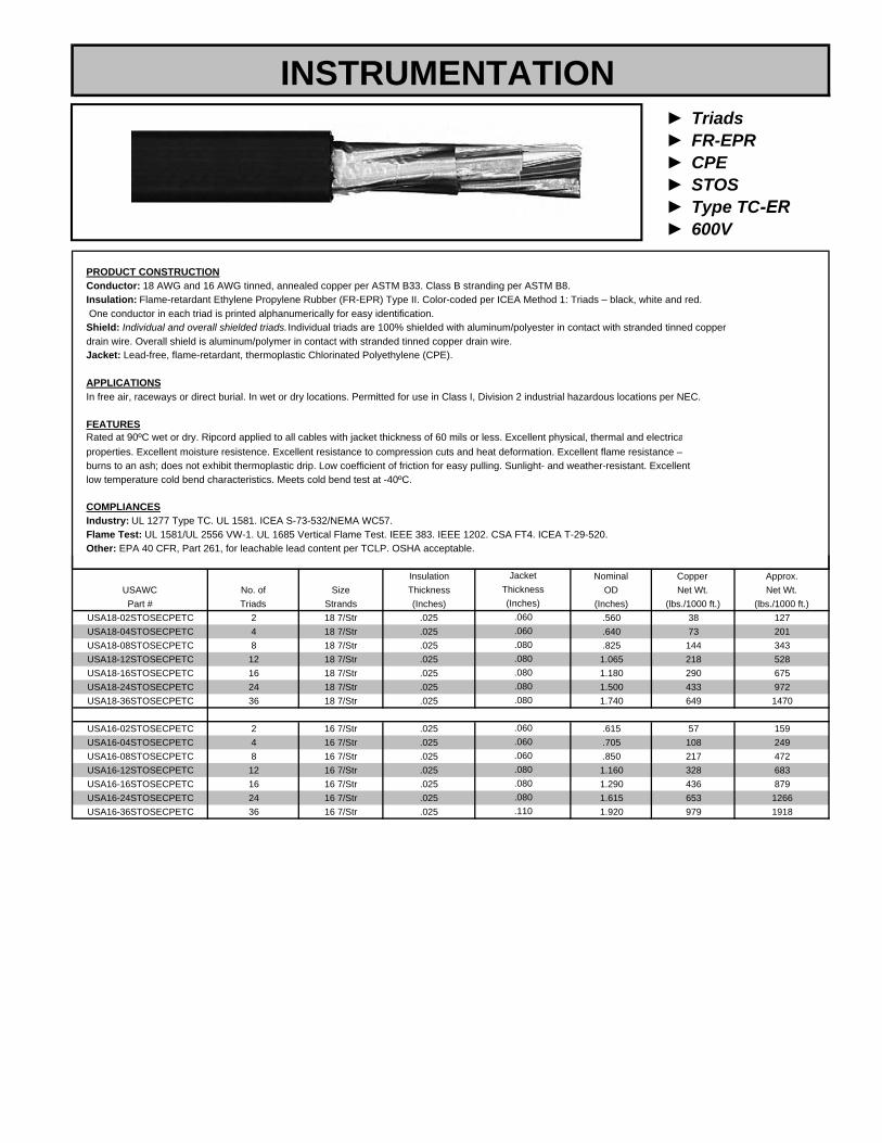
► Triads► FR-EPR► CPE► STOS► Type TC-ER► 600V
PRODUCT CONSTRUCTIONConductor: 18 AWG and 16 AWG tinned, annealed copper per ASTM B33. Class B stranding per ASTM B8.Insulation: Flame-retardant Ethylene Propylene Rubber (FR-EPR) Type II. Color-coded per ICEA Method 1: Triads – black, white and red. One conductor in each triad is printed alphanumerically for easy identification.Shield: Individual and overall shielded triads. Individual triads are 100% shielded with aluminum/polyester in contact with stranded tinned copperdrain wire. Overall shield is aluminum/polymer in contact with stranded tinned copper drain wire.Jacket: Lead-free, flame-retardant, thermoplastic Chlorinated Polyethylene (CPE).
APPLICATIONSIn free air, raceways or direct burial. In wet or dry locations. Permitted for use in Class I, Division 2 industrial hazardous locations per NEC.
FEATURESRated at 90ºC wet or dry. Ripcord applied to all cables with jacket thickness of 60 mils or less. Excellent physical, thermal and electricaproperties. Excellent moisture resistence. Excellent resistance to compression cuts and heat deformation. Excellent flame resistance –burns to an ash; does not exhibit thermoplastic drip. Low coefficient of friction for easy pulling. Sunlight- and weather-resistant. Excellentlow temperature cold bend characteristics. Meets cold bend test at -40ºC.
COMPLIANCESIndustry: UL 1277 Type TC. UL 1581. ICEA S-73-532/NEMA WC57.Flame Test: UL 1581/UL 2556 VW-1. UL 1685 Vertical Flame Test. IEEE 383. IEEE 1202. CSA FT4. ICEA T-29-520.Other: EPA 40 CFR, Part 261, for leachable lead content per TCLP. OSHA acceptable.
INSTRUMENTATION
Insulation Nominal Copper Approx.USAWC No. of Size Thickness OD Net Wt. Net Wt.Part # Triads Strands (Inches) (Inches) (lbs./1000 ft.) (lbs./1000 ft.)
USA18-02STOSECPETC 2 18 7/Str .025 .560 38 127USA18-04STOSECPETC 4 18 7/Str .025 .640 73 201USA18-08STOSECPETC 8 18 7/Str .025 .825 144 343USA18-12STOSECPETC 12 18 7/Str .025 1.065 218 528USA18-16STOSECPETC 16 18 7/Str .025 1.180 290 675USA18-24STOSECPETC 24 18 7/Str .025 1.500 433 972USA18-36STOSECPETC 36 18 7/Str .025 1.740 649 1470
USA16-02STOSECPETC 2 16 7/Str .025 .615 57 159USA16-04STOSECPETC 4 16 7/Str .025 .705 108 249USA16-08STOSECPETC 8 16 7/Str .025 .850 217 472USA16-12STOSECPETC 12 16 7/Str .025 1.160 328 683USA16-16STOSECPETC 16 16 7/Str .025 1.290 436 879USA16-24STOSECPETC 24 16 7/Str .025 1.615 653 1266USA16-36STOSECPETC 36 16 7/Str .025 1.920 979 1918
.080
.080
.110
.060
.080
.080
.060
.060
.080
(Inches).060.060
JacketThickness
.080
.080
.080

► Pairs/Triads► LS-XLP► LSZH► OS► Type TC► 600V
PRODUCT CONSTRUCTIONConductor: 18 AWG and 16 AWG tinned, annealed copper per ASTM B33. Class B stranding per ASTM B8.Insulation: Lead-free, flame-retardant, low-smoke, Cross-Linked Polyethylene (XLPE). Color-coded per ICEA Method 1: Pairs – black and white. Triads – black, white and red. One conductor in each pair or triad is printed alphanumerically for easy identification.Shield: Overall shielded pairs/triads. Overall shield is aluminum/polymer in contact with stranded tinned copper drain wire.Jacket: Lead-free, flame-retardant, sunlight-resistant, Low-Smoke, Zero-Halogen Polyolefin (LSZH).
APPLICATIONSIn free air, raceways or direct burial. In wet or dry locations. Permitted for use in Class I, Division 2 industrial hazardous locations per NEC.
FEATURESRated at 90ºC wet or dry. Ripcord applied to all cables with jacket thickness of 60 mils or less. Excellent physical and electrical properties. Excellent moisture resistence. Excellent resistance to compression and impact. Chemical-resistant. Low coefficient of friction for easy pulling. Sunlight- and weather-resistant. Meets cold bend test at -30ºC. Low-Smoke, Zero-Halogen jacket is environmentally safe and reduces the amount of toxic and corrosivegases emitted during combustion.
COMPLIANCESIndustry: UL 1277 Type TC-LS. UL 1581. ICEA S-73-532/NEMA WC57. ICEA T-33-655. RoHS compliant.Flame Test: UL 1581/UL 2556 VW-1. UL 1685 Vertical Flame Test. IEEE 383. IEEE 1202. CSA FT4. ICEA T-29-520.Other: EPA 40 CFR, Part 261, for leachable lead content per TCLP. OSHA acceptable.
Insulation Nominal Copper Approx.USAWC No. of Size Thickness OD Weight Net Wt.
Part # Pairs/Triads Strands (Inches) (Inches) (lbs./1000 ft.) (lbs./1000 ft.)
JacketThickness (Inches)
INSTRUMENTATION
Part # Pairs/Triads Strands (Inches) (Inches) (lbs./1000 ft.) (lbs./1000 ft.)USA18-01POSLSZHTC 1 18 7/Str .030 .315 13 46USA18-01TOSLSZHTC 1 TRI 18 7/Str .030 .340 18 58
USA16-01POSLSZHTC 1 16 7/Str .030 .345 18 32USA16-01TOSLSZHTC 1 TRI 16 7/Str .030 .360 26 72
Note: Standard color coding is Method E-1 for NEC applications per ICEA; Pairs – black and white. Triads – black, white and red. One conductor in each pair or triad is printed alphanumerically.
.045
.045
(Inches).045.045

► Pairs► LS-XLP► LSZH► SPOS► Type TC► 600V
PRODUCT CONSTRUCTIONConductor: 18 AWG and 16 AWG tinned, annealed copper per ASTM B33. Class B stranding per ASTM B8.Insulation: Lead-free, flame-retardant, low-smoke, Cross-Linked Polyethylene (XLPE). Color-coded per ICEA Method 1: Pairs – black and white. One conductor in each pair is printed alphanumerically for easy identification.Shield: Individual and overall shielded pairs. Individual pairs are 100% individually shielded with aluminum/polyester in contact with stranded tinnedcopper drain wire. Overall shield is aluminum/polymer in contact with stranded tinned copper drain wire.Jacket: Lead-free, flame-retardant, sunlight-resistant, Low-Smoke, Zero-Halogen Polyolefin (LSZH).
APPLICATIONSIn free air, raceways or direct burial. In wet or dry locations. Permitted for use in Class I, Division 2 industrial hazardous locations per NEC.
FEATURESRated at 90ºC wet or dry. Ripcord applied to all cables with jacket thickness of 60 mils or less. Excellent physical and electrical properties. Excellentmoisture resistence. Excellent resistance to compression and impact. Chemical-resistant. Low coefficient of friction for easy pulling. Sunlight- and weather-resistant. Meets cold bend test at -30ºC. Low-Smoke, Zero-Halogen jacket is environmentally safe and reduces the amount of toxic andcorrosive gases emitted during combustion.
COMPLIANCESIndustry: UL 1277 Type TC-LS. UL 1581. ICEA S-73-532/NEMA WC57. ICEA T-33-655. RoHS compliant.Flame Test: UL 1581/UL 2556 VW-1. UL 1685 Vertical Flame Test. IEEE 383. IEEE 1202. CSA FT4. ICEA T-29-520.Other: EPA 40 CFR, Part 261, for leachable lead content per TCLP. OSHA acceptable.
INSTRUMENTATION
Insulation Nominal Copper Approx.USAWC No. of Size Thickness OD Weight Net Wt.Part # Pairs Strands (Inches) (Inches) (lbs./1000 ft.) (lbs./1000 ft.)
USA18-02SPOSLSZHTC 2 18 7/Str .030 .510 27 92USA18-04SPOSLSZHTC 4 18 7/Str .030 .630 53 167USA18-08SPOSLSZHTC 8 18 7/Str .030 .855 103 326USA18-12SPOSLSZHTC 12 18 7/Str .030 1.030 153 441USA18-16SPOSLSZHTC 16 18 7/Str .030 1.140 206 554USA18-24SPOSLSZHTC 24 18 7/Str .030 1.450 311 795USA18-36SPOSLSZHTC 36 18 7/Str .030 1.650 461 1118USA18-50SPOSLSZHTC 50 18 7/Str .030 2.085 640 1616
USA16-02SPOSLSZHTC 2 16 7/Str .030 .585 40 130USA16-04SPOSLSZHTC 4 16 7/Str .030 .675 77 204USA16-06SPOSLSZHTC 6 16 7/Str .030 .800 115 301USA16-08SPOSLSZHTC 8 16 7/Str .030 .915 151 394USA16-12SPOSLSZHTC 12 16 7/Str .030 1.110 226 548USA16-16SPOSLSZHTC 16 16 7/Str .030 1.350 305 713USA16-24SPOSLSZHTC 24 16 7/Str .030 1.570 455 1001USA16-36SPOSLSZHTC 36 16 7/Str .030 1.980 683 1548USA16-50SPOSLSZHTC 50 16 7/Str .030 2.165 946 2020
.060
.060
.110
Note: Standard color coding is Method E-1 for NEC applications per ICEA; Pairs – black and white. One conductor in each pair is printed alphanumerically.
.110
.080
.060
.045
JacketThickness (Inches)
.080
.080
.080
.080
.080
.060
.080
.110
.080
.110

► Triads► LS-XLP► LSZH► STOS► Type TC► 600V
PRODUCT CONSTRUCTIONConductor: 18 AWG and 16 AWG tinned, annealed copper per ASTM B33. Class B stranding per ASTM B8.Insulation: Lead-free, flame-retardant, low-smoke, Cross-Linked Polyethylene (XLPE). Color-coded per ICEA Method 1: Triads – black, white and red.One conductor in each triad is printed alphanumerically for easy identification.Shield: Individual and overall shielded triads. Individual triads are 100% individually shielded with aluminum/polyester in contact with stranded tinnedcopper drain wire. Overall shield is aluminum/polymer in contact with stranded tinned copper drain wire.Jacket: Lead-free, flame-retardant, sunlight-resistant, Low-Smoke, Zero-Halogen Polyolefin (LSZH).
APPLICATIONSIn free air, raceways or direct burial. In wet or dry locations. Permitted for use in Class I, Division 2 industrial hazardous locations per NEC.
FEATURESRated at 90ºC wet or dry. Ripcord applied to all cables with jacket thickness of 60 mils or less. Excellent physical and electrical properties. Excellentmoisture resistence. Excellent resistance to compression and impact. Chemical-resistant. Low coefficient of friction for easy pulling. Sunlight- and weather-resistant. Meets cold bend test at -30ºC. Low-Smoke, Zero-Halogen jacket is environmentally safe and reduces the amount of toxic andcorrosive gases emitted during combustion.
COMPLIANCESIndustry: UL 1277 Type TC-LS. UL 1581. ICEA S-73-532/NEMA WC57. ICEA T-33-655. RoHS compliant.Flame Test: UL 1581/UL 2556 VW-1. UL 1685 Vertical Flame Test. IEEE 383. IEEE 1202. CSA FT4. ICEA T-29-520.Other: EPA 40 CFR, Part 261, for leachable lead content per TCLP. OSHA acceptable.
INSTRUMENTATION
Insulation Nominal Copper Approx.USAWC No. of Size Thickness OD Weight Net Wt.Part # Triads Strands (Inches) (Inches) (lbs./1000 ft.) (lbs./1000 ft.)
USA18-02STOSLSZHTC 2 18 7/Str .030 .595 38 150USA18-04STOSLSZHTC 4 18 7/Str .030 .690 74 231USA18-08STOSLSZHTC 8 18 7/Str .030 .940 145 435USA18-12STOSLSZHTC 12 18 7/Str .030 1.135 217 612USA18-16STOSLSZHTC 16 18 7/Str .030 1.265 289 773USA18-24STOSLSZHTC 24 18 7/Str .030 1.565 432 1097USA18-36STOSLSZHTC 36 18 7/Str .030 1.860 647 1662
USA16-02STOSLSZHTC 2 16 7/Str .030 .640 57 183USA16-04STOSLSZHTC 4 16 7/Str .030 .745 111 494USA16-08STOSLSZHTC 8 16 7/Str .030 1.015 219 549USA16-12STOSLSZHTC 12 16 7/Str .030 1.230 328 777USA16-16STOSLSZHTC 16 16 7/Str .030 1.370 437 988USA16-24STOSLSZHTC 24 16 7/Str .030 1.760 654 1530USA16-36STOSLSZHTC 36 16 7/Str .030 2.015 979 2142
.060
.060
.110
Note: Standard color coding is Method E-1 for NEC applications per ICEA; Triads – black, white and red. One conductor in each triad is printed alphanumerically.
.080
.080
.080
.060
JacketThickness
.110
.060
.110
.080
.080
.080
(Inches)
.080

► Pairs► PVC► PVC► OS/SPOS► Type PLTC/ITC► 300V
PRODUCT CONSTRUCTIONConductor: Solid thermocouple extension alloy conductors per ANSI MC96.1.Insulation: 105ºC PVC. Minimum average insulation thickness for 20 and 16 AWG is .0015 in. Shield: Pairs are shielded with 100% coverage aluminum/polyester tape and include a tinned copper drain wire. Shield tape provides total shieldisolation from all other shields. Cabled pairs are overall shielded with 100% coverage aluminum/polyester with 100% coverage aluminum/polyestertape, including a 20 AWG, seven-strand tinned copper drain wire. Aluminum/polyester tape thickness of .00135 in. Overall shielded designs with coppertape or braided tinned copper are also available.Jacket: 105ºC FR PVC, sunlight-resistant, thickness per UL 13 and UL 2250, footage sequentially printed. Thermocouple extension cables use the ANSI color corresponding to the thermocouple extension alloy type contained in the construction. Additional colors are available upon request.
APPLICATIONSUL listed 300 V Power Limited Tray Cable (PLTC)/Instrumentation Tray Cable (ITC) to UL 13 and UL 2250 for use in Class I, Zone 2 and Class II, Division 2 industrial hazardous locations per NEC.
FEATURESSunlight-resistant. Overall cable rated 105ºC per UL.
COMPLIANCESFlame Test: UL 1685 Vertical Flame Test. IEEE 383. IEEE 1202.
Jackets: KX – yellow jacket, EX – purple jacket, JX – black jacket, NX – orange jacket, SX – green jacket, TX – blue jacketSolid conductors are standard; stranded is available upon request. 300 V is standard; 600 V is available upon request.
Replace underscore with alloy type.
Jacket NominalUSAWC Thickness OD Weight
Part # No. of Pairs Size (AWG) (Inches) (Inches) (lbs./1000 ft.)USA20-01POS_XPVC 1 20 .035 .203 24
USA20-02SPOS_XPVC 2 20 .040 .322 58USA20-04SPOS_XPVC 4 20 .040 .367 81USA20-08SPOS_XPVC 8 20 .050 .488 148USA20-12SPOS_XPVC 12 20 .050 .584 208USA20-16SPOS_XPVC 16 20 .060 .666 272USA20-24SPOS_XPVC 24 20 .060 .812 389USA20-36SPOS_XPVC 36 20 .070 .949 566USA20-50SPOS_XPVC 50 29 .070 1.088 756
USA16-01POS_XPVC 1 16 .035 .253 43USA16-02SPOS_XPVC 2 16 .050 .432 106USA16-04SPOS_XPVC 4 16 .050 .495 160USA16-08SPOS_XPVC 8 16 .060 .657 299USA16-12SPOS_XPVC 12 16 .060 .791 426USA16-16SPOS_XPVC 16 16 .060 .877 540USA16-24SPOS_XPVC 24 16 .070 1.106 811USA16-36SPOS_XPVC 36 16 .070 1.264 1153USA16-50SPOS_XPVC 50 16 .080 1.479 1589
THERMOCOUPLE

► Pairs► XLP► PVC► OS► Type PLTC/ITC► 300V
PRODUCT CONSTRUCTIONConductor: Solid thermocouple extension alloy conductors per ANSI MC96.1. Stranded thermocouple extension alloys available upon request.Insulation: 105ºC PVC. Minimum average insulation thickness for 20, 18 and 16 AWG is .0015 in. VW-1 rated conductors are available upon request.Shield: Pairs are shielded with 100% coverage aluminum/polyester tape and include a tinned copper drain wire. Aluminum/polyester tape thickness of .00135 in. Overall shielded designs with copper tape or braided tinned copper are also available.Jacket: 105ºC FR PVC, sunlight-resistant, thickness per UL 13 and UL 2250, footage sequentially printed. Suitable for -70ºC environment. Black 90ºC FR, sunlight-resistant Thermoset Chlorosulfonated Polyethylene (CSPE), commonly referred to as Hypalon®, rated Oil Res I and Oil Res II. Thermocouple extension cables use the ANSI color corresponding to the thermocouple extension alloy type contained in the construction. Additional colors are available upon request.
APPLICATIONSUL listed 300V Power Limited Tray Cable (PLTC)/Instrumentation Tray Cable (ITC) to UL 13 and UL 2250 for use in Class I, Zone 2 and Class II, Division 2industrial hazardous locations per NEC.
FEATURESSunlight-resistant. Overall cable rated 105ºC per UL.
COMPLIANCESFlame Test: UL 1685 Vertical Flame Test. IEEE 383. IEEE 1202.
Jacket Nominal Jacket NominalUNARMORED INTERLOCKED ALUMINUM ARMOR
INSTRUMENTATION
Jacket Nominal Jacket NominalUSAWC Thickness OD Weight Thickness OD WeightPART # # of Pairs (Inches} (Inches) (lbs./1000 ft.) (Inches) (Inches) (lbs./1000 ft.)
USA20-01POS_XXCPE 1 .035 .215 26 .040 .523 113USA20-02POS_XXCPE 2 .040 .320 52 .050 .648 170USA20-04POS_XXCPE 4 .040 .364 70 .050 .692 203USA20-06POS_XXCPE 6 .050 .451 105 .050 .779 258USA20-08POS_XXCPE 8 .050 .485 126 .050 .813 288USA20-12POS_XXCPE 12 .050 .579 174 .050 .907 358USA20-16POS_XXCPE 16 .060 .660 227 .050 .988 431USA20-24POS_XXCPE 24 .060 .805 322 .050 1.153 564USA20-36POS_XXCPE 36 .070 .941 465 .050 1.289 739USA20-50POS_XXCPE 50 .070 1.079 615 .050 1.427 923
USA18-01POS_XXCPE 1 .035 .231 32 .050 .559 134USA18-02POS_XXCPE 2 .040 .348 63 .050 .676 192USA18-04POS_XXCPE 4 .050 .418 96 .050 .746 242USA18-06POS_XXCPE 6 .050 .493 133 .050 .821 297USA18-08POS_XXCPE 8 .050 .530 164 .050 .858 336USA18-12POS_XXCPE 12 .060 .657 240 .050 .985 443USA18-16POS_XXCPE 16 .060 .726 300 .050 1.054 520USA18-24POS_XXCPE 24 .060 .889 429 .050 1.237 691USA18-36POS_XXCPE 36 .070 1.038 624 .050 1.386 922USA18-50POS_XXCPE 50 .070 1.193 832 .050 1.541 1168
USA16-01POS_XXCPE 1 .035 .253 42 .050 .581 149USA16-02POS_XXCPE 2 .040 .386 80 .050 .714 218USA16-04POS_XXCPE 4 .050 .464 129 .050 .792 286USA16-06POS_XXCPE 6 .050 .550 183 .050 .878 360USA16-08POS_XXCPE 8 .050 .594 226 .050 .922 414USA16-12POS_XXCPE 12 .060 .736 333 .050 1.064 555USA16-16POS_XXCPE 16 .060 .816 421 .050 1.164 666USA16-24POS_XXCPE 24 .070 1.028 632 .050 1.376 927USA16-36POS_XXCPE 36 .070 1.172 891 .050 1.520 1221USA16-50POS_XXCPE 50 .080 1.371 1224 .050 1.739 1635
Replace CPE in the part number with AIA for Aluminum Interlocked Armor. Replace CPE in the part number with SWA for Steel Served Wire Armor.Jackets: KX – yellow jacket, EX – purple jacket, JX – black jacket, NX – orange jacket, SX – green jacket, TX – blue jacketSolid conductors are standard; stranded is available upon request 300V is standard; 600V is available upon request
20 AWG
18 AWG
16 AWG
Solid conductors are standard; stranded is available upon request. 300V is standard; 600V is available upon request

► Pairs► PVC► PVC► OS► Type PLTC/ITC► 300V
PRODUCT CONSTRUCTIONConductor: Solid thermocouple extension alloy conductors per ANSI MC96.1. Stranded thermocouple extension alloys available upon request.Insulation: 105ºC PVC. Minimum average insulation thickness for 20, 18 and 16 AWG is .0015 in. Shield: Overall shielded pairs.Overall shield is aluminum/polymer in contact with stranded tinned copper drain wire.Jacket: 105ºC FR PVC, sunlight-resistant, thickness per UL 13 and UL 2250, footage sequentially printed. Thermocouple extension cables use the ANSI color corresponding to the thermocouple extension alloy type contained in the construction. Additional colors are available upon request.
APPLICATIONSUL listed 300V Power Limited Tray Cable (PLTC)/Instrumentation Tray Cable (ITC) to UL 13 and UL 2250 for use in Class I, Zone 2 and Class II, Division 2industrial hazardous locations per NEC.
FEATURESSunlight-resistant. Overall cable rated 105ºC per UL.
COMPLIANCESFlame Test: UL 1685 Vertical Flame Test. IEEE 383. IEEE 1202.
Jacket Nominal Jacket NominalUSAWC Thickness OD Weight Thickness OD WeightPART # # of Pairs (Inches) (Inches) (lbs./1000 ft.) (Inches) (Inches) (lbs./1000 ft.)
UNARMORED INTERLOCKED ALUMINUM ARMOR
20 AWG
INSTRUMENTATION
USA20-01POS_XPVC 1 .035 .203 24 .035 .501 104USA20-02POS_XPVC 2 .040 .299 47 .035 .597 145USA20-04POS_XPVC 4 .040 .339 65 .040 .647 180USA20-06POS_XPVC 6 .050 .420 98 .040 .728 230USA20-08POS_XPVC 8 .050 .450 118 .040 .758 257USA20-12POS_XPVC 12 .050 .536 160 .040 .844 318USA20-16POS_XPVC 16 .050 .591 201 .050 .919 388USA20-24POS_XPVC 24 .060 .742 300 .050 1.071 524USA20-36POS_XPVC 36 .060 .843 416 .050 1.191 667USA20-50POS_XPVC 50 .070 .993 574 .050 1.341 861
USA18-01POS_XPVC 1 .035 .231 32 .035 .529 118USA18-02POS_XPVC 2 .040 .348 64 .035 .656 180USA18-04POS_XPVC 4 .050 .418 97 .040 .726 229USA18-06POS_XPVC 6 .050 .493 134 .040 .801 283USA18-08POS_XPVC 8 .050 .530 166 .040 .838 322USA18-12POS_XPVC 12 .060 .657 243 .040 .985 446USA18-16POS_XPVC 16 .060 .726 304 .050 1.054 524USA18-24POS_XPVC 24 .060 .889 435 .050 1.237 697USA18-36POS_XPVC 36 .070 1.038 633 .050 1.386 931USA18-50POS_XPVC 50 .070 1.193 845 .050 1.541 1180
USA16-01POS_XPVC 1 .035 .253 43 .035 .551 133USA16-02POS_XPVC 2 .040 .386 81 .040 .694 205USA16-04POS_XPVC 4 .050 .464 131 .040 .772 272USA16-06POS_XPVC 6 .050 .550 184 .050 .878 362USA16-08POS_XPVC 8 .050 .594 228 .050 .922 416USA16-12POS_XPVC 12 .060 .736 337 .050 1.064 559USA16-16POS_XPVC 16 .060 .816 426 .050 1.164 671USA16-24POS_XPVC 24 .070 1.058 639 .050 1.376 935USA16-36POS_XPVC 36 .070 1.172 902 .050 1.520 1232USA16-50POS_XPVC 50 .080 1.371 1239 .050 1.719 1617
Replace PVC in the part number with AIA for Aluminum Interlocked Armor. Replace PVC in the part number with SWA for Steel Served Wire Armor.
Solid conductors are standard; stranded is available upon request. 300V is standard; 600V is available upon request.Jackets: KX – yellow jacket, EX – purple jacket, JX – black jacket, NX – orange jacket, SX – green jacket, TX – blue jacket
20 AWG
18 AWG
16 AWG
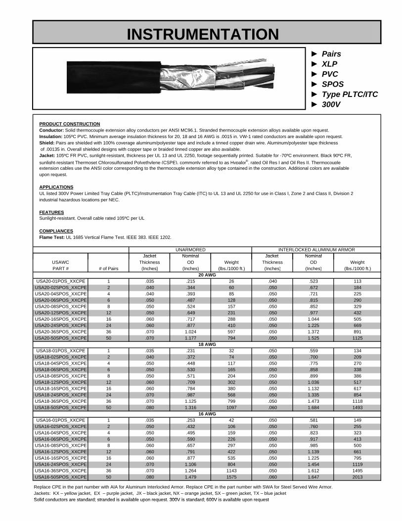
► Pairs► XLP► PVC► SPOS► Type PLTC/ITC► 300V
PRODUCT CONSTRUCTIONConductor: Solid thermocouple extension alloy conductors per ANSI MC96.1. Stranded thermocouple extension alloys available upon request.Insulation: 105ºC PVC. Minimum average insulation thickness for 20, 18 and 16 AWG is .0015 in. VW-1 rated conductors are available upon request.Shield: Pairs are shielded with 100% coverage aluminum/polyester tape and include a tinned copper drain wire. Aluminum/polyester tape thickness of .00135 in. Overall shielded designs with copper tape or braided tinned copper are also available.Jacket: 105ºC FR PVC, sunlight-resistant, thickness per UL 13 and UL 2250, footage sequentially printed. Suitable for -70ºC environment. Black 90ºC FR, sunlight-resistant Thermoset Chlorosulfonated Polyethylene (CSPE), commonly referred to as Hypalon®, rated Oil Res I and Oil Res II. Thermocouple extension cables use the ANSI color corresponding to the thermocouple extension alloy type contained in the construction. Additional colors are available upon request.
APPLICATIONSUL listed 300V Power Limited Tray Cable (PLTC)/Instrumentation Tray Cable (ITC) to UL 13 and UL 2250 for use in Class I, Zone 2 and Class II, Division 2industrial hazardous locations per NEC.
FEATURESSunlight-resistant. Overall cable rated 105ºC per UL.
COMPLIANCESFlame Test: UL 1685 Vertical Flame Test. IEEE 383. IEEE 1202.
Jacket Nominal Jacket NominalUNARMORED INTERLOCKED ALUMINUM ARMOR
INSTRUMENTATION
Jacket Nominal Jacket NominalUSAWC Thickness OD Weight Thickness OD WeightPART # # of Pairs (Inches} (Inches) (lbs./1000 ft.) (Inches) (Inches) (lbs./1000 ft.)
USA20-01POS_XXCPE 1 .035 .215 26 .040 .523 113USA20-02SPOS_XXCPE 2 .040 .344 60 .050 .672 184USA20-04SPOS_XXCPE 4 .040 .393 85 .050 .721 225USA20-06SPOS_XXCPE 6 .050 .487 128 .050 .815 290USA20-08SPOS_XXCPE 8 .050 .524 157 .050 .852 329USA20-12SPOS_XXCPE 12 .050 .649 231 .050 .977 432USA20-16SPOS_XXCPE 16 .060 .717 288 .050 1.044 505USA20-24SPOS_XXCPE 24 .060 .877 410 .050 1.225 669USA20-36SPOS_XXCPE 36 .070 1.024 597 .050 1.372 891USA20-50SPOS_XXCPE 50 .070 1.177 794 .050 1.525 1125
USA18-01POS_XXCPE 1 .035 .231 32 .050 .559 134USA18-02SPOS_XXCPE 2 .040 .372 74 .050 .700 209USA18-04SPOS_XXCPE 4 .050 .448 117 .050 .775 270USA18-06SPOS_XXCPE 6 .050 .530 165 .050 .858 338USA18-08SPOS_XXCPE 8 .050 .571 204 .050 .899 386USA18-12SPOS_XXCPE 12 .060 .709 302 .050 1.036 517USA18-16SPOS_XXCPE 16 .060 .784 380 .050 1.132 617USA18-24SPOS_XXCPE 24 .070 .987 568 .050 1.335 854USA18-36SPOS_XXCPE 36 .070 1.125 799 .050 1.473 1118USA18-50SPOS_XXCPE 50 .080 1.316 1097 .060 1.684 1493
USA16-01POS_XXCPE 1 .035 .253 42 .050 .581 149USA16-02SPOS_XXCPE 2 .050 .432 106 .050 .760 255USA16-04SPOS_XXCPE 4 .050 .495 159 .050 .823 323USA16-06SPOS_XXCPE 6 .050 .590 226 .050 .917 413USA16-08SPOS_XXCPE 8 .060 .657 297 .050 .985 500USA16-12SPOS_XXCPE 12 .060 .791 422 .050 1.139 661USA16-16SPOS_XXCPE 16 .060 .877 535 .050 1.225 795USA16-24SPOS_XXCPE 24 .070 1.106 804 .050 1.454 1119USA16-36SPOS_XXCPE 36 .070 1.264 1143 .050 1.612 1495USA16-50SPOS_XXCPE 50 .080 1.479 1575 .060 1.647 2013
Replace CPE in the part number with AIA for Aluminum Interlocked Armor. Replace CPE in the part number with SWA for Steel Served Wire Armor.Jackets: KX – yellow jacket, EX – purple jacket, JX – black jacket, NX – orange jacket, SX – green jacket, TX – blue jacketSolid conductors are standard; stranded is available upon request 300V is standard; 600V is available upon request
20 AWG
18 AWG
16 AWG
Solid conductors are standard; stranded is available upon request. 300V is standard; 600V is available upon request

► Type DLO► Type RHH-RHW-2► EPR/XL-CPE► 600V – 2kV
PRODUCT CONSTRUCTIONConductor: 14 AWG through 1111.1 kcmil Class I, fully annealed, flexible, stranded, tin-coated copper per AAR 589.Insulation: Flame-retardant, cross-linked Ethylene Propylene (EP) with separator tape over the conductor to facilitate stripping.Jacket: Black, flame-retardant, sunlight-, ozone- and oil resistant, lead-free Cross-linked Chlorinated Polyethylene (XL-CPE). Other jacketcolors available upon request.
APPLICATIONSFor use up to 2 kV as power cables in wind turbine generator applications per UL Subject 6140. Also for use in diesel electric locomotives,mining and earth-moving equipment, and general purpose use as flexible power leads in cable trays (sizes 1/0 AWG and larger).
FEATURESResists oil, heat, flame, gear lubricants, ozone and sunlight. Designed to withstand continuous flexing. 90ºC wet or dry temperature rating. Flexible tinned copper stranding.
COMPLIANCESIndustry: Type RHH/RHW-2 per UL 44, UL File #E90494. c(UL)US Type RW90 per CSA C.22.2-38, UL File #E90494. ICEA S-95-658/NEMAWC70. For CT Use on 1/0 AWG and larger in accordance with NEC®. Accepted for listing as flame resistant by MSHA. RoHS compliant.Flame Test: UL 2556 VW-1, IEEE 1202/CSA FT4 for sizes 1/0 AWG and larger.
Size Approx.USAWC Net Wt.*Part # (Inches) (mm) (Inches) (mm) (1) (2) (lbs./1000 ft.)
USA14-01DLO 14 19/0.0147 0.045 1.1 0.20 5.1 25 35 30USA12 01DLO 12 19/0 0185 0 045 1 1 0 22 5 6 30 40 39
(AWGor kcmil)
Nominal Insulation Thickness Current AmpsCond.Strand
Nominal O.D.
PORTABLE CORD
USA12-01DLO 12 19/0.0185 0.045 1.1 0.22 5.6 30 40 39USA10-01DLO 10 27/24 0.045 1.1 0.25 6.4 40 55 56USA8-01DLO 8 37/24 0.055 1.4 0.33 8.3 55 80 87USA6-01DLO 6 61/24 0.060 1.5 0.38 9.7 75 105 131USA4-01DLO 4 105/24 0.060 1.5 0.46 11.7 95 140 202USA2-01DLO 2 154/24 0.060 1.5 0.51 13.0 130 190 285USA1-01DLO 1 224/24 0.080 2.0 0.64 16.3 150 220 417
USA1/0-01DLO 1/0 280/24 0.080 2.0 0.70 17.8 170 260 494USA2/0-01DLO 2/0 329/24 0.080 2.0 0.73 18.5 195 300 587USA3/0-01DLO 3/0 456/24 0.080 2.0 0.80 20.3 225 350 718USA4/0-01DLO 4/0 551/24 0.080 2.0 0.84 21.3 260 405 845USA262-01DLO 262.6 650/24 0.090 2.3 0.94 23.9 296 467 1050USA313-01DLO 313.3 777/24 0.090 2.3 1.00 25.3 326 522 1185USA373-01DLO 373.7 925/24 0.090 2.3 1.06 26.9 362 591 1384USA444-01DLO 444.4 1110/24 0.090 2.3 1.11 28.2 400 652 1634USA535-01DLO 535.3 1332/24 0.090 2.3 1.20 30.5 445 728 1925USA646-01DLO 646.4 1609/24 0.090 2.3 1.29 32.8 493 815 2307USA777-01DLO 777.7 1924/24 0.090 2.3 1.38 35.1 546 904 2728USA929-01DLO 929.9 2318/24 0.090 2.3 1.56 39.6 602 1014 3570USA1111-01DLO 1111.1 2745/24 0.115 2.9 1.77 44.9 635 1115 4232
Dimensions and weights are nominal and are subject to industry tolerances(1) Ampacities based on 90°C conductor and 30°C ambient temperature, based on the National Electrical Code® for not more than threecurrent-carrying conductors in raceway, cable or earth.(2) Ampacities based on single-conductor in free air, 90°C conductor temperature and an ambient air temperature of 30°C, in accordancewith the National Electrical Code®.*Actual shipping weight may vary.

► Type W 2kV► Single Conductor► Type RHH/RHW 600V► EPDM
PRODUCT CONSTRUCTIONConductor: 8 AWG through 500 kcmil fully annealed, stranded, bare copper.Insulation: Premium-grade 90ºC EPDM.Cable Reinforcement: An open polyester braid reinforcement is applied between the insulation and jacket for mechanical strength.Jacket: 90ºC, black. Temperature range: -40ºC to +90ºC. Voltage rating: 600V –Type RHH/RHW; 2kV –Type W.
APPLICATIONSFor use in portable power systems and entertainment industry activities such as theater, television, films, night clubs, mobile communication vans,spotlights and sound systems. Also for use in similar applications that require permanent or temporary power. Can be used in the permanent wiring of 600V power supplies, hoists, cranes and other applications where flexible power leads must be installed in conduit or raceways.
FEATURESWater and sunlight resistant. Designed to withstand severe environmental conditions. Withstands exposure to oil, acids, alkalies, heat, flame,moisture and chemicals. Meets or exceeds flame test requirements of MSHA and UL.
COMPLIANCESIndustry: UL Type W, UL Type RHH or RHW, MSHA approved, RoHS compliant
Size Approx.USAWC Net Wt.*Part # (Inches) (mm) (Inches) (mm) (Inches) (mm) (1) (2) (lbs./1000 ft.)
Nominal Ins.Thickness
T pe W 2kV (UL) and T pe RHH/RHW 600V (UL)
Nominal Cond.O.D.No. of
Cond.
NominalO.D.
Current Amps(AWG or
kcmil)Cond.Strand
PORTABLE CORD
USA8-01W 8 1 133 0.167 4.24 0.070 1.78 0.485 12.32 55 80 150USA6-01W 6 1 259 0.210 5.33 0.070 1.78 0.565 14.35 75 105 214USA4-01W 4 1 259 0.245 6.22 0.070 1.78 0.605 15.37 95 140 277USA2-01W 2 1 259 0.334 8.48 0.070 1.78 0.680 17.27 130 190 387USA1-01W 1 1 259 0.375 9.53 0.090 2.29 0.765 19.43 150 220 485
USA1/0-01W 1/0† 1 259 0.385 9.78 0.090 2.29 0.810 20.57 170 260 563USA2/0-01W 2/0† 1 259 0.475 12.07 0.090 2.29 0.885 22.48 195 300 679USA3/0-01W 3/0† 1 259 0.480 12.19 0.090 2.29 0.930 23.62 225 350 809USA4/0-01W 4/0† 1 259 0.570 14.48 0.090 2.29 0.980 24.89 260 405 973USA250-01W 250† 1 627 0.615 15.62 0.105 2.67 1.045 26.54 290 455 1155USA35001W 350† 1 855 0.725 18.42 0.105 2.67 1.145 29.08 350 570 1492USA500-01W 500† 1 1235 0.880 22.35 0.105 2.67 1.310 33.27 430 700 2048
(1) Ampacities based on 90°C conductor and 30°C ambient temperature based on Table 310-16 in the National Electrical Code® for RHH/RHW with not more than three current-carrying conducgtors in raceway, cable or earth.(2) Ampacities based on 90°C conductor and 30°C ambient temperature based on Table 310-17 amd Table 400.5(B) in the National Electrical Code® forsingle-conductor cables.*Actual shipping weight may vary.†Designated for CT use.
Type W 2kV (UL) and Type RHH/RHW 600V (UL)
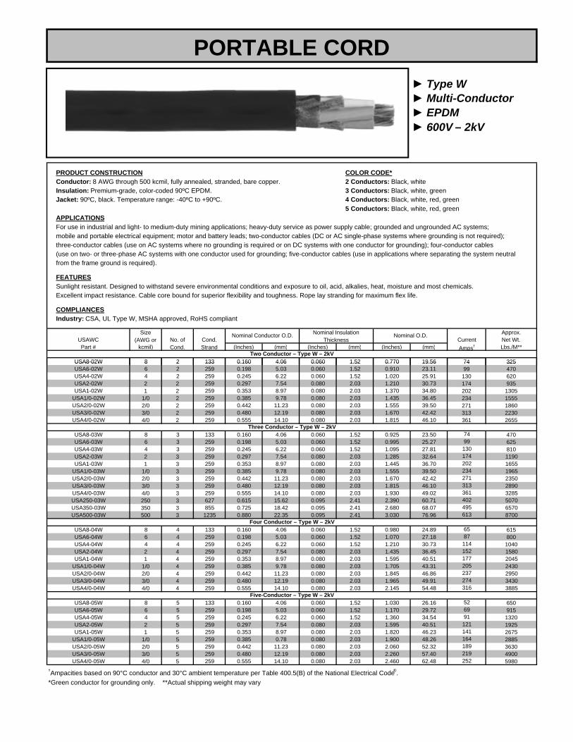
► Type W► Multi-Conductor► EPDM► 600V – 2kV
PRODUCT CONSTRUCTION COLOR CODE*Conductor: 8 AWG through 500 kcmil, fully annealed, stranded, bare copper. 2 Conductors: Black, whiteInsulation: Premium-grade, color-coded 90ºC EPDM. 3 Conductors: Black, white, greenJacket: 90ºC, black. Temperature range: -40ºC to +90ºC. 4 Conductors: Black, white, red, green
5 Conductors: Black, white, red, greenAPPLICATIONSFor use in industrial and light- to medium-duty mining applications; heavy-duty service as power supply cable; grounded and ungrounded AC systems;mobile and portable electrical equipment; motor and battery leads; two-conductor cables (DC or AC single-phase systems where grounding is not required);three-conductor cables (use on AC systems where no grounding is required or on DC systems with one conductor for grounding); four-conductor cables(use on two- or three-phase AC systems with one conductor used for grounding; five-conductor cables (use in applications where separating the system neutralfrom the frame ground is required).
FEATURESSunlight resistant. Designed to withstand severe environmental conditions and exposure to oil, acid, alkalies, heat, moisture and most chemicals.Excellent impact resistance. Cable core bound for superior flexibility and toughness. Rope lay stranding for maximum flex life.
COMPLIANCESIndustry: CSA, UL Type W, MSHA approved, RoHS compliant
Approx.USAWC Net Wt.Part # kcmil) (Inches) (mm) (Inches) (mm) (Inches) (mm) Lbs./M**
USA8-02W 8 2 133 0.160 4.06 0.060 1.52 0.770 19.56 32574
Cond.Strand
Nominal Insulation Thickness
Two Conductor – Type W – 2kV
Nominal Conductor O.D.CurrentAmps†
Size(AWG or No. of
Cond.
Nominal O.D.
PORTABLE CORD
USA8 02W 8 2 133 0.160 4.06 0.060 1.52 0.770 19.56 325USA6-02W 6 2 259 0.198 5.03 0.060 1.52 0.910 23.11 470USA4-02W 4 2 259 0.245 6.22 0.060 1.52 1.020 25.91 620USA2-02W 2 2 259 0.297 7.54 0.080 2.03 1.210 30.73 935USA1-02W 1 2 259 0.353 8.97 0.080 2.03 1.370 34.80 1305
USA1/0-02W 1/0 2 259 0.385 9.78 0.080 2.03 1.435 36.45 1555USA2/0-02W 2/0 2 259 0.442 11.23 0.080 2.03 1.555 39.50 1860USA3/0-02W 3/0 2 259 0.480 12.19 0.080 2.03 1.670 42.42 2230USA4/0-02W 4/0 2 259 0.555 14.10 0.080 2.03 1.815 46.10 2655
USA8-03W 8 3 133 0.160 4.06 0.060 1.52 0.925 23.50 470USA6-03W 6 3 259 0.198 5.03 0.060 1.52 0.995 25.27 625USA4-03W 4 3 259 0.245 6.22 0.060 1.52 1.095 27.81 810USA2-03W 2 3 259 0.297 7.54 0.080 2.03 1.285 32.64 1190USA1-03W 1 3 259 0.353 8.97 0.080 2.03 1.445 36.70 1655
USA1/0-03W 1/0 3 259 0.385 9.78 0.080 2.03 1.555 39.50 1965USA2/0-03W 2/0 3 259 0.442 11.23 0.080 2.03 1.670 42.42 2350USA3/0-03W 3/0 3 259 0.480 12.19 0.080 2.03 1.815 46.10 2890USA4/0-03W 4/0 3 259 0.555 14.10 0.080 2.03 1.930 49.02 3285USA250-03W 250 3 627 0.615 15.62 0.095 2.41 2.390 60.71 5070USA350-03W 350 3 855 0.725 18.42 0.095 2.41 2.680 68.07 6570USA500-03W 500 3 1235 0.880 22.35 0.095 2.41 3.030 76.96 8700
USA8-04W 8 4 133 0.160 4.06 0.060 1.52 0.980 24.89 615USA6-04W 6 4 259 0.198 5.03 0.060 1.52 1.070 27.18 800USA4-04W 4 4 259 0.245 6.22 0.060 1.52 1.210 30.73 1040USA2-04W 2 4 259 0.297 7.54 0.080 2.03 1.435 36.45 1580USA1-04W 1 4 259 0.353 8.97 0.080 2.03 1.595 40.51 2045
USA1/0-04W 1/0 4 259 0.385 9.78 0.080 2.03 1.705 43.31 2430USA2/0-04W 2/0 4 259 0.442 11.23 0.080 2.03 1.845 46.86 2950USA3/0-04W 3/0 4 259 0.480 12.19 0.080 2.03 1.965 49.91 3430USA4/0-04W 4/0 4 259 0.555 14.10 0.080 2.03 2.145 54.48 3885
USA8-05W 8 5 133 0.160 4.06 0.060 1.52 1.030 26.16 650USA6-05W 6 5 259 0.198 5.03 0.060 1.52 1.170 29.72 915USA4-05W 4 5 259 0.245 6.22 0.060 1.52 1.360 34.54 1320USA2-05W 2 5 259 0.297 7.54 0.080 2.03 1.595 40.51 1925USA1-05W 1 5 259 0.353 8.97 0.080 2.03 1.820 46.23 2675
USA1/0-05W 1/0 5 259 0.385 0.78 0.080 2.03 1.900 48.26 2885USA2/0-05W 2/0 5 259 0.442 11.23 0.080 2.03 2.060 52.32 3630USA3/0-05W 3/0 5 259 0.480 12.19 0.080 2.03 2.260 57.40 4900USA4/0-05W 4/0 5 259 0.555 14.10 0.080 2.03 2.460 62.48 5980
†Ampacities based on 90°C conductor and 30°C ambient temperature per Table 400.5(B) of the National Electrical Code®.*Green conductor for grounding only. **Actual shipping weight may vary
164189219252
Five-Conductor – Type W – 2kV526991
121141
7499
202
174202234
130
Three Conductor – Type W – 2kV
495613
234271313
402
7499
1148765
Four Conductor – Type W – 2kV
361
174
130
271313361
205237274316
177152

► Type G-GC► 3 and 4 Conductor► EPDM► 600V – 2kV
PRODUCT CONSTRUCTION COLOR CODE*Conductor: 8 AWG through 500 kcmil fully annealed, stranded, bare copper. 3 Conductors: Black, white, redInsulation: Premium-grade, color-coded 90ºC EPDM. Insulated grounds and 4 Conductors: Black, white, red, orangeground checks.Jacket: 90ºC, black. Temperature range: -40ºC to +90ºC.
APPLICATIONSFor use in industrial and light- to medium-duty mining applications; heavy-duty service as power supply cable; mobile and portable electrical equipment;three- and four-conductor cables (use on three-phase AC systems where grounding is required).
FEATURESSunlight resistant. Designed to withstand exposure to oil, acids, alkalies, heat, moisture and most chemicals. Excellent impact and abrasion resistance.Indent-printed for easy identification. Non-wicking rubber fillers. Rope lay stranding for maximum flex life. Cable core bound for superior flexibility and toughness.
COMPLIANCESIndustry: CSA, UL Type G, G-GC, MSHA approved, RoHS compliant.
Approx.USAWC Net Wt.*Part # kcmil) (Inches) (mm) (Inches) (mm) (Inches) (mm) (lbs./1000 ft.)
USA8-03GGC 8 3 133 0.160 4.06 10 2#10 0.060 1.52 0.965 24.51 600
YellowGroundCheck(AWG)
GreenGroundCheck(AWG)
Nominal O.D.
65
Cond.Strand
Nominal InsulationThickness
Three Conductor – Type G-GC – 2kV
Nominal Cond. O.D. CurrentAmps†
Size(AWG or No. of
Cond.
PORTABLE CORD
USA8-03GGC 8 3 133 0.160 4.06 10 2#10 0.060 1.52 0.965 24.51 600USA6-03GGC 6 3 259 0.198 5.03 10 2#10 0.060 1.52 1.020 25.91 770USA4-03GGC 4 3 259 0.245 6.22 10 2#8 0.060 1.52 1.125 28.58 1005USA2-03GGC 2 3 259 0.297 7.54 10 2#7 0.080 2.03 1.315 33.40 1480USA1-03GGC 1 3 259 0.353 8.97 8 2#6 0.080 2.03 1.445 36.70 1815
USA1/0-03GGC 1/0 3 259 0.385 9.78 8 2#5 0.080 2.03 1.570 39.88 2205USA2/0-03GGC 2/0 3 259 0.442 11.23 8 2#4 0.080 2.03 1.660 42.16 2545USA3/0-03GGC 3/0 3 259 0.480 12.19 8 2#3 0.080 2.03 1.810 45.97 3230USA4/0-03GGC 4/0 3 259 0.555 14.10 8 2#2 0.080 2.03 1.920 48.77 3675USA250-03GGC 250 3 627 0.615 15.62 8 2#2 0.095 2.41 2.390 60.71 6060USA350-03GGC 350 3 855 0.725 18.42 8 2#1/0 0.095 2.41 2.680 68.07 7400USA500-03GGC 500 3 1235 0.880 22.35 8 2#2/0 0.095 2.41 3.030 76.96 10100
Approx.USAWC Net Wt.*Part # kcmil) (inches) (mm) (Inches) (mm) (Inches) (mm) (lbs./1000 ft.)
USA8-04GGC 8 4 133 0.160 4.06 4#12 0.060 1.52 1.045 26.54 690USA6-04GGC 6 4 259 0.198 5.03 4#12 0.060 1.52 1.125 28.58 880USA4-04GGC 4 4 259 0.245 6.22 4#10 0.060 1.52 1.225 31.12 1160USA2-04GGC 2 4 259 0.297 7.54 4#9 0.080 2.03 1.435 36.45 1720USA1-04GGC 1 4 259 0.353 8.97 4#8 0.080 2.03 1.595 40.51 2200
USA1/0-04GGC 1/0 4 259 0.385 9.78 4#7 0.080 2.03 1.730 43.94 2705USA2/0-04GGC 2/0 4 259 0.442 11.23 4#6 0.080 2.03 1.855 47.12 3190USA3/0-04GGC 3/0 4 259 0.480 12.19 4#5 0.080 2.03 2.040 51.82 4005USA4/0-04GGC 4/0 4 259 0.555 14.10 4#4 0.080 2.03 2.145 54.48 4560
†Ampacities based on 90°C conductor and 30°C ambient temperature based on Table 400.5(B) of the National Electrical Code®.*Actual shipping may vary.
142164190219253
Four Conductor – Type G – 600V/2kV527091
122
Nominal O.D. CurrentAmps†No. of
Cond.Cond.Strand
GreenGroundCheck
AWG Size
Size(AWG or
Nominal Cond., O.D. Nominal Ins.Thickness
274237205177
352433536
316
1521148765

► Welding Cable► Class K► 30 AWG Stranding► 600V
PRODUCT CONSTRUCTIONConductor: 6 AWG through 500 kcmil fully annealed, stranded, bare copper, Class K.Jacket: Premium-grade 90ºC EPDM, black or red. Temperature range: -40ºC to +90ºC.
APPLICATIONSFor use with secondary voltage resistance welding leads and power supply applications not exceeding 600V AC.
FEATURESGood flexibility, abrasion resistance, good color retention.
COMPLIANCESIndustry: RoHS compliant
Approx.USAWC Net Wt.*Part # (Inches) (mm) (lbs./1000 ft.)
USA6-01WELD 6 259/30 0.380 9.65 135 250'USA4-01WELD 4 406/30 0.400 10.16 172 250'USA2-01WELD 2 646/30 0.465 11.81 260 250'USA1-01WELD 1 812/30 0.495 12.57 317 250'
USA1/0-01WELD 1/0 1025/30 0.560 14.22 400 250'USA2/0-01WELD 2/0 1274/30 0.615 15.62 487 250'USA3/0-01WELD 3/0 1613/30 0.670 17.02 605 250'USA4/0-01WELD 4/0 2029/30 0.750 19.05 827 250'
Size(AWG)
Nominal O.D.Standard Carton
Class K Welding Cable – 600V – 30 AWG Stranding
Cond.Strand
PORTABLE CORD
USA4/0 01WELD 4/0 2029/30 0.750 19.05 827 250USA250-01WELD 250 kcmil 2496/30 0.830 21.08 976 250'USA350-01WELD 350 kcmil 3441/30 0.960 24.38 1338 250'USA500-01WELD 500 kcmil 5054/30 1.200 30.48 1995 250'
*Actual shipping weight may vary.
Amps 100' 150' 200' 250' 300' 350' 400'100 4 4 2 2 1 1/0 1/0150 4 2 1 1/0 2/0 3/0 3/0200 2 1 1/0 2/0 3/0 4/0 4/0250 1 1/0 2/0 3/0 4/0300 1/0 2/0 3/0 4/0350 1/0 3/0 4/0400 2/0 3/0450 2/0 4/0500 3/0 4/0550 3/0 4/0600 4/0
(140°F), an ambient temperature of 40°C (104°F) and yield load factors from approximately 32% for the 2 AWG cable to approximately 23% for the 3/0 AWGcable, and higher for smaller sizes. The sizes of cables generally used range from 2 AWG to 3/0 AWG. In actual service, the load factor may be much higherthan indicated without overheating the cable, as the ambient temperature will generally be substantially lower than 40°C.
Suggested Ampacities for 600V Inline ApplicationsAWG or kcmil Amperes AWG Amperes
500 kcmil 695 1/0 190350 kcmil 552 1 160250 kcmil 445 2 140
4/0 310 4 1003/0 265 6 752/0 223
Ampacities for portable cable, continuous duty (ambient temperature of 40°C).May not be suitable for all installations per National Electrical Code ®.
Welding Cable Ampacities Single ConductorRequired Cable Sizes: For Welding Cable Application
Required cable sizes shown in AWG numbers.
Length is in feet for total circuit for secondary voltages only – do not use this table for 600V inline applications.
The total circuit length includes both welding and ground leads (based on 4-volt drop) 60% duty cycle. These values are based on a copper temperature of 60°C
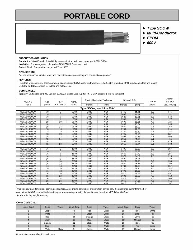
► Type SOOW► Multi-Conductor► EPDM► 600V
PRODUCT CONSTRUCTIONConductor: 18 AWG and 16 AWG fully annealed, stranded, bare copper per ASTM B-174.Insulation: Premium-grade, color-coded 90ºC EPDM. See color chart.Jacket: Black. Temperature range: -40ºC to +90ºC.
APPLICATIONSFor use with control circuits; tools; and heavy industrial, processing and construction equipment.
FEATURESResistant to oil, solvents, flame, abrasion, ozone, sunlight (UV), water and weather. Extra-flexible stranding. 90ºC-rated conductors and jacket.UL listed and CSA certified for indoor and outdoor use.
COMPLIANCESIndustry: UL flexible cord (UL Subject 62, CSA Flexible Cord (C22.2-49), MSHA approved, RoHS compliant
Approx.USAWC Net Wt.*Part # (Inches) (mm) (Inches) (mm) (lbs./1000 ft.)
USA18-05SOOW 18 5 16/30 0.030 0.76 0.465 11.81 5.6 141USA18-06SOOW 18 6 16/30 0.030 0.76 0.495 12.57 5.6 152USA18-07SOOW 18 7 16/30 0.030 0.76 0.520 13.21 5.6 172USA18-08SOOW 18 8 16/30 0.030 0.76 0.530 13.46 4.9 177USA18-10SOOW 18 10 16/30 0.030 0.76 0.595 15.11 4.9 225
Size(AWG)
CurrentAmps†
No. ofConductors
Nominal Insulation ThicknessCond.Strand
Type SOOW, Non-UL – 600V
Nominal O.D.
PORTABLE CORD
USA18 10SOOW 18 10 16/30 0.030 0.76 0.595 15.11 4.9 225USA18-12SOOW 18 12 16/30 0.030 0.76 0.600 15.24 3.5 240USA18-14SOOW 18 14 16/30 0.030 0.76 0.630 16.00 3.5 265USA18-16SOOW 18 16 16/30 0.030 0.76 0.700 17.78 3.5 310USA18-18SOOW 18 18 16/30 0.030 0.76 0.760 19.30 3.5 345USA18-20SOOW 18 20 16/30 0.030 0.76 0.795 20.19 3.5 382USA18-22SOOW 18 22 16/30 0.030 0.76 0.805 20.45 3.1 400USA18-24SOOW 18 24 16/30 0.030 0.76 0.850 21.59 3.1 451USA18-27SOOW 18 27 16/30 0.030 0.76 0.865 21.97 3.1 475USA18-30SOOW 18 30 16/30 0.030 0.76 0.915 23.24 3.1 533
USA16-05SOOW 16 5 26/30 0.030 0.76 0.495 12.57 8.0 167USA16-06SOOW 16 6 26/30 0.030 0.76 0.520 13.21 8.0 182USA16-07SOOW 16 7 26/30 0.030 0.76 0.540 13.72 8.0 194USA16-08SOOW 16 8 26/30 0.030 0.76 0.575 14.61 7.0 218USA16-09SOOW 16 9 26/30 0.030 0.76 0.600 15.24 7.0 243USA16-10SOOW 16 10 26/30 0.030 0.76 0.620 15.75 5.0 255USA16-12SOOW 16 12 26/30 0.030 0.76 0.660 16.76 5.0 296USA16-14SOOW 16 14 26/30 0.030 0.76 0.730 18.54 5.0 352USA16-16SOOW 16 16 26/30 0.030 0.76 0.740 18.80 5.0 383USA16-18SOOW 16 18 26/30 0.030 0.76 0.770 19.56 5.0 417USA16-20SOOW 16 20 26/30 0.030 0.76 0.810 20.57 5.0 457USA16-22SOOW 16 22 26/30 0.030 0.76 0.900 22.86 4.5 510USA16-24SOOW 16 24 26/30 0.030 0.76 0.925 23.50 4.5 563USA16-26SOOW 16 26 26/30 0.030 0.76 0.965 24.51 4.5 611USA16-30SOOW 16 30 26/30 0.030 0.76 1.010 25.65 4.5 767
†Values shown are for current-carrying conductors. A grounding conductor, or one which carries only the unbalance current from otherconductors, is NOT counted in determining current-carrying capacity. Ampacities are based on NEC Table 400.5(A)*Actual shipping weight may vary.
Color Code ChartNo. of Cond. Color Tracer No. of Cond. Color Tracer No. of Cond. Color Tracer
1 Black — 8 Red Black 15 Blue White2 White — 9 Green Black 16 Black Red3 Red — 10 Orange Black 17 White Red4 Green — 11 Blue Black 18 Orange Red5 Orange — 12 Black White 19 Blue Red6 Blue — 13 Red White 20 Red Green7 White Black 14 Green White 21 Orange Green
Note: Colors repeat after 21 conductors.

► Type SOOW► Multi-Conductor► EPDM► 600V
PRODUCT CONSTRUCTIONConductor: 14 through 10 AWG fully annealed, stranded, bare copper per ASTM B174.Insulation: Premium-grade, color-coded 90ºC EPDM. See color chart.Jacket: Black. Temperature range: -40ºC to +90ºC.
APPLICATIONSFor use with control circuits and tools plus heavy industrial, processing and construction equipment.
FEATURESResistant to oil, solvents, flame, abrasion, ozone, sunlight (UV), water and weather. Extra-flexible stranding. 90ºC-rated conductors and jacket.UL listed and CSA certified for indoor and outdoor use.
COMPLIANCESIndustry: UL flexible cord (UL Subject 62). CSA Flexible Cord (C22.2-49). MSHA approved. RoHS compliant.
Approx.USAWC Net Wt.
Part # (Inches) (mm) (Inches) (mm) (lbs./1000 ft.)*
USA14-O5SOOW 14 5 41/30 0.045 1.14 0.645 16.38 12.0 269USA14-O6SOOW 14 6 41/30 0.045 1.14 0.710 18.03 12.0 317USA14-O7SOOW 14 7 41/30 0.045 1.14 0.710 18.03 12.0 347USA14-O8SOOW 14 8 41/30 0.045 1.14 0.760 19.30 10.5 430USA14-O9SOOW 14 9 41/30 0.045 1.14 0.830 21.08 10.5 417USA14-10SOOW 14 10 41/30 0.045 1.14 0.820 20.83 10.5 427USA14-12SOOW 14 12 41/30 0 045 1 14 0 855 21 72 7 5 493
Size(AWG)
CurrentAmps†
No. ofConductors
Nominal Insulation ThicknessCond.Strand
Type SOOW – 600V – UL/CSA
Nominal O.D.
PORTABLE CORD
USA14-12SOOW 14 12 41/30 0.045 1.14 0.855 21.72 7.5 493USA14-14SOOW 14 14 41/30 0.045 1.14 1.000 25.40 7.5 601USA14-16SOOW 14 16 41/30 0.045 1.14 1.030 26.16 7.5 678USA14-18SOOW 14 18 41/30 0.045 1.14 1.100 27.94 7.5 720USA14-20SOOW 14 20 41/30 0.045 1.14 1.120 28.45 7.5 806USA14-24SOOW 14 24 41/30 0.045 1.14 1.260 32.00 6.7 1003USA14-28SOOW 14 28 41/30 0.045 1.14 1.330 33.78 6.7 1080USA14-30SOOW 14 30 41/30 0.045 1.14 1.335 33.91 6.0 1153
USA12-O5SOOW 12 5 65/30 0.045 1.14 0.715 18.16 16.0 333USA12-O6SOOW 12 6 65/30 0.045 1.14 0.740 18.80 16.0 412USA12-O7SOOW 12 7 65/30 0.045 1.14 0.790 20.07 16.0 465USA12-O8SOOW 12 8 65/30 0.045 1.14 0.825 20.96 14.0 526USA12-O9SOOW 12 9 65/30 0.045 1.14 0.900 22.86 14.0 517USA12-10SOOW 12 10 65/30 0.045 1.14 1.000 25.40 14.0 649USA12-12SOOW 12 12 65/30 0.045 1.14 1.010 25.65 10.0 669USA12-14SOOW 12 14 65/30 0.045 1.14 1.020 25.91 10.0 731USA12-16SOOW 12 16 65/30 0.045 1.14 1.135 28.83 10.0 933USA12-18SOOW 12 18 65/30 0.045 1.14 1.175 29.85 10.0 920USA12-20SOOW 12 20 65/30 0.045 1.14 1.170 29.72 10.0 989USA12-24SOOW 12 24 65/30 0.045 1.14 1.435 36.45 9.0 1273USA12-26SOOW 12 26 65/30 0.045 1.14 1.380 35.05 9.0 1324USA12-27SOOW 12 27 65/30 0.045 1.14 1.455 37.72 9.0 1325USA12-28SOOW 12 28 65/30 0.045 1.14 1.500 38.10 9.0 1355USA12-30SOOW 12 30 65/30 0.045 1.14 1.455 36.96 9.0 1492
USA10-05SOOW 10 5 104/30 0.045 1.14 0.770 19.56 20.0 472USA10-06SOOW 10 6 104/30 0.045 1.14 0.875 22.23 20.0 565USA10-07SOOW 10 7 104/30 0.045 1.14 0.900 22.86 20.0 552USA10-08SOOW 10 8 104/30 0.045 1.14 0.935 23.75 17.5 682USA10-10SOOW 10 10 104/30 0.045 1.14 1.020 25.91 17.5 758USA10-12SOOW 10 12 104/30 0.045 1.14 1.070 27.18 12.5 871USA10-16SOOW 10 16 104/30 0.045 1.14 1.230 31.24 12.5 1147USA10-20SOOW 10 20 104/30 0.045 1.14 1.325 33.66 12.5 1445
†Values shown are for current-carrying conductors. A grounding conductor, or one which carries only the unbalance current from otherconductors, is NOT counted in determining current-carrying capacity. Ampacities are based on NEC Table 400.5(A).*Actual shipping weight may vary.
Color Code ChartNo. of Cond. Color Tracer No. of Cond. Color Tracer No. of Cond. Color Tracer
1 Black — 8 Red Black 15 Blue White2 White — 9 Green Black 16 Black Red3 Red — 10 Orange Black 17 White Red4 Green — 11 Blue Black 18 Orange Red5 Orange — 12 Black White 19 Blue Red6 Blue 13 Red White 20 Red Green7 White Black 14 Green White 21 Orange Green
NOTE: Colors repeat after 21 conductors.

► Type SOOW► Multi-Conductor► EPDM► 600V
PRODUCT CONSTRUCTIONConductor: 8 AWG through 2 AWG fully annealed, stranded, bare copper per ASTM B174.Insulation: Premium-grade, color-coded 90ºC EPDM. See color chart.Jacket: Black. Temperature range: -40ºC to +90ºC.
APPLICATIONSFor use with portable tools and equipment, motors and associated machinery, and for temporary and portable power.
FEATURESOzone, sunlight (UV) and weather resistant. Excellent resistance to oil, moisture and abrasion. High flexibility. Good tensile strength, elongationand aging characteristics.
COMPLIANCESIndustry: MSHA approved, RoHS compliant
Approx.USAWC Net Wt.*Part # (Inches) (mm) (Inches) (mm) (lbs./1000 ft.)
USA8-02SOOW 8 2 65/26 0.050 1.27 0.660 16.76 40 250' 278USA8-03SOOW 8 3 65/26 0.050 1.27 0.695 17.65 40 250' 343
Type SOOW, Non-UL – 600V
Nominal O.D.Size
(AWG)CurrentAmps†
No. ofConductors
Nominal Insulation ThicknessStandardCarton
Cond.Strand
PORTABLE CORD
USA8-04SOOW 8 4 65/26 0.050 1.27 0.760 19.30 35 250' 442USA8-05SOOW 8 5 65/26 0.050 1.27 0.840 21.34 28 250' 542
USA6-03SOOW 6 3 101/26 0.050 1.27 0.790 20.07 55 250' 482USA6-04SOOW 6 4 101/26 0.050 1.27 0.865 21.97 45 250' 599USA6-05SOOW 6 5 101/26 0.050 1.27 0.945 24.00 36 250' 750
USA4-02SOOW 4 2 119/25 0.050 1.27 0.860 21.84 70 250' 515USA4-03SOOW 4 3 119/25 0.050 1.27 0.915 23.24 70 250' 683USA4-04SOOW 4 4 119/25 0.050 1.27 1.000 25.40 60 250' 851USA4-05SOOW 4 5 119/25 0.050 1.27 1.095 27.81 48 250' 1039
USA2-03SOOW 2 3 133/.0211 0.055 1.40 1.085 27.56 95 250' 1003USA2-04SOOW 2 4 133/.0211 0.055 1.40 1.170 29.72 80 250' 1248USA2-05SOOW 2 5 133/.0211 0.055 1.40 1.390 35.31 64 250' 1684
†Green conductor for grounding only. Ampacities based on NEC Table 400.5(A)*Actual shipping weight may vary.
No. Cond.2 Black, white34 Black, white, red, green5
Black, white, green
Black, white, red, orange, green
Color

► Lighting Cable► UL Type SC► CSA Type PPC► 600V
PRODUCT CONSTRUCTIONConductor: 8 AWG through 4/0 AWG fully annealed, stranded, bare copper per ASTM B172.Jacket: 105ºC, black. Temperature range: -50ºC to +105ºC.
APPLICATIONSFor use in portable power systems and entertainment industry activities such as theater, television, films, night clubs, mobile communication vans,spotlights and sound systems. Also for use in similar applications that require temporary power.
FEATURESResistant to water and sunlight. Designed to withstand severe environmental conditions. Withstands exposure to oil, acids, alkalies, heat, flame,moisture and chemicals. Meets or exceeds flame test requirements of MSHA, CSA and UL. Indent printed.
COMPLIANCESIndustry: UL listed, CSA certified, RoHS compliant
Approx.USAWC Net Wt.*Part # (Inches) (mm) (lbs./1000 ft.)
USA8-01SC 8 168/30 0.385 9.78 80 110USA6-01SC 6 259/30 0.420 10.67 105 152USA4-01SC 4 416/30 0.475 12.07 140 215USA2 01SC 2 655/30 0 520 13 21 190 296
Size(AWG)
CurrentAmps†
NominalStrand
Nominal O.D.
PORTABLE CORD
USA2-01SC 2 655/30 0.520 13.21 190 296USA1-01SC 1 827/30 0.575 14.61 220 360
USA1/0-01SC 1/0† 1042/30 0.600 15.24 260 424USA2/0-01SC 2/0† 1316/30 0.645 16.38 300 513USA3/0-01SC 3/0† 1660/30 0.715 18.16 350 644USA4/0-01SC 4/0† 2062/30 0.765 19.43 405 824
†NEC Table 400-5(A)(2)*Actual shipping weight may vary.
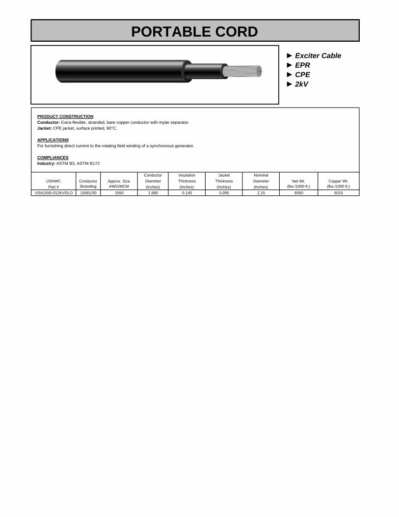
► Exciter Cable► EPR► CPE► 2kV
PRODUCT CONSTRUCTIONConductor: Extra-flexible, stranded, bare copper conductor with mylar separator.Jacket: CPE jacket, surface printed, 90°C.
APPLICATIONSFor furnishing direct current to the rotating field winding of a synchronous generator.
COMPLIANCESIndustry: ASTM B3, ASTM B172
Conductor Insulation Jacket NominalUSAWC Diameter Thickness Thickness DiameterPart # (Inches) (Inches) (Inches) (Inches)
USA1550-012KVDLO 15561/30 1550 1.680 0.140 0.095 2.15 6050 5015
ConductorStranding
Net Wt.(lbs./1000 ft.)
Approx. SizeAWG/MCM
Copper Wt.(lbs./1000 ft.)
PORTABLE CORD

► 1 Conductor► EPR► PVC► Type MV-105► 5kV and 8kV
PRODUCT CONSTRUCTIONConductor: 4 AWG through 1000 kcmil annealed bare copper compact Class B strand.Extruded Strand Shield (ESS): Extruded thermoset semi-conducting stress-control layer over conductor.Insulation: Ethylene Propylene Rubber (EPR) insulation, colored to contrast with the black conducting shield layers.Extruded Insulation Shield (EIS): Thermoset semi-conducting polymeric layer free stripping from insulation.Metallic Shield: 5 mil annealed copper tape with an overlap of 25%.Jacket: Lead-free, flame-retardant moisture- and sunlight-resistant Polyvinyl Chloride (PVC). Also available: (CPE) jacket.
APPLICATIONSFor use in aerial, conduit, open tray and underground duct installations. For use in wet or dry locations when installed in accordance with the NEC. Can be used in direct burial if installed in a system with a ground conductor that is in close proximity and conforms with NEC 250.4(A)(5). Superior performance in petrochemical plants, pulp and paper mills, sewage and water treatment plants, environmental protection systems, railroads, mines, utility power generating stations, steel mills, textile plants and other industrial three-phase applications.
FEATURESRated at 105ºC. Excellent heat, flame and moisture resistance. Outstanding corona resistance. High dielectric strength. Low moisture absorption.Electrically stable under stress. Low dielectric loss. Chemical-resistant. Meets cold bend test at -35ºC. loss.
COMPLIANCESIndustry: National Electrical Code (NEC). UL 1072. ICEA S-93-639/NEMA WC74. ICEA S-97-682. AEIC CS8. UL listed as type MV-105 for usein accordance with the NEC. Sizes 1/0 AWG and larger are listed and marked "Sunlight-Resistant FOR CT USE" in accordance with NEC.Flame Test: UL 1685 (Sizes 1/0 AWG and larger) UL Flame Exposure Test. IEEE 1202 (70,000 BTU/hr)/CSA FT4.Optional Flame Test: ICEA T-29-520 (210,000 BTU/hr). Other: EPA 40 CFR, Part 261, for leachable lead content per TCLP. OSHA acceptable.
NominalCopper
USAWC WeightPart # kcmil Insulation Jacket (Inches) (lbs./1000 ft.) (lbs./1000 ft.) Tray Conduit Duct
USA4-015KVESP 4 7 115 60 .50 350 178 - 110 120USA2-015KVESP 2 7 115 60 .56 460 259 - 145 155USA1-015KVESP 1 19 115 60 .60 565 315 - 175 180
USA1/0-015KVESP 1/0 19 115 60 .64 620 386 290 200 210USA2/0-015KVESP 2/0 19 115 80 .68 755 474 330 225 235USA3/0-015KVESP 3/0 19 115 80 .73 890 585 385 270 270USA4/0-015KVESP 4/0 19 115 80 .79 1055 725 445 305 310USA250-015KVESP 250 37 115 80 .85 1205 849 495 355 345USA350-015KVESP 350 37 115 80 .95 1570 1165 615 430 415USA500-015KVESP 500 37 115 80 1.08 2115 1639 775 530 505USA750-015KVESP 750 61 115 80 1.27 2995 2427 1000 665 630USA1000-015KVESP 1000 61 115 80 1.42 3870 3210 1200 770 720
*TRAY: Single layer in uncovered cable tray with one cable diameter spacing, 105̊C Conductor Temperature, 40˚C Ambient. CONDUIT: Three cables in isolated conduit
Copper Conductor
DiameterOver Ins.
1.34
.81
.84
1.20
5000 Volts – 133% Insulation Level or 8000 Volts – 100% Insulation Level
NominalDiameter
Approx.Net Wt.
Ampacity*
(Inches)
AWGor
Thickness in MilsNo. of
Strands
.71
.77
.93
.991.041.09
in air, 105˚C Conductor Temperature, 40˚C Ambient. DUCT: Three cables per duct, 105˚C Conductor Temperature, 20˚C Ambient, One Circuit, 100% Load Factor, Rho = 90. For other installation conditions refer to the NEC.
1.531.68
MEDIUM VOLTAGE POWER
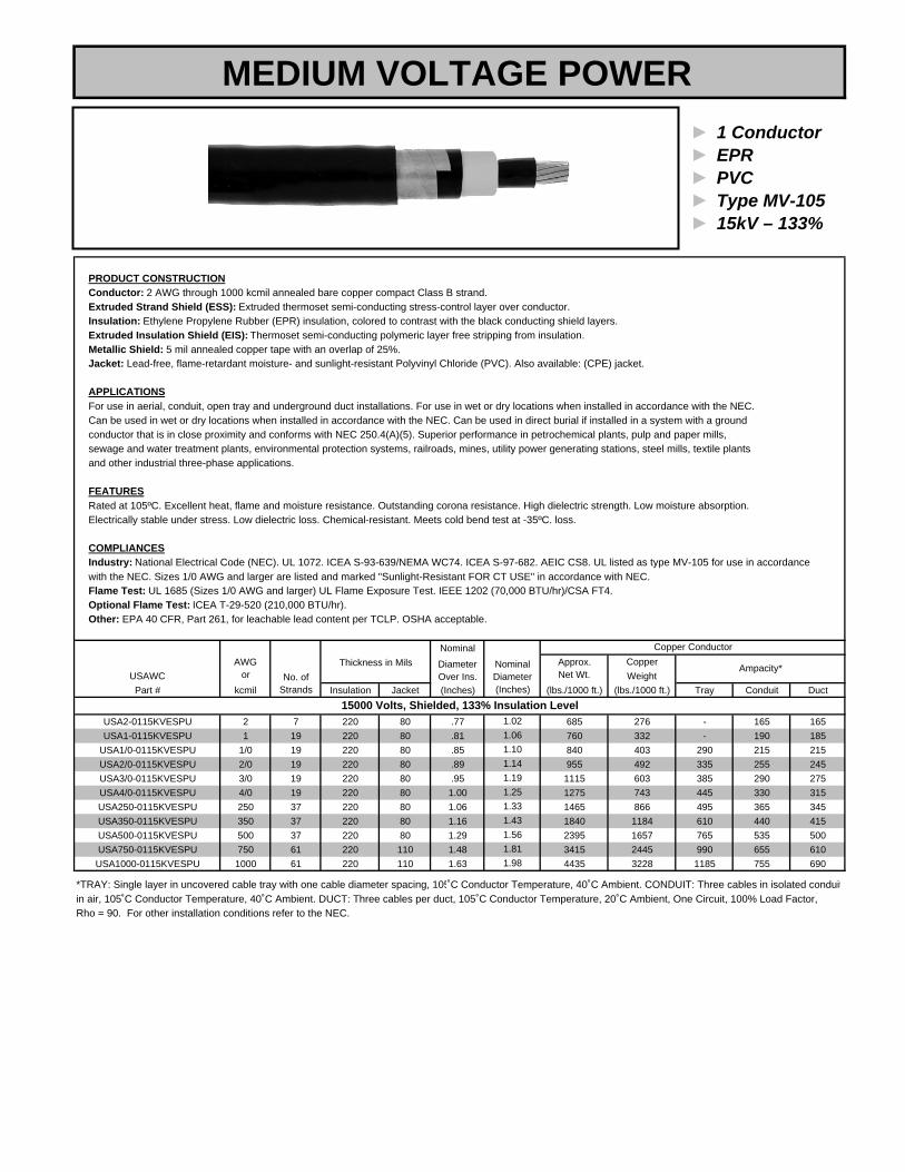
► 1 Conductor► EPR► PVC► Type MV-105► 15kV – 133%
PRODUCT CONSTRUCTIONConductor: 2 AWG through 1000 kcmil annealed bare copper compact Class B strand.Extruded Strand Shield (ESS): Extruded thermoset semi-conducting stress-control layer over conductor.Insulation: Ethylene Propylene Rubber (EPR) insulation, colored to contrast with the black conducting shield layers.Extruded Insulation Shield (EIS): Thermoset semi-conducting polymeric layer free stripping from insulation.Metallic Shield: 5 mil annealed copper tape with an overlap of 25%.Jacket: Lead-free, flame-retardant moisture- and sunlight-resistant Polyvinyl Chloride (PVC). Also available: (CPE) jacket.
APPLICATIONSFor use in aerial, conduit, open tray and underground duct installations. For use in wet or dry locations when installed in accordance with the NEC. Can be used in wet or dry locations when installed in accordance with the NEC. Can be used in direct burial if installed in a system with a ground conductor that is in close proximity and conforms with NEC 250.4(A)(5). Superior performance in petrochemical plants, pulp and paper mills, sewage and water treatment plants, environmental protection systems, railroads, mines, utility power generating stations, steel mills, textile plantsand other industrial three-phase applications.
FEATURESRated at 105ºC. Excellent heat, flame and moisture resistance. Outstanding corona resistance. High dielectric strength. Low moisture absorption.Electrically stable under stress. Low dielectric loss. Chemical-resistant. Meets cold bend test at -35ºC. loss.
COMPLIANCESIndustry: National Electrical Code (NEC). UL 1072. ICEA S-93-639/NEMA WC74. ICEA S-97-682. AEIC CS8. UL listed as type MV-105 for use in accordance with the NEC. Sizes 1/0 AWG and larger are listed and marked "Sunlight-Resistant FOR CT USE" in accordance with NEC.Flame Test: UL 1685 (Sizes 1/0 AWG and larger) UL Flame Exposure Test. IEEE 1202 (70,000 BTU/hr)/CSA FT4.Optional Flame Test: ICEA T-29-520 (210,000 BTU/hr). Other: EPA 40 CFR, Part 261, for leachable lead content per TCLP. OSHA acceptable.
NominalCopper
USAWC WeightPart # kcmil Insulation Jacket (Inches) (lbs./1000 ft.) (lbs./1000 ft.) Tray Conduit Duct
USA2-0115KVESPU 2 7 220 80 .77 685 276 - 165 165USA1-0115KVESPU 1 19 220 80 .81 760 332 - 190 185
USA1/0-0115KVESPU 1/0 19 220 80 .85 840 403 290 215 215USA2/0-0115KVESPU 2/0 19 220 80 .89 955 492 335 255 245USA3/0-0115KVESPU 3/0 19 220 80 .95 1115 603 385 290 275USA4/0-0115KVESPU 4/0 19 220 80 1.00 1275 743 445 330 315USA250-0115KVESPU 250 37 220 80 1.06 1465 866 495 365 345USA350-0115KVESPU 350 37 220 80 1.16 1840 1184 610 440 415USA500-0115KVESPU 500 37 220 80 1.29 2395 1657 765 535 500USA750-0115KVESPU 750 61 220 110 1.48 3415 2445 990 655 610
USA1000-0115KVESPU 1000 61 220 110 1.63 4435 3228 1185 755 690
*TRAY: Single layer in uncovered cable tray with one cable diameter spacing, 105̊C Conductor Temperature, 40˚C Ambient. CONDUIT: Three cables in isolated conduit
Copper Conductor
DiameterOver Ins.
1.81
1.101.14
1.56
15000 Volts, Shielded, 133% Insulation Level
NominalDiameter
Approx.Net Wt.
Ampacity*
(Inches)
AWGor
Thickness in MilsNo. of
Strands
1.021.06
1.191.251.331.43
in air, 105˚C Conductor Temperature, 40˚C Ambient. DUCT: Three cables per duct, 105˚C Conductor Temperature, 20˚C Ambient, One Circuit, 100% Load Factor, Rho = 90. For other installation conditions refer to the NEC.
1.98
MEDIUM VOLTAGE POWER

► 1 Conductor► EPR► PVC► Type MV-105► 35kV – 100%
PRODUCT CONSTRUCTIONConductor: 1/0 AWG through 1000 kcmil annealed bare copper compact Class B strand.Extruded Strand Shield (ESS): Extruded thermoset semi-conducting stress-control layer over conductor.Insulation: Ethylene Propylene Rubber (EPR) insulation, colored to contrast with the black conducting shield layers.Extruded Insulation Shield (EIS): Thermoset semi-conducting polymeric layer free stripping from insulation.Metallic Shield: 5 mil annealed copper tape with an overlap of 25%.Jacket: Lead-free, flame-retardant moisture- and sunlight-resistant Polyvinyl Chloride (PVC). Also available: (CPE) jacket.
APPLICATIONSFor use in aerial, conduit, open tray and underground duct installations. For use in wet or dry locations when installed in accordance with the NEC. Can be used in wet or dry locations when installed in accordance with the NEC. Can be used in direct burial if installed in a system with a ground conductor that is in close proximity and conforms with NEC 250.4(A)(5). Superior performance in petrochemical plants, pulp and paper mills, sewage and water treatment plants, environmental protection systems, railroads, mines, utility power generating stations, steel mills, textile plantsand other industrial three-phase applications.
FEATURESRated at 105ºC. Excellent heat, flame and moisture resistance. Outstanding corona resistance. High dielectric strength. Low moisture absorption.Electrically stable under stress. Low dielectric loss. Chemical-resistant. Meets cold bend test at -35ºC. loss.
COMPLIANCESIndustry: National Electrical Code (NEC). UL 1072. ICEA S-93-639/NEMA WC74. ICEA S-97-682. AEIC CS8. UL listed as type MV-105 for use in accordance with the NEC. Sizes 1/0 AWG and larger are listed and marked "Sunlight-Resistant FOR CT USE" in accordance with NEC.Flame Test: UL 1685 (Sizes 1/0 AWG and larger) UL Flame Exposure Test. IEEE 1202 (70,000 BTU/hr)/CSA FT4.Optional Flame Test: ICEA T-29-520 (210,000 BTU/hr). Other: EPA 40 CFR, Part 261, for leachable lead content per TCLP. OSHA acceptable.
NominalCopper
USAWC WeightPart # kcmil Insulation Jacket (Inches) (lbs./1000 ft.) (lbs./1000 ft.) Tray Conduit Duct
USA1/0-0135KVESPG 1/0 19 345 80 1.11 1160 425 290 215 215USA2/0-0135KVESPG 2/0 19 345 80 1.15 1290 514 330 255 245USA3/0-0135KVESPG 3/0 19 345 80 1.20 1445 625 380 290 275USA4/0-0135KVESPG 4/0 19 345 80 1.26 1635 765 445 330 315USA250-0135KVESPG 250 37 345 80 1.34 1805 888 490 365 345USA350-0135KVESPG 350 37 345 80 1.43 2205 1206 605 440 415USA500-0135KVESPG 500 37 345 80 1.56 2920 1679 755 535 500USA750-0135KVESPG 750 61 345 110 1.75 3895 2467 970 655 610
USA1000-0135KVESPG 1000 61 345 110 1.90 4840 3250 1160 755 690
*TRAY: Single layer in uncovered cable tray with one cable diameter spacing, 105̊C Conductor Temperature, 40˚C Ambient. CONDUIT: Three cables in isolated conduit
1.96
in air, 105˚C Conductor Temperature, 40˚C Ambient. DUCT: Three cables per duct, 105˚C Conductor Temperature, 20˚C Ambient, One Circuit, 100% Load Factor, Rho = 90. For other installation conditions refer to the NEC.
1.35
1.511.601.72
35000 Volts, Shielded, 100% Insulation Level
NominalDiameter
Approx.Net Wt.
Ampacity*
(Inches)
AWGor
Thickness in MilsNo. of
Strands
Copper Conductor
DiameterOver Ins.
1.401.45
2.10
1.31
MEDIUM VOLTAGE POWER

► 3 Conductors► EPR► PVC► Type MV-105► 5kV and 8kV
PRODUCT CONSTRUCTIONConductor: 4 AWG through 1000 kcmil annealed bare copper compact Class B strand.Extruded Strand Shield (ESS): Extruded thermoset semi-conducting stress-control layer over conductor.Insulation: Ethylene Propylene Rubber (EPR) insulation, colored to contrast with the black conducting shield layers.Extruded Insulation Shield (EIS): Thermoset semi-conducting polymeric layer free stripping from insulation.Metallic Shield: 5 mil annealed copper tape with an overlap of 25%.Jacket: Lead-free, flame-retardant moisture- and sunlight-resistant Polyvinyl Chloride (PVC). Also available: (CPE) jacket.
APPLICATIONSFor use in aerial, conduit, open tray, direct burial and underground duct installations. For use in wet or dry locations when installed in accordance with the NEC. Suitable for commercial, industrial and utility applications where space is limited, ease of installation is critical and reliability is the major concern.
FEATURESRated at 105ºC. Excellent heat, flame and moisture resistance. Outstanding corona resistance. High dielectric strength. Low moisture absorption. Electrically stable under stress. Low dielectric loss. Chemical-resistant. Meets cold bend test at -35ºC.
COMPLIANCESIndustry: National Electrical Code (NEC). UL 1072. ICEA S-93-639/NEMA WC74. ICEA S-97-682. AEIC CS8. UL listed as type MV-105 for use in accordance with the NEC. Sizes 1/0 AWG and larger are listed and marked "Sunlight-Resistant FOR CT USE" in accordance with NEC.Flame Test: UL 1685 (70,000 BTU/hr)Optional Flame Test: IEEE 1202 (70,000 BTU/hr)/CSA FT4. ICEA T-29-520 (210,000 BTU/hr.)Other: EPA 40 CFR, Part 261, for leachable lead content per TCLP. OSHA acceptable.
Size Nominal(AWG Diameter Copper
USAWC or No. of Over Ins. WeightPart # kcmil) Strands Insulation Jacket (Inches) (lbs./1000 ft.)
USA4-035KVESP 4 7 115 80 .50 616 115USA2-035KVESP 2 7 115 80 .56 860 154USA1-035KVESP 1 19 115 80 .60 1074 180
USA1/0-035KVESP 1/0 19 115 110 .64 1290 205USA2/0-035KVESP 2/0 19 115 110 .68 1556 240USA3/0-035KVESP 3/0 19 115 110 .73 1918 280USA4/0-035KVESP 4/0 19 115 110 .79 2344 320USA250-035KVESP 250 37 115 110 .85 2759 355USA350-035KVESP 350 37 115 110 .95 3713 440USA500-035KVESP 500 37 115 110 1.08 5191 545USA750-035KVESP 750 61 115 140 1.27 7629 685
USA1000-035KVESP 1000 61 115 140 1.42 10070 790
*TRAY: Single layer in uncovered cable tray with one cable diameter spacing, 105̊C Conductor Temperature, 40˚C Ambient. CONDUIT: Three cables in isolated conduitin air, 105˚C Conductor Temperature, 40˚C Ambient. DUCT: Three cables per duct, 105˚C Conductor Temperature, 20˚C Ambient, One Circuit, 100% Load Factor,
475
Conduit DuctSize
(AWG)Net Wt.
(lbs./1000 ft.)
660
2.252.13
1.70
585
2.47 2 5340 3902.79 1
2853 4160 3153 3685
2451.89 4 2585 210
1854 1950 155
Approx.
4 2250
Nom. Conductor
1575 1351.44 6 1245
Diam.(Inches)
Rho = 90. For other installation conditions refer to the NEC.
Ampacity*Grounding
1005000 Volts – 133% Insulation Level or 8000 Volts – 100% Insulation Level
1.57 6
Thickness in Mils
1.80
1299010275
2.00 3 3040
6610
3.59 1/03.26 1/0
MEDIUM VOLTAGE POWER

► 3 Conductors► EPR► PVC► Type MV-105► 15kV – 133%
PRODUCT CONSTRUCTIONConductor: 2 AWG through 1000 kcmil annealed bare copper compact Class B strand.Extruded Strand Shield (ESS): Extruded thermoset semi-conducting stress-control layer over conductor.Insulation: Ethylene Propylene Rubber (EPR) insulation, colored to contrast with the black conducting shield layers.Extruded Insulation Shield (EIS): Thermoset semi-conducting polymeric layer free stripping from insulation.Metallic Shield: 5 mil annealed copper tape with an overlap of 25%.Jacket: Lead-free, flame-retardant moisture- and sunlight-resistant Polyvinyl Chloride (PVC). Also available: (CPE) jacket.
APPLICATIONSFor use in aerial, conduit, open tray, direct burial and underground duct installations. For use in wet or dry locations when installed in accordance with the NEC. Suitable for commercial, industrial and utility applications where space is limited, ease of installation is critical and reliability is the major concern.
FEATURESRated at 105ºC. Excellent heat, flame and moisture resistance. Outstanding corona resistance. High dielectric strength. Low moisture absorption. Electrically stable under stress. Low dielectric loss. Chemical-resistant. Meets cold bend test at -35ºC.
COMPLIANCESIndustry: National Electrical Code (NEC). UL 1072. ICEA S-93-639/NEMA WC74. ICEA S-97-682. AEIC CS8. UL listed as type MV-105 for use in accordance with the NEC. Sizes 1/0 AWG and larger are listed and marked "Sunlight-Resistant FOR CT USE" in accordance with NEC.Flame Test: UL 1685 (70,000 BTU/hr)Optional Flame Test: IEEE 1202 (70,000 BTU/hr)/CSA FT4. ICEA T-29-520 (210,000 BTU/hr.)Other: EPA 40 CFR, Part 261, for leachable lead content per TCLP. OSHA acceptable.
Size Nominal(AWG Diameter Copper
USAWC or No. of Over Ins. WeightPart # kcmil) Strands Insulation Jacket (Inches) (lbs./1000 ft.)
USA2-0315KVESPU 2 7 220 110 .77 913 185USA1-0315KVESPU 1 19 220 110 .81 1125 210
USA1/0-0315KVESPU 1/0 19 220 110 .85 1343 240USA2/0-0315KVESPU 2/0 19 220 110 .90 1609 275USA3/0-0315KVESPU 3/0 19 220 110 .95 1972 315USA4/0-0315KVESPU 4/0 19 220 110 1.00 2398 360USA250-0315KVESPU 250 37 220 110 1.06 2812 400USA350-0315KVESPU 350 37 220 110 1.16 3766 490USA500-0315KVESPU 500 37 220 140 1.29 5244 600USA750-0315KVESPU 750 61 220 140 1.48 7682 745
USA1000-0315KVESPU 1000 61 220 140 1.61 10124 860
*CONDUIT: Three-conductor cable in isolated conduit in air, 105̊ C Conductor Temperature, 40˚C Ambient. AIR: Three-conductor cable isolated in air, 105˚CConductor Temperature, 40˚C Ambient. For other installation conditions refer to the NEC.
1398311510
2.52 3 3800
8340
3.99 2/03.73 1/0
Nom. Conductor
2410 1656
Diam.(Inches)
Ampacity*Grounding
Approx.
4 2965
15000 Volts – 133% Insulation Level2.09
Thickness in Mils
2.26 2154 2690 185
2802.36 4 3330 245
3202 5025 3503 4375
6465 4303.32 1
DuctSize
(AWG)Net Wt.
(lbs./1000 ft.)
525
Conduit
2.752.59
2.22
635
3.04 2
725
MEDIUM VOLTAGE POWER
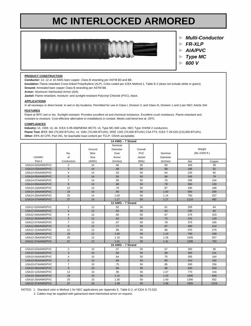
► Multi-Conductor► FR-XLP► AIA/PVC► Type MC► 600 V
PRODUCT CONSTRUCTIONConductor: 14, 12 or 10 AWG bare copper. Class B stranding per ASTM B3 and B8.Insulation: Flame-retardant Cross-linked Polyethylene (XLP). Color-coded per ICEA Method 1, Table E-2 (does not include white or green).Ground: Annealed bare copper Class B stranding per ASTM B8.Armor: Aluminum Interlocked Armor (AIA)Jacket: Flame-retardant, moisture- and sunlight-resistant Polyvinyl Chloride (PVC), black.
APPLICATIONSIn all raceways or direct burial. In wet or dry locations. Permitted for use in Class I, Division 2; and Class III, Division 1 and 2 per NEC Article 334.
FEATURESRated at 90ºC wet or dry. Sunlight-resistant. Provides excellent oil and chemical resistance. Excellent crush resistance. Flame-retardant andresistant to moisture. Cost-effective alternative to installations in conduit. Meets cold bend test at -25ºC.
COMPLIANCESIndustry: UL 1569. UL 44. ICEA S-95-658/NEMA WC70. UL Type MC-600 volts. NEC Type XHHW-2 conductors.Flame Test: IEEE 383 (70,000 BTU/hr). UL 1581 (70,000 BTU/hr). IEEE 1202 (70,000 BTU/hr) CSA FT4. ICEA T-29-520 (210,000 BTU/hr).Other: EPA 40 CFR, Part 261, for leachable lead content per TCLP. OSHA acceptable.
NominalGround Diameter Overall
No. Wire Over PVC NominalUSAWC of Size Armor Jacket DiameterPart # Conductors (AWG) (Inches) (Mils) (Inches) Net Copper
USA14-02AIAWGPVC 2 14 .46 50 .56 160 39USA14-03AIAWGPVC 3 14 .48 50 .58 185 52USA14-04AIAWGPVC 4 14 .53 50 .64 220 65USA14-05AIAWGPVC 5 14 .55 50 .66 245 79USA14-07AIAWGPVC 7 14 .59 50 .70 295 104USA14-09AIAWGPVC 9 14 .68 50 .78 360 130USA14-12AIAWGPVC 12 14 .76 50 .87 430 168USA14-19AIAWGPVC 19 14 .90 50 1.00 590 259USA14-25AIAWGPVC 25 14 1.03 50 1.14 750 337USA14-37AIAWGPVC 37 14 1.17 50 1.27 1110 492
USA12-02AIAWGPVC 2 12 .52 50 .61 205 64USA12-03AIAWGPVC 3 12 .53 50 .63 230 83USA12-04AIAWGPVC 4 12 .56 50 .67 275 103USA12-05AIAWGPVC 5 12 .63 50 .73 315 129USA12-07AIAWGPVC 7 12 .67 50 .78 375 165USA12-09AIAWGPVC 9 12 .77 50 .87 460 214USA12-12AIAWGPVC 12 12 .85 50 .96 570 279USA12-19AIAWGPVC 19 12 1.00 50 1.10 790 428USA12-25AIAWGPVC 25 12 1.15 50 1.26 1035 557USA12-37AIAWGPVC 37 12 1.31 50 1.41 1395 793
USA10-02AIAWGPVC 2 10 .57 50 .67 260 96USA10-03AIAWGPVC 3 10 .58 50 .68 300 131USA10-04AIAWGPVC 4 10 .64 50 .75 355 164USA10-05AIAWGPVC 5 10 .69 50 .80 410 192USA10-07AIAWGPVC 7 10 .75 50 .85 500 256USA10-09AIAWGPVC 9 10 .86 50 .96 620 320USA10-12AIAWGPVC 12 10 .96 50 1.07 770 416USA10-19AIAWGPVC 19 10 1.12 50 1.22 1095 640USA10-25AIAWGPVC 25 10 1.30 50 1.40 1390 832USA10-37AIAWGPVC 37 10 1.48 50 1.58 1935 1216
10 AWG – 7 Strand
NOTES: 1. Standard color is Method 1 for NEC applications per Appendix E, Table E-2, of ICEA S-73-532.
12 AWG – 7 Strand
2. Cables may be supplied with galvanized steel interlocked armor on request.
14 AWG – 7 Strand
(lbs./1000 ft.)Weight
MC INTERLOCKED ARMORED

► 3 Conductors► FR-XLP► AIA/PVC► Type MC► 600V
PRODUCT CONSTRUCTIONConductor: 14 AWG through 750 kcmil bare copper. Class B stranding per ASTM B8.Insulation: Cross-linked Polyethylene (XLP). Color-coded per ICEA Method 3, Table E-2.Ground: Annealed bare copper Class B stranding per ASTM B8.Armor: Aluminum Interlocked Armor (AIA)Jacket: Flame-retardant, moisture- and sunlight-resistant Polyvinyl Chloride (PVC), black.
APPLICATIONSFor installation in exposed or concealed work in wet or dry locations, indoors or outdoors and cable trays. Permitted for use in Class I;
that require ease of installation, maximum performance and fire resistance.
FEATURESRated at 90ºC wet or dry. Provides excellent oil and chemical resistance. Excellent crush resistance. Provides a long service life. Cost-effectivealternative to installations in conduit. Meets cold bend test at -25ºC.
COMPLIANCESIndustry: UL 1569. UL 44. ICEA S-95-658/NEMA WC70. UL Type MC-600 volts, NEC Type XHHW-2 conductors.Flame Test: IEEE 383 (70,000 BTU/hr). UL 1581 (70,000 BTU/hr). IEEE 1202 (70,000 BTU/hr) CSA FT4. ICEA T-29-520 (210,000 BTU/hr).Other: EPA 40 CFR, Part 261, for leachable lead content per TCLP. OSHA acceptable.
Nom. Nom.Size Diam. Diam. Copper
(AWG No. Insul. Over PVC Jkt. Over GroundingUSAWC or of Thick. Armor Thick. PVC Jkt. Conductor Alum. Steel 90°C 75°CPart # kcmil) Strands (Mils) (Inches) (Mils) (Inches) (AWG) Armor Armor Copper
USA14-03AIAWGPVC 14 7 30 .48 50 .58 14 185 235 52 25 20USA12-03AIAWGPVC 12 7 30 .52 50 .63 12 230 265 84 30 25USA10-03AIAWGPVC 10 7 30 .57 50 .68 10 300 360 128 40 35USA8-03AIAWGPVC 8 7 45 .70 50 .80 10 410 565 189 55 50USA6-03AIAWGPVC 6 7 45 .78 50 .88 8 550 735 300 75 65USA4-03AIAWGPVC 4 7 45 .89 50 .99 8 740 950 447 95 85USA2-03AIAWGPVC 2 7 45 1.01 50 1.12 6 1075 1315 710 130 115USA1-03AIAWGPVC 1 19 55 1.16 50 1.27 6 1380 1630 873 150 130
USA1/0-03AIAWGPVC 1/0 19 55 1.23 50 1.34 6 1555 1855 1081 170 150USA2/0-03AIAWGPVC 2/0 19 55 1.32 50 1.43 6 1850 2195 1341 195 175USA3/0-03AIAWGPVC 3/0 19 55 1.46 50 1.57 4 2350 2665 1717 225 200USA4/0-03AIAWGPVC 4/0 19 55 1.56 60 1.68 4 2820 3205 2130 260 230USA250-03AIAWGPVC 250 37 65 1.74 60 1.86 4 3310 3940 2495 290 255USA350-03AIAWGPVC 350 37 65 1.96 60 2.10 3 4475 4970 3474 350 310USA500-03AIAWGPVC 500 37 65 2.24 60 2.37 2 6075 6580 4934 430 380USA750-03AIAWGPVC 750 61 80 2.68 75 2.84 1 8960 9700 7351 535 475
Class II, Division 2; and Class III, Division 1 and 2 hazardous locations per the NEC. Ideal for use in commercial, industrial and utility applications
Ampacity'
30˚C ambient temperature.*AMPACITY in accordance with the NEC for cables installed in uncovered cable tray without maintained spacing at the conductor temperature indicated in wet or dry locations,
(lbs./1000 ft.)Weight
MC INTERLOCKED ARMORED
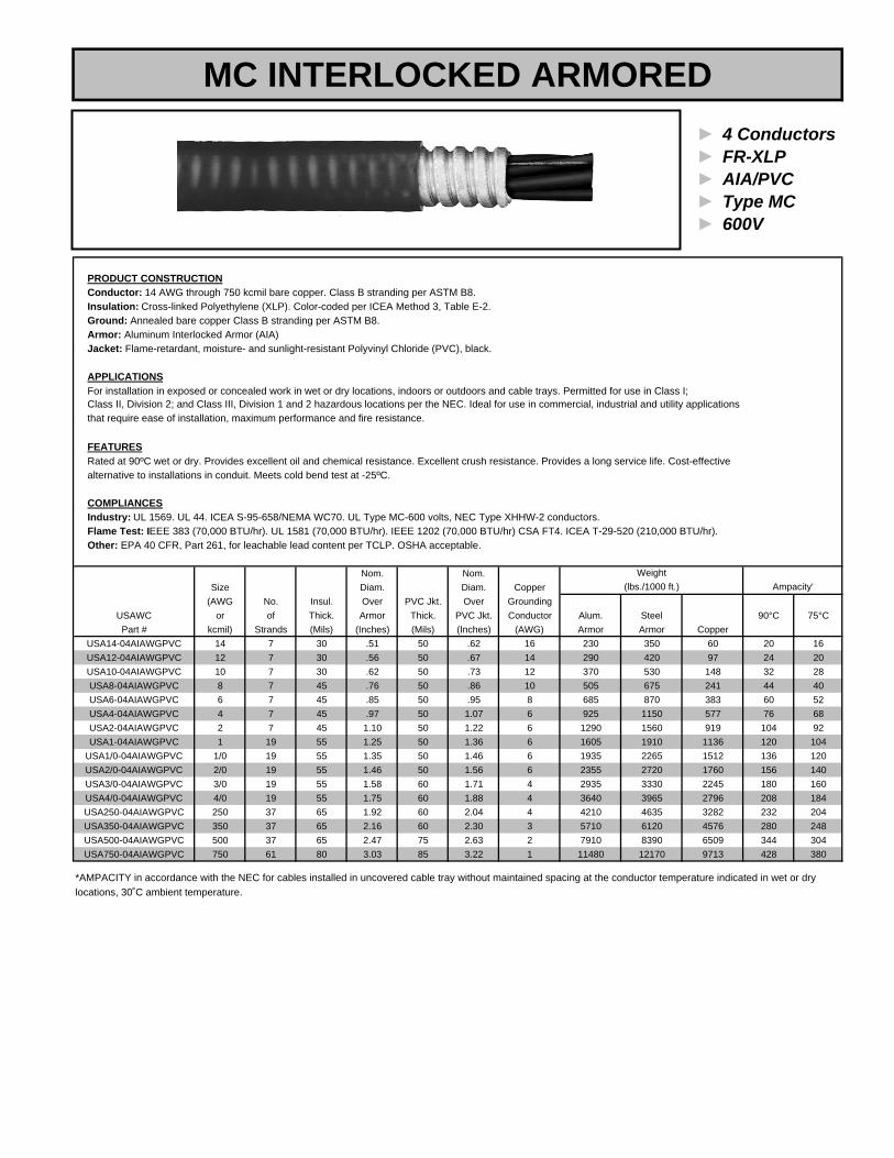
► 4 Conductors► FR-XLP► AIA/PVC► Type MC► 600V
PRODUCT CONSTRUCTIONConductor: 14 AWG through 750 kcmil bare copper. Class B stranding per ASTM B8.Insulation: Cross-linked Polyethylene (XLP). Color-coded per ICEA Method 3, Table E-2.Ground: Annealed bare copper Class B stranding per ASTM B8.Armor: Aluminum Interlocked Armor (AIA)Jacket: Flame-retardant, moisture- and sunlight-resistant Polyvinyl Chloride (PVC), black.
APPLICATIONSFor installation in exposed or concealed work in wet or dry locations, indoors or outdoors and cable trays. Permitted for use in Class I;
that require ease of installation, maximum performance and fire resistance.
FEATURESRated at 90ºC wet or dry. Provides excellent oil and chemical resistance. Excellent crush resistance. Provides a long service life. Cost-effectivealternative to installations in conduit. Meets cold bend test at -25ºC.
COMPLIANCESIndustry: UL 1569. UL 44. ICEA S-95-658/NEMA WC70. UL Type MC-600 volts, NEC Type XHHW-2 conductors.Flame Test: IEEE 383 (70,000 BTU/hr). UL 1581 (70,000 BTU/hr). IEEE 1202 (70,000 BTU/hr) CSA FT4. ICEA T-29-520 (210,000 BTU/hr).Other: EPA 40 CFR, Part 261, for leachable lead content per TCLP. OSHA acceptable.
Nom. Nom.Size Diam. Diam. Copper
(AWG No. Insul. Over PVC Jkt. Over GroundingUSAWC or of Thick. Armor Thick. PVC Jkt. Conductor Alum. Steel 90°C 75°CPart # kcmil) Strands (Mils) (Inches) (Mils) (Inches) (AWG) Armor Armor Copper
USA14-04AIAWGPVC 14 7 30 .51 50 .62 16 230 350 60 20 16USA12-04AIAWGPVC 12 7 30 .56 50 .67 14 290 420 97 24 20USA10-04AIAWGPVC 10 7 30 .62 50 .73 12 370 530 148 32 28USA8-04AIAWGPVC 8 7 45 .76 50 .86 10 505 675 241 44 40USA6-04AIAWGPVC 6 7 45 .85 50 .95 8 685 870 383 60 52USA4-04AIAWGPVC 4 7 45 .97 50 1.07 6 925 1150 577 76 68USA2-04AIAWGPVC 2 7 45 1.10 50 1.22 6 1290 1560 919 104 92USA1-04AIAWGPVC 1 19 55 1.25 50 1.36 6 1605 1910 1136 120 104
USA1/0-04AIAWGPVC 1/0 19 55 1.35 50 1.46 6 1935 2265 1512 136 120USA2/0-04AIAWGPVC 2/0 19 55 1.46 50 1.56 6 2355 2720 1760 156 140USA3/0-04AIAWGPVC 3/0 19 55 1.58 60 1.71 4 2935 3330 2245 180 160USA4/0-04AIAWGPVC 4/0 19 55 1.75 60 1.88 4 3640 3965 2796 208 184USA250-04AIAWGPVC 250 37 65 1.92 60 2.04 4 4210 4635 3282 232 204USA350-04AIAWGPVC 350 37 65 2.16 60 2.30 3 5710 6120 4576 280 248USA500-04AIAWGPVC 500 37 65 2.47 75 2.63 2 7910 8390 6509 344 304USA750-04AIAWGPVC 750 61 80 3.03 85 3.22 1 11480 12170 9713 428 380
Weight
Class II, Division 2; and Class III, Division 1 and 2 hazardous locations per the NEC. Ideal for use in commercial, industrial and utility applications
Ampacity'
locations, 30˚C ambient temperature.*AMPACITY in accordance with the NEC for cables installed in uncovered cable tray without maintained spacing at the conductor temperature indicated in wet or dry
(lbs./1000 ft.)
MC INTERLOCKED ARMORED
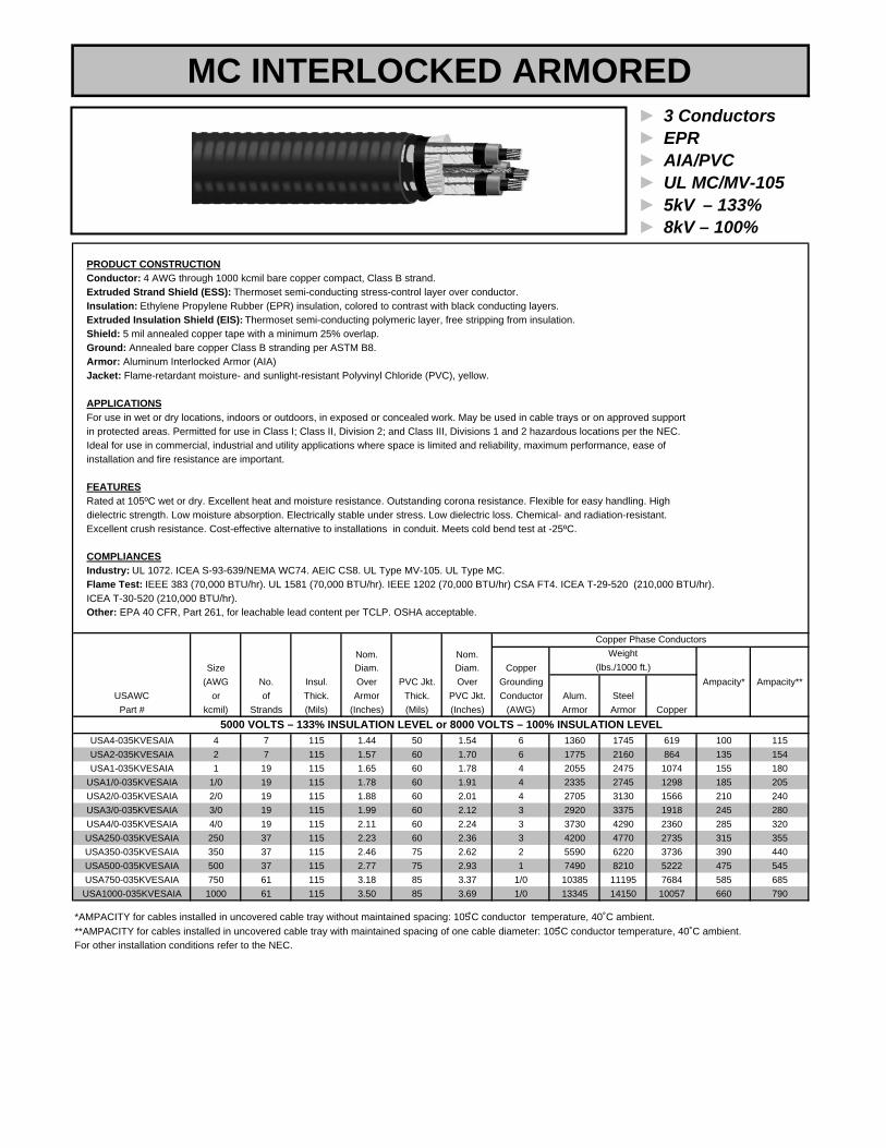
► 3 Conductors► EPR► AIA/PVC► UL MC/MV-105► 5kV – 133%► 8kV – 100%
PRODUCT CONSTRUCTIONConductor: 4 AWG through 1000 kcmil bare copper compact, Class B strand.Extruded Strand Shield (ESS): Thermoset semi-conducting stress-control layer over conductor.Insulation: Ethylene Propylene Rubber (EPR) insulation, colored to contrast with black conducting layers.Extruded Insulation Shield (EIS): Thermoset semi-conducting polymeric layer, free stripping from insulation.Shield: 5 mil annealed copper tape with a minimum 25% overlap.Ground: Annealed bare copper Class B stranding per ASTM B8.Armor: Aluminum Interlocked Armor (AIA)Jacket: Flame-retardant moisture- and sunlight-resistant Polyvinyl Chloride (PVC), yellow.
APPLICATIONSFor use in wet or dry locations, indoors or outdoors, in exposed or concealed work. May be used in cable trays or on approved support in protected areas. Permitted for use in Class I; Class II, Division 2; and Class III, Divisions 1 and 2 hazardous locations per the NEC. Ideal for use in commercial, industrial and utility applications where space is limited and reliability, maximum performance, ease ofinstallation and fire resistance are important.
FEATURESRated at 105ºC wet or dry. Excellent heat and moisture resistance. Outstanding corona resistance. Flexible for easy handling. High dielectric strength. Low moisture absorption. Electrically stable under stress. Low dielectric loss. Chemical- and radiation-resistant.Excellent crush resistance. Cost-effective alternative to installations in conduit. Meets cold bend test at -25ºC.
COMPLIANCESIndustry: UL 1072. ICEA S-93-639/NEMA WC74. AEIC CS8. UL Type MV-105. UL Type MC.Flame Test: IEEE 383 (70,000 BTU/hr). UL 1581 (70,000 BTU/hr). IEEE 1202 (70,000 BTU/hr) CSA FT4. ICEA T-29-520 (210,000 BTU/hr). ICEA T-30-520 (210,000 BTU/hr).Other: EPA 40 CFR, Part 261, for leachable lead content per TCLP. OSHA acceptable.
Nom. Nom.Size Diam. Diam. Copper
(AWG No. Insul. Over PVC Jkt. Over Grounding Ampacity* Ampacity**USAWC or of Thick. Armor Thick. PVC Jkt. Conductor Alum. SteelPart # kcmil) Strands (Mils) (Inches) (Mils) (Inches) (AWG) Armor Armor Copper
USA4-035KVESAIA 4 7 115 1.44 50 1.54 6 1360 1745 619 100 115USA2-035KVESAIA 2 7 115 1.57 60 1.70 6 1775 2160 864 135 154USA1-035KVESAIA 1 19 115 1.65 60 1.78 4 2055 2475 1074 155 180
USA1/0-035KVESAIA 1/0 19 115 1.78 60 1.91 4 2335 2745 1298 185 205USA2/0-035KVESAIA 2/0 19 115 1.88 60 2.01 4 2705 3130 1566 210 240USA3/0-035KVESAIA 3/0 19 115 1.99 60 2.12 3 2920 3375 1918 245 280USA4/0-035KVESAIA 4/0 19 115 2.11 60 2.24 3 3730 4290 2360 285 320USA250-035KVESAIA 250 37 115 2.23 60 2.36 3 4200 4770 2735 315 355USA350-035KVESAIA 350 37 115 2.46 75 2.62 2 5590 6220 3736 390 440USA500-035KVESAIA 500 37 115 2.77 75 2.93 1 7490 8210 5222 475 545USA750-035KVESAIA 750 61 115 3.18 85 3.37 1/0 10385 11195 7684 585 685
USA1000-035KVESAIA 1000 61 115 3.50 85 3.69 1/0 13345 14150 10057 660 790
(lbs./1000 ft.)
5000 VOLTS – 133% INSULATION LEVEL or 8000 VOLTS – 100% INSULATION LEVEL
*AMPACITY for cables installed in uncovered cable tray without maintained spacing: 105̊C conductor temperature, 40˚C ambient.
Copper Phase Conductors
**AMPACITY for cables installed in uncovered cable tray with maintained spacing of one cable diameter: 105̊C conductor temperature, 40˚C ambient.For other installation conditions refer to the NEC.
Weight
MC INTERLOCKED ARMORED

► 3 Conductors► EPR► AIA/PVC► UL MC/MV-105► 15kV – 133%
PRODUCT CONSTRUCTIONConductor: 2 AWG through 750 kcmil bare copper compact, Class B strand.Extruded Strand Shield (ESS): Thermoset semi-conducting stress-control layer over conductor.Insulation: Ethylene Propylene Rubber (EPR) insulation, colored to contrast with black conducting layers.Extruded Insulation Shield (EIS): Thermoset semi-conducting polymeric layer, free stripping from insulation.Shield: 5 mil annealed copper tape with a minimum 25% overlap.Ground: Annealed bare copper Class B stranding per ASTM B8.Armor: Aluminum Interlocked Armor (AIA)Jacket: Flame-retardant moisture- and sunlight-resistant Polyvinyl Chloride (PVC), red.
APPLICATIONSFor use in wet or dry locations, indoors or outdoors, in exposed or concealed work. May be used in cable trays or on approved support in protected areas. Permitted for use in Class I; Class II, Division 2; and Class III, Divisions 1 and 2 hazardous locations per the NEC. Ideal for use in commercial, industrial and utility applications where space is limited and reliability, maximum performance, ease ofinstallation and fire resistance are important.
FEATURESRated at 105ºC wet or dry. Excellent heat and moisture resistance. Outstanding corona resistance. Flexible for easy handling. High dielectric strength. Low moisture absorption. Electrically stable under stress. Low dielectric loss. Chemical- and radiation-resistant.Excellent crush resistance. Cost-effective alternative to installations in conduit. Meets cold bend test at -25ºC.
COMPLIANCESIndustry: UL 1072. ICEA S-93-639/NEMA WC74. AEIC CS8. UL Type MV-105. UL Type MC.Flame Test: IEEE 383 (70,000 BTU/hr). UL 1581 (70,000 BTU/hr). IEEE 1202 (70,000 BTU/hr) CSA FT4. ICEA T-29-520 (210,000 BTU/hr). ICEA T-30-520 (210,000 BTU/hr).Other: EPA 40 CFR, Part 261, for leachable lead content per TCLP. OSHA acceptable.
Nom. Nom.Size Nom. Diam. Diam. Copper
(AWG No. Insul. Diam. Over PVC Jkt. Over GroundingUSAWC or of Thick. Over Ins. Armor Thick. PVC Jkt. ConductorPart # kcmil) Strands (Mils) (Inches) (Inches) (Mils) (Inches) (AWG) Armor Armor Copper
USA2-0315KVESAIA 2 7 220 .78 2.11 60 2.24 6 2605 3125 919 165 185USA1-0315KVESAIA 1 19 220 .82 2.20 60 2.33 4 2835 3390 1125 185 210
USA1/0-0315KVESAIA 1/0 19 220 .86 2.28 60 2.41 4 3100 3620 1352 215 240USA2/0-0315KVESAIA 2/0 19 220 .91 2.39 75 2.55 4 3530 4025 1620 245 275USA3/0-0315KVESAIA 3/0 19 220 .96 2.50 75 2.66 3 3990 4510 1972 280 315USA4/0-0315KVESAIA 4/0 19 220 1.02 2.61 75 2.77 3 4615 5200 2114 320 360USA250-0315KVESAIA 250 37 220 1.07 2.79 75 2.95 3 5315 5895 2789 350 400USA350-0315KVESAIA 350 37 220 1.18 3.01 75 3.17 2 6600 7225 3790 430 490USA500-0315KVESAIA 500 37 220 1.30 3.29 85 3.47 1 8710 9350 5276 525 600USA750-0315KVESAIA 750 61 220 1.49 3.67 85 3.85 1/0 11695 12850 7738 635 745
*AMPACITY for cables installed in uncovered cable tray without maintained spacing: 105̊C conductor temperature, 40˚C ambient.**AMPACITY for cables installed in uncovered cable tray with maintained spacing of one cable diameter: 105̊C conductor temperature, 40˚C ambient.For other installation conditions refer to the NEC.
15000 VOLTS, 133% INSULATION LEVEL
Ampacity*SteelAlum.
Weight
Ampacity**(lbs./1000 ft.)
MC INTERLOCKED ARMORED
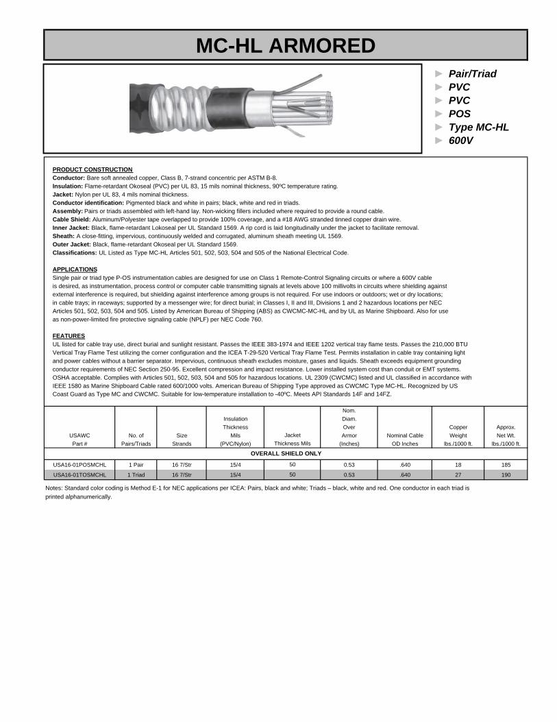
► Pair/Triad► PVC► PVC► POS► Type MC-HL► 600V
PRODUCT CONSTRUCTIONConductor: Bare soft annealed copper, Class B, 7-strand concentric per ASTM B-8.Insulation: Flame-retardant Okoseal (PVC) per UL 83, 15 mils nominal thickness, 90ºC temperature rating.Jacket: Nylon per UL 83, 4 mils nominal thickness.Conductor identification: Pigmented black and white in pairs; black, white and red in triads.Assembly: Pairs or triads assembled with left-hand lay. Non-wicking fillers included where required to provide a round cable.Cable Shield: Aluminum/Polyester tape overlapped to provide 100% coverage, and a #18 AWG stranded tinned copper drain wire.Inner Jacket: Black, flame-retardant Lokoseal per UL Standard 1569. A rip cord is laid longitudinally under the jacket to facilitate removal.Sheath: A close-fitting, impervious, continuously welded and corrugated, aluminum sheath meeting UL 1569.Outer Jacket: Black, flame-retardant Okoseal per UL Standard 1569.Classifications: UL Listed as Type MC-HL Articles 501, 502, 503, 504 and 505 of the National Electrical Code.
APPLICATIONSSingle pair or triad type P-OS instrumentation cables are designed for use on Class 1 Remote-Control Signaling circuits or where a 600V cableis desired, as instrumentation, process control or computer cable transmitting signals at levels above 100 millivolts in circuits where shielding againstexternal interference is required, but shielding against interference among groups is not required. For use indoors or outdoors; wet or dry locations; in cable trays; in raceways; supported by a messenger wire; for direct burial; in Classes I, II and III, Divisions 1 and 2 hazardous locations per NEC Articles 501, 502, 503, 504 and 505. Listed by American Bureau of Shipping (ABS) as CWCMC-MC-HL and by UL as Marine Shipboard. Also for use as non-power-limited fire protective signaling cable (NPLF) per NEC Code 760.
FEATURESUL listed for cable tray use, direct burial and sunlight resistant. Passes the IEEE 383-1974 and IEEE 1202 vertical tray flame tests. Passes the 210,000 BTU Vertical Tray Flame Test utilizing the corner configuration and the ICEA T-29-520 Vertical Tray Flame Test. Permits installation in cable tray containing lightand power cables without a barrier separator. Impervious, continuous sheath excludes moisture, gases and liquids. Sheath exceeds equipment groundingconductor requirements of NEC Section 250-95. Excellent compression and impact resistance. Lower installed system cost than conduit or EMT systems.OSHA acceptable. Complies with Articles 501, 502, 503, 504 and 505 for hazardous locations. UL 2309 (CWCMC) listed and UL classified in accordance withIEEE 1580 as Marine Shipboard Cable rated 600/1000 volts. American Bureau of Shipping Type approved as CWCMC Type MC-HL. Recognized by USCoast Guard as Type MC and CWCMC. Suitable for low-temperature installation to -40ºC. Meets API Standards 14F and 14FZ.
Nom.Insulation Diam.Thickness Over Copper Approx.
USAWC No. of Size Mils Armor Nominal Cable Weight Net Wt.Part # Pairs/Triads Strands (PVC/Nylon) (Inches) OD Inches lbs./1000 ft. lbs./1000 ft.
USA16-01POSMCHL 1 Pair 16 7/Str 15/4 0.53 .640 18 185
USA16-01TOSMCHL 1 Triad 16 7/Str 15/4 0.53 .640 27 190
printed alphanumerically.Notes: Standard color coding is Method E-1 for NEC applications per ICEA: Pairs, black and white; Triads – black, white and red. One conductor in each triad is
50
JacketThickness Mils
50
OVERALL SHIELD ONLY
MC-HL ARMORED

► Pairs/Triads► PVC/Nylon► PVC► SPOS/STOS► Type MC-HL► 600V
PRODUCT CONSTRUCTIONConductor: Bare soft annealed copper, Class B, 7-strand concentric per ASTM B-8.Insulation: Flame-retardant Okoseal (PVC) per UL 83, 15 mils nominal thickness, 90ºC temperature rating.Jacket: Nylon per UL 83, 4 mils nominal thickness.Conductor identification: Pigmented black and white in pairs; black, white and red in triads.Assembly: Pairs or triads assembled with left-hand lay. Non-wicking fillers included where required to provide a round cable.Cable Shield: Aluminum/Polyester tape overlapped to provide 100% coverage, and a #18 AWG stranded tinned copper drain wire.Inner Jacket: Black, flame-retardant Lokoseal per UL Standard 1569. A rip cord is laid longitudinally under the jacket to facilitate removal.Sheath: A close-fitting, impervious, continuously welded and corrugated, aluminum sheath meeting UL 1569.Outer Jacket: Black, flame-retardant Okoseal per UL Standard 1569.Classifications: UL Listed as Type MC-HL Articles 501, 502, 503, 504 and 505 of the National Electrical Code.
APPLICATIONSSingle pair or triad type P-OS instrumentation cables are designed for use on Class 1 Remote-Control Signaling circuits or where a 600V cableis desired, as instrumentation, process control or computer cable transmitting signals at levels above 100 millivolts in circuits where shielding againstexternal interference is required, but shielding against interference among groups is not required. For use indoors or outdoors; wet or dry locations; in cable trays; in raceways; supported by a messenger wire; for direct burial; in Classes I, II and III, Divisions 1 and 2 hazardous locations per NEC Articles 501, 502, 503, 504 and 505. Listed by American Bureau of Shipping (ABS) as CWCMC-MC-HL and by UL as Marine Shipboard. Also for use as non-power-limited fire protective signaling cable (NPLF) per NEC Code 760.
FEATURESUL listed for cable tray use, direct burial and sunlight resistant. Passes the IEEE 383-1974 and IEEE 1202 vertical tray flame tests. Passes the 210,000 BTU Vertical Tray Flame Test utilizing the corner configuration and the ICEA T-29-520 Vertical Tray Flame Test. Permits installation in cable tray containing lightand power cables without a barrier separator. Impervious, continuous sheath excludes moisture, gases and liquids. Sheath exceeds equipment groundingconductor requirements of NEC Section 250-95. Excellent compression and impact resistance. Lower installed system cost than conduit or EMT systems.OSHA acceptable. Complies with Articles 501, 502, 503, 504 and 505 for hazardous locations. UL 2309 (CWCMC) listed and UL classified in accordance withIEEE 1580 as Marine Shipboard Cable rated 600/1000 volts. American Bureau of Shipping Type approved as CWCMC Type MC-HL. Recognized by USCoast Guard as Type MC and CWCMC. Suitable for low-temperature installation to -40ºC. Meets API Standards 14F and 14FZ.
Nom.Insulation Diam.Thickness Over Copper Approx.
USAWC No. of Size (Mils) Armor Nominal Cable Weight Net Wt.Part # Pairs/Triads Strands (PVC/Nylon) (Inches) OD (Inches) (lbs./1000 ft.) (lbs./1000 ft.)
USA16-02SPOSMCHL 2 Pairs 16 7/Str 15/4 0.67 0.76 42 234USA16-04SPOSMCHL 4 Pairs 16 7/Str 15/4 0.80 0.91 80 335USA16-06SPOSMCHL 6 Pairs 16 7/Str 15/4 0.89 1.00 116 421USA16-08SPOSMCHL 8 Pairs 16 7/Str 15/4 0.93 1.04 155 492USA16-10SPOSMCHL 10 Pairs 16 7/Str 15/4 1.06 1.17 192 601USA16-12SPOSMCHL 12 Pairs 16 7/Str 15/4 1.11 1.22 230 674USA16-16SPOSMCHL 16 Pairs 16 7/Str 15/4 1.29 1.40 306 842USA16-20SPOSMCHL 20 Pairs 16 7/Str 15/4 1.34 1.45 375 977USA16-24SPOSMCHL 24 Pairs 16 7/Str 15/4 1.42 1.53 456 1118USA16-36SPOSMCHL 36 Pairs 16 7/Str 15/4 1.69 1.82 674 1586USA16-50SPOSMCHL 50 Pairs 16 7/Str 15/4 1.92 2.05 935 2124
USA16-04STOSMCHL 4 Triads 16 7/Str 15/4 0.84 0.95 108 395USA16-08STOSMCHL 8 Triads 16 7/Str 15/4 1.06 1.17 218 637USA16-12STOSMCHL 12 Triads 16 7/Str 15/4 1.29 1.40 325 863USA16-16STOSMCHL 16 Triads 16 7/Str 15/4 1.37 1.48 433 1058USA16-24STOSMCHL 24 Triads 16 7/Str 15/4 1.64 1.78 649 1485USA16-36STOSMCHL 36 Triads 16 7/Str 15/4 1.96 2.09 972 2141
printed alphanumerically.
InnerJacket
Thickness (Mils)16 AWG – INDIVIDUAL AND OVERALL SHIELD
50
50
50
5050
505050
50
5050
Notes: Standard color coding is Method E-1 for NEC applications per ICEA: Pairs, black and white; Triads – black, white and red. One conductor in each triad is
505050505050
MC-HL ARMORED
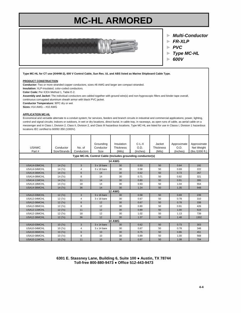
► Multi-Conductor► FR-XLP► PVC► Type MC-HL► 600V
Type MC-HL for CT use (XHHW-2), 600 V Control Cable, Sun Res. UL and ABS listed as Marine Shipboard Cable Type.
PRODUCT CONSTRUCTIONConductor: Two or more stranded copper conductors, sizes #8 AWG and larger are compact stranded.Insulation: XLP-insulated, color-coded conductors.Color Code: Per ICEA Method 1, Table E-2.Assembly and Jacket: The individual conductors are cabled together with ground wire(s) and non-hygroscopic fillers and binder tape overall,continuous corrugated aluminum sheath armor with black PVC jacket.Conductor Temperature: 90ºC dry or wetSizes: #14 AWG – #10 AWG
APPLICATION MC-HLEconomical and versatile alternate to a conduit system; for services, feeders and branch circuits in industrial and commercial applications; power, lighting, control and signal circuits; indoors or outdoors, in wet or dry locations, direct burial, in cable tray, in raceways, as open runs of cable, as aerial cable on a messenger and in Class I, Division 2, Class II, Division 2, and Class III hazardous locations. Type MC-HL are listed for use in Classs I, Division 1 hazardouslocations IEC certified to 60092-350 (1000V).
Grounding Insulation C-L-X Jacket Approximate ApproximateUSAWC Conductor No. of Conductor Thickness O.D. Thickness O.D. Net WeightPart # Size/Strands Conductors Size (Mils) (Inches) (Mils) (Inches) (lbs./1000 ft.)
MC-HL ARMORED
USA14-03MCHL 14 (7x) 3 3 x 18 bare 30 0.53 50 0.64 192USA14-04MCHL 14 (7x) 4 3 x 18 bare 30 0.58 50 0.69 222USA14-06MCHL 14 (7x) 6 14 30 0.62 50 0.73 267USA14-08MCHL 14 (7x) 8 14 30 0.71 50 0.82 321USA14-11MCHL 14 (7x) 11 14 30 0.80 50 0.91 395USA14-18MCHL 14 (7x) 18 14 30 0.93 50 1.04 554USA14-36MCHL 14 (7x) 36 14 30 1.24 50 1.35 948
USA12-03MCHL 12 (7x) 3 3 x 16 bare 30 0.58 50 0.69 239USA12-04MCHL 12 (7x) 4 3 x 18 bare 30 0.67 50 0.78 310USA12-06MCHL 12 (7x) 6 12 30 0.67 50 0.78 338USA12-08MCHL 12 (7x) 8 12 30 0.80 50 0.91 426USA12-11MCHL 12 (7x) 11 12 30 0.89 50 1.00 519USA12-18MCHL 12 (7x) 18 12 30 1.02 50 1.13 739USA12-36MCHL 12 (7x) 36 12 30 1.37 50 1.48 1302
USA10-03MCHL 10 (7x) 3 3 x 14 bare 30 0.62 50 0.73 303USA10-04MCHL 10 (7x) 4 3 x 14 bare 30 0.67 50 0.78 348USA10-06MCHL 10 (7x) 6 10 30 0.75 50 0.86 451USA10-08MCHL 10 (7x) 8 10 30 0.89 50 1.00 568USA10-11MCHL 10 (7x) 11 10 30 0.97 50 1.08 704
10 AWG
14 AWG
Type MC-HL Control Cable (Includes grounding conductor(s)
12 AWG
6301 E. Stassney Lane, Building 6, Suite 100 ● Austin, TX 78744Toll-free 800-880-9473 ● Office 512-443-9473
4-4

► 3C and 4C► FR-XLP► PVC► Type MC-HL► 600V
Type MC-HL for CT use (XHHW-2), 600 V Control Cable, Sun Res. UL and ABS listed as Marine Shipboard Cable Type.
PRODUCT CONSTRUCTIONConductor: Two or more stranded copper conductors, sizes #8 AWG and larger are compact stranded.Insulation: XLP-insulated, color-coded conductors, ground wire (MC-HL only), fillers (as necessary), binder tape over core,corrugated aluminum sheath with PVC jacket overall.Conductor Temperature: 90ºC dry or wetSizes: #14 AWG – 750 kcmil
APPLICATION MC-HLThree symmetrical grounding conductors for PWM/VFD and other modern AC drive/motor applications. Economical and versatile alternate to a conduit system; for services, feeders and branch circuits in industrial and commercial applications; power, lighting, control and signal circuits;indoors or outdoors, in wet or dry locations, direct burial, in cable tray, in raceways, as open runs of cable, as aerial cable on a messenger and in Class I, II and III, Division 1 and 2 hazardous locations. Recommended for VFD/PWM drives. IEC certified to 60092-350 (1000 V).
Conductor Size* Grounding Insulation Nom. Diam. Jacket Approximate ApproximateUSAWC (AWG or kcmil) No. of Conductor** Thickness Over Armor Thickness O.D. Net WeightPart # and Strands Conductors Size (Mils) (Inches) (Mils) (Inches) (lbs./1000 ft.)
USA14-03MCHL 14 (7x) 3 3 x 18 30 0.53 50 0.64 160USA14-04MCHL 14 (7x) 4 3 x 18 30 0.58 50 0.69 222USA12-03MCHL 12 (7x) 3 3 x 16 30 0.58 50 0.69 239USA12-04MCHL 12 (7x) 4 3 x 16 30 0.67 50 0.77 310USA10-03MCHL 10 (7x) 3 3 x 14 30 0.62 50 0.73 303USA10-04MCHL 10 (7x) 4 3 x 14 30 0.67 50 0.78 348
MC-HL ARMORED
( )USA8-03MCHL 8 (7x) 3 3 x 14 45 0.71 50 0.82 405USA8-04MCHL 8 (7x) 4 10 45 0.80 50 0.91 480USA6-03MCHL 6 (7x) 3 3 x 12 45 0.80 50 0.95 500USA6-04MCHL 6 (7x) 4 8 45 0.89 50 0.99 650USA4-03MCHL 4 (7x) 3 3 x 12 45 0.89 50 0.99 735USA4-04MCHL 4 (7x) 4 8 45 0.97 50 1.08 875USA2-03MCHL 2 (7x) 3 3 x 10 45 1.02 50 1.13 1035USA2-04MCHL 2 (7x) 4 6 45 1.15 50 1.26 1310
USA1/0-03MCHL 1/0 (19x) 3 3 x 10 55 1.24 50 1.35 1460USA1/0-04MCHL 1/0 (19x) 4 6 55 1.37 50 1.48 1830USA2/0-03MCHL 2/0 (19x) 3 3 x 10 55 1.34 50 1.45 1770USA2/0-04MCHL 2/0 (19x) 4 6 55 1.51 60 1.65 2425USA4/0-03MCHL 4/0 (19x) 3 3 x 8 55 1.60 60 1.73 2795USA4/0-04MCHL 4/0 (19x) 4 4 55 1.78 60 1.91 3520USA250-03MCHL 250 (37x) 3 3 x 8 65 1.74 60 1.87 3325USA250-04MCHL 250 (37x) 4 4 65 1.96 60 2.09 4070USA350-03MCHL 350 (37x) 3 3 x 7 65 1.96 60 2.09 4315USA350-04MCHL 350 (37x) 4 3 65 2.19 60 2.32 5380USA500-03MCHL 500 (37x) 3 3 x 6 65 2.28 75 2.44 5792USA500-04MCHL 500 (37x) 4 2 65 2.49 75 2.65 7520USA750-03MCHL 750 (61x) 3 3 x 5 80 2.75 75 2.92 8575
*#8 and larger is compact round conductor. Conductor Identification: Surface printing of numbers and colors per ICEA Method 3 – sizes #4 AWG and larger;sizes #6 and smaller, Method 1, E-2. **Minimum size. UL permits partitioning of grounding conductor; grounds are bare.
Type MC and MC-HL Conductor Identification: Surface printing of numbers and colors per ICEA Method 3 – sizes #4 AWG and larger;sizes #6 and smaller, Method 1, E-2. *Minimum size. UL permits partitioning of grounding conductor; grounds are bare.
Three Symmetrical Grounding Conductors for PWM and Other Modern AC Drive/Motor Applications
Power Insulation Control Insulation Nom. Diam. Grounding Jacket Approximate ApproximateUSAWC Conductors Thickness Conductors Thickness Over Armor Conductor* Thickness O.D. Net WeightPart # No. x Size (Mils) No. x Size (Mils) (Inches) No. x Size (Mils) (Inches) (lbs./1000 ft.)
USA10-3+12-4-03MCHL 3 x 10 30 4 x 12 30 0.75 1 x 10 50 0.86 400USA8-3+12-4-03MCHL 3 x 8 45 4 x 12 30 0.89 3 x 10 50 1.00 530USA6-3+12-4-03MCHL 3 x 6 45 4 x 12 30 0.93 1 x 8 50 1.04 685USA4-3+12-4-03MCHL 3 x 4 45 4 x 12 30 0.97 1 x 8 50 1.08 860
Composite Power & Control Cables

► 3 Conductors► EPR► PVC► MC-HL/MV-105► 5kV – 133%► 8kV – 100%
PRODUCT CONSTRUCTIONConductor: 6 AWG through 1000 kcmil bare annealed copper per ASTM B3. Compact stranding per ASTM B496. Extruded Strand Shield (ESS): Extruded thermoset semi-conductor stress control layer over the conductor per ICEA S-93-639 and UL 1072.Insulation: 115 mil Ethylene Propylene Rubber (EPR) insulation per ICEA S-93-639 and UL 1072.Extruded Insulation Shield (EIS): Thermoset semi-conducting polymeric layer, free stripping from the insulation per ICEA S-93-639 and UL 1072.Shield: 5 mil annealed bare copper tape with 25% overlap.Grounding Conductor(s): Three split Class B stranded bare annealed copper ground conductors sized in accordance with UL 1072 and NEC Article 250.Armor: Impervious, continuously welded and corrugated aluminum alloy sheath per UL 1072 and 1569. Meets grounding requirements of NEC Article 250. Jacket: Flame-retardant, moisture- and sunlight-resistant Polyvinyl Chloride (PVC), yellow. Low-temperature performance meets ASTM D746 brittlenesstemperature at or below -40ºC.
APPLICATIONSVariable Frequency Drives: 3-conductor CCW armored cables with three symmetrical grounding wires are the preferred wiring method for use with AC motors controlled by pulse-width modulated inverters in VFD applications. For use in Class I, II and III, Divisions 1 and 2; or Class 1, Zones 1 and 2 hazardous locations per NEC Articles 501, 502, 503 and 505. For installation on metal racks, troughs, in raceways and cable trays, or secured to supports not more than six feet apart. For exposed and concealed work in wet or dry locations, directly buried or embedded in concrete. For use on feeders and branch circuits in industrial power distribution systems per NEC Articles 328 and 330.
FEATURESArmor provides impervious barrier to moisture, gas and liquids. The strand shield, EPR insulation and insulation shield are extruded in one operation. The EPR insulation system has outstanding corona resistance and high dielectric strength, and it provides electrical stability under stress.Meets cold impact test at -40ºC.
COMPLIANCESIndustry: UL Type MV-105. UL Type MC-HL, XHHW-2, CT USE, SUN RES, DIR BUR -40ºC, FT4. UL Listed Marine Shipboard, American Bureau of Shipping (ABS) Listed for CWCMC.Design Adherence: ICEA S-93-639/WC74, 5-46 kV Shielded Power Cable. AEIC CS8 Specification for Shielded Power Cable, 5-46 kV. UL 1072 Medium-Voltage Power Cables. UL 1569 Metal Clad Cables. UL 2225 Cables and Cable Fittings for Use in Hazardous Locations.UL 1309 Marine Shipboard Cable. CSA C68.3Flame Tests: ICEA T-29-520 (210,000 BTU/hr). IEEE 383 (70,000 BTU/hr). CSA FT4. IEEE 1202 (70,000 BTU/hr). UL 1072. IEC 60332-3 Category A.
Nom. Nom.Size Diam. Diam. Copper
(AWG No. Insul. Over PVC Jkt. Over GroundingUSAWC or of Thick. Armor Thick PVC Jkt. Conductor DirectPart # kcmil) Strands (Mils) (Inches) (Mils) (Inches) (AWG) Net Copper In Air Burial
USA6-035KVMCHL 6 7 115 1.37 50 1.48 3 X #10 1121 460 88 115USA4-035KVMCHL 4 7 115 1.51 60 1.65 3 X #10 1418 616 115 150USA2-035KVMCHL 2 7 115 1.64 60 1.78 3 X #10 1731 860 154 190USA1-035KVMCHL 1 19 115 1.69 60 1.82 3 X #8 1978 1074 180 215
USA1/0-035KVMCHL 1/0 19 115 1.78 60 1.91 3 X #8 2259 1290 205 245USA2/0-035KVMCHL 2/0 19 115 1.92 60 2.05 3 X #8 2626 1556 240 280USA4/0-035KVMCHL 4/0 19 115 2.15 60 2.28 3 X #7 3650 2344 320 360USA250-035KVMCHL 250 37 115 2.23 60 2.36 3 X #7 4060 2759 355 395USA350-035KVMCHL 350 37 115 2.45 75 2.61 3 X #6 5045 3713 440 475USA500-035KVMCHL 500 37 115 2.75 75 2.92 3 X #5 7137 5191 545 570USA750-035KVMCHL 750 61 115 3.32 85 3.50 3 X #4 10268 7629 685 700
USA1000-035KVMCHL 1000 61 115 3.76 85 3.94 3 X #4 13051 10070 790 785
Weight(lbs./1000 ft.)
Copper Phase Conductors
5000 VOLTS – 133% INSULATION LEVEL or 8000 VOLTS – 100% INSULATION LEVEL
Ampacity
MC-HL ARMORED
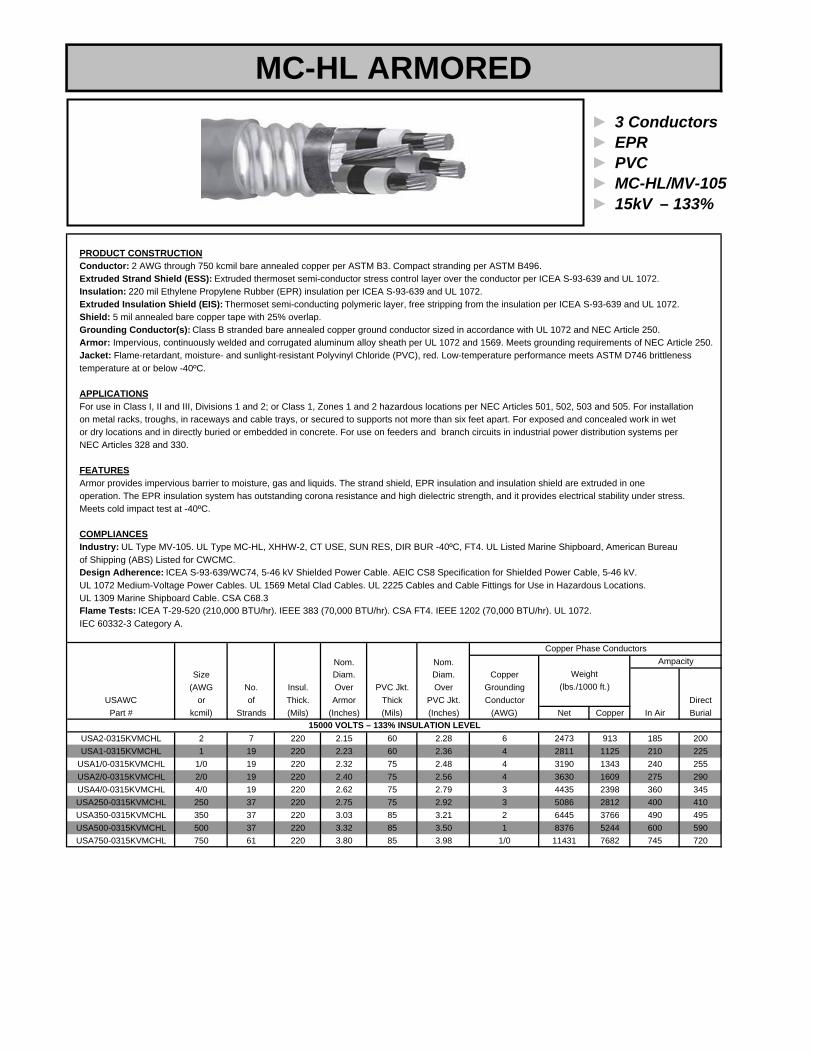
► 3 Conductors► EPR► PVC► MC-HL/MV-105► 15kV – 133%
PRODUCT CONSTRUCTIONConductor: 2 AWG through 750 kcmil bare annealed copper per ASTM B3. Compact stranding per ASTM B496. Extruded Strand Shield (ESS): Extruded thermoset semi-conductor stress control layer over the conductor per ICEA S-93-639 and UL 1072.Insulation: 220 mil Ethylene Propylene Rubber (EPR) insulation per ICEA S-93-639 and UL 1072.Extruded Insulation Shield (EIS): Thermoset semi-conducting polymeric layer, free stripping from the insulation per ICEA S-93-639 and UL 1072.Shield: 5 mil annealed bare copper tape with 25% overlap.Grounding Conductor(s): Class B stranded bare annealed copper ground conductor sized in accordance with UL 1072 and NEC Article 250.Armor: Impervious, continuously welded and corrugated aluminum alloy sheath per UL 1072 and 1569. Meets grounding requirements of NEC Article 250. Jacket: Flame-retardant, moisture- and sunlight-resistant Polyvinyl Chloride (PVC), red. Low-temperature performance meets ASTM D746 brittlenesstemperature at or below -40ºC.
APPLICATIONSFor use in Class I, II and III, Divisions 1 and 2; or Class 1, Zones 1 and 2 hazardous locations per NEC Articles 501, 502, 503 and 505. For installationon metal racks, troughs, in raceways and cable trays, or secured to supports not more than six feet apart. For exposed and concealed work in wet or dry locations and in directly buried or embedded in concrete. For use on feeders and branch circuits in industrial power distribution systems per NEC Articles 328 and 330.
FEATURESArmor provides impervious barrier to moisture, gas and liquids. The strand shield, EPR insulation and insulation shield are extruded in one operation. The EPR insulation system has outstanding corona resistance and high dielectric strength, and it provides electrical stability under stress.Meets cold impact test at -40ºC.
COMPLIANCESIndustry: UL Type MV-105. UL Type MC-HL, XHHW-2, CT USE, SUN RES, DIR BUR -40ºC, FT4. UL Listed Marine Shipboard, American Bureauof Shipping (ABS) Listed for CWCMC.Design Adherence: ICEA S-93-639/WC74, 5-46 kV Shielded Power Cable. AEIC CS8 Specification for Shielded Power Cable, 5-46 kV. UL 1072 Medium-Voltage Power Cables. UL 1569 Metal Clad Cables. UL 2225 Cables and Cable Fittings for Use in Hazardous Locations.UL 1309 Marine Shipboard Cable. CSA C68.3Flame Tests: ICEA T-29-520 (210,000 BTU/hr). IEEE 383 (70,000 BTU/hr). CSA FT4. IEEE 1202 (70,000 BTU/hr). UL 1072. IEC 60332-3 Category A.
Nom. Nom.Size Diam. Diam. Copper
(AWG No. Insul. Over PVC Jkt. Over GroundingUSAWC or of Thick. Armor Thick PVC Jkt. Conductor DirectPart # kcmil) Strands (Mils) (Inches) (Mils) (Inches) (AWG) Net Copper In Air Burial
USA2-0315KVMCHL 2 7 220 2.15 60 2.28 6 2473 913 185 200USA1-0315KVMCHL 1 19 220 2.23 60 2.36 4 2811 1125 210 225
USA1/0-0315KVMCHL 1/0 19 220 2.32 75 2.48 4 3190 1343 240 255USA2/0-0315KVMCHL 2/0 19 220 2.40 75 2.56 4 3630 1609 275 290USA4/0-0315KVMCHL 4/0 19 220 2.62 75 2.79 3 4435 2398 360 345USA250-0315KVMCHL 250 37 220 2.75 75 2.92 3 5086 2812 400 410USA350-0315KVMCHL 350 37 220 3.03 85 3.21 2 6445 3766 490 495USA500-0315KVMCHL 500 37 220 3.32 85 3.50 1 8376 5244 600 590USA750-0315KVMCHL 750 61 220 3.80 85 3.98 1/0 11431 7682 745 720
15000 VOLTS – 133% INSULATION LEVEL
Copper Phase Conductors
Weight(lbs./1000 ft.)
Ampacity
MC-HL ARMORED

► Multi-Conductor► XLP► PVC► Type MC► 600V
Type MC for CT use (XHHW-2), 600 V Control Cable, Sun Res. UL and ABS listed as Marine Shipboard Cable Type
PRODUCT CONSTRUCTIONConductor: Two or more stranded copper conductors, sizes #8 AWG and larger are compact stranded.Insulation: XLP-insulated, color-coded conductors. Color Code: Per ICEA Method 1, Table E-2. Assembly and Jacket: The individual conductors are cabled together with non-hygroscopic fillers and binder tape overall, continuous corrugatedaluminum sheath armor with black PVC jacket overall.Conductor Temperature: 90ºC dry or wetSizes: #14 AWG – #10 AWG
APPLICATION MCEconomical and versatile alternate to a conduit system; for services, feeders and branch circuits in industrial and commercial applications; power, lighting, control and signal circuits; indoors or outdoors, in wet or dry locations, direct burial, in cable tray, in raceways, as open runs of cable, as aerial cable on a messenger and in Class I, Division 2; Class II, Division 2; and Class III hazardous locations.
Nom.Diam.
Insulat. Over Jacket ApproximateUSAWC Conductor No. of Thick. Armor Thick. O.D. WeightPart # Size/Strands Conductors (Mils) (Inches) (Mils) (Inches) (lbs./ 1000 ft.)
USA14-03CCS 14 (7x) 3 30 0.49 50 0.60 153USA14-04CCS 14 (7x) 4 30 0.53 50 0.64 181USA14-05CCS 14 (7x) 5 30 0.58 50 0.69 210USA14-07CCS 14 (7x) 7 30 0.62 50 0.73 254USA14-09CCS 14 (7x) 9 30 0.71 50 0.82 308USA14-12CCS 14 (7x) 12 30 0.80 50 0.91 381USA14-19CCS 14 (7x) 19 30 0.93 50 1.04 537USA14-37CCS 14 (7x) 37 30 1.24 50 1.35 946
USA12-03CCS 12 (7x) 3 30 0.53 50 0.64 189USA12-04CCS 12 (7x) 4 30 0.58 50 0.69 226USA12-05CCS 12 (7x) 5 30 0.62 50 0.73 262USA12-07CCS 12 (7x) 7 30 0.67 50 0.78 324USA12-09CCS 12 (7x) 9 30 0.80 50 0.91 405USA12-12CCS 12 (7x) 12 30 0.89 50 1.00 503USA12-19CCS 12 (7x) 19 30 1.02 50 1.13 721USA12-37CCS 12 (7x) 37 30 1.37 50 1.48 1301
USA10-03CCS 10 (7x) 3 30 0.58 50 0.69 238USA10-04CCS 10 (7x) 4 30 0.67 50 0.78 297USA10-07CCS 10 (7x) 7 30 0.75 50 0.86 436
10 AWG
14 AWGType MC Control Cable (does not include grounding conductor)
12 AWG
MC CONTINUOUS ARMORED

WIRE GAGE TABLECONCENTRIC STRANDED CLASS B COPPER AND ALUMINUM CONDUCTORS
Nominal SizeConductor Number Diameter Outside Diameter
CMIL of Wires of Wires in inchesAWG
3,000,000 9353 2843 169 .1332 1.9982,500,000 7794 2369 127 .1403 1.8242,000,000 6175 1877 127 .1255 1.6321,750,000 5403 1642 127 .1174 1.5261,500,000 4631 1408 91 .1284 1.4121,250,000 3859 1173 91 .1172 1.2891,000,000 3088 938.7 61 .1280 1.152900,000 2779 844.8 61 .1215 1.094800,000 2470 750.9 61 .1145 1.031795,000 2466 749.8 61 .1142 1.028750,000 2316 704.1 61 .1109 .998700,000 2161 656.9 61 .1071 .964650,000 2007 610.1 61 .1032 .929600,000 1853 563.3 61 .0992 .893550,000 1698 516.2 61 .0950 .855500,000 1544 469.4 37 .1162 .813450,000 1389 422.3 37 .1103 .772400,000 1235 375.5 37 .1040 .728397,500 1228 373.2 37 .1037 .726350,000 1081 328.6 37 .0973 .681300,000 926.3 281.6 37 .0900 .630250,000 771.9 234.7 37 .0822 .575
0000 653.3 198.6 19 .1055 .528000 S18.1 157.5 19 .0940 .47000 410.9 124.9 19 .0837 .4190 325.8 99.04 19 .0745 .3731 258.4 78.55 19 .0664 .3322 204.9 62.29 7 .0974 .2923 162.5 49.40 7 .0867 .2604 128.9 39.19 7 .0772 .2325 102.2 31.07 7 .0688 .2066 81.05 24.64 7 .0612 .1847 64.28 19.54 7 .0545 .1648 50.97 15.49 7 .0486 .1469 40.42 12.29 7 .0432 .13010 32.06 9.746 7 .0385 .11612 20.16 6.129 7 .0305 .091514 12.68 3.855 7 .0242 .072616 7.974 2.424 7 .0192 .057618 5.015 1.525 7 .0152 .045620 3.154 0.9588 7 .0121 .0363
lbs/1000 ft.
AluminumCopper

METRIC CONDUCTORSSize and Stranding
1 7 1.29 .050 6.09 127 250 37 14.61 .575 772
1.31 16 7 1.47 .058 8.00 150 19 15.85 .624 914
1.5 7 1.56 .062 9.14 152 300 37 16.00 .630 926
2.08 14 7 1.85 .073 12.70 177 350 37 17.30 .681 1081
2.5 7 2.01 .080 15.23 185 19 17.60 .693 1127
3.31 12 7 2.34 .092 20.12 185 37 17.64 .695 1127
4.0 7 2.55 .101 24.37 203 400 37 18.49 .728 1235
5.26 10 7 2.95 .116 32.10 240 19 20.05 .790 1462
6.0 7 3.12 .123 36.56 240 37 20.09 .792 1462
8.37 8 7 3.71 .146 51.00 253.4 500 37 20.65 .813 1544
10.0 7 4.05 .160 60.93 280 37 21.70 .855 1706
13.30 6 7 4.67 .184 81.00 304 600 61 22.68 .893 1853
16 7 5.13 .202 97.49 310 37 22.89 .902 1889
21.15 4 7 5.89 .232 129.00 355 37 24.50 .963 2163
25 7 6.39 .252 152.30 380 750 61 25.35 .998 2316
26.67 3 7 6.61 .260 163.00 400 37 25.97 1.023 2437
33.62 2 7 7.42 .292 205.00 500 37 29.05 1.143 3047
35 7 7.56 .298 213.30 507 1,000 61 29.26 1.152 3088
35 19 7.65 .302 213.30 625 37 32.48 1.278 3808
42.41 1 19 8.43 .332 259.00 625 61 32.49 1.280 3808
50 19 9.15 .361 304.70 633 1,250 91 32.74 1.289 3859
53.49 1/0 19 9.47 .373 326.00 760 1,500 91 35.87 1.412 4632
67.43 2/0 19 10.64 .419 411.00 800 37 36.75 1.446 4875
70 19 10.86 .427 426.50 800 61 36.81 1.448 4875
85.01 3/0 19 11.94 .470 518.00 887 1,750 127 38.76 1.526 5412
95 19 12.60 .497 578.90 1000 37 41.09 1.617 6093
107.2 4/0 19 13.41 .528 653.00 1000 91 41.14 1.620 6093
120 19 14.15 .558 731.20 1010 2000 127 41.45 1.632 6176
MM2 AWG / MCMNumber
ofWires
Nominal Overall Dia. CopperWeight
(lbs./1000 ft.)Millimeters Inches
CopperWeight
(lbs./1000 ft.)Millimeters InchesMM2 AWG / MCMNumber
ofWires
Nominal Overall Dia.

APPROXIMATE SHIPPING WEIGHTS (LBS/1000 FT)
Copper Conductors
Size AWG or kcrnil THW
THWN/ THHN XHHW
XLP-USE/ RHW/RHH
Size AWG or kcmil
Solid 14 12 10
Stranded 14 12 10 8
6 4 3 2 1
1/0 2/0 3/0 4/0
250 300 350 400
500 600 750
1000
---
---
77
112 167 206 254 333
410 506 626 775
920 1088 1259 1427
1761 2146 2655 3503
16 24 39
17 25 40 67
101 159 196 244 314
389 483 601 748
884 1050 1218 1384
1713 2085 2589
-
---
19 28 42 69
100 153
-236 302
376 469 584 731
870 1036 1202 1367
1697 2054 2553
-
-31 45
-33 47 76
108 160
-244 319
394 488 607 754
901 -
1239 -
1738 -
2605 -
Solid 14 12 10
Stranded 14 12 10 8
6 4 3 2 1
1/0 2/0 3/0 4/0
250 300 350 400
500 600 750
1000

3 85 65 375 85100 110
National Electrical CodeAllowable Ampacities of Insulated Conductors Rated 0-2000 Volts
Ampacities of Not More Than Three Current-Carrying Conductors in Raceway, Cable or Earth. Based onAmpbient Temperature of 30°C (86°F)
Copper Conductors Aluminum ConductorsTemperature Rating of Conductor Temperature Rating of Conductor
SIZE 60°C 75°C 90°C 60°C 75°C 90°C SIZEAWG TYPES TYPES TYPES TYPES TYPES TYPES AWGOR RHH THHW RHH THHW ORTW RHW THHW RHW-2 THWN-2 TW RHW THHW RHW-2 THWN-2
kcmil UF THW XHHW XHHW THW-2 UF THW XHHW XHHW THW-2 kcmilTHWN USE XHHW-2 THHN THWN USE XHHW-2 THHNXHH USE-2 XHH USE-2
14** 20 20 25 - - - - 12** 25 25 30 20 20 25 12** 10** 30 35 40 25 30 35 10**
8 40 50 55 30 40 45 86 55 65 75 40 50 60 64 70 85* 95* 55 65 75 43 85 100* 110* 65 75 85 32 95 115* 130* 75 90* 100* 21 110 130* 150* 85 100* 115* 1
1/0 125 150* 170* 100 120* 135* 1/02/0 145 175* 195* 115 135* 150* 2/03/0 165 200* 225* 130 155* 175* 3/04/0 195 230* 260* 150 180* 205* 4/0250 215 255* 290* 170 205* 230* 250300 240 285 320 190 230* 255* 300350 260 310* 350* 210 250* 280* 350400 280 335* 380* 225 270 305 400500 320 380 430 260 310* 350* 500600 355 420 475 285 340* 385* 600700 385 460 520 310 375 420 700750 400 475 535 320 385 435 750800 410 490 555 330 395 450 800900 435 520 585 355 425 480 900
1000 455 545 615 375 445 500 10001250 495 590 665 405 485 545 12501500 520 625 705 435 520 585 15001750 545 650 735 455 545 615 17502000 560 665 750 470 560 630 2000

National Electrical Code Allowable Ampacities of Insulated Conductors Rated 0-2000 Volts
(Notes to Accompany Table)
NOTE 1:
Temp. Type and Location
Type TW, wet or dry
Type UF, wet or dry, or corrosive locations
Types RHW, THW, THWN, USE, THHW, XHHW, wet or dry
Types RHH, THHN, XHHW, XHH, dry and damp locations.
Type THHW, dry locations.
Types THWN-2, XHHW-2, THW-2, RHW-2, USE-2, wet or dry
NOTE 2:
Max. size of Type UF is 4/0 AWG.
Max. size of Types THWN and THHN 1000 kcmil
Max. size of Type THHW is 1000 kcmil
NOTE 3:
The allowable values in the Ampacity Table are based on temperature alone and do not take voltage drop into consideration.
** Unless specifically permitted in Section240.4(E) through (G), the overcurrent protection shall not exceed 15 amperes for 14 AWG, 20 amperes for 12 AWG, and 30 amperes for 10 AWG copper; or 15 amperes for 12 AWG and 25 amoeres for
10 AWG aluminum after any correction factors Tor ambient temperature and number of conductors have been applied.
NOTE 4:
Where the number of current-carrying conductors in a raceway or cable exceeds three, or where single conductors or multiconductor cables are stacked or bundled longer than 24 inches without maintaining spacing and are not installed in raceways, the allowable ampacity of each conductor shall be reduced as shown in the following table:
Percent of Values inNumber of Table as Adjusted for Current Carrying
Ambient Temp., Conductors if Necessary
4 thru 6 7 thru 9
10thru20 21 thru 30 31 thru 40
41 and above*
80 70 50 45 40 35
The above derating factors do not apply to conductors in nipples having a length not exceeding 24 inches.
NOTE 5:
For ambient temperatures other than 30°C, multiply the allowable ampacities by the appropriate factor shown below:
Ambient Temperature
Conductor Temperature Ambient
Temperature
°C 60°C 75°C 90°C of
21 - 25 1.08 1.05 1.04 70 -77 26 - 30 1.00 1.00 1.00 78 - 86 31 - 35 .91 .94 .96 87 - 95 36 - 40 .82 .88 .91 96 - 104 41 - 45 .71 .82 .87 105· 113 46 - 50 .58 .75 .82 114 - 122 51 - 55 .41 .67 .76 123 - 131 56 - 60 .58 .71 132 - 140 61 - 70 .33 .58 141 - 158 71 - 80 .41 159 - 176
*For dwelling units, conductors, as listed below, shall be permitted as 120/240 volt, 3 wire, single phase service-entrance conductors, servicelateral conductors and feeder conductors that serve as the main power feederto a dwelling unit and are installed in raceway or cable with or without an equipment grounding conductor. For application of this section, the main power feeder shall be the feeder(s) between the main disconnect and the lighting and appliance branch-circuit panel board(s) and the feederconductors to a dwelling unit shall not be required to be larger than theirservice entrance conductors. The grounded conductor shall be permitted to be smaller than the ungrounded conductors provided the requirements of Sections 215.2, 220.22 and 230.42 are met.
RHH , RHW, THHW, THW, THWN, THHN, XHHW, USE, RHW-2, THW-2, THWN-2, XHHW-2, SE, USE-2
Copper Aluminum AWG AWG Service or Feeder
or kcmil or kcmil Rating (Amperes)
4 1002 3 1101 2 1251/0 1 1502/0
1/0 1753/0 2/0 2004/0 3/0 225250 4/0 250300 250 300350 350 350500 400 400600
Administrator
Line
Administrator
Line
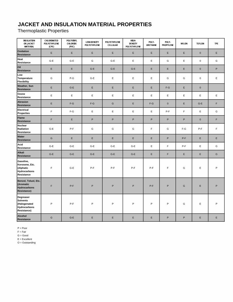
Thermoplastic Properties
INSULATIONOR JACKETMATERIAL
CHLORINATEDPOLYETHYLENE
(CPE)
POLYVINYLCHLORIDE
(PVC)
LOW-DENSITYPOLYETHYLENE
POLYETHYLENE CELLULAR
HIGH-DENSITY
POLYETHYLENE
POLY-URETHANE
POLY-PROPYLENE NYLON TEFLON TPE
OxidationResistance E E E E E E E E 0 E
HeatResistance G-E G-E G G-E E E G E 0 G
OilResistance E E G-E G-E G-E E E E 0 P
LowTemperatureFlexibility
G P-G G-E E E E G G 0 E
Weather, Sun Resistance E G-E E E E E F-G E 0
OzoneResistance E E E E E E E E E E
AbrasionResistance E F-G F-G G E F-G 0 E G-E F
Electrical Properties F F-G E E E E P-F F E G
FlameResistance F E P P P P P P 0 F
NuclearRadiation Resistance
G-E P-F G G G F G F-G P-F F
WaterResistance G E E E E E P P-F E E
AcidResistance G-E G-E G-E G-E G-E E F P-F E G
AlkaliResistance G-E G-E G-E G-E G-E E F E E G
Gasoline, Kerosene, Etc. (Alphatic Hydrocarbons Resistance
F G-E P-F P-F P-F P-F F G E P
Benzol, Toluol, Etc. (Aromatic Hydrocarbons Resistance)
F P-F P P P P-F P G E P
DegreaserSolvents (Halogenated Hydrocarbons Resistance)
P P-F P P P P P G E P
AlcoholResistance G G-E E E E E P P E E
P = PoorF = FairG = GoodE = ExcellentO = Outstanding
JACKET AND INSULATION MATERIAL PROPERTIES
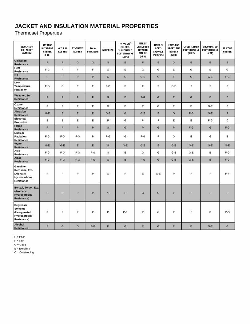
Thermoset Properties
INSULATIONOR JACKETMATERIAL
STYRENEBUTADIENE
RUBBER(SBR)
NATURALRUBBER
SYNTHETICRUBBER
POLY-BUTADIENE NEOPRENE
HYPALON®
CHLORO-SULFONATED
POLYETHYLENE(CSPE)
NITRILEOR RUBBERBUTADINE
NITRILE(NBR)
NITRILE/POLY-
CHLORIDE(NBR/PVC)
ETHYLENEPROPYLENE
RUBBER(EPR)
CROSS-LINKEDPOLYETHYLENE
(XLPE)
CHLORINATEDPOLYETHYLENE
(CPE)
SILICONERUBBER
OxidationResistance F F G G G E F E G E E E
HeatResistance F-G F F F G E G G E G E G
OilResistance P P P P G G G-E G F G G-E F-G
LowTemperatureFlexibility
F-G G E E F-G F F F G-E 0 F 0
Weather, Sun Resistance F F F F G E F-G G E G E 0
OzoneResistance P P P P G E P G E E G-E 0
AbrasionResistance G-E E E E G-E G G-E E G F-G G-E F
Electrical Properties E E E E F G P F E E F-G 0
FlameResistance P P P P G G P G P F-G G F-G
NuclearRadiation Resistance
F-G F-G F-G P F-G G F-G P G E G E
WaterResistance G-E G-E E E G G-E G-E E G-E G-E G-E G-E
AcidResistance F-G F-G F-G F-G G E G G G-E G-E E F-G
AlkaliResistance F-G F-G F-G F-G G E F-G G G-E G-E E F-G
Gasoline, Kerosene, Etc. (Alphatic Hydrocarbons Resistance
P P P P G F E G-E P F F P-F
Benzol, Toluol, Etc. (Aromatic Hydrocarbons Resistance)
P P P P P-F F G G F F F P
DegreaserSolvents (Halogenated Hydrocarbons Resistance)
P P P P P P-F P G P F P P-G
AlcoholResistance F G G F-G F G E G P E G-E G
P = PoorF = FairG = GoodE = ExcellentO = Outstanding
JACKET AND INSULATION MATERIAL PROPERTIES

XLP CROSSLINKED POLYETHYLENE INSULATIONS(LOW VOLTAGE)
Physical and Electrical Specification Data
GuaranteedValue
TypicalValue
GuaranteedValue
TypicalValue
PHYSICAL PROPERTIES
Original Tensile Strength, psi 1800 min. 2300 1800 min. 2100
Original Elongation, percent 250 min, 425 250 min. 400
Aged - Air Oven - 168 Hr. @ 121°C
Percent of Original
Tensile 75 min. 100 75 min. 95
Elongation 75 min. 95 75 min. 85
Hot Creep, 150°C
Elongation, % 100 max. 40 100 max. 15Set, % 5 max. 0 5 max. 0
ELECTRICAL PROPERTIES
Insulation Resistance Constant (K) 10,000 min. 75,000 10,000 min. 50,000
SIC at 75°C 6.0 max. 3.1 6.0 max. 3.45
Accelerated Water Absorption
% Change in SIC, 75°C Water
1 - 14 days 3.0 max. 1.6 3.0 max. 2.6
7 - 14 days 1.5 max. 0.6 1.5 max. 0.9
Stability Factor after 14 Days 1.0 max. 0.1 1.0 max. 0.3
COLD BEND
1 Hr. @ 3 X O.D. -30°C < - 40°C - 30°C < - 40°C
FLAME RESISTANCE
Complies with:ICEA S-95-658 / NEMA WC70
Class X-2 Class X-2
Test Requirements
0-2000 Volts 0-2000 Volts FR-XLP
UL Horizontal, Passes UL VW-1 Vertical, Passes

EPR INSULATIONS
Physical and Electrical Specification Data
GuaranteedValue
TypicalValue
GuaranteedValue
TypicalValue
PHYSICAL PROPERTIESOriginal Tensile Strength, psi 700 min. 1000 1200 min. 1800Original Elongation, percent 250 min. 400 250 min. 370Tensile Stress @ 100% Elong., psi N/A N/A 500 min. 750Aged - Air Oven - 168 Hr. @ 121°C
Percent of OriginalTensile 75 min. 95 80 min. 95Elongation 75 min, 90 80 min, 95
Hot Creep, 150°CElongation, % 50 max. 10 50 max. 10Set, % 5 max. 0 5 max. 0
ELECTRICAL PROPERTIES
Insulation Resistance Constant (K) 20,000 min. >100,000 20,000 min. > 100,000SIC at R.T. 4.0 max. 2.8 4.0 max. 2.7D.F. at R.T., % 2.0 max. 1.0 1.5 max. < 0.5
Accelerated Water AbsorptionSIC, 75°C Water 4.0 max. 2.8 4.0 max. 2.7% Change in SIC, 75°C Water
1 - 14 days 3.5 max. < 0.5 3.5 max. < 0.57 - 14 days 1.5 max. < 0.5 1.5 max, < 0.5
Stability Factor after 14 Days 1.0 max. .10 1.0 max. .10
COLD BEND
1 Hr. @ 3 X O.D. - 35°C < - 40°C - 35°C < - 40°C
Complies with:
ICEA S-95-658 / NEMA WC 70ICEA S-96-659 / NEMA WC 71ICEA S-93-639 / NEMA WC 74ICEAS-97-682ICEA S-94-649ICEA S-75-381 / NEMA WC 58
Class E-1 Class E-1 and E-2Class E-1 Class E-1 and E-2
Test Requirements
0-5000 Volts 0-35,000 Volts
Class I Class I and IIType I Type I and II
Class I Class I and IIClass I Class I and II

FLAME-RETARDANT PVC JACKET
Specification Data
Test Requirements Guaranteed Typical
PHYSICAL PROPERTIES
Original Tensile Strength, psi 1500 min. 2400
Original Elongation, percent 100 min. 300
Aged - Air Oven - 120 Hr. @ 100°C
Percent of Original
Tensile 85 min. 90
Elongation 60 min. 85
Oil Immersion - 4 Hr. @ 70°C
IRM 902 Oil
Percent of Original
Tensile 80 min. 90
Elongation 60 min. 90
Heat Distortion @ 121°C
Percent 50 max. 20
Heat Shock @ 121 OC No Cracks No Cracks
Cold Bend
1 Hr. @ 8 X O.D. - 35°C < - 40°C
WEATHEROMETER
720 Hour
Percent of Original
Tensile 80 min. 95
Elongation 80 min. 95
OXYGEN INDEX 28 min. 29
Complies with:
ICEA S-95-658 / NEMA WC 70ICEA S-96-659 / NEMA WC 71ICEA S-93-639 / NEMA WC 74ICEA S-97-682ICEA S-94-649ICEA S-73-532 / NEMA WC 57ICEA S-75-381 / NEMA WC 58
Information on this sheet subject to change without notice
Table 7-6Table 7-6Table 4-2Table 4-7
Table 4-1Table 5-1Table 7-1
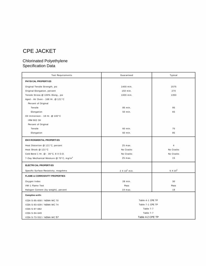
CPE JACKET
Chlorinated PolyethyleneSpecification Data
Test Requirements Guaranteed Typical
PHYSICAL PROPERTIES
Original Tensile Strength, psi 1400 min. 1575
Original Elongation, percent 150 min. 270
Tensile Stress @ 100% Elong., psi 1000 min. 1350
Aged - Air Oven - 168 Hr. @ 121°C
Percent of Original
Tensile 85 min. 95
Elongation 50 min. 65
Oil Immersion - 18 Hr. @ 100°C
IRM 902 Oil
Percent of Original
Tensile 60 min. 75
Elongation 60 min. 85
ENVIRONMENTAL PROPERTIES
Heat Distortion @ 121°C, percent 25 max. 4
Heat Shock @ 121°C No Cracks No Cracks
Cold Bend 1 Hr. @ - 35°C, 8 X O.D. No Cracks No Cracks
7-Day Mechanical Moisture @ 70°C, mg/in2 25 max. 15
ELECTRICAL PROPERTIES
Specific Surface Resistivity, megohms 2 X 10⁵ min. 5 X 10⁶
FLAME & CORROSIVITY PROPERTIES
Oxygen Index 28 min. 30
VW-1 Flame Test Pass Pass
Halogen Content (by weight), percent 19 max. 18
Complies with:
ICEA S-95-658 / NEMA WC 70
ICEA S-93-639 / NEMA WC 74
ICEA S-97-682
ICEA S-94-649
ICEA S-73-532 / NEMA WC 57
Table 7-7
Table 4-2 CPE TP
Table 4-1 CPE TP
Table 7-1 CPE TP
Table 7-7

BENDING RADII AND PULLING TENSIONS
MINIMUM BENDING RADII
Power Cables 600 Volts. without Sheath. Shielding or Armor
The minimum bending radii for single and multi-conductor cables rated 600 volts and less, and without lead sheath, shielding or armor;
Thickness of Conductor
Minimum Bending Radius as a Multiple of Cable Diameter
Insulation Overall Diameter of Cable in Inches in Mils
1.000 and Less
1.001 to 2.000
2.001 and Over
169 and less
170 - 310
311 and over
4
5
-
5
6
7
6
7
8
Power Cables Over 600 Volts. without Sheath. Shielding or Armor
1. The minimum bending radius for all cables is eight times the overall cable diameter.
Shielded Cables without Armor. All Voltages
1. The minimum bending radius for single conductor cable and multi-conductor cable with an overall shield is twelve times the overall cable diameter.
2. The minimum bending radius for multi-conductor or multiplexed cables having individually shielded conductors is twelve times the diameter of one of the individual conductors or seven times the overall diameter, whichever is greater.
3. The minimum bending radius for lead sheathed cables is twelve times the overall cable diameter.
Interlocked Armored Cable. All Voltages
1. The minimum bending radius for cables with non-shielded conductors is seven times the armor 0.0..
2. The minimum bending radius for cables with shielded conductors is twelve times the diameter of one phase conductor or seven times the overall diameter, whichever is greater.
Note: The minimum bending radius applies to the inner surface of the cable and not to the cable axis.
PULLING TENSIONS
A. Maximum Pulling Tension on Cable
(1) With pulling eye attached to copper conductors, the maximum pulling tension in pounds should not exceed 0.008 times cir-mil area.
(2) With pulling eye attached to aluminum conductors, the maximum pulling tension in pounds should not exceed 0.006 times cir-mil area.
TM =0.008 x n x CM where
TM =max. tension, lb.
n = number of conductors
CM = cir-mil area of each copper conductor
(3) With cable grip over lead sheath, the maximum pulling tension in pounds should not exceed 1500 Ib.l sq. inch of lead sheath cross-sectional area for commercial lead
TM =4712 t (0 - t) where
t =sheath thickness, inches
0= overall diameter of cable, inches
(4) With cable grip over non-leaded cable, the maximum pulling tension should not exceed 1000 lb. and may not exceed the maximum tension based on 0.008 or 0.006 x total conductor area.
(5) When more than three conductors are pulled together, the maximum pulling tension should be reduced 20%.
B. Maximum Permissible PUlling Length TMLM-fW
where L M =pulling length, feet (straight section)
TM = maximum tension, lb.
W = weight of cable per foot, lb.
f = coefficient of friction (usually 0.5)
C. Pulling Tension Requirements in Ducts or Conduits:
(1) For straight sections, the pulling tension in pounds equals the length of duct or conduit multiplied by the weight per foot of cable and the coefficient of friction (paragraph B, above). T=LWf
(2) For curved sections, the following formula applies:
=T faTc 1 e where
T = tension exiting curved section, lb. c
T1 = tension entering curved section, lb.
a = angle of bend in radians (1 radian = 57.3 deg.)
f = coefficient of friction (usually 0.5)
e = naperian logarithm base
(3) To limit the sidewall bearing pressure on cables at bends, the maximum pulling tension in pounds shall not exceed the following factor times the radius of curvature of bend expressed in feet:
Cable Type Factor
Low Voltage 16-10 AWG Low Voltage 8 AWG & LGR 5kV NonShielded 5kV-35kV Interlocked Armor (all voltages)
300 500 500 500 300
Administrator
Line
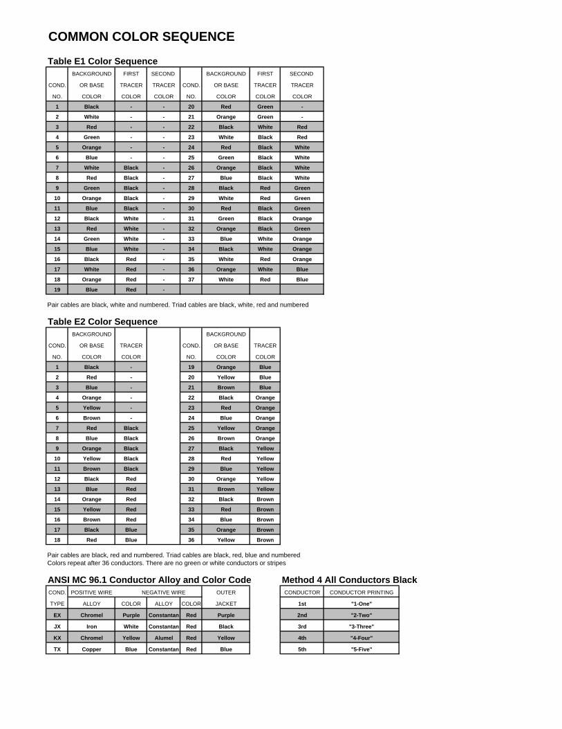
Table E1 Color SequenceBACKGROUND FIRST SECOND BACKGROUND FIRST SECOND
COND. OR BASE TRACER TRACER COND. OR BASE TRACER TRACER
NO. COLOR COLOR COLOR NO. COLOR COLOR COLOR
1 Black - - 20 Red Green -
2 White - - 21 Orange Green -
3 Red - - 22 Black White Red
4 Green - - 23 White Black Red
5 Orange - - 24 Red Black White
6 Blue - - 25 Green Black White
7 White Black - 26 Orange Black White
8 Red Black - 27 Blue Black White
9 Green Black - 28 Black Red Green
10 Orange Black - 29 White Red Green
11 Blue Black - 30 Red Black Green
12 Black White - 31 Green Black Orange
13 Red White - 32 Orange Black Green
14 Green White - 33 Blue White Orange
15 Blue White - 34 Black White Orange
16 Black Red - 35 White Red Orange
17 White Red - 36 Orange White Blue
18 Orange Red - 37 White Red Blue
19 Blue Red -
Pair cables are black, white and numbered. Triad cables are black, white, red and numbered
Table E2 Color SequenceBACKGROUND BACKGROUND
COND. OR BASE TRACER COND. OR BASE TRACER
NO. COLOR COLOR NO. COLOR COLOR
1 Black - 19 Orange Blue
2 Red - 20 Yellow Blue
3 Blue - 21 Brown Blue
4 Orange - 22 Black Orange
5 Yellow - 23 Red Orange
6 Brown - 24 Blue Orange
7 Red Black 25 Yellow Orange
8 Blue Black 26 Brown Orange
9 Orange Black 27 Black Yellow
10 Yellow Black 28 Red Yellow
11 Brown Black 29 Blue Yellow
12 Black Red 30 Orange Yellow
13 Blue Red 31 Brown Yellow
14 Orange Red 32 Black Brown
15 Yellow Red 33 Red Brown
16 Brown Red 34 Blue Brown
17 Black Blue 35 Orange Brown
18 Red Blue 36 Yellow Brown
Pair cables are black, red and numbered. Triad cables are black, red, blue and numbered.Colors repeat after 36 conductors. There are no green or white conductors or stripes
ANSI MC 96.1 Conductor Alloy and Color Code Method 4 All Conductors BlackCOND. POSITIVE WIRE NEGATIVE WIRE OUTER CONDUCTOR CONDUCTOR PRINTING
TYPE ALLOY COLOR ALLOY COLOR JACKET 1st "1-One"
EX Chromel Purple Constantan Red Purple 2nd "2-Two"
JX Iron White Constantan Red Black 3rd "3-Three"
KX Chromel Yellow Alumel Red Yellow 4th "4-Four"
TX Copper Blue Constantan Red Blue 5th "5-Five"
COMMON COLOR SEQUENCE


