American Power Design, Inc.
8
Rev. 3.01 31-JAN-2014 "The best high voltage design solution" American Power Design, Inc. C50 SERIES 50 WATT DC/DC CONVERTERS Tel (888) 894-4446 WWW.APOWERDESIGN.COM Fax (603) 898-6534 Page 1 of 8 FEATURES The C50 Series of DC/DC converters offers a single output to 28Vdc and 500Vdc of isolation. They are available in either PC or Chassis mount configurations. Their rugged enclosure, low output ripple, and excellent regulation characteristics make them ideally suited for harsh environment applications that demand a high degree of performance. All models will tolerate a short circuit indefinitely. Voltage Accuracy .......................................................... +/- 1% Line Regulation .......................................................... +/- 0.1% Load Regulation ......................................................... +/- 0.1% Output Ripple ......................................................< 100mV P-P Output Trim .................................................................. +/-10% Temp. Stability ................................................... +/-0.02%/°C Temp. (Operating , Case) ................................... -40 to +85°C Temp. (Storage) ............................................... -40 to +125°C Case Material ........................................... Black Coated Metal (With Non-Conductive Base Plate) Input Filter .............................................................. PI Network Efficiency ............................................................... 85% (typ.) Short Circuit Protection ........................................ Continuous Switching Frequency ................................................. 130 kHz Output Isolation .......................................................... 500 Vdc Input / Output Capacitance ....................................... < 1300pF ELECTRICAL SPECIFICATIONS GENERAL SPECIFICATIONS 4 Customer Selects Output Voltage 4 Outputs to 28 Vdc 4 Wide Input Ranges (10-20Vdc, 18-36Vdc, 20-60Vdc, 36-72Vdc) 4 Excellent Line & Load Regulation 4 500 Vdc Output Isolation 4 Continuous Short Circuit Protection 4 Thermal Shutdown (Self-Resetting) 4 Available in Chassis Mount Logic Shutdown .................................................... Logic 0 (off) EMI/RFI ......................................................... Six Sided Shield Derating ......................................................................... None Cooling ............................... Free-Air Convection or Forced Air Thermal Shut Down ......................................... 100°C/+/- 5°C (Self-Resetting) PHYSICAL SPECIFICATIONS Dimensions ......................................... 2.75 x 4.8 x 0.92 inches Weight ........................................................................ 13.5 Oz NOT RECOMMENDED FOR NEW DESIGNS
Transcript of American Power Design, Inc.

Rev. 3.01 31-JAN-2014
"The best high voltage design solution"
American Power Design, Inc.
C50 SERIES 50 WATT DC/DC CONVERTERS
Tel (888) 894-4446 WWW.APOWERDESIGN.COM Fax (603) 898-6534
Page 1 of 8
FEATURES
The C50 Series of DC/DC converters offers a single output to 28Vdc and 500Vdc of isolation. They are available in either PC or Chassis mount configurations. Their rugged enclosure, low output ripple, and excellent regulation characteristics make them ideally suited for harsh environment applications that demand a high degree of performance. All models will tolerate a short circuit indefinitely.
Voltage Accuracy .......................................................... +/- 1%
Line Regulation .......................................................... +/- 0.1%
Load Regulation ......................................................... +/- 0.1%
Output Ripple ......................................................< 100mV P-P
Output Trim .................................................................. +/-10%
Temp. Stability ................................................... +/-0.02%/°C
Temp. (Operating , Case) ................................... -40 to +85°C
Temp. (Storage) ............................................... -40 to +125°C
Case Material ........................................... Black Coated Metal (With Non-Conductive Base Plate)
Input Filter .............................................................. PI Network
Efficiency ............................................................... 85% (typ.)
Short Circuit Protection ........................................ Continuous
Switching Frequency ................................................. 130 kHz
Output Isolation .......................................................... 500 Vdc
Input / Output Capacitance ....................................... < 1300pF
ELECTRICAL SPECIFICATIONS
GENERAL SPECIFICATIONS
4 Customer Selects Output Voltage 4 Outputs to 28 Vdc4 Wide Input Ranges (10-20Vdc, 18-36Vdc, 20-60Vdc, 36-72Vdc)
4 Excellent Line & Load Regulation4 500 Vdc Output Isolation4 Continuous Short Circuit Protection4 Thermal Shutdown (Self-Resetting)
4 Available in Chassis Mount
Logic Shutdown .................................................... Logic 0 (off)
EMI/RFI ......................................................... Six Sided Shield
Derating ......................................................................... None
Cooling ............................... Free-Air Convection or Forced Air
Thermal Shut Down ......................................... 100°C/+/- 5°C (Self-Resetting)
PHYSICAL SPECIFICATIONS
Dimensions ......................................... 2.75 x 4.8 x 0.92 inches
Weight ........................................................................ 13.5 Oz
NOT R
ECOM
MEN
DED
FOR N
EW D
ESIGNS

Rev. 3.01 31-JAN-2014
"The best high voltage design solution"
American Power Design, Inc.
C50 SERIES 50 WATT DC/DC CONVERTERS
Tel (888) 894-4446 WWW.APOWERDESIGN.COM Fax (603) 898-6534
Page 2 of 8
C50-12/A/Y/Y ComplianceRoHs
Product Family
Total Output Power
REPRESENTATIVE MODEL LISTING
OUTPUTSPECIFICATIONS
MODEL NUMBER / INPUT RANGE
10-20VDC 18-36VDC 20-60VDC 36-72VDC
VOLTAGE CURRENT Non-RoHs RoHs Non-RoHs RoHs Non-RoHs RoHs Non-RoHs RoHs
3.3 Vdc 15 A C50-3.3 C50-3.3/Y C50-3.3/A C50-3.3/A/Y C50-3.3/B C50-3.3/B/Y C50-3.3/C C50-3.3/C/Y
5 Vdc 10 A C50-5 C50-5/Y C50-5/A C50-5/A/Y C50-5/B C50-5/B/Y C50-5/C C50-5/C/Y
6 Vdc 8.3 A C50-6 C50-6/Y C50-6/A C50-6/A/Y C50-6/B C50-6/B/Y C50-6/C C50-6/C/Y
9 Vdc 5.5 A C50-9 C50-9/Y C50-9/A C50-9/A/Y C50-9/B C50-9/B/Y C50-9/C C50-9/C/Y
12 Vdc 4.2 A C50-12 C50-12/Y C50-12/A C50-12/A/Y C50-12/B C50-12/B/Y C50-12/C C50-12/C/Y
15 Vdc 3.3 A C50-15 C50-15/Y C50-15/A C50-15/A/Y C50-15/B C50-15/B/Y C50-15/C C50-15/C/Y
18 Vdc 2.8 A C50-18 C50-18/Y C50-18/A C50-18/A/Y C50-18/B C50-18/B/Y C50-18/C C50-18/C/Y
21 Vdc 2.4 A C50-21 C50-21/Y C50-21/A C50-21/A/Y C50-21/B C50-21/B/Y C50-21/C C50-21/C/Y
24 Vdc 2.1 A C50-24 C50-24/Y C50-24/A C50-24/A/Y C50-24/B C50-24/B/Y C50-24/C C50-24/C/Y
28 Vdc 1.8 A C50-28 C50-28/Y C50-28/A C50-28/A/Y C50-28/B C50-28/B/Y C50-28/C C50-28/C/Y
Alternate Input Range/A 18Vdc - 36Vdc/B 20Vdc - 60Vdc/C 36Vdc - 72Vdc
Customer Selects Output Voltage
The C50 Series are designed such that the customer may order any output voltage from 3.3Vdc to 28Vdc at no additional charge.
NOT R
ECOM
MEN
DED
FOR N
EW D
ESIGNS

Rev. 3.01 31-JAN-2014
"The best high voltage design solution"
American Power Design, Inc.
C50 SERIES 50 WATT DC/DC CONVERTERS
Tel (888) 894-4446 WWW.APOWERDESIGN.COM Fax (603) 898-6534
Page 3 of 8
Dimensions are in Inches[Metric equivalents in brackets]
STANDARD PC MOUNT
4.820 [122.43]
4 p
lc. 0.3
75"
[9.5
25]
3 p
lc. 0.3
75"
[9.5
25]
3.600 [91.44]
#4-40 Threaded Through Inserts (4 places)
NONCONDUCTIVE BASE PLATEMIN PIN LENGTH
BLACK ANODIZED ALUMINUM CASE
2.770 [70.36]0.200 [5.08]
Option D Heat Sink (-HSD)
Option E Heat Sink (-HSE)
2.2
50 [57.1
5]
2.7
70 [70.3
6]
0.260 [6.60]
0.635 [16.13]
0.610 [15.49]
PINS - 0.040 [1.02] Dia.
TIN PLATED BRASS, MATTE FINISH
0.890 [22.61]
2
3
4
5 10
9
8
7
6
AMERICAN POWER DESIGNwww.apowerdesign.com
Option D Heat Sink (-HSD)
Option E Heat Sink (-HSE)
PIN # FUNCTION PIN # FUNCTION
1 No Pin 6 -V Out
2 - Input 7 + V Out
3 + Input 8 - Sense
4 On / Off 9 Trim
5 Case 10 + Sense
0.90 [22.86]
0.47 [11.94]
( BOTTOM VIEW)
NOT R
ECOM
MEN
DED
FOR N
EW D
ESIGNS
Rev. 3.01 31-JAN-2014
"The best high voltage design solution"
American Power Design, Inc.
C50 SERIES 50 WATT DC/DC CONVERTERS
Tel (888) 894-4446 WWW.APOWERDESIGN.COM Fax (603) 898-6534
Page 4 of 8
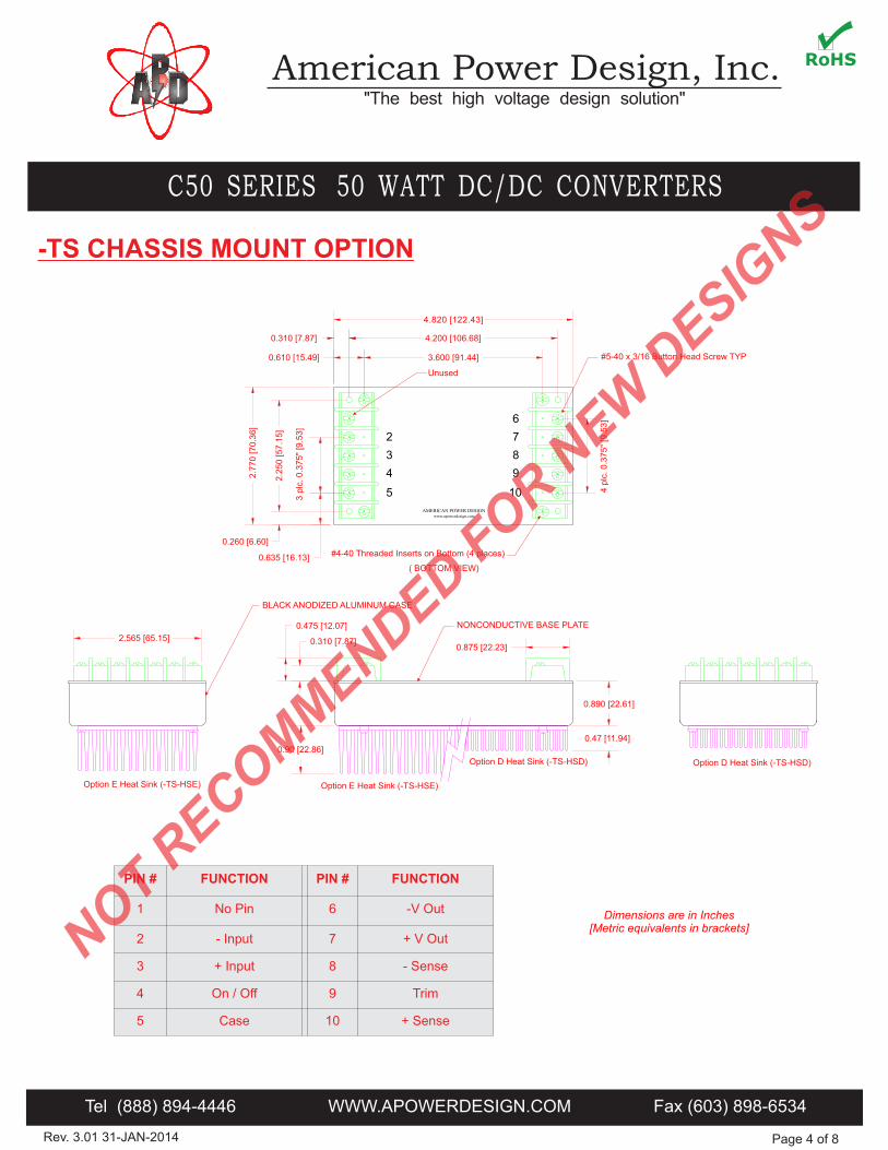
-TS CHASSIS MOUNT OPTION
AMERICAN POWER DESIGNwww.apowerdesign.com
2
3
4
5 10
9
8
7
6
3 p
lc. 0.3
75"
[9.5
3]
3.600 [91.44]
2.565 [65.15] 0.310 [7.87]
0.475 [12.07]
0.875 [22.23]
BLACK ANODIZED ALUMINUM CASE
4.200 [106.68]
2.2
50 [57.1
5]
4.820 [122.43]
Option D Heat Sink (-TS-HSD)
2.7
70 [70.3
6]
0.260 [6.60]
0.635 [16.13]
0.310 [7.87]
0.610 [15.49]
Unused
#5-40 x 3/16 Button Head Screw TYP
#4-40 Threaded Inserts on Bottom (4 places)
4 p
lc. 0.3
75"
[9.5
3]
Option E Heat Sink (-TS-HSE)
0.890 [22.61]
Dimensions are in Inches[Metric equivalents in brackets]
PIN # FUNCTION PIN # FUNCTION
1 No Pin 6 -V Out
2 - Input 7 + V Out
3 + Input 8 - Sense
4 On / Off 9 Trim
5 Case 10 + Sense
Option D Heat Sink (-TS-HSD)
Option E Heat Sink (-TS-HSE)
0.47 [11.94]
0.90 [22.86]
NONCONDUCTIVE BASE PLATE
( BOTTOM VIEW)
NOT R
ECOM
MEN
DED
FOR N
EW D
ESIGNS

Rev. 3.01 31-JAN-2014
"The best high voltage design solution"
American Power Design, Inc.
C50 SERIES 50 WATT DC/DC CONVERTERS
Tel (888) 894-4446 WWW.APOWERDESIGN.COM Fax (603) 898-6534
Page 5 of 8
APPLICATION NOTES
INPUT AND OUTPUT IMPEDANCE
The C50 Series of power converters have been designed to be stable with no external capacitors when used in low inductance input and output circuits. However, in some applications, the inductance associated with the distribution from the power source to the input of the converter can affect the stability of the converter. The addition of a 100 µF electrolytic capacitor with an ESR <1 Ohm across the input helps ensure stability of the converter. In many applications, the user has to use decoupling capacitance at the load.
SHORT CIRCUIT PROTECTION
The C50 Series is equipped with short circuit protection. The converter will fold-back the input power whenever a short circuit is applied to its output and automatically recover after the overload condition is removed.
If remote sensing is not required, the SENSE(-) (Pin 8) must be connected to the Output(-) (Pin 6), and the SENSE(+) (Pin 10) must be connected to the Output(+) (Pin 7) to ensure the converter will regulate at the specified output voltage. If these connections are not made, the converter will deliver an output voltage that is slightly higher than the specified value.
ISOLATION
The output of the C50 Series is galvanically isolated from both the input and case, capacitance is < 1300pF and resistance is > 10G Ohm. The figure below shows the internal RC network that connects the Case (Pin 5) to Input(-) (Pin 2). This aides in reducing unwanted noise.
- Input
+ Input
On / Off
Case + Sense
Trim
- Sense
+ Output
- Output
AMERICAN POWER DESIGNwww.apowerdesign.com
0.0
1uF
1M
Ohm
INRUSH CURRENT
The inrush current of the C50 Series has been kept as low as possible. However, a series resistor may be inserted in the input line to limit this current further.
+ Sense
Trim
- Sense
+ Output
- Output
Load
REMOTE SENSING
The C50 Series is equipped with remote sensing, this feature compensates for voltage drops occurring between the output pins of the converter and the load. The SENSE(-) (Pin 8) and SENSE(+) (Pin 10) should be connected at the load or at the point where regulation is required.
The feedback through the sensing pins allows the converter to output a higher voltage at the output pins to compensate for the voltage drop on the connections between the converters output and the load. It will compensate for up to 0.5V drop between the converter and the load.
Because the sense leads carry minimal current, large traces on the end-user board are not required. However, sense traces should be located close to a ground plane to minimize system noise and insure optimum performance. When wiring discretely, twisted pair wires should be used to connect the sense lines to the load to reduce susceptibility to noise.
The figure below shows the correct method of installation using this option.
NOTE: Always disconnect the sense wires before disconnecting the output wires when the unit is under power. otherwise, the supply may be permanently damaged
NOT R
ECOM
MEN
DED
FOR N
EW D
ESIGNS

Rev. 3.01 31-JAN-2014
"The best high voltage design solution"
American Power Design, Inc.
C50 SERIES 50 WATT DC/DC CONVERTERS
Tel (888) 894-4446 WWW.APOWERDESIGN.COM Fax (603) 898-6534
Page 6 of 8
APPLICATION NOTES
Re
lay
Co
nta
cts
-V
c REMOTE ON/OFF CONTROL
The On/Off control (Pin 4) allows the user to shut down the converter mechanically or logically using a relay or a TTL or CMOS logic signal.
- Input
+ Input
On / Off
Case
- Input
+ Input
On / Off
Case
+
+ Sense
Trim
- Sense
+ Output
- OutputTo Load
The figure below shows how to adjust the output voltage using an external Trim Pot.
NOTE: Current sharing can be adjusted by trimming both converters to the same output voltage
50K 1/4W Trim Pot
TRIM OUTPUT
The C50 Series is equipped with an output trim pin (Pin 9), this feature allows the user to adjust the output voltage up or down 10% using a fixed precision resistor or adjustable trim pot.
The figure below shows how to adjust the output voltage using a fixed precision resistor.
+ Sense
Trim
- Sense
+ Output
- OutputTo Load
NOTE: Proper utilization of Remote Sensing is needed to achieve a stable output voltage
Trim Down
Trim Up
*10K 1/4W for <12V Output
CONNECTION IN SERIES
Figure below shows how to connect multiple outputs in series with the use of shunt diodes, taking into consideration that the highest achieved output voltage should remain below the rated isolation voltage.
UNIT 2
- Input
+ Input
On / Off
Case + Sense
Trim
- Sense
+ Output
- Output
AMERICAN POWER DESIGNwww.apowerdesign.com
Load
UNIT 1
- Input
+ Input
On / Off
Case + Sense
Trim
- Sense
+ Output
- Output
AMERICAN POWER DESIGNwww.apowerdesign.com
CONNECTION IN PARALLEL
The figure below show how to connect outputs of several units with equal nominal output voltage in parallel with the use of oring diodes.
UNIT 2
- Input
+ Input
On / Off
Case + Sense
Trim
- Sense
+ Output
- Output
AMERICAN POWER DESIGNwww.apowerdesign.com
Load
UNIT 1
- Input
+ Input
On / Off
Case + Sense
Trim
- Sense
+ Output
- Output
AMERICAN POWER DESIGNwww.apowerdesign.com
NOTE: Proper utilizations of Remote Sensing is needed to achieve a stable output voltage
Converter Off: Vc <1.5VdcConverter On: Vc >3Vdc
NOT R
ECOM
MEN
DED
FOR N
EW D
ESIGNS

Rev. 3.01 31-JAN-2014
"The best high voltage design solution"
American Power Design, Inc.
C50 SERIES 50 WATT DC/DC CONVERTERS
Tel (888) 894-4446 WWW.APOWERDESIGN.COM Fax (603) 898-6534
Page 7 of 8
STARTUP TRANSIENT
Figure below shows a typical output voltage during turn-on, measured at no load current with no additional output filtering.
Figure below shows a typical output voltage during turn-on, measured at full rated load current with no additional output filtering.
LOAD TRANSIENT
Figure below shows a typical output voltage response, measured during a transition from full rated load current to no load current with no additional output filtering.
Figure below shows a typical output voltage response, measured during a transition from no load current to full rated load current with no additional output filtering.
APPLICATION NOTES
NOT R
ECOM
MEN
DED
FOR N
EW D
ESIGNS

Rev. 3.01 31-JAN-2014
"The best high voltage design solution"
American Power Design, Inc.
C50 SERIES 50 WATT DC/DC CONVERTERS
Tel (888) 894-4446 WWW.APOWERDESIGN.COM Fax (603) 898-6534
Page 8 of 8
APPLICATION NOTES
CLEANING AGENTS
In order to avoid possible damage, any penetration ofcleaning fluids must be prevented, since the powersupplies are not hermetically sealed.
TECHNICAL REVISIONS
The appearance of products, including safety agency certifications pictured on labels, may change dependingon the date manufactured. Specifications are subject to change without notice.
NUCLEAR AND MEDICAL APPLICATIONS
American Power Design products are not designed, intended for use in, or authorized for use as critical components in life support systems, equipment used in hazardous environments, or nuclear control systems without the express written consent of American Power Design, Inc.
WARRANTY
All products manufactured by American Power Design, Inc. (APD) are warranted to be free of defects due to material or workmanship for a period of one year from date of shipment. At our option, APD will repair or replace any non-conforming product.APD expressly disclaims any liability for consequential or incidental damages resulting from the use or misuse of its products by the purchaser or others.This warranty is in lieu of all warranties expressed or implied, including the warranties of merchantability. No other warranties, obligations, or liabilities are expressed or implied.All products being returned for repair require a return material authorization(RMA) assigned by APD prior to return shipment.
SAFETY REQUIREMENTS
The converters are designed to meet North American and International safety regulatory requirements per UL 60950-1/CSA 22.2 No. 60950-1-07 Second Edition, IEC 60950-1: 2005, and EN 60950-1:2006. Basic Insulation is provided between input and output. To comply with safety agencies requirements, an input line fuse must be used external to the converter. The table below provides the recommended fuse rating for use with this family of products.
If one input fuse is used for a group of modules, the maximum fuse rating should not exceed 20A.
Input Voltage Range Fuse Rating
10-20Vdc 10A
18-36Vdc 6A
20-60Vdc 4A
36-72Vdc 2.5A
RIPPLE AND NOISE
Figure below shows a typical output voltage ripple waveform, measured with 20MHz bandwidth filter at full rated load current with no additional output filtering. External low ESR capacitors may be added across output to further reduce ripple.
NOT R
ECOM
MEN
DED
FOR N
EW D
ESIGNS