American Plating Site Remedial Action Construction Report
37
Earth Science + Technology American Plating Site Remedial Action Construction Report 2110 East D Street Tacoma, Washington for Foss Waterway Development Authority May 14, 2013
Transcript of American Plating Site Remedial Action Construction Report

Earth Science + Technology
American Plating Site Remedial Action Construction Report
2110 East D Street Tacoma, Washington
for Foss Waterway Development Authority
May 14, 2013

American Plating Site
Remedial Action Construction Report
2110 East D Street
Tacoma, Washington
for
Foss Waterway Development Authority
May 14, 2013
1101 South Fawcett Avenue, Suite 200
Tacoma, Washington 98402
253.383.4940

American Plating Site
Remedial Action Construction Report
2110 East D Street
Tacoma, Washington
File No. 10751-002-01
May 14, 2013
Prepared for:
Foss Waterway Development Authority
535 E Dock Street, Suite 204
Tacoma, Washington 98402-4630
Attention: Su Dowie
Prepared by:
GeoEngineers, Inc.
1101 South Fawcett Avenue, Suite 200
Tacoma, Washington 98402
253.383.4940
Nick E. Rohrbach
Environmental Scientist
Chris L. Bailey, PE
Environmental Engineer
Iain H. Wingard
Associate
NER:IHW:cn
Disclaimer: Any electronic form, facsimile or hard copy of the original document (email, text, table, and/or figure), if provided, and any attachments are
only a copy of the original document. The original document is stored by GeoEngineers, Inc. and will serve as the official document of record.
Copyright© 2013 by GeoEngineers, Inc. All rights reserved.

May 14, 2013 | Page i File No. 10751-002-01
Table of Contents
1.0 INTRODUCTION .................................................................................................................................... 1
2.0 BACKGROUND ...................................................................................................................................... 1
3.0 REMEDIAL ACTION CONSTRUCTION ACTIVITIES .............................................................................. 3
3.1. Site Preparation ............................................................................................................................ 3
3.1.1. Erosion Control/Stormwater Pollution Prevention .......................................................... 3
3.1.2. Stockpiled Materials Management Areas ........................................................................ 3
3.1.3. Water Management and Disposal .................................................................................... 3
3.2. Demolition ..................................................................................................................................... 4
3.2.1. Utility Protection, Relocation and Restoration ................................................................. 4
3.2.2. Clearing and Grubbing ...................................................................................................... 4
3.2.3. Existing Trash and Debris Collection ................................................................................ 5
3.2.4. Monitoring Well Decommissioning ................................................................................... 5
3.2.5. Removal of Existing Fencing ............................................................................................. 5
3.2.6. Demolition of Asphalt and Concrete Surfaces and Structures ....................................... 5
3.3. Backfill and Capping Material Characterization Sampling ......................................................... 6
3.4. Remedial Excavation and Backfill ................................................................................................ 7
3.4.1. Remedial Excavation and Backfill of REA 1 ..................................................................... 7
3.4.2. Remedial Excavation and Backfill of REA 2 ..................................................................... 9
3.5. Utility Corridor Excavation, Stormwater System Installation, and Backfill ................................. 9
3.5.1. Utility Corridor Area 1 ...................................................................................................... 10
3.5.2. Utility Corridor Area 2 ...................................................................................................... 10
3.5.3. Utility Corridor Area 3 ...................................................................................................... 11
3.6. Material Management, Loading, Transport, and Disposal, or Recycling ................................. 11
3.6.1. REA 1 and UCA 1 ............................................................................................................. 12
3.6.2. REA 2, UCA 2 and UCA 3 ................................................................................................. 12
3.7. Site Grading and Capping ........................................................................................................... 13
3.7.1. Three Foot Cap With Vegetative Surface ....................................................................... 14
3.7.2. Three Foot Cap With Gravel Surface .............................................................................. 14
3.7.3. Eighteen Inch Soil And Asphalt Cap ............................................................................... 14
3.8. Site Restoration .......................................................................................................................... 14
3.8.1. City ROW and Utility Restoration ..................................................................................... 15
3.8.2. Habitat Enhancement Area Plantings ............................................................................ 15
3.8.3. New Groundwater Monitoring Well Installation ............................................................. 15
3.8.4. New Tree Installation ....................................................................................................... 15
3.8.5. Vegetative Surface Area Restoration ............................................................................. 15
3.8.6. Fencing Restoration ........................................................................................................ 15
4.0 CLOSURE ........................................................................................................................................... 16
5.0 REFERENCES .................................................................................................................................... 16
6.0 LIMITATIONS...................................................................................................................................... 16

Page ii | May 14, 2013 | GeoEngineers, Inc. File No. 10751-002-01
LIST OF FIGURES
Figure 1. Vicinity Map
Figure 2. As-Built Drawing
LIST OF TABLES
Table 1. Backfill and Capping Material Characterization Results
Table 2. Excavation Confirmation Sample Results
APPENDICES (INCLUDED ON CD)
Appendix A. American Plating Site Engineering Design Report
Appendix B. Water Characterization Laboratory Analytical Data Reports
Appendic C. Materials Recycling and Disposal Documentation
Appendix D. Well Decommissioning Reports
Appendix E. Backfill and Capping Material Laboratory Analytical Data Reports and Data Quality
Review
Appendix F. Verification Sampling Laboratory Analytical Data Reports and Data Quality Review
Appendix G. Stockpile Sampling Laboratory Analytical Data Reports
Appendix H. Report Limitations and Guidelines for Use

AMERICAN PLATING SITE – REMEDIAL ACTION CONSTRUCTION REPORT Tacoma, Washington
May 14, 2013 | Page 1 File No. 10751-002-01
1.0 INTRODUCTION
This Remedial Action Construction Report (RACR) documents the remedial action construction
activities performed at the American Plating Site (Site) located at 2110 East D Street in Tacoma,
Washington. The American Plating Site occupies approximately 1.4 acres of land that is located
along the eastern shoreline at the head of the Thea Foss Waterway (Figure 1). The remedial action
was conducted by the Foss Waterway Development Authority (FWDA) to satisfy requirements of a
Prospective Purchaser Consent Decree (CD) (No. 03 2 14513 6) issued by the Washington State
Department of Ecology (Ecology) to address contamination resulting from releases from past metal
plating operations at the Site. The American Plating Facility/Site Identification Number (ID) is 1202
and the Cleanup Site ID is 2539. The remedial actions completed at the Site implemented the
preferred cleanup alternative specified in the Ecology-approved Cleanup Action Plan (CAP)
(GeoEngineers, 2003) prepared for the Site. The remedial actions included excavation and
capping of soil with contaminant concentrations greater than the Site cleanup levels.
Remedial action construction activities were performed by Anderson Environmental Construction
(AEC) who was the contractor selected to perform the work. GeoEngineers provided construction
observation and documentation for the FWDA. Construction activities associated with remedial
actions at the Site were performed between April 9, 2012 and December 3, 2012 and included the
following:
■ Site preparation;
■ Demolition;
■ Remedial excavation and backfill;
■ Utility corridor excavation and backfill;
■ Material management, loading, transport and disposal or recycling;
■ Site grading and capping; and
■ Site restoration.
The remedial actions were completed in general accordance with the Ecology-approved
Engineering Design Report (EDR) (GeoEngineers, 2012) prepared for the Site. The EDR prepared
for the American Plating Site is provided in Appendix A. The following sections provide the Site
background and summarize remedial action construction activities.
2.0 BACKGROUND
The American Plating Site was historically used for metal plating activities including zinc, cadmium,
nickel, brass, chromium, and copper plating operations. Former structures included buildings that
housed metal plating operations as well as concrete sumps, drainage features, piping, and tanks
that supported operations performed at the Site (see Figure 2 in Appendix A).
Multiple environmental investigations were conducted at the Site between 1988 and 2003 that
included characterization of soil and groundwater. Additionally, starting in February 2004 and

AMERICAN PLATING SITE – REMEDIAL ACTION CONSTRUCTION REPORT Tacoma, Washington
Page 2 | May 14, 2013 | GeoEngineers, Inc. File No. 10751-002-01
continuing through October 2011, semi-annual groundwater monitoring was performed at the Site.
The results of Site investigations identified the presence of soil and groundwater with metals at
concentrations greater than cleanup levels.
In 2003, interim cleanup actions were performed at the Site. The interim actions included the
following:
■ Characterization, demolition, and disposal of Site buildings;
■ Characterization and disposal of a concrete pad located on the southeast portion of the Site;
■ Characterization and disposal of approximately 18,000 gallons of water contained in an
approximately 25,000 gallon concrete sump;
■ Characterization, demolition, and disposal of the 25,000-gallon concrete sump; and
■ Removal of a UST from the Site with an estimated capacity of 700 gallons.
The Interim Action Cleanup performed in 2003 addressed some, but not all, of the contamination
on the Site.
Remedial actions that remained to be implemented to complete the preferred cleanup alternative
specified in the CAP included the following (see Figure 3 in Appendix A):
■ Decommissioning of groundwater monitoring wells that were present at the Site from previous
investigations;
■ Removal and off-site disposal of soil containing cadmium and chromium above Site cleanup
levels from two Remedial Excavation Areas (REAs) (i.e., REA 1 and REA 2);
■ Construction of utility corridors for installation of stormwater collection, treatment, and
conveyance systems and to provide remediated utility corridors to support future
redevelopment of the Site;
■ Isolation/containment (i.e., capping) of soil on the Site with chemical concentrations greater
than Ecology’s Model Toxics Control Act (MTCA) unrestricted land use soil cleanup levels; and
■ Installation of replacement groundwater monitoring wells.
An EDR was prepared that provides the remedial action plans and specifications and that
describes the requirements for implementing the remaining remedial actions at the Site. The plans
and specifications were used to solicit bids from prospective contractors and to implement the
remaining remedial actions. The EDR specified construction activities to be performed by AEC
which was the selected contractor to implement the remaining remedial actions. The EDR is
provided in Appendix A. The following sections summarize remedial action construction activities.

AMERICAN PLATING SITE – REMEDIAL ACTION CONSTRUCTION REPORT Tacoma, Washington
May 14, 2013 | Page 3 File No. 10751-002-01
3.0 REMEDIAL ACTION CONSTRUCTION ACTIVITIES
3.1. Site Preparation
Site preparation was performed to support completion of the remedial action construction
activities. The following sections summarize Site preparation activities.
3.1.1. Erosion Control/Stormwater Pollution Prevention
Temporary erosion and sediment control (TESC) measures that were installed and maintained
during remedial action construction activities included silt fencing, filter inserts in catch basins,
and sediment traps. The TESC measures were installed prior to initiation of remedial action
construction activities and were maintained in general accordance with the project plans as shown
on plan Sheets C2.0, C2.1, C2.2 and the specifications presented in the EDR (Appendix A).
A protective barrier wall was installed along the western project boundary between April 9th and
11th, 2012. The western project boundary protection barrier wall was installed along the Ordinary
High Water (OHW) line adjacent to the Thea Foss Waterway as shown on Sheet C2.0 and C2.1 of
the project plans to contain all project-generated water, stormwater runoff, and other material (i.e.,
excavated soil, capping material, etc.) within the project boundary. The western project boundary
protection barrier wall was removed on November 28, 2012 after the Site was stabilized in
accordance with project specifications, the Stormwater Pollution Prevention Plan, and the
Restoration Plan shown on Sheet C5.0 of the project plans (Appendix A).
All water generated at the site and stormwater runoff was contained, collected and routed to a
water management system for treatment and testing prior to discharge to the City of Tacoma (City)
sanitary sewer system. No stormwater runoff or project-generated water was discharged from the
Site during the remedial action construction activities. The water that was collected by the water
management system was discharged to the City sanitary sewer system under a Special Approved
Discharge (SAD) Permit. The water was managed, treated, and tested in accordance with the SAD
permit requirements prior to discharge to the sanitary sewer as described in Section 3.1.3 below.
3.1.2. Stockpiled Materials Management Areas
The Stockpiled Materials Management Areas for the excavation of REA 1 and REA 2 were
constructed on April 18, 2012. Other Stockpiled Materials Management Areas were constructed
as needed during remedial action construction activities. The primary Stockpiled Materials
Management Areas were established in the southeastern portion of the Site. The Stockpiled
Materials Management Areas were constructed in general accordance with the project plans as
shown on Sheet C2.1 (Appendix A) and the specifications.
3.1.3. Water Management and Disposal
All stormwater as well as other water generated at the Site during remedial construction activities
was collected and treated prior to discharge to the City sanitary sewer. Water collected at the Site
during remedial action construction activities was initially stored in a 20,000 gallon Baker Tank in
accordance with the City-approved Water Management Plan prepared by AEC. Approval was
received from the City to modify the water treatment system by replacing the one 20,000 gallon

AMERICAN PLATING SITE – REMEDIAL ACTION CONSTRUCTION REPORT Tacoma, Washington
Page 4 | May 14, 2013 | GeoEngineers, Inc. File No. 10751-002-01
Baker Tank with two 3,000 gallon poly tanks. The treatment process consisted of settling of
sediment in the storage tanks followed by physical filtration.
Samples of the treated water (i.e., after settling and filtration) were collected and analyzed in
accordance with the SAD Permit. Water samples were transported to TestAmerica Laboratory in
Fife, Washington for analysis. The water samples were analyzed for the following:
■ pH;
■ Total suspended solids (TSS);
■ Metals;
■ Total and free cyanide;
■ Diesel- and oil-range petroleum hydrocarbons;
■ Gasoline-range petroleum hydrocarbons; and
■ Vinyl chloride.
Chemical analytical data for water characterization samples are included in Appendix B. The
treated water was discharged to the City’s sanitary sewer system after the City’s review of the
analytical data from the water samples and receipt of authorization from the City by AEC. A total of
approximately 5,700 gallons of treated water were discharged to the sanitary sewer system on
June 18, 2012 as part of the remedial action construction activities at the Site.
3.2. Demolition
Demolition activities began on April, 10 2012 and were completed on June 18, 2012. Demolition
generally progressed as pre-capping Site grading was performed. The following sections
summarize Site demolition activities.
3.2.1. Utility Protection, Relocation and Restoration
One utility was re-located along the southern boundary of the Site during remedial activities. A
Qwest/Century-Link (Qwest) communications overhead line located on an existing utility pole was
lifted by Qwest crews to increase the height of the line and provide additional clearance for Berg
Scaffolding (Berg) equipment, materials, and vehicles operating beneath the overhead
communication line.
3.2.2. Clearing and Grubbing
Clearing and grubbing activities were performed to remove brush and existing cottonwood trees
present at the Site. Approximately 15 tons of vegetative material generated during clearing and
grubbing activities was transported to the LRI landfill (LRI) for recycling.
AEC requested approval from the Tacoma-Pierce County Health Department (TPCHD) for disposal
of the cottonwood tree root ball and other Site vegetation in contact with Site soils at LRI. The
specifications included sampling of Site vegetation in contact with Site soil to characterize the
material prior to disposal. The TPCHD approved disposal of Site vegetation in contact with Site soil
at LRI without characterization sampling. The vegetative material in contact with Site soil was

AMERICAN PLATING SITE – REMEDIAL ACTION CONSTRUCTION REPORT Tacoma, Washington
May 14, 2013 | Page 5 File No. 10751-002-01
transported to LRI for disposal with other material excavated from the Site that designated as solid
waste.
Disposal documentation for material resulting from clearing and grubbing activities is provided in
Appendix C.
3.2.3. Existing Trash and Debris Collection
Trash and debris present at the Site was collected and segregated from other Site materials for
disposal. Approximately 11 tons of trash and debris were disposed of at the LRI Landfill in
Graham, Washington that included, but was not limited to, paper, wood, and remnant asphalt.
Additionally, approximately 4 tons of metal debris was transported off site to Cal Steel, LLC in
Tacoma, Washington for recycling. Documentation for disposal and recycling of existing trash and
debris material is provided in Appendix C.
3.2.4. Monitoring Well Decommissioning
Cascade Drilling was subcontracted by AEC to perform monitoring well decommissioning activities.
Cascade Drilling decommissioned monitoring wells MW-1, -2, -3, -4, -5, -7, -9 and -10 on
April 10, 2012 in accordance with the project specifications. AEC attempted to locate monitoring
well MW-12 by performing clearing and grubbing and potholing with an excavator as required in the
project specifications on the northwest portion of the Site in the anticipated area of MW-12 as
identified on Sheet C2.0 (Appendix A). However, monitoring well MW-12 was not located during
remedial action construction activities.
An additional monitoring well was discovered near the northeast corner of the Site on
April 11, 2012. The monitoring well was identified as MW-11. Cascade Drilling returned to the Site
on May 4, 2012 to decommission monitoring well MW-11. However, an obstruction was present
within MW-11 at approximately 10 feet below ground surface (bgs). Due to the presence of the
obstruction, over-drilling was required to decommission the well. Cascade Drilling decommissioned
monitoring well MW-11 by over-drilling on May 14, 2012.
The groundwater monitoring wells were decommissioned in accordance with Washington
Administrative Code (WAC) 173-160. The monitoring well decommissioning logs are provided in
Appendix D.
3.2.5. Removal of Existing Fencing
Existing chain-link fencing within the Site boundaries was temporarily removed, as necessary, to
complete remedial action construction activities. Temporary chain-link fencing was also installed
by AEC to maintain Site controls and security during all remedial action construction activities.
Existing chain-link fencing and associated hardware that was temporarily removed from the Site
was stored, protected, and then reused during Site restoration as described in Section 3.8.6.
3.2.6. Demolition of Asphalt and Concrete Surfaces and Structures
Asphalt and concrete surfaces as well as concrete foundations, footings, and other structures
within the Site boundaries were demolished to allow for the excavation, grading, and capping of the
Site. AEC saw cut asphalt and concrete pavements along the property boundaries, as necessary,

AMERICAN PLATING SITE – REMEDIAL ACTION CONSTRUCTION REPORT Tacoma, Washington
Page 6 | May 14, 2013 | GeoEngineers, Inc. File No. 10751-002-01
to allow for demolition of the pavements and to prevent impacts to asphalt and concrete
pavements and structures on adjacent properties.
The asphalt debris resulting from demolition of the existing access road was segregated from
remnant asphalt debris resulting from trash and debris collection and demolition of other remnant
asphalt surfaces. Approximately 160 tons of asphalt debris resulting from demolition of the
asphalt access roadway was transported off site to Holroyd Company, Inc. in Lakewood,
Washington for recycling. Documentation of the recycling of asphalt debris from the access
roadway is provided in Appendix C. Other remnant asphalt debris was disposed off site as
discussed in Section 3.2.3.
Concrete surfaces, foundations, footings, and other structures were demolished on site to a
maximum size of 8-inches in diameter. The demolished concrete was used on site to establish
grades prior to capping.
3.3. Backfill and Capping Material Characterization Sampling
Samples of backfill and capping material were collected and analyzed in accordance with the
project specifications prior to transport of the backfill and capping material to the Site. Backfill and
capping materials characterization soil samples were collected for chemical analysis on
March 30, 2012 at the Holroyd Nisqually Pit and on April 13, 2012 at the Washington Rock Pit.
Samples of gravel borrow, gravel base course, gravel top course, and top soil were collected to
evaluate the presence of chemical contamination in the backfill and capping material before the
material was used at the Site. The soil samples were collected and transported to TestAmerica
Laboratory in Fife, Washington for analysis. The backfill and capping material samples were
analyzed for the following:
■ Metals;
■ Diesel- and oil-range petroleum hydrocarbons;
■ Gasoline-range petroleum hydrocarbons;
■ Volatile organic compounds (VOCs);
■ Semi-volatile organic compounds (SVOCs);
■ Pesticides;
■ Polychlorinated biphenyls (PCBs); and
■ Total cyanide.
The results of chemical analyses on the backfill and capping material samples are presented in
Table 1. The results from the analyses indicated that the chemical analytes were either not
detected or detected at concentrations less than the MTCA Method A and Method B soil cleanup
levels based on unrestricted land use. The laboratory analytical data reports for backfill and
capping material characterization samples are provided in Appendix E. A data quality review was
performed on the backfill and capping material laboratory analytical data and the data quality
review identified that the laboratory data was acceptable for use for characterization of backfill and
capping materials. The report summarizing the data quality review is provided in Appendix E.

AMERICAN PLATING SITE – REMEDIAL ACTION CONSTRUCTION REPORT Tacoma, Washington
May 14, 2013 | Page 7 File No. 10751-002-01
Backfill and capping material were delivered to the Site via truck and trailer from the following
quarries:
■ Gravel borrow (i.e., bank run), gravel base course, gravel top course and ballast were delivered
from the Holroyd Nisqually Pit, in Nisqually, Washington.
■ Top Soil was delivered from the Washington Rock Pit in Orting, Washington.
3.4. Remedial Excavation and Backfill
Excavation of REA 1 and REA 2 was performed to remove soil with contaminant concentrations
greater than the cleanup levels. Sampling and analysis was performed to verify that soil with
contaminant concentrations greater than the site-specific cleanup levels had been removed at the
limits of the excavations. Soil samples were collected from the limits of the remedial excavations
and transported to Test America Laboratory in Fife, Washington for analysis. Verification samples
were analyzed for the following:
■ Total cadmium and chromium; and
■ Toxicity Characterization Leaching Procedure (TCLP) cadmium and chromium.
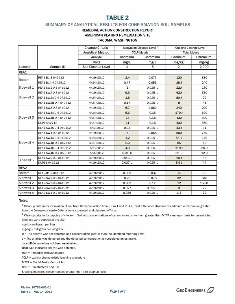
The results for the verification samples collected from REA 1 and REA 2 are presented in Table 2.
The laboratory analytical data reports for remedial excavation verification samples are provided in
Appendix F. A data quality review was performed on the laboratory analytical data and the results
of the data quality review identified that the laboratory data was of acceptable for use for
verification of the extent of contamination. The report summarizing the data quality review is
provided in Appendix F.
Material excavated from each excavation area was stockpiled separately on site in Stockpiled
Materials Management Areas prior to transport off site for disposal. Samples were collected from
the stockpiled material to characterize the material for off site disposal. The laboratory analytical
data reports for stockpile samples are provided in Appendix G. A total of approximately 1,160 tons
of material was excavated from REA 1 and REA 2 and transported off site for disposal.
The remedial excavation areas were backfilled prior to capping of the Site. Backfill placement
activities in REA 1 and REA 2 were observed by a qualified representative of the Engineer and in-
place moisture/density tests were performed as necessary using a nuclear density gauge. In our
opinion, the in-place moisture/density tests indicated compaction of remedial excavation backfill
was in general accordance with project plans and specifications.
The following sections describe in more detail remedial excavation and backfill activities performed
at REA 1 and REA 2.
3.4.1. Remedial Excavation and Backfill of REA 1
The remedial excavation for REA 1 was completed between April 18 and May 3, 2012. REA 1 was
initially excavated to the limits identified in the project plans and specifications. A representative
of the Engineer collected verification samples from the sidewalls and base of REA 1 to evaluate
contaminant concentrations in comparison to Site cleanup levels. Where the sidewall or base
verification sample analytical results indicated material with contaminant concentrations greater

AMERICAN PLATING SITE – REMEDIAL ACTION CONSTRUCTION REPORT Tacoma, Washington
Page 8 | May 14, 2013 | GeoEngineers, Inc. File No. 10751-002-01
than the Site cleanup levels was present, AEC performed additional over-excavation.
Over-excavation of REA 1 was required on the northern sidewall, eastern sidewall, southern
sidewall and the base of the excavation based on verification sample results. Following the
additional over-excavation of the sidewalls and the base of the excavation, additional verification
samples were collected and analyzed and the results compared to the Site cleanup levels. The
over-excavation and verification sampling and analysis process was repeated until verification
sample results from the limits of the excavation were less than the Site cleanup levels at REA 1.
A total of 16 verification samples were collected within REA 1. The samples were analyzed for total
cadmium and chromium and Toxicity Characterization Leaching Procedure (TCLP) cadmium and
chromium in accordance with the Compliance Monitoring Plan (CMP) (GeoEngineers, 2011a) and
Sampling and Analysis Plan (SAP) (GeoEngineers, 2011b). The results for verification samples
collected at the final limits of the excavation and analyzed for TCLP cadmium and chromium
indicated that the concentrations of leachable cadmium and chromium in soil were either not
detected or detected at a concentration less than the Site cleanup levels (i.e., Dangerous Waste
Toxicity Characteristic Criteria). Therefore, no additional excavation was required. The results for
verification samples collected at the final limits of the excavation and analyzed for total cadmium
and chromium indicated that the concentrations of total cadmium in soil were greater than cleanup
levels based on unrestricted land use. Therefore, the soil remaining in the excavation required
capping in accordance with the Ecology-approved CAP for the Site. The results for the verification
samples collected from REA 1 are presented in Table 2. The approximate verification sample
locations and the final limits of REA 1 are presented in Figure 2.
Material excavated from REA 1 was stockpiled and sampled to characterize the material for off site
disposal. Section 3.6 includes additional detail concerning stockpile sampling and analysis. The
results of the sample analyses indicated that the stockpiled material was designated hazardous
waste. The material excavated from REA 1 was disposed of at the Waste Management Subtitle C
facility in Arlington, Oregon. A total of approximately 960 tons of material was excavated and
disposed off site from REA 1.
Groundwater was encountered at the bottom of the REA 1 excavation. Ballast material was placed
in the bottom of the excavation to approximately 1-foot above the water table to provide a suitable
subgrade for placing gravel base course backfill material in accordance with the project
specifications. Ballast backfill material was placed in the bottom of the REA 1 excavation on
May 4, 2012 and approximately 75 cubic yards of existing gravel base course was placed on top of
the ballast material on May 7, 2012. The base course was compacted with a Caterpillar CS-533E
vibratory roller. The remaining REA 1 excavation was backfilled with imported gravel borrow
material. The gravel borrow backfill was placed in approximate 1-foot lifts and compacted with the
vibratory roller. Backfill placement activities in REA 1 were observed by a qualified representative
of the Engineer and in-place moisture/density tests were performed as necessary using a nuclear
density gauge. In our opinion, the in-place moisture/density tests indicated compaction of
remedial excavation backfill was in general accordance with project plans and specifications.
REA 1 was backfilled with gravel borrow backfill material up to a pre-capping elevation prior to
placing capping materials.

AMERICAN PLATING SITE – REMEDIAL ACTION CONSTRUCTION REPORT Tacoma, Washington
May 14, 2013 | Page 9 File No. 10751-002-01
3.4.2. Remedial Excavation and Backfill of REA 2
The remedial excavation for REA 2 occurred on April 19, 2012. REA 2 was initially excavated to the
limits identified in the project plans and specifications. AEC performed additional excavation of the
southern side wall based on the visual observation of green stained soil. The stained soil was
removed and a representative of the Engineer collected verification samples from the sidewalls
and the base of REA 2 to evaluate contaminant concentrations in comparison to Site cleanup
levels.
A total of five verification samples were collected from within REA 2. The samples were analyzed
for total cadmium and chromium and TCLP cadmium and chromium in accordance with the Site
CMP (GeoEngineers, 2011) and SAP (GeoEngineers, 2011). The results for verification samples
collected at the limits of the excavation and analyzed for TCLP cadmium and chromium indicated
that the concentrations of leachable cadmium and chromium in soil were either not detected or
detected at concentrations less than the Site cleanup levels (i.e., Dangerous Waste Toxicity
Characteristic Criteria). Therefore, no additional excavation was required. The results for
verification samples collected at the limits of the excavation and analyzed for total cadmium and
chromium indicated that the concentrations of total cadmium in soil were greater than the cleanup
levels based on unrestricted land use. Therefore, the soil remaining in the excavation required
capping in accordance with the Ecology-approved CAP for the Site. The results for the verification
samples collected from REA 2 are presented in Table 2. Material excavated from REA 2 was
stockpiled and sampled to characterize the material for off site disposal. Section 3.6 includes
additional detail concerning stockpile sampling and analysis. The results of the sample analyses
indicated that the stockpiled material was designated solid waste. The material excavated from
REA 2 was disposed of at the LRI Subtitle D landfill in Graham, Washington. A total of
approximately 100 tons of material was excavated and disposed off site from REA 2.
The REA 2 remedial excavation was backfilled on April 25, 2012. Existing base course material
was placed in approximately 8 to 12-inch lifts. The backfill material was compacted with a
Whacker DP6065 plate compactor. Backfill placement activities in REA 2 were observed by a
qualified representative of the Engineer and in-place moisture/density tests were performed, as
necessary, using a nuclear density gauge. In our opinion, the in-place moisture/density tests
indicated compaction of remedial excavation backfill was in general accordance with project plans
and specifications. REA 2 was backfilled with existing base course material up to a pre-capping
elevation prior to placing capping materials.
3.5. Utility Corridor Excavation, Stormwater System Installation, and Backfill
Excavation of utility corridors was performed in three areas to allow for installation of two new
stormwater collection and treatment systems and a corridor for future utility installations to
support public park development. The three utility corridor areas were designated Utility Corridor
Area (UCA) 1, UCA 2, and UCA 3.
Material excavated from each utility corridor excavation area was stockpiled separately on site in
Stockpiled Materials Management Areas prior to transport off site for disposal. Samples were
collected from the stockpiled material to characterize the material for off site disposal. The
laboratory analytical data reports for stockpile samples area provided in Appendix G. A total of

AMERICAN PLATING SITE – REMEDIAL ACTION CONSTRUCTION REPORT Tacoma, Washington
Page 10 | May 14, 2013 | GeoEngineers, Inc. File No. 10751-002-01
approximately 430 tons of material was excavated from UCA 1, UCA 2, and UCA 3 and transported
off site for disposal.
Backfill placement activities in UCA 1, UCA 2, and UCA 3 were observed by a qualified
representative of the Engineer and in-place moisture/density tests were performed as necessary
using a nuclear density gauge. In our opinion, the in-place moisture/density tests indicated
compaction of utility corridor backfill was in general accordance with project plans and
specifications.
3.5.1. Utility Corridor Area 1
UCA 1, located on the northeast portion of the Site, was excavated to the limits described in the
plans and specifications on May 15, 2012. The western portion of UCA 1 was located within REA 1
and was excavated as a result of the remedial excavation in REA 1. The western portion of REA 1
had not been backfilled at the time that the eastern portion of the UCA 1 excavation was
performed.
Geotextile fabric was placed in the bottom and on the sidewalls of the eastern portion of the UCA 1
excavation prior to backfilling to demarcate the limits of the excavation for the future utility
corridor. Geotextile fabric was also placed on the bottom of the western portion of the UCA 1
excavation where the UCA 1 excavation crossed the REA 1 excavation to demarcate the limits of
the excavation for the future utility corridor. Geotextile fabric was not placed on the sidewalls of
the portion of the UCA 1 corridor that was within REA 1 as gravel barrow backfill material was
placed to a distance of 10 of more feet outside the limits (i.e., sidewalls) of the future utility
corridor alignment.
The portion of UCA 1 that was outside of REA 1 was backfilled and compacted with gravel borrow
backfill material up to a pre-capping elevation prior to placing capping materials. The portion of
UCA 1 located within REA 1 was backfilled as described in Section 3.4.1. The gravel borrow backfill
was placed in approximate one-foot lifts and compacted with a Caterpillar CS-533E vibratory roller.
Material excavated from UCA 1 that was outside of the limits of REA 1, was stockpiled and sampled
to characterize the material for off site disposal. Section 3.6 includes additional detail concerning
stockpile sampling and analysis. The results of the sample analyses indicated that the stockpiled
material was designated hazardous waste. The material excavated from UCA 1 outside of REA 1
was disposed of at the Waste Management Subtitle C facility in Arlington, Oregon. A total of
approximately 180 tons of material was excavated and disposed of off site from UCA 1.
3.5.2. Utility Corridor Area 2
UCA 2, located on the southern boundary of the Site, was excavated and a new stormwater
collection and treatment system was installed between May 31 and June 12, 2012.
Due to a conflict with an existing utility line (City of Tacoma sanitary sewer line), the location of UCA
2 and the new catch basins, seven-filter Contect stormwater vault, and stormwater piping were
modified from the project plans and specifications as approved by the Engineer. In general, the
new stormwater system components were installed approximately five to 10 feet north of the
original design location. The new stormwater system was connected to City manhole #5000

AMERICAN PLATING SITE – REMEDIAL ACTION CONSTRUCTION REPORT Tacoma, Washington
May 14, 2013 | Page 11 File No. 10751-002-01
located on the parcel south of the Site (i.e., Parcel No. 8950001791). The UCA 2 stormwater
system installation was observed by a representative of the City and the Engineer and was
completed in general accordance with the project plans and specifications.
Geotextile material was placed within the UCA 2 excavation, excluding the area between the new
Contect stormwater vault and the City manhole located on the parcel south of the Site, prior to
placing backfill materials. UCA 2 was then backfilled and compacted with pipe bedding and gravel
borrow material up to the pre-capping elevation prior to placing capping materials. The backfill
material was compacted with a Whacker DP6065 plate compactor and/or a vibratory plate
compactor attached to an excavator.
Material excavated from UCA 2 was stockpiled and sampled to characterize the material for off site
disposal. Section 3.6 includes additional detail concerning stockpile sampling and analysis. The
results of the sample analyses indicated that the stockpiled material was designated solid waste.
The material excavated from UCA 2 was disposed of at the LRI Subtitle D landfill in Graham,
Washington. A total of approximately 230 tons of material was excavated and disposed of off site
from UCA 2.
3.5.3. Utility Corridor Area 3
UCA 3, located on the northeast boundary of the Site, was excavated and a new stormwater
collection and treatment system was installed between May 8 and 17, 2012.
A new catch basin, three-filter Contech stormwater vault/catch basin, and stormwater piping was
installed and connected to the City stormwater manhole #601 located in East D Street. The UCA 3
stormwater system installation was observed by a representative of the City and the Engineer and
was completed in general accordance with the project plans and specifications.
Geotextile material was placed within the UCA 3 excavation prior to placing backfill materials. UCA
3 was then backfilled and compacted with pipe bedding and gravel borrow material up to a pre-
capping elevation prior to placing capping materials. The backfill material was compacted with a
Whacker DP6065 plate compactor and/or a vibratory plate compactor attached to an excavator.
Material excavated from UCA 3 was stockpiled and sampled to characterize the material for off site
disposal. Section 3.6 includes additional detail concerning stockpile sampling and analysis. The
results of the sample analyses indicated that the stockpiled material was designated solid waste.
The material excavated from UCA 3 was disposed of at the LRI Subtitle D landfill in Graham,
Washington. A total of approximately 20 tons of material was excavated and disposed off site from
UCA 3.
3.6. Material Management, Loading, Transport, and Disposal, or Recycling
As stated in previous sections, a separate stockpile management area was constructed for each
remedial and utility corridor excavation area before excavation activities began. Other materials,
such as trash, debris, clearing and grubbing vegetation, were also stockpiled separately until they
were transported off site for recycling or disposal. The stockpile management areas were
constructed in general accordance with the project plans and specifications.
AMERICAN PLATING SITE – REMEDIAL ACTION CONSTRUCTION REPORT Tacoma, Washington
Page 12 | May 14, 2013 | GeoEngineers, Inc. File No. 10751-002-01
Materials excavated and stockpiled from REA 1, REA 2, UCA 1, UCA 2, and UCA 3 were
characterized prior to transport off site for disposal. Stockpile characterization sampling and
analysis was performed in accordance with the CMP (GeoEngineers, 2011a) and SAP
(GeoEngineers, 2011b). Stockpile samples were analyzed for the following;
■ Total RCRA metals:
■ Diesel- and oil-range petroleum hydrocarbons;
■ Gasoline-range petroleum hydrocarbons;
■ Volatile organic compounds (VOCs); and
■ Total cyanide.
Follow up analyses for TCLP metals were also performed on samples in which the total
concentration of a specific metal or metals were detected at concentrations that were greater than
the 20 times rule. The results for TCLP analyses were used to further characterize stockpiled
material for disposal. The laboratory analytical reports for stockpile sample analyses are provided
in Appendix G. The landfill weight tickets for disposal of the stockpiled material are provided in
Appendix C.
The following sections further describe the stockpile characterization and disposal activities.
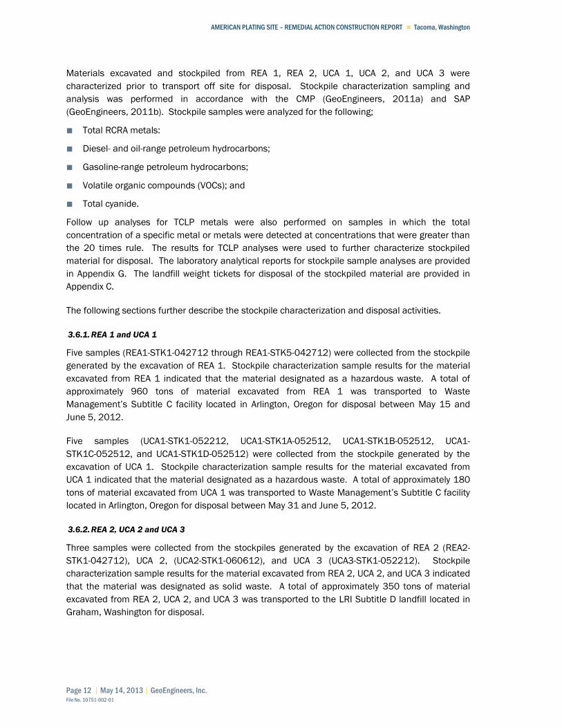
3.6.1. REA 1 and UCA 1
Five samples (REA1-STK1-042712 through REA1-STK5-042712) were collected from the stockpile
generated by the excavation of REA 1. Stockpile characterization sample results for the material
excavated from REA 1 indicated that the material designated as a hazardous waste. A total of
approximately 960 tons of material excavated from REA 1 was transported to Waste
Management’s Subtitle C facility located in Arlington, Oregon for disposal between May 15 and
June 5, 2012.
Five samples (UCA1-STK1-052212, UCA1-STK1A-052512, UCA1-STK1B-052512, UCA1-
STK1C-052512, and UCA1-STK1D-052512) were collected from the stockpile generated by the
excavation of UCA 1. Stockpile characterization sample results for the material excavated from
UCA 1 indicated that the material designated as a hazardous waste. A total of approximately 180
tons of material excavated from UCA 1 was transported to Waste Management’s Subtitle C facility
located in Arlington, Oregon for disposal between May 31 and June 5, 2012.
3.6.2. REA 2, UCA 2 and UCA 3
Three samples were collected from the stockpiles generated by the excavation of REA 2 (REA2-
STK1-042712), UCA 2, (UCA2-STK1-060612), and UCA 3 (UCA3-STK1-052212). Stockpile
characterization sample results for the material excavated from REA 2, UCA 2, and UCA 3 indicated
that the material was designated as solid waste. A total of approximately 350 tons of material
excavated from REA 2, UCA 2, and UCA 3 was transported to the LRI Subtitle D landfill located in
Graham, Washington for disposal.

AMERICAN PLATING SITE – REMEDIAL ACTION CONSTRUCTION REPORT Tacoma, Washington
May 14, 2013 | Page 13 File No. 10751-002-01
3.7. Site Grading and Capping
Site grading and capping activities were performed between April 10 and July 6, 2012. Grading
and capping activities generally progressed from the western to the eastern portions of the Site.
Grading activities began on April 10, 2012 on the western portion of the Site after installation of
the TESC including the western project boundary protection barrier. Grading followed by placement
of the initial two feet of capping material on the western portion of the Site was performed between
April 10 and April 26, 2012. The final one-foot layer of topsoil capping material was placed across
the western portion of the Site between June 12 and 18, 2012.
Grading and capping activities were completed on the remaining portions of the Site between April
20 and July 6, 2012. Grading and capping activities on the remaining portions of the Site generally
progressed as remedial excavation and backfill (i.e., REA 1 and REA 2), utility corridor excavation
and backfill (UCA 1, UCA 2, and UCA 3), and stockpiled material transport off site was completed.
The central portion of the Site encompassing REA 1, REA 2, UCA 1, and UCA 3 and the access
roadway was graded upon completion of excavation, verification sampling and analysis, and
backfill of the excavation areas. The southeastern portion of the Site was graded after excavated
materials that were stockpiled on the southeastern portion of the Site were transported off site for
disposal and excavation and backfilling of UCA 2 were completed. Capping of the central and
southeastern portions of the Site with gravel borrow, gravel base course, and gravel top course
materials was completed between June 6 and 26, 2012. Capping of the access roadway with
asphalt was performed on July 5 and 6, 2012.
Cap thickness verification was confirmed using a combination of methods and information that
included the following:
■ Physical measurements by AEC utilizing a laser level and survey rod and/or measuring tape
along the southern, western, and northern boundaries of the Site where excavation to a
minimum depth of three feet was performed to grade the Site so that the three foot thick cap
could be placed up to the Site boundaries.
■ Comparison of pre-capping surveyed elevations to post-capping surveyed elevations. AEC
provided surveys performed after Site grading had been completed in a specific area prior to
capping and surveys of the same areas upon completion of Site capping. The surveyed pre-
capping and post-capping elevations were compared to each other to identify where the
minimum cap thicknesses had been placed per the project plans and specifications during
capping activities. The comparison of the pre-capping and post-capping survey elevations also
identified locations where the minimum cap thickness appeared to not have been achieved.
■ Where the minimum cap thicknesses appeared to have not been achieved based on
comparison of the surveyed elevations, AEC performed posthole excavations to allow direct
measurement of the cap thickness. Cap thickness measurements were collected from each
posthole excavation that verified that the minimum cap thickness had been placed per the
project plans and specifications.
Cap thickness verification identified that the minimum requirements specified in the project plans
and specifications had been met at the Site.

AMERICAN PLATING SITE – REMEDIAL ACTION CONSTRUCTION REPORT Tacoma, Washington
Page 14 | May 14, 2013 | GeoEngineers, Inc. File No. 10751-002-01
Capping of the Site was observed by a qualified representative of the Engineer. The capping
material was placed in approximate one-foot lifts and compacted with a Caterpillar CS-533E
vibratory roller. In-place moisture/density tests were performed as necessary using a nuclear
density gauge. In our opinion, the in-place moisture/density tests indicated compaction of the
capping materials was in general accordance with project plans and specifications.
The following sections summarize the capping materials placed at the Site.
3.7.1. Three Foot Cap With Vegetative Surface
The western portion of the Site and the northern boundary of the Site were capped with a
3-foot-thick soil cap with a vegetated surface. The 3-foot-thick soil cap is comprised of the
following:
■ Approximately one foot of soil from an existing soil stockpile;
■ Approximately one foot of imported gravel borrow; and
■ Approximately one foot of imported top soil.
The western boundary of the Site includes a 3-foot-wide habitat enhancement area that was
planted with native plant species. Hydro-seed was applied across the remaining portion of the top
soil surface on the western portion of the Site.
3.7.2. Three Foot Cap With Gravel Surface
An area within the northwest portion of the Site as well as the eastern portion of the Site was
capped with a 3-foot-thick soil cap with gravel surface. The 3-foot-thick cap with gravel surface
consists of the following:
■ Approximately 33 inches of imported gravel borrow; and
■ Approximately 3 inches of imported top course gravel.
3.7.3. Eighteen Inch Soil And Asphalt Cap
The central portion of the Site was capped with a soil and asphalt cap. The soil and asphalt cap
consists of the following:
■ Approximately 13 inches of imported base course gravel;
■ Approximately 2 inches of imported top course gravel; and
■ Approximately 3 inches of asphalt.
3.8. Site Restoration
Site restoration activities were completed after Site grading and capping activities had been
performed and were completed in general accordance with the project plans and specifications.
The following sections further describe Site restoration activities.

AMERICAN PLATING SITE – REMEDIAL ACTION CONSTRUCTION REPORT Tacoma, Washington
May 14, 2013 | Page 15 File No. 10751-002-01
3.8.1. City ROW and Utility Restoration
The section of sidewalk and asphalt that was removed as part of the UCA 3 excavation and
installation of the new stormwater system was restored in general accordance with City code
requirements and the project specifications. The sidewalk was restored on May 25 and the
asphalt was restored on July 6, 2012.
3.8.2. Habitat Enhancement Area Plantings
The western boundary of the Site includes a three foot wide habitat enhancement area that was
restored by planting native plant species. The plantings were installed in the habitat enhancement
area between November 28 and December 3, 2012. Installation of the plants within the habitat
enhancement area was completed in general accordance with the project specifications and the
planting plan provided on Sheet C5.1 of project plans. AEC is responsible for maintaining the
habitat plantings and the habitat plantings are under warranty for one year from the planting date
in accordance with the requirements of the EDR and as specified on Plan Sheets C5.0 and C5.1.
3.8.3. New Groundwater Monitoring Well Installation
Three new monitoring wells; MW-20, MW-21, and MW-22; were installed upon completion of Site
grading and capping on the western portion of the Site. The new monitoring well borings were
drilled and the wells were installed by Cascade Drilling on May 14, 2012 using hollow-stem auger
drilling equipment. The monitoring wells were drilled and installed in general accordance with the
project plans and specifications. A licensed geologist observed the monitoring well drilling and
installation activities and documented the observations on boring logs. The well logs prepared for
the new monitoring wells are provided in Appendix H.
3.8.4. New Tree Installation
A new deciduous tree was planted on the western portion of the Site on December 3, 2012. The
Oregon ash tree installation was completed in general accordance with the project plans and
specifications.
3.8.5. Vegetative Surface Area Restoration
Hydro-seeding of the capped surface on the western portion of the Site and adjacent to the
northern boundary of the Site was performed on July 6, 2012. Hydro-seeding was completed in
general accordance with the project plans and specifications. Watering was performed periodically
to promote grass establishment starting in August 2012. Grass was generally observed to be
established in November 2012.
3.8.6. Fencing Restoration
Fence restoration activities were completed between July 10 and July 13, 2012. Site fencing was
installed along the northern, northeastern, and southwestern property boundaries and in the
central portion of the Site west and adjacent to the asphalt roadway. Fencing materials, including
existing chain-link fencing and associated hardware salvaged during Site preparation activities,
was re-installed in general accordance with the project specifications and plans.

AMERICAN PLATING SITE – REMEDIAL ACTION CONSTRUCTION REPORT Tacoma, Washington
Page 16 | May 14, 2013 | GeoEngineers, Inc. File No. 10751-002-01
4.0 CLOSURE
Remedial construction activities were performed at the American Plating Site in Tacoma, Washington between April 9, 2012 and December 3, 2012. The remedial action was conducted by the FWDA to satisfy requirements of a Prospective Purchaser Consent Decree (CD) (No. 03 2 14513 6) issued by Ecology and to address contamination resulting from releases from past metal plating operations at the Site. The remedial actions completed at the Site implemented the preferred cleanup alternative specified in the Ecology-approved CAP prepared for the Site.
The remedial actions included excavation and capping of soil with contaminant concentrations greater than the Site cleanup levels in general accordance with the EDR plans and specifications. Verification soil samples collected at the limits of the remedial excavations indicate that materials with TCLP cadmium and chromium concentrations greater than the Site cleanup levels were removed from the remedial excavations. Following backfilling of the remedial excavations, the entire Site was graded and capped. Restoration activities were performed upon completion of Site capping activities.
It is our opinion that the remediation activities at the Site were performed in general accordance with the EDR plans and specifications prepared for remediation of the Site.
5.0 REFERENCES
GeoEngineers, 2003. Cleanup Action Plan (CAP) American Plating Site Remediation Project. November 24, 2003.
GeoEngineers, 2011a. Draft Compliance Monitoring Plan (CMP) American Plating Site Remediation Project. October 4, 2011.
GeoEngineers, 2011b. Draft Sampling and Analysis Plan (SAP) American Plating Site Remediation Project. October 4, 2011.
GeoEngineers, 2012. Engineering Design Report (EDR) American Plating Site Remediation Project. January 27, 2012.
6.0 LIMITATIONS
This Remedial Action Construction report has been prepared for use by the Foss Waterway Development Authority. GeoEngineers observed performance of the remedial action construction activities at the American Plating Site, Tacoma, Washington and prepared this remedial action construction report in accordance with the scope and limitations of the project proposal.
Within the limitations of scope, schedule, and budget, our services have been executed in accordance with the generally accepted environmental science practices for Remedial Action Construction reporting at the time this report was prepared. No warranty or other conditions, express or implied, should be understood.
Please refer to Appendix H titled “Report Limitations and Guidelines for Use” for additional information pertaining to use of this report.

Material Type Gravel Borrow Base Coarse Top Coarse Top Soil
Sample Name GRAVEL BORROW BASE COARSE - 1 TOP COARSE - 1 TOPSOIL - 1
Date 3/30/2012 3/30/2012 3/30/2012 4/13/2012
Analytes
Metals (mg/kg)
Antimony 1.7 U 2.3 U 2.5 U 3.1 U 2 32
Arsenic 1.7 2.3 U 2.5 U 7.4 202 0.673
Beryllium 0.27 0.19 0.22 0.67 - 160
Cadmium 0.29 U 0.39 U 0.42 U 0.59 2 -
Chromium 13 J 8.4 J 9.9 J 24 2,000 120,000
Chromium, Hexavalent 0.24 U 0.24 U 0.27 U 0.27 U 19 240
Copper 13 12 14 21 - 3,200
Lead 1.8 1.5 2.3 2.5 250 -
Mercury 0.023 0.014 U 0.014 U 0.043 2 -
Nickel 16 6.8 10 33 - 1,600
Selenium 2.9 U 3.9 U 4.2 U 5.2 UI - 400
Silver 0.58 U 0.77 U 0.84 U 1 U - 400
Thallium 2.9 U 3.9 U 4.2 U 5.2 UI - -
Zinc 26 18 26 37 - 24,000
Total Petroleum Hydrocarbons (mg/kg)
Gasoline-Range Hydrocarbons 3.6 U 5.3 U 5.3 U 4.6 U 100 -
Diesel-Range Hydrocarbons 25 U 26 U 26 U 27 U 2,000 -
Oil-Range Hydrocarbons 50 U 52 U 51 U 53 U 2,000 -
PAHs (µg/kg)
1-Methylnaphthalene 5 U 5.1 U 5 U 5.4 U - 24,000
2-Methylnaphthalene 5 U 5.1 U 5 U 5.4 U - 320,000
Acenaphthene 5 U 5.1 U 5 U 5.4 U - 4,800,000
Acenaphthylene 5 U 5.1 U 5 U 5.4 U - -
Anthracene 5 U 5.1 U 5 U 5.4 U - 24,000,000
Benzo(a)anthracene 5 U 5.1 U 5 U 5.4 U - 1,400
Benzo(a)pyrene 5 U 5.1 U 5 U 5.4 U 100 140
Benzo(b)fluoranthene 5 U 5.1 U 5 U 5.4 U - 1,400
Benzo(ghi)perylene 5 U 5.1 U 5 U 5.4 U - -
Benzo(k)fluoranthene 5 U 5.1 U 5 U 5.4 U - 14,000
Chrysene 5 U 5.1 U 5 U 5.4 U - 140,000
Dibenzo(a,h)anthracene 5 U 5.1 U 5 U 5.4 U - 140
Fluoranthene 5 U 5.1 U 5 U 5.4 U - 3,200,000
Fluorene 5 U 5.1 U 5 U 5.4 U - 3,200,000
Indeno(1,2,3-cd)pyrene 5 U 5.1 U 5 U 5.4 U - 1,400
Naphthalene 5 U 5.1 U 5 U 5.4 U 5,000 1,600,000
Phenanthrene 5 U 5.1 U 5 U 5.4 U - -
Pyrene 5 U 5.1 U 5 U 5.4 U - 2,400,000Total cPAH TEQ (ND=0.5RL)4
3.775 UT 3.8505 UT 3.775 UT 4.077 UT 100
VOCs (µg/kg)
1,1,1,2-Tetrachloroethane 0.93 U 1 U 0.98 U 1.2 U - 38,000
1,1,1-Trichloroethane 0.93 U 1 U 0.98 U 1.2 U 2,000 160,000,000
1,1,2,2-Tetrachloroethane 1.9 U 2 U 2 U 2.3 U - 5,000
1,1,2-Trichloroethane 0.93 U 1 U 0.98 U 1.2 U - 18,000
1,1-Dichloroethane 0.93 U 1 U 0.98 U 1.2 U - 16,000,000
1,1-Dichloroethene 4.6 U 5 U 4.9 U 5.8 U - 4,000,000
1,1-Dichloropropene 0.93 U 1 U 0.98 U 1.2 U - -
1,2,3-Trichlorobenzene 1.9 U 2 U 2 U 2.3 U - -
1,2,3-Trichloropropane 0.93 U 1 U 0.98 U 1.2 U - 33.3
1,2,4-Trichlorobenzene 1.9 U 2 U 2 U 2.3 U - 35,000
1,2,4-Trimethylbenzene 1.9 U 2 U 2 U 2.3 U - -
1,2-Dibromo-3-Chloropropane 1.9 U 2 U 2 U 2.3 U - 1,250
1,2-dibromoethane (EDB) 0.93 U 1 U 0.98 U 1.2 U 5 500
1,2-Dichlorobenzene (o-Dichlorobenzene) 0.93 U 1 U 0.98 U 1.2 U - 7,200,000
1,2-Dichloroethane (EDC) 0.93 U 1 U 0.98 U 1.2 U - 11,000
1,2-Dichloropropane 0.93 U 1 U 0.98 U 1.2 U - -
1,3,5-Trimethylbenzene 4.6 U 5 U 4.9 U 5.8 U - 800,000
1,3-Dichlorobenzene (m-Dichlorobenzene) 0.93 U 1 U 0.98 U 1.2 U - -
1,3-Dichloropropane 0.93 U 1 U 0.98 U 1.2 U - -
1,4-Dichlorobenzene (p-Dichlorobenzene) 0.93 U 1 U 0.98 U 1.2 U - -
2,2-Dichloropropane 0.93 U 1 U 0.98 U 1.2 U - -
2-Chlorotoluene 1.9 U 2 U 2 U 2.3 U - 1,600,000
4-Chlorotoluene 1.9 U 2 U 2 U 2.3 U - -
Benzene 0.93 U 1 U 0.98 U 1.2 U 30 18,000
Bromobenzene 1.9 U 2 U 2 U 2.3 U - -
Bromochloromethane 0.93 U 1 U 0.98 U 1.2 U - -
Bromodichloromethane 0.93 U 1 U 0.98 U 1.2 U - 16,000
Bromoform (Tribromomethane) 0.93 U 1 U 0.98 U 1.2 U - 130,000
Bromomethane 0.93 U 1 U 0.98 U 1.2 U - 110,000
Carbon Tetrachloride 0.93 U 1 U 0.98 U 1.2 U - 14,300
Chlorobenzene 0.93 U 1 U 0.98 U 1.2 U - 1,600,000
Chloroethane 0.93 U 1 U 0.98 U 1.2 U - -
Chloroform 0.93 U 1 U 0.98 U 1.2 U - 800,000
Chloromethane 0.93 U 1 U 0.98 U 1.2 U - -
Cis-1,2-Dichloroethene 0.93 U 1 U 0.98 U 1.2 U - 160,000
Cis-1,3-Dichloropropene 0.93 U 1 U 0.98 U 1.2 U - -
Dibromochloromethane 0.93 U 1 U 0.98 U 1.2 U - 12,000
Dibromomethane 0.93 U 1 U 0.98 U 1.2 U - 800,000
MTCA
Method A 1
MTCA
Method B 1
TABLE 1SUMMARY OF ANALYTICAL RESULTS FOR BACKFILL AND CAPPING MATERIAL
REMEDIAL ACTION CONSTRUCTION REPORTAMERICAN PLATING REMEDIATION SITE
TACOMA, WASHINGTON
File No. 10751-002-01Table 1 | May 14, 2013 Page 1 of 3

Material Type Gravel Borrow Base Coarse Top Coarse Top Soil
Sample Name GRAVEL BORROW BASE COARSE - 1 TOP COARSE - 1 TOPSOIL - 1
Date 3/30/2012 3/30/2012 3/30/2012 4/13/2012
Analytes
MTCA
Method A 1
MTCA
Method B 1
Dichlorodifluoromethane (CFC-12) 0.93 U 1 U 0.98 U 1.2 U - 16,000,000
Ethylbenzene 0.93 U 1 U 0.98 U 1.2 U 6,000 8,000,000
Hexachlorobutadiene 0.93 U 1 U 0.98 U 1.2 U - 13,000
Isopropylbenzene (Cumene) 1.9 U 2 U 2 U 2.3 U - 8,000,000
Methyl t-butyl ether 0.93 U 1 U 0.98 U 1.2 U 100 -
Methylene Chloride 14 U 15 U 15 U 18 U 20 130,000
Naphthalene 4.6 U 5 U 4.9 U 5.8 U 5,000 1,600,000
n-Butylbenzene 1.9 U 2 U 2 U 2.3 U - -
n-Propylbenzene 0.93 U 1 U 0.98 U 2.3 U - -
p-Isopropyltoluene 1.9 U 2 U 2 U 2.3 U - -
Sec-Butylbenzene 1.9 U 2 U 2 U 2.3 U - -
Styrene 1.9 U 2 U 2 U 2.3 U - 16,000,000
Tert-Butylbenzene 1.9 U 2 U 2 U 2.3 U - -
Tetrachloroethene 0.93 U 1 U 0.98 U 1.2 U 50 480,000
Toluene 1.9 U 2 U 2 U 2.3 U 7,000 6,400,000
Trans-1,2-Dichloroethene 0.93 U 1 U 0.98 U 1.2 U - 1,600,000
Trans-1,3-Dichloropropene 0.93 U 1 U 0.98 U 1.2 U - -
Trichloroethene (TCE) 0.93 U 1 U 0.98 U 1.2 U 30 1,200
Trichlorofluoromethane (CFC-11) 0.93 U 1 U 0.98 U 1.2 U - 24,000,000
Vinyl Chloride 0.93 U 1 U 0.98 U 1.2 U - 670
Xylene, m-,p- 1.9 U 2 U 2 U 2.3 U 9,000 16,000,000
Xylene, o- 0.93 U 1 U 0.98 U 1.2 U 9,000 16,000,000
SVOCs (µg/kg)
1,2,4-Trichlorobenzene 50 U 51 U 50 U 54 U - 800,000
1,2-Dichlorobenzene (o-Dichlorobenzene) 55 U 56 U 55 U 60 U - 7,200,000
1,3-Dichlorobenzene (m-Dichlorobenzene) 50 U 51 U 50 U 54 U - -
1,4-Dichlorobenzene (p-Dichlorobenzene) 50 U 51 U 50 U 54 U - -
2,2'-Oxybis[1-chloropropane] 250 U 250 U 250 U 270 U - 14,000
2,4,5-Trichlorophenol 100 U 100 U 100 U 110 U - 8,000,000
2,4,6-Trichlorophenol 150 U 150 U 150 U 160 U - 81,000
2,4-Dichlorophenol 100 U 100 U 100 U 110 U - 240,000
2,4-Dimethylphenol 100 U 100 U 100 U 110 U - 1,600,000
2,4-Dinitrophenol 1,000 U 1,000 U 1,000 U 1,100 U - 160,000
2,4-Dinitrotoluene 100 U 100 U 100 U 110 U - 160,000
2,6-Dinitrotoluene 100 U 100 U 100 U 110 U - 81,000
2-Chloronaphthalene 20 U 20 U 20 U 22 U - 6,400,000
2-Chlorophenol 100 U 100 U 100 U 110 U - 400,000
2-Nitroaniline 100 U 100 U 100 U 110 U - 800,000
2-Nitrophenol 100 U 100 U 100 U 110 U - -
3,3'-Dichlorobenzidine 200 U 200 U 200 U 220 U - 2,200
3-Nitroaniline 100 U 100 U 100 U 110 U - -
4,6-Dinitro-2-Methylphenol 1,000 U 1,000 U 1,000 U 1,100 U - -
4-Bromophenyl phenyl ether 100 U 100 U 100 U 110 U - -
4-Chloro-3-Methylphenol 100 U 100 U 100 U 110 U - -
4-Chloroaniline 100 U 100 U 100 U 110 U - 500
4-Chlorophenyl-Phenylether 100 U 100 U 100 U 110 U - -
4-Nitroaniline 100 U 100 U 100 U 110 U - -
4-Nitrophenol (p-Nitrophenol) 1,000 U 1,000 U 1,000 U 1,100 U - -
Benzoic Acid 2,500 U 2,500 U 2,500 U 2,700 U - 320,000,000
Benzyl Alcohol 100 U 100 U 100 U 110 U - 8,000,000
Bis(2-Chloroethoxy)Methane 100 U 100 U 100 U 110 U - -
Bis(2-Chloroethyl)Ether 100 U 100 U 100 U 110 U - 910
Bis(2-Ethylhexyl) Phthalate 610 U 610 U 600 U 650 U - 71,000
Butyl benzyl phthalate 200 U 200 U 200 U 220 U - 530,000
Carbazole 100 U 100 U 100 U 110 U - -
Dibenzofuran 100 U 100 U 100 U 110 U - 80,000
Dibutyl phthalate 500 U 510 U 500 U 540 U - 8,000,000
Diethyl phthalate 200 U 200 U 200 U 220 U - 64,000,000
Dimethyl phthalate 100 U 100 U 100 U 110 U - -
Di-N-Octyl Phthalate 500 U 510 U 500 U 540 U - -
Hexachlorobenzene 50 U 51 U 50 U 54 U - 630
Hexachlorobutadiene 50 U 51 U 50 U 54 U - 13,000
Hexachlorocyclopentadiene 100 U 100 U 100 U 110 U - 480,000
Hexachloroethane 100 U 100 U 100 U 110 U - 71,000
Isophorone 100 U 100 U 100 U 110 U - 1,100,000
Nitrobenzene 100 U 100 U 100 U 110 U - 160,000
N-Nitrosodi-n-propylamine 100 U 100 U 100 U 110 U - 140
N-Nitrosodiphenylamine 50 U 51 U 50 U 54 U - 200,000
o-Cresol (2-methylphenol) 100 U 100 U 100 U 110 U - 4,000,000
p-Cresol (4-methylphenol) 200 U 200 U 200 U 220 U - 400,000
Pentachlorophenol 200 U 200 U 200 U 220 U - 2,500
Phenol 100 U 100 U 100 U 110 U - 24,000,000
PCB Aroclors (µg/kg)
PCB-aroclor 1016 10 U 10 U 9.8 U 11 UJ - 5,600
PCB-aroclor 1221 11 U 11 U 11 U 12 UJ - -
PCB-aroclor 1232 11 U 11 U 11 U 12 UJ - -
PCB-aroclor 1242 10 U 10 U 9.8 U 11 UJ - -
PCB-aroclor 1248 10 U 10 U 9.8 U 11 UJ - -
PCB-aroclor 1254 10 U 10 U 9.8 U 11 UJ - 500
PCB-aroclor 1260 10 U 10 U 9.8 U 11 UJ - 500
Total Aroclors 11 UT 11 UT 11 UT 12 UJT 1,000 500
File No. 10751-002-01Table 1 | May 14, 2013 Page 2 of 3

Material Type Gravel Borrow Base Coarse Top Coarse Top Soil
Sample Name GRAVEL BORROW BASE COARSE - 1 TOP COARSE - 1 TOPSOIL - 1
Date 3/30/2012 3/30/2012 3/30/2012 4/13/2012
Analytes
MTCA
Method A 1
MTCA
Method B 1
Pesticiedes (µg/kg)
4,4'-DDD 2 U 2 U 2 U 2.2 U - -
4,4'-DDE 2 U 2 U 2 U 2.2 U - -
4,4'-DDT 2 U 2 U 2 U 2.2 U 3,000 -
Aldrin 1 U 1 U 0.98 U 1.1 U - -
Alpha-BHC 1 U 1 U 0.98 U 1.1 U - -
alpha-Chlordane (cis) 1 U 1 U 0.98 U 1.1 U - -
beta or gamma-Chlordane (trans) 1 U 1 U 0.98 U 1.1 U - -
Beta-BHC 1 U 1 U 0.98 U 1.1 U - -
Delta-BHC 1 U 1 U 0.98 U 1.1 U - -
Dieldrin 2 U 2 U 2 U 2.2 U - -
Endosulfan I 1 U 1 U 0.98 U 1.1 U - -
Endosulfan II 2 U 2 U 2 U 2.2 U - -
Endosulfan Sulfate 2 U 2 U 2 U 2.2 U - -
Endrin 2 U 2 U 2 U 2.2 U - -
Endrin Aldehyde 2 U 2 U 2 U 2.2 U - -
Endrin Ketone 2 U 2 U 2 U 2.2 U - -
Heptachlor 2 U 2 U 2 U 2.2 U - -
Heptachlor Epoxide 1 U 1 U 0.98 U 1.1 U - -
Lindane (Gamma-BHC) 1 U 1 U 0.98 U 1.1 U 10 -
Methoxychlor 10 U 10 U 9.8 U 11 U - -
Toxaphene 100 U 100 U 98 U 110 U - -
Notes: 1 MTCA cleanup levels for unrestricted land use.2 Based on background arsenic concentrations in Washington State.3 Concentration below background for Washington State. Therefore, background concentration is applicable for screening the analytical results for backfill and capping material.
µg/kg = microgram per kilogram
mg/kg = milligram per kilogram
U = The analyte was not detected at a concentration greater than the identified reporting limit.
J = The analyte was detected and the detected concentration is considered an estimate.
T = The analyte total concentration was calculated by GeoEngineers.
I = The reporting limit was elevated due to chromatographic overlap with either another analyte or a compound outside the analysis.
- - = MTCA value has not been established.
Bold indicates analyte was detected.
MTCA = Model Toxics Control Act
ULU = Unrestricted Land Use
4 Total carcinogenic Polycyclic Aromatic Hydrocarbon (cPAH) calculated using toxic equivalent (TEQ) methodology relative to benzo(a)pyrene. cPAHs that were not detected were assigned a value of one half of the detection limit for these calculations.
File No. 10751-002-01Table 1 | May 14, 2013 Page 3 of 3
Cleanup CriteriaAnalytical Method
Analyte Cadmium Chromium Cadmium Chromium
Units mg/L mg/L mg/kg mg/kgLocation Sample ID Site Cleanup Level 1 5 2 2,000
REA1
REA1-B1-3-041912 4/19/2012 2.4 0.077 120 380
REA1-B1A-4-042412 4/24/2012 0.47 0.053 38 J 240
Sidewall 1 REA1-SW1-0-3-041912 4/19/2012 1 0.025 U 220 130
REA1-SW2-0-3-041912 4/19/2012 9.3 0.025 U 630 530
REA1-SW2A-0-4-042412 4/24/2012 1.5 0.025 U 80 J 90
REA1-SW2B-D-4-042712 4/27/2012 0.17 0.025 U 9 41
REA1-SW3-0-3-041912 4/19/2012 6.7 0.069 240 290
REA1-SW3A-0-4-042412 4/24/2012 5.6 0.15 170 J 690
REA1-SW3B-D-4-042712 4/27/2012 13 0.16 430 300
DUPE-042712 4/27/2012 11 0.16 430 360
REA1-SW3C-0-4-050112 5/1/2012 0.93 0.025 U 43 J 31
REA1-SW4-0-3-041912 4/19/2012 5 0.058 500 750
REA1-SW4A-0-4-042412 4/24/2012 1.2 0.025 U 58 J 140
REA1-SW4B-D-4-042712 4/27/2012 2.3 0.025 U 85 53
REA1-SW4C-0-4-050112 5/1/2012 4.3 0.025 U 110 J 25 J
REA1-SW4D-0-4-050312 5/3/2012 0.01 U 0.025 U 0.5 U 12 J
REA1-SW5-0-3-041912 4/19/2012 0.015 J 0.025 U 10 J 55
DUPE1-041912 4/19/2012 0.037 J 0.025 U 5.9 J 44
REA2Bottom REA2-B1-2-041912 4/19/2012 0.033 0.037 3.9 95
Sidewall 1 REA2-SW1-0-2-041912 4/19/2012 0.26 0.078 32 840
Sidewall 2 REA2-SW2-0-2-041912 4/19/2012 0.083 0.17 12 1,200
Sidewall 3 REA2-SW3-0-2-041912 4/19/2012 0.027 0.025 U 3 79
Sidewall 4 REA2-SW4-0-2-041912 4/19/2012 0.036 0.025 U 1.4 32
Notes:
mg/L = milligram per liter
mg/kg = milligram per kilogram
U = The analyte was not detected at a concentration greater than the identified reporting limit.
J = The analyte was detected and the detected concentration is considered an estimate.
- - = MTCA value has not been established.
Bold type indicates analyte was detected.
REA = Remedial excavation area
TCLP = toxicity characteristic leaching procedure
MTCA = Model Toxics Control Act
ULU = Unrestricted Land Use
Shading indicates concentrations greater than site cleanup level.
TCLP-Metals Total Metals
1 Cleanup criteria for excavation of soil from Remedial Action Area (REA) 1 and REA 2. Soil with concentrations of cadmium or chromium greater than the Dangerous Waste Criteria were excavated and disposed off site.2 Cleanup criteria for capping of site soil . Soil with concentrations of cadmium and chromium greater than MTCA cleanup criteria for unrestricted land use were capped at the site.
Sidewall 5
Sidewall 4
TABLE 2SUMMARY OF ANALYTICAL RESULTS FOR CONFIRMATION SOIL SAMPLES
REMEDIAL ACTION CONSTRUCTION REPORTAMERICAN PLATING REMEDIATION SITE
TACOMA, WASHINGTON
Sidewall 3
Capping Cleanup Level 2Excavation Cleanup Level 1
Bottom
Sidewall 2
File No. 10751-002-01Table 2 | May 14, 2013 Page 1 of 1

§̈¦5
§̈¦705
§̈¦705
S L St
S M S
t
S G S
t E 34Th St
S Yakima Ave
E M
St
E Dock S
t
Fawcett Ave
S 37Th St
S I St
S 9Th St
S Sheridan Ave
S 15Th St
E R St
S Cushm
an Ave
E 35Th St
E 25Th St
G
E G
St
S 21St St
S 13Th St
S 7Th St
E D St
E F St
C
E K
St
S Ainsw
orth Ave
A S
t
S D
St
E E St
S 16Th St
S 8Th St
E 26Th St
Portland Ave
Martin Luther K
ing Jr Way
E B
St
Olympic St
S C St
S 35Th St
E Harrison St
S J
St
S K
St
Wiley Ave
E 21St St S Court E
St
Com
merce S
t
S 14Th St
S 23Rd St
E I S
t
S 27Th St
E 29Th St
E 18Th St
Broadway
E T St
Delin S
t
E 28Th St
E N St
S 36Th St
E 27Th St
S 17Th St
E 30Th St
E Fairbanks St
N K St
S Fawcett A
ve
Court E
S Court D
St
Thorne Rd
E 19Th St
S 10Th St
E 31St St
S 28Th St
N 4T
h St
S 5Th St
E H
owe
St
N L St
E 32Nd St
S Th
omps
on A
ve
N J St
E J St
S 32Nd St
Cleveland St
S 34Th St
E Milwaukee W
aterway Rd
S A
lask
a S
t
L
Middle W
aterway
F E
Spo
kane
St
Stewart St
Cleveland Way
E Wright Ave
A
E Marc St
S Court C
St
N 3R
d St
S 30Th St
B St
D
Doc
k S
t
Saint Helens Ave
11Th Pl
S 18Th St
E Columbia Ave
Mckinley Rd
S 4Th St
Cliff A
ve
E 37Th St
S Wright Ave
E Q
St
Busti St
S C
hand
ler S
t
E C St
S A
sotin
St
S Altheim
er St
S 29Th St
S 20Th St
S S
awye
r St
E Morton St
S H
ood
St
Mckinley A
ve
3Rd St
Court F S
t
S 22Nd St
E Lennox Pl E Division Ln
E J
St
S A
insw
orth
Ave
A
A St
G
E N St
S A
lask
a S
t
A
S S
herid
an A
ve
S 32Nd St
S 30Th St
E K
St
S C St
E 29Th St
S C
ushm
an A
ve
E G S
t
S 27Th St
E 30Th St
S 23Rd St
S G S
t
S 4Th St
S L
St
E K S
t
E Division Ln
S G S
t
S S
herid
an A
ve
Fawcett Ave
E D St
S A
lask
a S
t
Broadway
S 5Th St
E E
St
S 28Th St
S Wright Ave
E J St
E M S
t
Court E
S 4Th St
E 32Nd St
A
E Marc St
E F
St
A St
S J St
E F St
E D St
E I St E J S
t
E Wright Ave
E 35Th St
E N St
E 18Th St
C
E K S
t
S Court E St
UV509
UV167
S I St
Pacific Ave
Tacoma Ave S
E 11Th St
S 25Th St
S 11Th St
S 19Th St
Center St
E D St
6Th Ave
Linco
ln Ave
S 12Th St
Puyallup Ave
Milwaukee W
ay
E L
St
Eells St
Mck
inle
y Av
e
Saint Paul Ave E 15Th St
E L St E D St
μ
SITE
Vicinity Map
Figure 1
Engineering Design ReportAmerican Plating Site Remediation Project
Tacoma, Washington
Pierce
King
Thurston
Kitsap
Mason
§̈¦5
§̈¦705
UV16UV167
UV512UV161
UV18UV163
W a s h i n g t o n 2,000 2,0000
Feet
Data Sources: ESRI Data & Maps
Notes:1. The locations of all features shown are approximate.2. This drawing is for information purposes. It is intended to assist in showing features discussed in an attached document. GeoEngineers, Inc. can not guarantee the accuracy and content of electronic files. The master file is stored by GeoEngineers, Inc. and will serve as the official record of this communication.3. It is unlawful to copy or reproduce all or any part thereof, whether for personal use or resale, without permission.
Projection: NAD 1983 UTM Zone 10N
Offi
ce: T
AC
Pat
h: P
:\10\
1075
1002
\GIS
\107
5100
201_
ED
R_F
1.m
xdM
ap R
evis
ed: 1
6 D
ecem
ber 2
011
s
yi
Remedial Action Construction Report


APPENDIX A American Plating Site Engineering Design Report

APPENDIX B Water Characterization Laboratory Analytical Data
Reports

APPENDIX C Materials Recycling and Disposal Documentation
APPENDIX D Well Decommissioning Reports

APPENDIX E Backfill and Capping Material Laboratory Analytical
Data Reports and Data Quality Review

APPENDIX F Verification Sampling Laboratory Analytical Data
Reports and Data Quality Review

Page 2 | May 14, 2013 | GeoEngineers, Inc. File No. 10751-002-01
APPENDIX G Stockpile Sampling Laboratory Analytical Data
Reports

APPENDIX H Report Limitations and Guidelines for Use
AMERICAN PLATING SITE – REMEDIAL ACTION CONSTRUCTION REPORT Tacoma, Washington
May 14, 2013 | Page H-1 File No. 10751-002-01
APPENDIX H
REPORT LIMITATIONS AND GUIDELINES FOR USE1
This appendix provides information to help you manage your risks with respect to the use of this
report.
Environmental Services Are Performed for Specific Purposes, Persons and Projects
GeoEngineers has completed this Remedial Action Construction Report for the American Plating
Site in general accordance with the scope and limitations of our proposal, dated July 25, 2011.
This report has been prepared for the exclusive use of Foss Waterway Development Authority, their
authorized agents and regulatory agencies. This report is not intended for use by others, and the
information contained herein is not applicable to other properties.
GeoEngineers structures our services to meet the specific needs of our clients. For example, an
ESA study conducted for a property owner may not fulfill the needs of a prospective purchaser of
the same property. Because each environmental study is unique, each environmental report is
unique, prepared solely for the specific client and property. No one except Foss Waterway
Development Authority should rely on this environmental report without first conferring with
GeoEngineers. Use of this report is not recommended for any purpose or project except the one
originally contemplated.
This Environmental Report is Based on a Unique Set of Project-Specific Factors
This report has been prepared for the American Plating Site. GeoEngineers considered a number
of unique, project-specific factors when establishing the scope of services for this project and
report. Unless GeoEngineers specifically indicates otherwise, it is important not to rely on this
report if it was:
■ not prepared for you,
■ not prepared for your project,
■ not prepared for the specific site explored, or
■ completed before important project changes were made.
If important changes are made to the project or property after the date of this report, we
recommend that GeoEngineers be given the opportunity to review our interpretations and
recommendations. Based on that review, we can provide written modifications or confirmation, as
appropriate.
Reliance Conditions for Third Parties
Our report was prepared for the exclusive use of our Client. No other party may rely on the product
of our services unless we agree to such reliance in advance and in writing. This is to provide our
1 Developed based on material provided by ASFE, Professional Firms Practicing in the Geosciences; www.asfe.org.

AMERICAN PLATING SITE – REMEDIAL ACTION CONSTRUCTION REPORT Tacoma, Washington
Page H-2 | May 14, 2013 | GeoEngineers, Inc. File No. 10751-002-01
firm with reasonable protection against open-ended liability claims by third parties with whom there
would otherwise be no contractual limits to their actions. Within the limitations of scope, schedule
and budget, our services have been executed in accordance with our Agreement with the Client
and generally accepted environmental practices in this area at the time this report was prepared.
Environmental Regulations Are Always Evolving
Some substances may be present in the vicinity of the subject property in quantities or under
conditions that may have led, or may lead, to contamination of the subject property, but are not
included in current local, state or federal regulatory definitions of hazardous substances or do not
otherwise present current potential liability. GeoEngineers cannot be responsible if the standards
for appropriate inquiry, or regulatory definitions of hazardous substances, change or if more
stringent environmental standards are developed in the future.
Conditions Can Change
This environmental report is based on conditions that existed at the time the study was performed.
The findings and conclusions of this report may be affected by the passage of time, by man-made
events such as construction on or adjacent to the subject property, by new releases of hazardous
substances, or by natural events such as floods, earthquakes, slope instability or groundwater
fluctuations. Please contact GeoEngineers before applying this report for its intended purpose so
that GeoEngineers may evaluate whether changed conditions affect the continued applicability of
the report.
Most Environmental Findings Are Professional Opinions
Our interpretations of site conditions are based on field observations and analytical data from
widely spaced sampling locations at the subject property. Site exploration identifies subsurface
conditions only at those points where subsurface tests are conducted or samples are taken.
GeoEngineers reviewed field and laboratory data and then applied our professional judgment to
render an informed opinion about subsurface conditions throughout the property. Actual
subsurface conditions may differ, sometimes significantly, from those indicated in this report. Our
report, conclusions and interpretations should not be construed as a warranty of the subsurface
conditions.
Read These Provisions Closely
It is important to recognize that the geoscience practices (geotechnical engineering, geology and
environmental science) are less exact than other engineering and natural science disciplines.
Without this understanding, there may be expectations that could lead to disappointments, claims
and disputes. GeoEngineers includes these explanatory “limitations” provisions in our reports to
help reduce such risks. Please confer with GeoEngineers if you need to know more about how
these “Report Limitations and Guidelines for Use” apply to your project or property.