
AMERICAN-LINCOLN - Cleaning Equipment Parts.com before attempting to operate this machine. ... Your...
102
AMERICAN-LINCOLN TECHNOLOGY Operator's Manual 91WS Walkbehind Sweeper Beginning with Serial No. 306005 READ THIS BOOK! All directions given in this book are as seen from the operator's position at the rear of the machine. For new books, write to: Alto U.S., Inc., 1100 Haskins Road, Bowling Green, Ohio 43402 This book has important information for the use and safe operation of this machine. Failure to read this book prior to operating or attempting any service or maintenance procedure to your machine could result in injury to you or to other personnel; damage to the machine or to other property could occur as well. you must have training in the operation of this machine before using it. If you or your operator (s) cannot read English, have this manual explained fully before attempting to operate this machine. Si Ud. o sis operadores no pueden leer el Inglés, se hagen explicar este manual completamente antes de tratar el manejo o servicio de esta máquina. Part No. 2-86-00180 1995 American-Lincoln Technology® 950327 Printed in the USA U L ® ISO 9001 FILE A2287 #
Transcript of AMERICAN-LINCOLN - Cleaning Equipment Parts.com before attempting to operate this machine. ... Your...

AMERICAN-LINCOLNTECHNOLOGY
Operator's Manual 91WSWalkbehind
Sweeper
Beginning withSerial No. 306005
READ THIS BOOK!
All directions given in this book are as seen from the operator's position at the rear of the machine.
For new books, write to: Alto U.S., Inc., 1100 Haskins Road, Bowling Green, Ohio 43402
This book has important information for the use and safe operation of this machine. Failureto read this book prior to operating or attempting any service or maintenance procedure toyour machine could result in injury to you or to other personnel; damage to the machine or toother property could occur as well. you must have training in the operation of this machinebefore using it. If you or your operator (s) cannot read English, have this manual explainedfully before attempting to operate this machine.
Si Ud. o sis operadores no pueden leer el Inglés, se hagen explicar este manualcompletamente antes de tratar el manejo o servicio de esta máquina.
Part No. 2-86-00180 1995 American-Lincoln Technology®950327
Printed in the USA
UL®
ISO 9001
FILE A2287#

American-Lincoln Technology 1 - 191 WS
MACHINE SPECIFICATIONS ........................................................................................................................ 1-3MACHINE PREPARATION............................................................................................................................. 1-5
GAS/LP POWERED MACHINES ........................................................................................................... 1-5BATTERY POWERED MACHINES ........................................................................................................ 1-6
SAFETY PRECAUTIONS............................................................................................................................... 1-7MACHINE CONTROLS .................................................................................................................................. 1-9
KEY SWITCH .......................................................................................................................................... 1-9BATTERY CONDITION METER (BATTERY ONLY) ................................................................................ 1-9HOUR METER ......................................................................................................................................... 1-9START BUTTON (GAS/LP ONLY) ........................................................................................................... 1-10BATTERY VOLT METER (GAS/LP ONLY) ............................................................................................. 1-10CHOKE CONTROL (GAS/LP ONLY) ...................................................................................................... 1-10LOW OIL LIGHT (GAS/LP ONLY) ........................................................................................................... 1-10FILTER SHAKER SWITCH ...................................................................................................................... 1-10SIDE BROOM LIFT HANDLE .................................................................................................................. 1-11MAIN BROOM LEVER ............................................................................................................................ 1-1MAIN BROOM ADJUSTMENT ................................................................................................................ 1-11FILTER MANIFOLD LATCH ..................................................................................................................... 1-12HOPPER DUMP HANDLE ...................................................................................................................... 1-12FORWARD/REVERSE CONTROL HANDLE ......................................................................................... 1-12CIRCUIT BREAKERS .............................................................................................................................. 1-13REWIND STARTER ................................................................................................................................. 1-13
OPERATING INSTRUCTIONS ...................................................................................................................... 1-14BATTERY MACHINE OPERATION ......................................................................................................... 1-14GAS/LP MACHINE OPERATION ............................................................................................................ 1-14PRE-START CHECKLIST ........................................................................................................................ 1-15TO START THE BATTERY POWERED SWEEPER .............................................................................. 1-15TO START THE GAS POWERED SWEEPER ...................................................................................... 1-15TO START THE LP POWERED SWEEPER......................................................................................... 1-15TO START THE ENGINE WITH THE REWIND STARTER ..................................................................... 1-16TO DRIVE THE MACHINE FOR TRANSPORT ...................................................................................... 1-16TO SWEEP WITH MACHINE ................................................................................................................. 1-16TO EMPTY HOPPER .............................................................................................................................. 1-16TO STOP SWEEPER ............................................................................................................................. 1-16POST OPERATION CHECKLIST ............................................................................................................ 1-17BATTERY CHARGING INSTRUCTIONS ................................................................................................. 1-17TO CHARGE THE MOTIVE POWERED BATTERIES (BATTERY ONLY) ............................................. 1-18GASOLINE POWERED MACHINE FUELING INSTRUCTIONS ............................................................ 1-18TO FILL THE GASOLINE POWERED MACHINE FUEL TANK ............................................................. 1-18LP POWERED FUELING INSTRUCTIONS ............................................................................................ 1-18TO CHANGE THE LP TANKS ................................................................................................................. 1-19MACHINE STORAGE - GASOLINE POWERED MACHINES ............................................................... 1-19MACHINE STORAGE - BATTERY POWERED MACHINES ................................................................. 1-19
SERVICE CHART ........................................................................................................................................... 1-20HOW TO SWEEP .......................................................................................................................................... 1-22
SWEEPING GUIDELINES ...................................................................................................................... 1-22SWEEPING VARIOUS TYPES OF DEBRIS .......................................................................................... 1-22
SERVICE INSTRUCTIONS ............................................................................................................................ 1-23MAIN BROOM ......................................................................................................................................... 1-23TO CHECK THE MAIN BROOM SWEEP PATTERN ............................................................................. 1-23TO ADJUST THE MAIN BROOM SWEEP HEIGHT ............................................................................... 1-23TO REPLACE THE MAIN BROOM ......................................................................................................... 1-24SIDE BROOM .......................................................................................................................................... 1-25TO CHECK THE SIDE BROOM SWEEP PATTERN.............................................................................. 1-25TO ADJUST THE SIDE BROOM SWEEP HEIGHT................................................................................ 1-25TO CHANGE THE SIDE BROOMS ........................................................................................................ 1-26DUST CONTROL .................................................................................................................................... 1-26TO CLEAN THE FILTER BAFFLE ........................................................................................................... 1-26TO CLEAN THE PANEL FILTER ............................................................................................................. 1-26TO CHANGE THE PANEL FILTER .......................................................................................................... 1-26
TABLE OF CONTENTS

1-2 American-Lincoln Technology91 WS
FLAPS ..................................................................................................................................................... 1-27TO ADJUST THE SIDE FLAPS ............................................................................................................... 1-27HOPPER .................................................................................................................................................. 1-27TO CLEAN THE HOPPER ...................................................................................................................... 1-27TO CHECK THE HOPPER SEALS ........................................................................................................ 1-27BATTERY ................................................................................................................................................. 1-27ENGINE AIR INTAKE .............................................................................................................................. 1-28FUEL FILTER ........................................................................................................................................... 1-28TO CHECK THE ENGINE OIL LEVEL .................................................................................................... 1-29DRIVE SYSTEM ...................................................................................................................................... 1-29TO ADJUST NEUTRAL SETTING............................................................................................................ 1-29
‘ REPLACING THE FORWARD DRIVE BELT .......................................................................................... 1-29REPLACING THE REVERSE BELT ....................................................................................................... 1-30
LP SAFETY PRECAUTIONS......................................................................................................................... 1-31LP GAS SYSTEM .......................................................................................................................................... 1-32
LP LIQUID WITHDRAWAL SYSTEM ...................................................................................................... 1-32LP CHECKLIST........................................................................................................................................ 1-33LP FUEL TANKS ..................................................................................................................................... 1-33
‘ USE AND CARE OF LP TANKS ............................................................................................................. 1-34CHANGING LP TANKS ........................................................................................................................... 1-34TO BEGIN CHANGING THE LP TANK ................................................................................................... 1-34STORAGE OF LP TANKS....................................................................................................................... 1-34
STANDARD HARDWARE & TORQUE VALUES........................................................................................... 1-35DECIMAL METRIC & CONVERSION TABLE ............................................................................................... 1-36BOLT IDENTIFICATION ................................................................................................................................ 1-37LEGENDS - SCREW/SETSCREWS.............................................................................................................. 1-38HARDWARE LEGEND ................................................................................................................................... 1-39ORDERING PARTS........................................................................................................................................ 1-42
TABLE OF CONTENTS - CHAPTER 2 .......................................................................................................... 2-1FRAME .................................................................................................................................................... 2-2COVERS .................................................................................................................................................. 2-4WHEEL DRIVE ........................................................................................................................................ 2-6LOWER WHEEL DRIVE ......................................................................................................................... 2-8
‘ MAIN BROOM ......................................................................................................................................... 2-10MAIN BROOM ARMS .............................................................................................................................. 2-12RIGHT HAND SIDE BROOM................................................................................................................... 2-14HOPPER .................................................................................................................................................. 2-16FILTER SHAKER ..................................................................................................................................... 2-18IMPELLER ............................................................................................................................................... 2-20BATTERY ................................................................................................................................................. 2-22ENGINE ................................................................................................................................................... 2-24ELECTRICAL ASSEMBLY (BATTERY) .................................................................................................. 2-26ELECTRICAL ASSEMBLY (GAS) ........................................................................................................... 2-28CONTROL PANEL ................................................................................................................................... 2-30DECALS ................................................................................................................................................... 2-34
TABLE OF CONTENTS - CHAPTER 3 .......................................................................................................... 3-1LEFT HAND SIDE BROOM OPTION ...................................................................................................... 3-2LOW OIL SHUTDOWN OPTION ............................................................................................................. 3-4LP OPTION .............................................................................................................................................. 3-6FOAM FILLED TIRE OPTION ................................................................................................................. 3-8WET SWEEP BYPASS OPTION ........................................................................................................... 3-9SPARE PARTS KIT (BATTERY).............................................................................................................. 3-10SPARE PARTS KIT (GAS) ...................................................................................................................... 3-11SCHEMATIC & CONNECTION DIAGRAMS (BATTERY) ....................................................................... 3-12SCHEMATIC & CONNECTION DIAGRAMS (GAS) ................................................................................ 3-13
INDEX ........................................................................................................................................................... 3-14WARRANTY ................................................................................................................................................... 3-17
TABLE OF CONTENTS

American-Lincoln Technology 1 - 391 WS
SWEEPING PATH 36 inches (91.44 cm) with single side broom45 inches (114.30 cm) with dual side broom
TRAVEL SPEED 0-3 m.p.h.
DIMENSIONSLength 60.00 inches (152.40 cm)Width 34.00 inches (86.36 cm)Height 39.00 inches (99.06 cm)Wheel Base 22.65 inches (57.79 cm)Track 32.00 inches (81.28 cm)
WEIGHT (SHIPPING)Gas Machine 460 lbs. (171.58 kg)LP Machine 460 lbs. (171.58 kg)LP Tank 20 lbs. (7.46 kg)24 VDC Machine 385 lbs. (143.61 kg)Batteries 275 lbs. (102.58 kg)Charger 30 lbs. (11.19 kg)
WHEELSRear Cater (1) 2.0 wide x 5.00 dia. Molded Non-marking UrethaneFront Drive (2) 2.0 wide x 10.00 dia. (5.08 cm wide x 25.4 cm dia)
Solid grey Non-marking Rubber Standard or3.0 wide x 10.00 dia (5.08 cm wide x 25.4 cm dia)Foam Filled Grey Non-marking Rubber (Optional)
POWER SOURCES24 VDC Battery
24 volt system, 1.3 HP (.97 kw) Electric Motor, (2) 12 volt batteries in series, 185 A.H. @ 20 hour dischargerating
Gas/LPBriggs & Stratton 8 HP I/C Engine with electric and backup recoil start, Dual Element Air Filter, 1.5 gal FuelTank, Low Oil ShutdownBriggs & Stratton I/C Series
Model 1 cylinder, 8 HP (6 kw)Bore 3 inches (7.62 cm)Stroke 2.75 inches (6.98 cm)Displacement 19.44 cu. inches (319.0 cc)RPM 2200 Max.
DRIVE SYSTEMUnit is self-propelled in forward and reverse, controlled by a full width handle bar, dual flat belt drive to automotivetype differential, chain drive wheels, belt driven main and side brooms.
CONTROLS AND INSTRUMENTATIONKey Switch (with push button STAR for Gas/LP machines)Forward/Reverse HandleHour MeterAmmeter (Gas/LP Models)Fuel Gauge (Gas/LP Models)Condition Meter (Gas/LP Models)Single Lever Raises and Lowers Main BroomSingle Lever Raises, Lowers, and Activates Side Broom
SPECIFICATIONS

1-4 American-Lincoln Technology91 WS
SWEEPING SYSTEMType Direct Throw
Main BroomOne place plastic core disposable type. No tool charge. Position can be set to “Restricted Down” or “FreeFloat”.
Length 27 inches (68.6 cm)Diameter 11 inches (27.90 cm)Bristle Length 3 inches (7.62 cm) long, usable to 1.00 inchOption Bristle Types Proes, Nylon, High Density Nylon
Side BroomRotary disposable type with 1.25 inches (3.17 cm) thick marine grade varnished hardwood disk. Floats overuneven surfaces and is adjustable for wear. Retracts up to impact. No tool charge.
Diameter 16.00 inches (40.60 cm)Bristle Type Polypropylene
HopperMolded polypropylene construction with handle to dump and levers to remove (no tool).
Volumetric Capacity 3 cu. ft. (85.00 It)Weight Capacity 220 lbs. (82.06 kg)Ground Clearance 3 inches (7.62 cm)
Dust ControlOne pleated water resistant fibre type panel filter with automatic timed (20 seconds) filter shaker. Patentedshaker system. No tool quick change filter.
Filter Area 40 sq. ft. (3.70 m²)Impeller 9 inches dia.
OPTIONAL EQUIPMENTLeft Hand Side Broom Low Oil LightShaker Switch Foam Filled Tires in Lieu of Solid TiresLP Gas Powered
MACHINE DIMENSIONS
SPECIFICATIONS
36.00"91.44 cm
60.00"152.40 cm
34.00"86.36 cm
39.00"99.06 cm
C0606

American-Lincoln Technology 1 - 591 WS
MACHINE PREPARATIONYour American-Lincoln Technology sweeper has been shipped complete, but do not attempt to operate beforereading and following the preparation instructions for your type of machine.
GAS/LP POWERED MACHINES1. Uncrate the machine and carefully remove it from the skid to prevent damage.2. Inspect the machine for obvious damage and check the controls for proper operation.3. Connect and tighten battery cables.4. Fill fuel tank with regular grade unleaded gasoline.
*Install filled LP tank and connect fuel line to the tank.*Turn on service valve, check all LP connections for leaks.*Turn off service valve after inspection has been completed.
5. Check engine crankcase oil level. Although properly lubricated at the factory, check before starting engine.The engine uses no special break in oil. The recommended number of hours before the initial oil change is 5hours (see maintenance chart).
6. For safety, do not operate until you have read the safety precautions and operation instructions in themanual.
*=LP Powered machines only
WARNINGTo prevent possible fire, never fill fuel tank while the engine is running. Always be sure gasoline container andsweeper are electrically grounded before dispensing gasoline. This can be done by permanently attaching an
insulated wire with a battery clip on the end to the gasoline container.
WARNINGKeep cigarettes, sparks, and open flame away from LP equipment. Use extreme caution when inspecting for gas
leaks.
MACHINE PREPARATION
C1199 FIGURE 1

1-6 American-Lincoln Technology91 WS
BATTERY POWERED MACHINESThe battery powered machines may be shipped with the batteries and charger in separate containers. Thebatteries will need to be filled with electrolyte if batteries were shipped dry.
1. Uncrate the machine and carefully remove it from the skid to prevent damage.2. Inspect the machine for obvious damage and check the controls for proper operation.3. Connect and tighten battery cables. (See Figure 2)4. Connect battery cables. Be sure to observe polarity. (See Figure 2)5. Charge batteries using the quick disconnect provided. Leave the top cover open while charging to prevent
build up of explosive gases generated during the charging process. Refer to the charging instructionsprovided in the manual and on the charging unit being used.
6. For safety, do not operate until you have read the safety precautions and operation instructions in themanual.
WARNINGLead acid batteries generate gases which can cause an explosion. Make sure the switch on the charger is in the“OFF” position before connecting or disconnecting the charger. If no switch is provided, unplug the charger before
making connections to the batteries. Keep sparks and flame away from batteries. NO SMOKING. Charge thebatteries only in an area with good ventilation and leave the top cover open while charging.
WARNINGBatteries contain sulfuric acid which can cause burns to exposed skin or eyes. To prevent injury, wear protectiveclothing and safety glasses when working on batteries. In the event that acid comes in contact with skin or eyes,
flush affected area with fresh water for a minimum of 5 minutes and get medical attention immediately.
MACHINE PREPARATION
C0605 FIGURE 2

American-Lincoln Technology 1 - 791 WS
SAFETY PRECAUTIONSThe following statements are used throughout this manual as indicated in their descriptions:
DANGER To warn of immediate hazards which will result in severe personal injury or death.
WARNING To warn of hazards or unsafe practices which could result in severe personal injury or death.
CAUTION To warn of hazards or unsafe practices which could result in minor personal injury.
ATTENTION To warn of unsafe practices which could result in extensive equipment damage.
NOTE To give important information or to warn of unsafe practices which could result in equipment damage.
THE FOLLOWING INFORMATION SIGNALS POTENTIALLY DANGEROUS CONDITIONS TO THE OPERA-TOR OR EQUIPMENT. READ THIS MANUAL CAREFULLY. KNOW WHEN THESE CONDITIONS CAN EXIST.THEN, TAKE NECESSARY STEPS TO TRAIN MACHINE OPERATING PERSONNEL.
FOR THE SAFE OPERATION OF THIS MACHINE, READ AND UNDERSTAND ALL WARNINGS. CAUTIONSAND NOTES.
WARNINGMachines can ignite flammable materials and vapors. Do not use with or near flammables such as: gasoline, grain
dust, solvents and thinners.
WARNING Heavy machinery. Improper use can cause personal injury.
WARNING Operate only when lids, doors, and access panels are securely closed.
WARNING Use care when reversing machine in confined area.
WARNING When servicing the machine disconnect the batteries first to prevent possible injury.
WARNING When working on the machine, empty hopper, remove batteries, clear area of people and obstructions, use
additional people and proper procedures when lifting the machine.
WARNINGAlways empty the Hopper and Disconnect Battery before doing maintenance.
WARNING You must have training in the operation of this machine before using it. READ THE INSTRUCTION BOOK.
WARNINGDo not operate this machine unless it is completely assembled.
SAFETY PRECAUTIONS

1-8 American-Lincoln Technology91 WS
WARNINGDo not use this machine as a step or furniture.
WARNINGBe careful when operating the machine on a ramp or incline. Always move slowly on a ramp. Do not turn this
machine on a ramp. Do not stop and leave this machine on a ramp.
WARNING Stop and leave this machine on a level surface. When you stop the machine, put the key switch in the “OFF”
position.
WARNING To prevent injury, and damage to the machine, do not lift the machine or move it to an edge of a stair or loading
dock.
WARNING Lead acid batteries generate gases which can cause an explosion. Keep sparks and flames away from batteries.
NO SMOKING. Charge batteries only in area with good ventilation and always leave the top cover open whilecharging batteries. Do not disconnect the charger from the batteries before disconnecting the AC power cord.
Disconnecting the battery cable with the charger plugged in could cause an explosion.
WARNING Always wear eye protection and protective clothing when working near batteries. Remove all jewelry. Do not put
tools or other metal objects across the battery terminals, or the tops of batteries.
WARNINGMaintenance and repairs must be done by authorized personnel only. Tighten all fasteners. Keep adjustmentsaccording to the specifications given in the service manual for the machine. Keep the electrical parts of the
machine dry. For storage, keep the machine in a building.
WARNING Make sure that all labels, decals, warnings, cautions and instructions are fastened to the machine. Get new labels
and decals from American-Lincoln.
SAFETY PRECAUTIONS

American-Lincoln Technology 1 - 991 WS
MACHINE CONTROLSKEY SWITCHThe key switch is a two position rotary ON/OFF switch that is located on the control panel.
The filter shaker will activate for 20 seconds after the key switch is turned to the “OFF” position unless equippedwith the optional filter shaker switch.
Gas/LP Powered MachinesThe key switch must be turned “ON” before using the electric starter button or the pull start.
-Turn the key switch to the “ON” position before using the start button.-Turn the key switch to the “OFF” position to turn off the sweeper.
Battery Powered MachinesTo conserve battery power turn the key switch “OFF” when leaving the machine unattended even if only for aminute. Run time for the battery powered machine can vary with operating conditions and machine maintenancepractices.
-Turn the key switch to the “ON” position to turn on the sweeper.-Turn the key switch to the “OFF” position to turn off the sweeper.
BATTERY CONDITION METER (Battery Powered Machines)The battery condition meter is located on the left side of the console. The condition meter indicates the level ofcharge in the batteries. The batteries are sufficiently charged when the needle stays in the green area on thegauge while the machine is being operated. Charge the batteries when the needle drops into the red zone whileoperating the machine.
WARNINGDo not operate the machine if the needle stays in the red zone. Operating the sweeper with discharged batteries
will degrade battery life.
HOUR METERThe Hour Meter is located on right side of the console. The meter is activated when the key switch is on. Themeter indicates actual run time of the sweeper. The meter is used to determine when maintenance should beperformed.
MACHINE CONTROLS
C0602 FIGURE 3

1-10 American-Lincoln Technology91 WS
START BUTTON (Gas/LP Only)The start button is located on the right side of the console next to the key switch. The start button is a momen-tary push button switch that energizes the electric starter motor when pushed. The key switch must be turnedon before using the start button to start the engine.
WARNINGDo not hold the start button for more than 15 seconds at a time. Allowing the starter motor to run for more than 15
seconds at a time may cause permanent damage to the starter motor.
To start the engine, push and hold the switch until the engine starts.
BATTERY VOLT METER (Gas/LP Only)The battery volt meter is used to monitor the charging system on GAS/LP Powered machines.
The meter indicates the voltage of the battery. A properly charged battery will indicate approximately 13.8 volts. Areading of less than 12 volts could be an indication of a charging system fault.
CHOKE CONTROL (Gas/LP Only)The choke control is located on the console. The choke governs the air/fuel mixture during the combustion cycleof the engine operation. The choke should be pulled out while starting the engine and then gradually pushedback in after the engine warms up.
LOW OIL LIGHT (Gas/LP Only)The low oil light is located on the console. The low oil light is part of a protection feature for the engine. Whenthe oil level drops below a safe level the engine shuts off and illuminates the light to advise the operator of thelow oil level. When this occurs check the oil level in the engine and add oil as necessary. The oil level must befull before the engine will start.
FILTER SHAKER SWITCHThe filter shaker switch is a two position rocker switch that is located on the console. When the filter shakerswitch is set to the “ON” position the filter shaker will operate automatically for approximately 20 seconds afterthe key switch is turned off. The “OFF” position disables the automatic shake cycle which would normally occurafter turning the key switch off.
LOW OILFLOAT
SWEEP
UP
MAINBROOM
MAINBROOM
CHOKE START
CB-1 CB-2FILTER SHAKER
OFF
OFFON
BATTERY
10
12 14
16
0 0 0 0 0
HOURS
MAIN BROOMLEVER
MAIN BROOMADJUSTMENT
BATTERYVOLTMETER
KEYSWITCH
STARTBUTTON
CHOKECONTROL
GAS/LP POWERED MACHINE CONTROLS
HOURMETER
LOWOILLIGHT
FWD./REV.CONTROLHANDLE
FILTERSHAKERSWITCH
CIRCUITBREAKERS
SIDE BROOMLIFT CONTROL
C-0601
MACHINE CONTROLS
C0601 FIGURE 4

American-Lincoln Technology 1 - 1191 WS
SIDE BROOM LIFT HANDLEThe Side Broom lift handle is located at the rear of thesweeper on the right side. The lift handle raises and lowersthe side broom. Broom rotation stops when the side broomis raised.
-To raise the side broom, pull the handle out and down tolock the broom in the raised position.
-To lower the side broom, move handle up and forward intothe slot.
MAIN BROOM LEVERThe main broom lever is located on the left side of theconsole. The main broom lever has three positions thatcontrol the main broom sweep height.
To lower the main broom, grasp the lever and move it to theright out of the “UP” position and place the lever in the“SWEEP” or “FLOAT position.
The “SWEEP” position is for normal sweeping and shouldbe used for most sweeping conditions.
The “FLOAT” position is used for sweeping very unevensurfaces only. Using the float position will cause prematurewear on the main broom if used under normal operatingconditions for extended periods of time.
MAIN BROOM ADJUSTMENTThe main broom adjustment is located at the rear of themachine. Adjust the main broom sweep height to compen-sate for wear of the broom bristles. Check the main broomsweep height regularly and adjust as necessary. (See “MainBroom Service” in this manual)
TO LOWERBROOM
C0613/9705
MAIN BROOMADJUSTMENT
TO RAISEBROOM
C-0611
MACHINE CONTROLS
C0611 FIGURE 5
C0612 FIGURE 6
C0613 FIGURE 7

1-12 American-Lincoln Technology91 WS
FILTER MANIFOLD LATCHThe filter manifold latch is located on the hinged filtermanifold assembly. The latch must be disengaged beforedumping the hopper or removing the dust filter. Apply slightdown pressure on the edge of the manifold assembly toease removal.
To disengage the filter manifold latches, apply slight downpressure to the manifold assembly and lift the latch off thecatch.
HOPPER DUMP HANDLEThe hopper dump handle is located on the hopper and isused for dumping debris. A mechanical interlock preventsthe handle from being moved out of the stowed positionbefore the filter manifold assembly has been lifted away fromthe hopper.
To dump the hopper, disengage the filter latch, lift themanifold assembly then rotate the dump handle out of thestowed position and lift.
To stow the handle, replace the handle to the stowedposition, lower the filter manifold assembly and engage thefilter latch.
FORWARD/REVERSE CONTROL HANDLEThe forward/reverse control handle is located at the rear ofthe machine. The control handle extending across the rearof the machine activates the belt driven dead-man clutch inthe drive system.
To drive the machine forward, move the control handleforward.
To drive the machine backward, move the control handleback.
The handle returns to neutral automatically when released.
FLOAT
SWEEP
UP
MAINBROOM
MAINBROOM
CB-1CB-1 CB-2CB-2FILTER SHAKERFILTER SHAKER
BATTERY CONDITIONBATTERY CONDITION
CHECK WHILE OPERATINGCHECK WHILE OPERATING
OFFOFF
OFFOFFONON
- +
FORWARD/REVERSECONTROL HANDLE
FORWARD
REVERSE
NEUTRAL
1
3 4
2
HOPPERDUMPHANDLE
LIFTHANDLETO DUMPHOPPER
LIFTHANDLETO DUMPHOPPER
HOPPERDUMPHANDLE
C0614 FIGURE 10
C0608 FIGURE 9
C0609 FIGURE 8
MACHINE CONTROLS

American-Lincoln Technology 1 - 1391 WS
CIRCUIT BREAKERSThe circuit breakers provide protection for the electricalsystem and are located on the console. The circuit breaker“POPS” out when an overcurrent condition exists.
When a circuit breaker pops out, the machine must betaken out of service and repaired before the circuit breakerwill reset. The circuit breaker may be reset when theovercurrent condition has been corrected.
Push the button in to reset a popped circuit breaker.
REWIND STARTERThe Gas/LP engine is equipped with a rewind starter. If thebattery is dead, it may be possible to start the engine withthe rewind starter.
Open the top cover to gain access to the rewind starter.
To use the rewind starter:
-Turn key switch to “On” position.
-Grasp the starter, and pull it slowly until the starter en-gages.
-Pull the cord rapidly enough to overcome compression,prevent kickback and start engine.
CHOKE START
CB-1 CB-2FILTER SHAKER
OFF
OFFON
BATTERY
10
12 14
16
0 0 0 0 0
HOURS
CIRCUITBREAKERS
C-1161
P4550 FIGURE 12
C1161 FIGURE 11
MACHINE CONTROLS

1-14 American-Lincoln Technology91 WS
BATTERY MACHINE OPERATIONCharge the batteries after operating the machine. See the battery charging instructions in this manual. Use thepre-start checklist and follow the service chart for daily check points. Read and follow the safety precautions toassure safe, trouble free operation.
WARNINGLead acid batteries generate gases which can cause an explosion. Keep sparks and flames away from batteries.
NO SMOKING. Charge batteries only in area with good ventilation and always leave the top cover open whilecharging batteries. Do not disconnect the charger from the batteries before disconnecting the AC power cord.
Disconnecting the battery cable with the charger plugged in could cause an explosion.
WARNING Always wear eye protection and protective clothing when working near batteries. Remove all jewelry. Do not put
tools or other metal objects across the battery terminals, or the tops of batteries.
GAS/LP MACHINE OPERATIONSee the LP instructions in this manual for fueling and service instructions on the LP fuel system and replace-ment of tanks. Use the pre-start checklist and follow the service chart for daily check points. Read and follow thesafety precautions to assure safe, trouble free operation. Gasoline powered machines use regular grade un-leaded gasoline. Turn the engine off before dispensing fuel into the gasoline powered machine.
WARNINGTo prevent possible fire. Never fill fuel tank while the engine is running. Always be sure gasoline container and
sweeper are electrically grounded before dispensing gas. This can be done by permanently attaching an insulatedwire with a battery clip on the end to the gasoline container.
WARNINGAll internal combustion engines give off harmful fumes and gases while running. Do not start or run the engine in
an enclosed area where the exhaust gases can accumulate. Avoid breathing these gases as they contain poison-ous carbon monoxide which can endanger your health or life if inhaled steadily for even a few minutes.
WARNINGCheck for gas odor before and during starting operations. If gas odor is noticed, stop and check for leaks or
component malfunctions in the fuel system. Check fuel supply hoses for proper connection and signs of abrasion.Do not start engine when gas odor is present.
WARNINGKeep cigarettes, sparks and open flame away when working on LP equipment, use caution when inspecting for
gas leaks or when LP tanks are present.
WARNINGDo not run engine in an enclosed area. exhaust gases contain carbon monoxide, an odorless and deadly poison.
Do not operate the engine without adequate ventilation.
OPERATING INSTRUCTIONS

American-Lincoln Technology 1 - 1591 WS
STARTING INSTRUCTIONSPRE-START CHECKLISTBefore starting the machine, do these pre-start checks.
1. Check all controls for proper operation.2. Check for loose battery connections.3. Make sure all controls are “OFF”.4. Check to be certain that the forward /reverse control handle is centered in the neutral position.
TO START THE BATTERY POWERED SWEEPERPerform the pre-start checklist before starting the sweeper.
1. Turn the key switch to the “ON” position.2. Check the battery condition meter after the machine is on to determine if battery is sufficiently charged.
Charge the batteries when the needle stays in the red zone while the machine is being operated
TO START GAS POWERED SWEEPERFollow these instructions for starting a cold engine. If the engine is warm reduce the initial choke setting in step1 to halfway out position.
1. Set the choke to the full out position.2. Turn the key switch to the “ON” position.3. Push the start button until the engine starts. Do not hold the start button for more than 15 seconds at atime.4. After engine starts, gradually push in the choke until the engine runs smoothly.5. If the engine starts then stalls push in the choke halfway and restart the engine.6. At temperatures below 50° F (10° C), a one or two minute warm-up may be required.7. Push the choke control all the way in when the engine reaches normal operating temperature.
TO START LP POWERED SWEEPERFollow these instructions for starting a cold engine. If the engine is warm reduce the initial choke setting in step4 to halfway out position.
1. Open the LP storage tank valve.2. Check all propane components for leaks and physical security. Be sure the tank is securely fastened.3. Check the regulator. Momentarily press fuel primer on the regulator cover to bleed air out of the system.4. Set the choke to the full out position.5. Push the start button until the engine starts. Do not hold the start button for more than 15 seconds at a
time.6. If the engine starts then stalls, push in the choke halfway and restart the engine.7. At temperatures below 50° F (10° C), a one or two minute warm-up may be required.8. Push the choke control all the way in when the engine reaches normal operating temperature.
TO START ENGINE USING THE REWIND STARTERThe Gas/LP engine is equipped with a rewind starter. If the battery is dead, it may be possible to start theengine with the rewind starter. Grasp the starter, and pull it slowly until the starter engages. Pull the cord rapidlyenough to overcome compression, prevent kickback and start engine. Repeat if necessary with the chokeopened slightly. When the engine starts open the choke gradually to position that allows the engine to runsmoothly.
OPERATING INSTRUCTIONS

1-16 American-Lincoln Technology91 WS
TO DRIVE MACHINE FOR TRANSPORTUse these instructions to drive the machine for transport to the sweeping site.
WARNING Be careful when operating the machine on a ramp or incline. Always move slowly on a ramp. Do not turn this
machine on a ramp. Do not stop and leave this machine on a ramp.
1. Push the Forward/Reverse control Handle forward to start machine moving.2. Vary your hand pressure on the control handle to obtain the desired travel speed.
TO SWEEP WITH MACHINEFollow these steps to sweep with the machine.
WARNINGMachines can ignite flammable materials and vapors. Do not use with or near flammables such as: gasoline, grain
dust, solvents and thinners.
1. Lower the side broom.2. Move the main broom lever to the sweep position.3. Vary your hand pressure on the forward reverse control handle to obtain desired travel speed.4. Empty the hopper when full. The sweeper will start to leave debris on the floor when the hopper fills to
capacity.
TO EMPTY HOPPEREmpty the hopper when full. The sweeper may begin to leave a trail of debris while sweeping when the hopper isfull. Use the hopper dump handle to empty the hopper. The hopper may be removed for cleaning. Do not attemptto remove the hopper when full. Empty the hopper before removing. Follow these instructions to dump thehopper.
WARNINGTo prevent possible back injury. Do not attempt to dump the hopper if it is too heavy to be lifted by one person. Gethelp if needed. Know how to lift safely. Use your legs to do the work while keeping your back straight in an upright
position. Do not bend over and use your back to lift heavy objects.
1. Drive to dump site and position machine on hard level surface. Turn key switch to the “OFF” position.2. Open the hinged top cover.3. Disengage the filter manifold latch located on the filter shaker assembly. Apply light down pressure on the
corner of the shaker assembly to ease removal of the latches.4. Lift the hinged shaker assembly away from the hopper.5. Swing the hopper dump handle to the dump position.6. Lift the hopper dump handle to empty the hopper.7. Use the hopper dump handle to return the hopper to the sweep position.8. Swing the hopper dump handle to the stowed position.9. Lower the hinged shaker assembly and engage the filter manifold latch. Apply slight down pressure on the
corner of the shaker assembly to ease engagement.10. Close the hinged top cover.
TO STOP SWEEPER1. Allow the directional control handle to return to the center (neutral) position.2. Use the side broom lift handle to raise the side broom. Pull out and down to lock the side broom in the
raised position.3. Use the main broom lever to raise the main broom. Move the main broom lever back to the “UP” position and
move the lever into the slot provided to hold the main broom in the “UP” position.4. Turn the key switch to the “OFF” position.5. Perform the post operation checklist.
OPERATING INSTRUCTIONS

American-Lincoln Technology 1 - 1791 WS
POST OPERATION CHECKLISTAfter stopping the machine perform these post operation checks.
1. Check sweeping brooms for wear or damage. 2. Check all flaps for wear, damage or adjustment. 3. Close the supply valve on the LP cylinder. Check the fuel level and install a filled cylinder if needed.~3. Fill the fuel tank.*3. Charge the batteries. 4. Perform the scheduled maintenance according to the service chart.
- = LP powered machines only.~= Gasoline powered machines only.* = Battery powered machines only.
BATTERY CHARGING INSTRUCTIONSCharge the batteries at the end of each day or when the battery condition meter indicates low battery voltage.The batteries need to be charged when the needle stays in the “red” zone while the machine is being operated.When charging batteries, only use the quick disconnect provided. Use the quick disconnect to insure correctpolarity.
Check the liquid level in the batteries a least once a week and add water when low. Use only distilled water. Fillthe batteries after charging the batteries to prevent electrolyte from spilling over on to the tops of the batteriesduring the charging process.
WARNING The use of an extension cord with the charger should be avoided. Risk of fire and electrical shock is possible if thewrong type or size extension cord is used. If an extension cord must be used, only use a three conductor number12 AWG cord with ground, properly wired, in good electrical condition and keep it as short as possible. Locate all
cords so that they cannot be stepped on, tripped over, or otherwise subjected to damage or stress.
WARNING Verify that the AC power source to which the charger is to be connected is capable of supplying the current
specified on the charger nameplate.
WARNING Keep all charger ventilation holes at least 2 inches away from walls or other objects. Do not allow vent holes to
become obstructed.
WARNING Do not operate charger that has been damaged or shows physical signs of damage. Have charger serviced by a
qualified professional repair person.
WARNINGLead acid batteries generate gases which can cause an explosion. Keep sparks and flames away from batteries.
NO SMOKING. Charge batteries only in area with good ventilation and always leave the top cover open whilecharging batteries. Do not disconnect the charger from the batteries before disconnecting the AC power cord.
Disconnecting the battery cable with the charger plugged in could cause an explosion.
OPERATING INSTRUCTIONS

1-18 American-Lincoln Technology91 WS
TO CHARGE THE MOTIVE POWER BATTERIES (Battery powered machines only)1. Read the detailed instructions provided on the charger.2. Be sure all controls are “OFF” and machine is located in an area with good ventilation.3. Open the top cover. The top cover must remain open during the charging process.4. Disconnect the machine power supply cable from the battery using thequick disconnect provided.5. Connect the charger cable to the battery connector.6. Plug the charger into properly grounded AC outlet. Be sure to verify theoperating voltage of your charger. The
chargers supplied with machine operate at 115 VAC @60 HZ or 230 VAC @ 50 HZ.7. The charger will begin charging the batteries after a short period of time. The charger will shut off automati
cally when the charging process is complete.8. Unplug the charger from the grounded AC outlet before disconnecting the charger from the battery.9. Disconnect the charger cable from the battery.10. Check the electrolyte level in the battery after charging. Add distilled water if needed.11. Reconnect the machine power supply cable to the battery cable.12. Lower the top cover and perform the pre-start checks before operating the machine.
GASOLINE POWERED MACHINE FUELING INSTRUCTIONSThe fuel tank for gasoline powered machines is located on the engine. The top cover must be opened to accessthe fuel tank. After opening the top cover, observe the combination fuel cap/gas gauge and check the fuel level todetermine if the fuel tank needs to be filled.
TO FILL THE GASOLINE POWERED MACHINE FUEL TANK
WARNINGTo prevent possible fire. Never fill fuel tank while the engine is running. Always be sure gasoline container and
sweeper are electrically grounded before dispensing gas. This can be done by permanently attaching an insulatedwire with a battery clip on the end to the gasoline container.
1. Turn the key switch to the “OFF” position.2. Open the top cover.3. Observe the level indicated by the gas gauge on the fuel tank cap.4. Remove the fuel tank cap from the fuel tank and add gasoline as needed.5. Install the gas cap and lower the hinged top cover.
LP POWERED MACHINE FUELING INSTRUCTIONSFueling the LP powered machine is accomplished by removing the empty LP cylinder and replacing it with a fullreplacement cylinder. Some cylinders are equipped with a fuel level gauge. Check the gauge and change thecylinder when the gauge reads “EMPTY”. See the LP Instructions in this manual for additional information.
WARNING Improper filling procedures could cause an explosion. Have your LP cylinders filled by qualified personnel.
WARNINGPark the machine in a safe area designated for changing LP fuel tanks. The designated safe area must have
adequate ventilation, must be free from sparks or other sources of ignition.
WARNINGNO SMOKING signs should be posted and enforced. The area must not be in the vicinity of flammables, combustible
materials or high temperature sources such as furnaces or ovens.
WARNINGAlways store and transport LP fuel tanks with the safety relief valve in the up position. This will prevent the tankfrom venting liquid propane in the event the safety relief valve opens due to overpressure in the tank. A properly
stored tank will only vent gaseous propane which dissipates much faster than liquid propane.
OPERATING INSTRUCTIONS

American-Lincoln Technology 1 - 1991 WS
TO CHANGE LP TANKThe tank changing operation presents an opportunity for the operator to inspect the tank, tank fittings and thefuel lines for damage or wear that could cause leaks in the LP fuel system. Follow these steps to change the LPtank.
1. Park the machine in a designated safe area.2. Turn key switch to “OFF” position.3. Close the tank supply valve.4. Remove the machine fuel supply hose quick disconnect coupling from the tank.5. Inspect the fuel system components for damage and abnormal wear.6. Remove the tank from the cradle holding device. Handle the tank carefully. It must not be dropped or
mishandled.7. Store the empty tank in the designated storage area.8. Select a filled LP tank and inspect for damage and abnormal wear.9. Carefully install the tank so the centering pin aligns with the hole in the tank collar.10. Fasten the tank hold down clamp so that the tank locks into position.11. Reconnect the machine fuel supply hose to the tank supply coupling.12. Open the tank supply valve and inspect for leaks. If leaks are present close the supply valve immediately.
Investigate the source of the leak and have it repaired before using the machine. If no leaks are found, themachine is ready to start.
13. Close the top cover.14. Close the tank supply valve if the machine is to be stored.
MACHINE STORAGEGASOLINE POWERED MACHINESMachines to be stored over 30 days should be completely drained of fuel to prevent gum deposits forming onessential carburetor parts, fuel filter and tank.
The use of a fuel additive, such as STA-BIL, or an equivalent, will minimize the formation of fuel gum depositsduring storage. Such an additive may be added to the gasoline in the fuel tank of the engine.
The following procedure should be used to prepare the machine for storage:1. All fuel should be removed from the tank. Run the engine until it stops from lack of fuel.2. While engine is still warm, drain oil from the crankcase. Refill with fresh oil.3. Remove spark plug, pour approximately 1/2 ounce (15 grams) of engine oil into cylinder and crank slowly to
distribute oil. Replace spark plug.4. Store in a clean and dry area.
BATTERY POWERED MACHINESAll wet batteries will slowly discharge on standing and will discharge much faster when warm than when cold. Atnormal temperature of 80°F (26°C) loss of capacity by self-discharge, starting with a fully charged battery, mayamount to an average of .001 specific gravity per day over a 30 day period. The battery should be given a boostercharge when the specific gravity falls .040.
Do not discharge the batteries excessively. Excessive discharge can cause polarity reversal of the individualcells in the battery which will lead to complete failure of the batteries.
Use a hydrometer to monitor the specific gravity of the individual cells in the batteries. When checking thespecific gravity of the batteries, you should not see a large difference between the individual cells. The batteriesmay need to be replaced if the battery shows a significant difference of specific gravity between the cells.
The specific gravity of the electrolyte should measure 1.285 when fully charged.
OPERATING INSTRUCTIONS

1-20 American-Lincoln Technology91 WS
SERVICE CHART The following is a guide for servicing and maintaining your 91WS Walkbehind Sweeper. For best machineperformance, the following operation checks should be made at these intervals. For service assistance, consultyour Clarke/American-Lincoln distributor. For best results, replace worn or damaged parts with genuine Clarke/American-Lincoln parts.
EVERY 8 HOURS or DAILY:1. Recharge batteries and check electrolyte level. B2. Check fuel level. G, LP3. Check engine oil level (at 5 hours). G, LP4. Clean cooling fins and entire engine. G, LP5. Check all flaps and gaskets for wear or damage.6. Check sweeping brooms for wear or damage.7. Check panel filter (clean side) for dust leak.8. Check for LPG odor at connections. LP
EVERY 25 HOURS:9. Change crankcase oil (heavy use). G, LP10. Clean and re-oil foam pre-cleaner air filter (Dual Element). G, LP11. Check all belts and chains for wear and alignment.
EVERY 50 HOURS:12. Change crankcase oil (normal use). G, LP13. Check battery electrolyte level. G, LP14. Lubricate the caster wheel bearings.15. Lubricate the drive chains.
EVERY 100 HOURS:16. Lubricate all moving joints.17. Clean or replace the spark plug and reset the gap. G, LP18. Replace fuel filter. G19. Clean and/or replace engine air filter paper cartridge (dual element). G, LP20. Remove, clean, inspect, and reinstall battery cable connections.21. Inspect side broom gear box and repack if necessary.22. Check all fasteners for tightness.
EVERY 250 HOURS:23. Remove combustion deposits. G, LP24. Inspect LP fuel filter and change if needed. LP
Note: Complete service information for the Briggs and Stratton engine is provided in the “ Engine Owners’Manual” which is supplied as part of this manual. Briggs & Stratton Form No. 272848-1/94
G = GASLP = LPGB = BATTERY
SERVICE CHART

American-Lincoln Technology 1 - 2191 WS
CB
-1C
B-1
CB
-2C
B-2
FILTER
SH
AK
ER
FILTER
SH
AK
ER
BATTE
RY
CO
ND
ITION
BATTE
RY
CO
ND
ITION
CH
EC
KW
HILE
OPER
ATING
CH
EC
KW
HILE
OPER
ATING
OFF
OFF
OFF
OFF
ON
ON
-+
FLO
AT
FLO
AT
SW
EEP
SW
EEP
UP
UP
MA
INB
RO
OM
MA
INB
RO
OM
EF
CB
-1C
B-1
CB
-2C
B-2
FILTER
SH
AK
ER
FILTER
SH
AK
ER
BATTE
RY
CO
ND
ITION
BATTE
RY
CO
ND
ITION
CH
EC
KW
HILE
OPER
ATING
CH
EC
KW
HILE
OPER
ATING
OFF
OFF
ON
-+
FLO
AT
FLO
AT
SW
EEP
UP
MA
INB
RO
OM
MA
INB
RO
OM
2
13,20
4
3,9,12
7
7
5
21
21
5
5
1,20
18
17
14
14
6
6
10,19
11,15
11,15
C0616
SERVICE CHART

1-22 American-Lincoln Technology91 WS
HOW TO SWEEPThe sweeper is intended for use on hard relatively flat surfaces such as cement, asphalt and wood block floors.Exercise care when maneuvering to keep wheels from dropping off curbs or into pot holes. Do not sweep overobstructions.
The sweeper is designed for dry sweeping conditions. Wet clay and muddy type material will adhere to surfaceof sweepingchamber and hopper. Sweeping performance will degrade if these surfaces are not kept clean. Largeheavy objects such as bricks, large stone and iron parts should not be swept. Damage to the main broom orother sweeping system components is possible. String, rope, wire or or metal strapping longer than 18 inchesshould not be swept. These items have a tendency to wrap around moving parts. This can cause damage ordegrade sweeping performance.
SWEEPING GUIDELINESIn actual sweeping, there is no single pattern that can be set forth in the manual. Each installation has its ownconditions, and the operator can readily set his own pattern using these guidelines.1. Pick up large debris and remove bulky cartons from aisles before sweeping.2. Use the machine to sweep debris from the narrow aisles into the main aisle.3. After the machine has made a sweeping run, move the main broom lever to the “UP” position and turn the
key switch to the “OFF” position. The filter shaker will operate for a short period of time. After the shakerstops, turn the key switch to the “ON” position, lower the main broom to the “SWEEP” position and continuesweeping.
NOTEReplace main broom when bristles are reduced to 3.75 inch (9.5 cm) length. To order replacement brooms, seeMAIN BROOM section of this manual. Replace side broom when bristles fail to sweep debris into the path of the
main broom. To order replacement brooms see SIDE BROOM section of this manual.
SWEEPING VARIOUS TYPES OF DEBRISFor heavy sand, dirt or excessive scattered debris, travel slowly with machine to allow main broom to deliverbest results. Do not expect a completely clean surface on the first pass under these conditions.
Sometimes it is necessary to have extra broom pressure where debris is excessively heavy. See “Main BroomAdjustment” for information on adjusting broom to a “heavy” sweeping pattern. Material that adheres to thesweeping surface: This type of wet or sticky material will require more broom pressure, as in the above para-graph.
OPERATING INSTRUCTIONS
P4134/0001
SIDE AISLES
MAIN AISLE
SIDE AISLES
P4134 FIGURE 13

American-Lincoln Technology 1 - 2391 WS
TO LOWERBROOM
C0613/9705
MAIN BROOMADJUSTMENT
TO RAISEBROOM
MAIN BROOMTo prevent the main broom from setting in one direction and to provide maximum life of the broom. It is recom-mended that the broom be turned end for end periodically.
TO CHECK THE MAIN BROOM SWEEP PATTERNCheck the main broom sweep pattern after changing the broom or when poor sweeping performance is encoun-tered while sweeping.1. While the machine is not moving, lower the main broom to the “SWEEP” position. Allow the machine to
sweep in one spot for a short period of time.2. Before moving machine, move main broom lever to the “UP” position and move the sweeper forward until you
can see the pattern left by the main broom bristles on the floor.3. Check the width of the pattern on the floor to determine if the main broom requires adjustment.
The recommended sweep pattern left on the floor will be between 1 and 2 inches wide.-A pattern that is more than 2 inches wide indicates the broom linkage needs to be adjusted “UP”.-A pattern that is less than 1 inch wide indicates the broom linkage needs to be adjusted “DOWN”.
TO ADJUST THE MAIN BROOM SWEEP HEIGHTWhen changing the sweep height adjustment it is recommended that the bolt be adjusted 1 turn at a time. Afteradjustment, recheck the sweep pattern to determine if further adjustment is necessary. Locate the Main BroomHeight Adjustment which is located at the rear bottom of machine. Turn the adjustment screw as describedbelow.
-Turn the adjustment bolt counterclockwise to INCREASE the sweep pattern width.-Turn the adjustment screw clockwise to DECREASE the sweep pattern width..
WARNINGTo prevent unexpected movement always park on a hard, level surface and turn key switch off before working on
the machine.
MAIN BROOM SERVICE INSTRUCTIONS
C0613 FIGURE 14
SERVICE INSTRUCTIONS

1-24 American-Lincoln Technology91 WS
23
1 4
CO622fr
TO REPLACE THE MAIN BROOMThe main broom should be replaced when the bristles become worn to less than 2". The main broom is held inplace by a single threaded knob. This feature provides for easy removal and installation of the main broomwithout the need for special tools or equipment. Follow the instructions below for main broom removal andreplacement.
1. Park the sweeper on a smooth level surface. Turn the key switch “OFF”. Place the main broom lever in the“SWEEP” position.
2. Gain access to the main broom by opening the broom compartment door located on the left side of themachine.
3. Remove the main broom idler hub [Item 2] by loosening the threaded knob [Item 1] .4. Grasp the main broom [Item 3] and remove it from the drive hub [Item 2].5. Insert replacement broom [Item 3] into the broom compartment. Pay special attention to the slots on the
broom. It may be necessary to rotate the broom so the tabs on the drive hub align with the slots on thebroom.
6. Reinstall the idler hub [Item 2] to the broom and over the locator stud [Item 4] and screw provided for thethreaded knob [Item 1].
7. Install the threaded knob and close the broom door and engage the door latch.8. Re-Check main broom sweep pattern.
SERVICE INSTRUCTIONS
MAIN BROOM SERVICE INSTRUCTIONS-CONT.
C0622 FIGURE 15

American-Lincoln Technology 1 - 2591 WS
SIDE BROOMSThe side broom’s sweeping angle is not adjustable, however the height of the side brooms can be adjusted tocompensate for wear as the brooms become worn from use. Open the top cover and turn the adjustment nut tovary the side broom sweep height .
TO CHECK THE SIDE BROOM SWEEP PATTERN1. Position the machine on a smooth level surface.2. Place the side broom lift lever in the “DOWN” position.3. While staying in place allow the side brooms to sweep for a short period of time. (Allow enough time for the
side brooms to leave a clean footprinton the floor).4. Place the side broom lift lever in the “UP” position.5. Back the sweeper away from the area where the pattern was left.6. Turn Key Switch to the “OFF” position.7. Check the pattern to determine the floor contact area.8. Determine if sweep height adjustment of the side brooms is necessary by comparing the floor contact area
to the diagram in Figure 16.
TO CHANGE THE SIDE BROOMS HEIGHT AD-JUSTMENTAdjust the side broom height to compensate fornormal wear of the side brooms or when installing anew replacement broom.1. Park machine on a smooth level surface, turn keyswitch to “OFF” position.2. Place the side broom lift lever in the “DOWN” position.3. Open the top cover and locate the adjustment nut on the end of the lift rod. (See Figure 17)4. Adjust the nut so the broom contacts the floor as shown. (See Figure 16)
C0623
3
12
FLOORCONTACTAREA
FLOORCONTACTAREA
FLOORCONTACTAREA
FLOORCONTACTAREA
C0621
SERVICE INSTRUCTIONS
C0623A FIGURE 17
C0621 FIGURE 16
SIDE BROOMS SERVICE INSTRUCTIONS

1-26 American-Lincoln Technology91 WS
TO CHANGE THE SIDE BROOMSChange the side brooms when the bristles become worn to less than 3 inches length.
1. Park machine on a smooth level surface, turn key switch to “OFF” position.2. Place the side brooms lever in the “DOWN” position.3. Remove the pin that passes through the flange and motor shaft. Remove the broom.4. Remove the three (3) 1/4 inch bolts and nuts that hold the broom to the motor flange.5. Assemble the flange to the replacement broom and fasten using the hardware removed in step 4.6. Install broom to motor shaft with the pin removed in step 3.7. Check sweep pattern and perform height adjustment so the broom contacts the floor as shown (See Figure
16).
DUST CONTROL SERVICE INSTRUCTIONSThe dust control system consists of the filter baffle and a panel filter. The filter baffle is built in to the hopper andshould be checked/cleaned when the hopper is being emptied. The panel filter is located on top of the hopperunder the hinged manifold. The panel filter must be replaced if the filter media tears. Inspect the top of the panelfor signs of dirt that may be escaping through tears in the filter media.
TO CLEAN THE FILTER BAFFLEThe filter baffle should be cleaned as a first step when the dust control system fails to effectively control dustingwhile sweeping.
1. Park the sweeper on a smooth level surface, Turn the key switch to the “OFF” position.2. Open the top cover and disengage the filter manifold latch.3. Lift the hinged manifold to gain access to the panel filter.4. Remove the panel filter and inspect for debris lodged in the baffle passages.5. Dislodge all debris from the baffle manually or with compressed air not to exceed 100 PSI.6. Install the panel filter. Lower the manifold over the filter and engage the latch.7. Close the top cover .
TO CLEAN THE PANEL FILTERClean the panel filter when the shaker fails to adequately clear the filter pleats.
1. Park the sweeper on a smooth level surface, Turn the key switch to the “OFF” position.2. Open the top cover and disengage the vacuum manifold latch.3. Lift the hinged vacuum manifold to gain access to the panel filter.4. Remove the panel filter and inspect for damage. Replace if not in serviceable condition.5. Apply compressed air not to exceed 100 PSI to the top side of the panel to backflush lodged dirt from the
filter media. The filter may also be cleaned with a solution of soap and water. If this method is used, do notuse the panel filter until it has completely dried.
6. Reinstall the cleaned filter and lower the hinged manifold assembly over the filter.7. Engage the manifold latch and close the top cover.
TO CHANGE THE PANEL FILTERChange the filter when obvious damage is evident. Inspect for leakage or a heavily loaded filter to the point thatcleaning and shaking of the filter has no effect on clearing the pleats.1. Park the sweeper on a smooth level surface, Turn the key switch to the “OFF” position.2. Open the top cover and disengage the vacuum manifold latch.3. Lift the hinged vacuum manifold to gain access to the panel filter.4. Remove the panel filter and install a new replacement panel.5. Lower the hinged manifold assembly over the filter.6. Engage the manifold latch and close the top cover.
SERVICE INSTRUCTIONS

American-Lincoln Technology 1 - 2791 WS
FLAP SERVICE INSTRUCTIONSThe flaps are very important to the sweeping process. Inspect the flaps daily and replace any flap that showssigns of wear or deterioration. The side flaps are adjustable and should be adjusted so there is a recommended1/16" to 1/8" gap between the floor and the bottom edge of the flaps. The adjustable flaps have slotted mountingholes to facilitate adjustment. The recycling flap is also adjustable and should be adjusted so the flap touchesthe broom. All other flaps require no adjustment and should be replaced when worn or damaged.
TO ADJUST THE SIDE FLAPS1. Park machine on a smooth level surface. Turn the key switch to the “OFF” position.2. Loosen the flap retaining screws and adjust the flap to clear the floor and leave a 1/16" to 1/8" gap.3. Tighten flap retaining screws while holding flap in position.
HOPPER SERVICE INSTRUCTIONSThe hopper houses the debris compartment, the dust control filter and the removable dust baffle. For maximumperformance and service life, keep the hopper clean and inspect the seals and flaps daily. Clean the hopper priorto parking the sweeper at the end of the day. A clean hopper will make inspecting the flaps and seals mucheasier and will prevent premature deterioration of hopper components. Do not leave the hopper full of debris whilein storage or when parked for extended periods of time.
TO CLEAN HOPPEROnce the hopper has been emptied, the insides of the hopper should be rinsed out with water and allowed to drycompletely.
TO CHECK HOPPER SEALSThe hopper seals are important to positive dust control while sweeping. Damaged seals will reduce vacuumpressure at the broom. Inspect for cuts, tears and proper positioning of the seal material. Replace all seals thatbecome damaged.
BATTERY SERVICE INSTRUCTIONS (Battery powered machine only)Install the batteries as shown on page 7 and make sure all connections are wrench tight. A film of Vaseline willhelp prevent corrosion at the battery connection. Do not replace the electrolyte in the batteries if they have beenin service for more than a week.
Charge the batteries when the battery conditionmeter stays in the red zone while the machine isbeing operated.
Read the safety precautions and follow the instruc-tions for charging the batteries on page 18.
Check the liquid level in the batteries weekly. Theliquid level must be checked after the batteries havebeen charged since the level may rise during thecharging cycle.. Add distilled water to bring the levelup to a 1/4" below the fill tube as shown in Figure 18.
DISTILLED WATER
FILL TO 1/4 INCHFROM BOTTOM OF TUBE
1/4 INCH (6mm)
P4074 FIGURE 18
SERVICE INSTRUCTIONS
1-28 American-Lincoln Technology91 WS
WARNINGTo prevent accidental starting, remove spark plug wire when servicing engine or equipment. Disconnect the
battery at the negative terminal if the engine has an electric starting system.
NOTECheck the oil level regularly. Be sure correct oil level is maintained. Check every five (5) hours or daily before
starting the engine.
NOTECheck the oil per the Service Chart Instructions previously listed. Change the oil after the five (5) hours of opera-
tion. Change the oil while the engine is warm. Refill with new oil of a recommended grade.
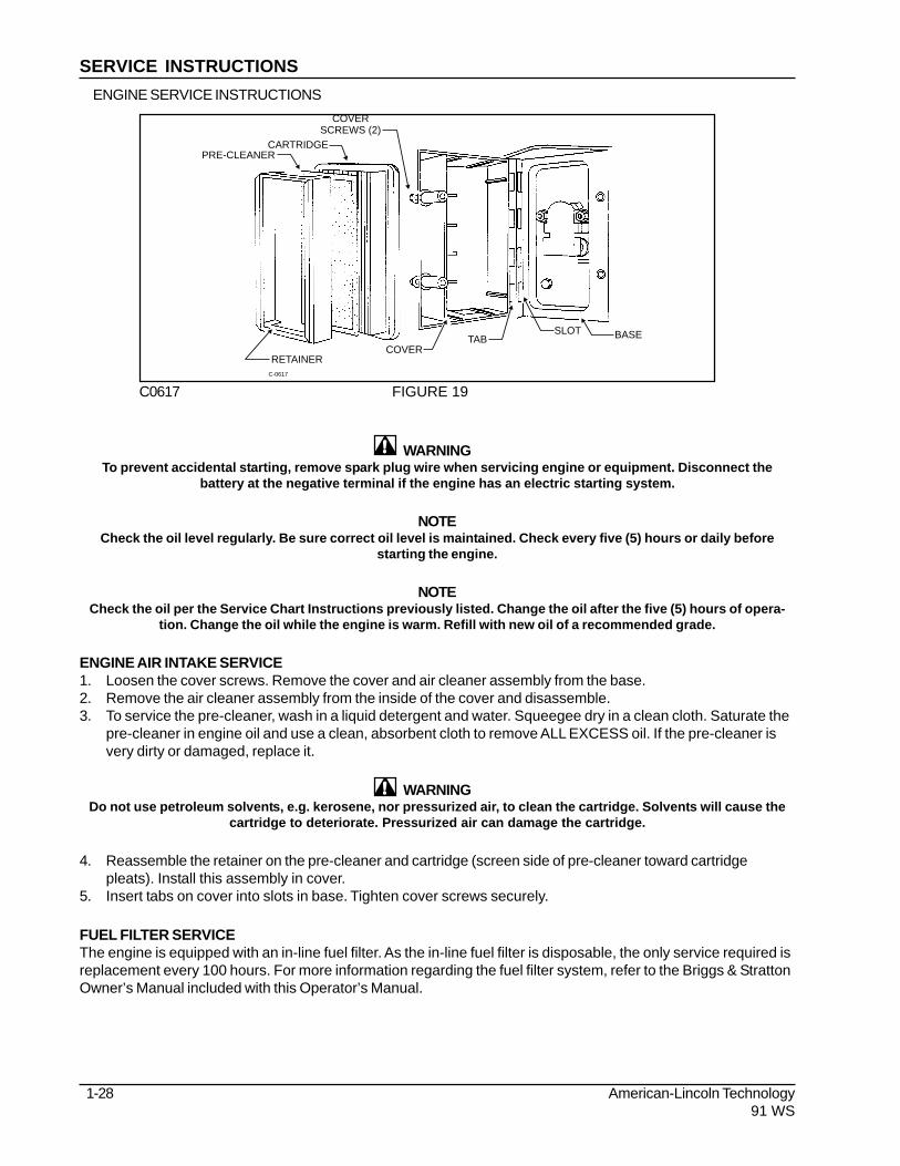
ENGINE AIR INTAKE SERVICE1. Loosen the cover screws. Remove the cover and air cleaner assembly from the base.2. Remove the air cleaner assembly from the inside of the cover and disassemble.3. To service the pre-cleaner, wash in a liquid detergent and water. Squeegee dry in a clean cloth. Saturate the
pre-cleaner in engine oil and use a clean, absorbent cloth to remove ALL EXCESS oil. If the pre-cleaner isvery dirty or damaged, replace it.
WARNINGDo not use petroleum solvents, e.g. kerosene, nor pressurized air, to clean the cartridge. Solvents will cause the
cartridge to deteriorate. Pressurized air can damage the cartridge.
4. Reassemble the retainer on the pre-cleaner and cartridge (screen side of pre-cleaner toward cartridgepleats). Install this assembly in cover.
5. Insert tabs on cover into slots in base. Tighten cover screws securely.
FUEL FILTER SERVICEThe engine is equipped with an in-line fuel filter. As the in-line fuel filter is disposable, the only service required isreplacement every 100 hours. For more information regarding the fuel filter system, refer to the Briggs & StrattonOwner’s Manual included with this Operator’s Manual.
PRE-CLEANER
RETAINERC-0617
COVERTAB
SLOT BASE
CARTRIDGE
COVERSCREWS (2)
C0617 FIGURE 19
SERVICE INSTRUCTIONSENGINE SERVICE INSTRUCTIONS

American-Lincoln Technology 1 - 2991 WS
TO CHECK THE ENGINE OIL LEVELBe sure the correct engine oil level is maintainedby checking the oil level daily. Use the dipstick toverify the correct oil level and add oil as indicatedon the dipstick. When changing the oil you mustfirst remove the drain plug which is located on therear of the engine. Refer to the Briggs & StrattonEngine Owners’ Manual for more information onrecommended type and grade of oil to be used.
DRIVE SYSTEM SERVICE INSTRUCTIONSTO ADJUST THE NEUTRAL SETTINGThe only item that should have to be moved is the linkage rod itself. By adjusting the clevisis in or out, oneshould be able to achieve neutral when you install the new belt or if the machine begins to creep.
TO REPLACE THE FORWARD DRIVE BELT1. Remove the two (2) inspection plugs on the right hand side of the machine which allows access to the
bearing plate on the end of the differential.2. Reach in through the inspection holes and remove the two (2) bolts that hold the differential bearing plate in.
Remove and retain hardware.3. Loosen the chain idler pulley and move it to the top of the slot to relax all tension on the chain. Retighten
the idler.4. Remove the drive wheel chain by walking it off the differential. With the idler out of the way, it should all you
plenty of clearance to come off the end of the differential.5. Move the bearing plate in an upward position to give you clearance for installing the new belt.6. Begin by working the forward drive belt around the bearing plate. Once this is around the bearing plate, the
reverse belt off the differential shieve and leave it lay off to the left hand side of the shieve.7. Take the main forward belt and work it back around the forward idler underneath the main drive shieve and
around the rear of the forward and reverse idler pulley and up over the forward and reverse idler pulley.8. When installing the forward drive belt, one side of the belt is printed and says “This Side Out”. On the
forward drive belt, you want to have that so you cannot read it when it is installed. It will be riding againstthe shieve itself on the differential because the machine is driven off the backside of that belt.
9. Once that main forward drive belt is installed and routed correctly, reattach the reverse belt the same way itwas routed before.
10. At the front of the machine, refasten the bearing plate on the end of the differential to the frame.11. Start you chain back around the differential and readjust the idler for the drive chain.12. Any fine adjustments for neutral that need to be done should be done with the linkage rod only.
C06241
C0624A FIGURE 20
SERVICE INSTRUCTIONS

1-30 American-Lincoln Technology91 WS
SERVICE INSTRUCTIONS
DRIVE SYSTEM SERVICE INSTRUCTIONS - Cont.TO REPLACE THE REVERSE BELT1. Remove the two (2) inspection plugs on the right hand side of the machine which allows access to the
bearing plate on the differential shaft. Loosen and remove both bolts holding the bearing plate to themachine.
2. Loosen the drive wheel chain idler and pull it to the top of the slot. Retighten it to keep it out of the way.This allows you freedom to walk the chain off the differential.
3. At the rear of the machine, follow the main broom belt down to the idler. Disconnect the spring to releasethe tension on that belt and remove the right hand side broom belt.
4. Remove the main broom belt.5. At the front of the machine, place the differential plate with the bearing in it to the “UP” position. This allows
you clearance to feed the new belt in.6. If the forward belt is still in good condition, you will need to start by removing it off the main drive shieve off
the differential.7. Get both the forward and reverse belt off the differential shieve laying them to the left hand side.8. Work the reverse belt over the differential shieve once you are on the front and off to the left hand side of the
shieve with both belts hanging loose around the differential.9. Take the top portion of the belt and pick it up and the bottom portion of the belt and bring it to the “UP”
position. That will need to be worked around the main shieve coming off the motor in between the shieveand the fixed bracket that holds the forward idler pulley. This clearance is very tight and you must be carefulnot to cut the belt while you are working around that.
10. Work the belt around the forward and reverse main idler by putting it back over top of it.11. Come back to the front of the machine and lower the differential bearing plate.12. Reinstall the 2 bolts in that and reset the chain idler back to its position and retighten.13. Move to the rear of the machine again and reinstall the main drive broom belt and the spring that was taken
off the right hand side broom belt.14. Any fine adjustments should be able to be done with the linkage rod itself.

American-Lincoln Technology 1 - 3191 WS
LP SAFETY PRECAUTIONS
WARNINGKeep cigarettes, sparks, and open flame away when working on LP equipment when inspecting for gas leaks or
when LP tanks are present.
WARNINGCheck all components for proper operation when needed. Replace LP components when needed. Never bypass
defective safety components.
WARNINGCheck routing of all LP hoses. Keep them away from sharp edges, exhaust manifolds, or other hot surfaces.
Check for signs of abrasion or deterioration.
WARNINGCheck for gas odor before and during starting operations. If gas odor is noticed, stop and check for leaks or
component malfunction.
WARNINGMake sure LP tank is free of dents and gouges.
WARNINGMake sure service coupling is clean and free of damage. Make sure service coupling of tank matches machine
service coupling.
WARNINGKeep engine properly tuned.
WARNINGMake sure the LP tank matches the fuel system.
WARNINGMake sure the LP tank is securely mounted on the machine with the retainer bracket clamping the tank with the
locating pin in position.
WARNINGPark the machine in a shaded, cool area when not in use.
WARNINGKeep the LP tank service valve closed when the tank is not in use.
WARNINGNever overfill the LP tank. Fill the LP tank to the recommended weight stamped on the tank.
WARNINGUse care in handling LP tanks. Never drag or drop them.
WARNINGAlways store and transport LP fuel tanks with the safety relief valve in the “UP” position.
WARNINGAvoid contact with the LP fuel to avoid frostbite.
WARNINGWhen the machine is to stand unused for a period of time (overnight), park the machine in a designated area. Shutoff the service valve at the tank and operate the engine until the remaining fuel is consumed. Turn off the ignition
switch.
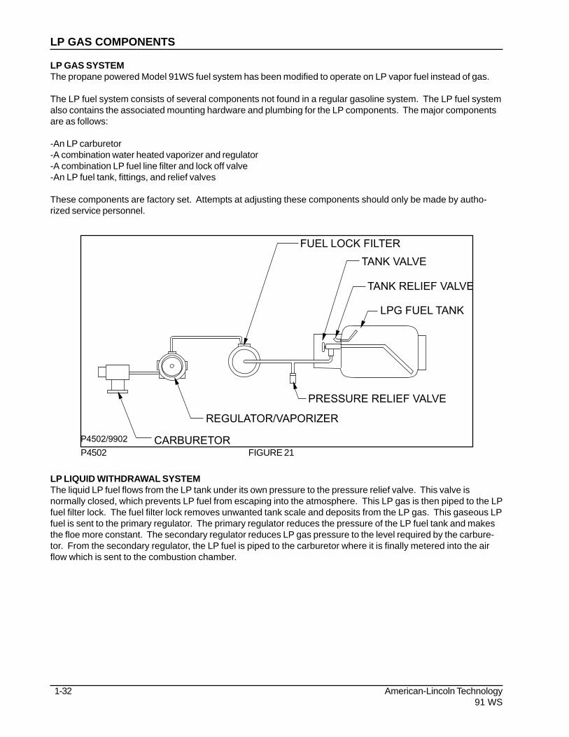
1-32 American-Lincoln Technology91 WS
LP GAS COMPONENTS
FUEL LOCK FILTER
TANK VALVE
TANK RELIEF VALVE
LPG FUEL TANK
PRESSURE RELIEF VALVE
REGULATOR/VAPORIZER
CARBURETORP4502/9902
P4502 FIGURE 21
LP GAS SYSTEMThe propane powered Model 91WS fuel system has been modified to operate on LP vapor fuel instead of gas.
The LP fuel system consists of several components not found in a regular gasoline system. The LP fuel systemalso contains the associated mounting hardware and plumbing for the LP components. The major componentsare as follows:
-An LP carburetor-A combination water heated vaporizer and regulator-A combination LP fuel line filter and lock off valve-An LP fuel tank, fittings, and relief valves
These components are factory set. Attempts at adjusting these components should only be made by autho-rized service personnel.
LP LIQUID WITHDRAWAL SYSTEMThe liquid LP fuel flows from the LP tank under its own pressure to the pressure relief valve. This valve isnormally closed, which prevents LP fuel from escaping into the atmosphere. This LP gas is then piped to the LPfuel filter lock. The fuel filter lock removes unwanted tank scale and deposits from the LP gas. This gaseous LPfuel is sent to the primary regulator. The primary regulator reduces the pressure of the LP fuel tank and makesthe floe more constant. The secondary regulator reduces LP gas pressure to the level required by the carbure-tor. From the secondary regulator, the LP fuel is piped to the carburetor where it is finally metered into the airflow which is sent to the combustion chamber.

American-Lincoln Technology 1 - 3391 WS
LP GAS COMPONENTS
LPG INLETHAND PRIMER PIN
PLUGVAPOROUTLET
P-4563A
WATER
MOUNTING HOLES
P4563 FIGURE 22
LP CHECKLISTThis checklist can be preformed quickly and should be done before every use. Be sure to make all necessarychecks as listed on the Maintenance Chart as discussed earlier.
1. Check for connections for leaks.2. Open the LP storage tank valve.3. Check the regulator. Momentarily press the fuel primer on the regulator cover to bleed air out of the system.4. Start the machine’s engine.
LP FUEL TANKSStandard D.O.T. LP fuel tank sizes have 14, 20, 33.5, and 43.5 pounds capacities. The liquid volume permittedin these containers is less than the total volume of the cylinder. This provides for expansion of the LP fuelshould the temperature increase above the normal amounts. Excessive heat may cause the fuel to expand toomuch causing the safety relief valve to vent some LP fuel, relieving internal tank pressure.
Each tank is marked showing the type of construction (liquid or vapor), the manufacturer, the date of manufac-ture, the capacity, the weight, and the date of requalification. D.O.T. fuel tanks must be requalified (checked)periodically, This requalification must be recorded and maintained for the life of the container.
LP fuel tanks are equipped with the following approved values and fittings:
Safety Relief Valve - This is a spring loaded valve that relieves excessive pressures which may develop in thetank due to unusual condition.
Liquid Service Valve - Liquid is withdrawn from the tank through this valve. The LP tank may be filled though thisvalve if the tank in not equipped with a filter valve.
Excessive Flow Valve - This valve is part of the Liquid Service Valve. It is mounted inside the tank and preventsLP fuel from leaving the LP tank in the event of accidental breakage of external fittings or hoses. It permitsflow in either direction but stops outward flow if that flow becomes excessive.
Filter Valve - This valve is optional. If this valve is not present, the tank is filled through the service valve.Liquid Level Gauge - This gauge is optional.

1-34 American-Lincoln Technology91 WS
LP TANK CARE
USE AND CARE OF LP TANKSIf an LP tank is damaged or leaking, it should be immediately removed to a designated safe area and the properpersonnel should be notifies. Do not attempt to make repairs to the cylinder regardless of its condition. Repairsmust be made by qualified personnel.
The care an LP tank receives has a direct bearing on how long the tank can be used safely. LP tanks must notbe dropped, dragged, or slid across any surface. To move the LP tank, use a hand truck or roll the tank on itsfoot ring while it is being held in a position slightly off the vertical.
CHANGING LP TANKSRefueling machines with LP tanks is an important process. Refueling is accomplished by replacing the emptyLP tank with a full one.
The tank changing operation presents an opportunity for the machine operator to carefully inspect the tank, tankfittings, the fuel lines, and fuel line fittings. If abnormal wear is detected, the operator should report thesefindings to the appropriate personnel for immediate action.
TO BEGIN CHANGING THE LP TANK1. Park the machine in a designated safe area and set the parking brake.2. Close the tank valve.3. Remove the quick disconnect coupling from the tank valve.4. Inspect the machine’s fuel lines and the quick disconnect coupling for damaged or abnormal wear.5. Remove the empty tank from the holding device.6. Inspect the tank and tank fittings for damage and abnormal wear. Handle the tank carefully. It must nor be
dropped or mishandled.7. Store the LP tank in a designated safe area.8. Select a filled LP tank and observe for damage or leaks.9. Carefully install the filled tank in the machine so that the tank centering pin enters the aligning hole (closest
to the tank) in the tank collar. This assures that the tank is positioned properly and allows for properoperation of the safety relief valve, liquid level gauge, and service valves.
10. Fasten the tank retaining bracket so that the tank is locked into position.11. Reconnect the fuel line to the tank servicing coupling.12. Open the service valve slowly and check for leaks. If a leak is found, close the valve immediately and notify
the appropriate personnel.13. If no leaks are detected, the engine is ready to start. Do not start the engine unless the operator is inposition with the directional control pedal in the neutral position.
STORAGE OF LP FUEL TANKSWhether the storage is inside or outside, the LP tanks should not be in the vicinity of combustible materials orhigh temperature sources such as ovens or furnaces. This may cause the heat to raise the pressure of the fuelto a point where the safety valves would begin to operate. Care should be taken to ensure that the cylinders arestored in such a manner that if the safety relief valves are triggered, the vapor will be relieved rather than anyliquid.
Valves on empty tanks must be closed during storage and transportation.
Similar precautions should be taken in storing machines fitted with LP tanks. They may be stored or servicedinside buildings provided there are no leaks in the fuel system and the tanks have not been overfilled. If ma-chines are being repaired inside a building, the shutoff valve on the tanks must be closed except when theengine must be on during servicing.

American-Lincoln Technology 1 - 3591 WS
STANDARD METRIC TORQUE VALUES
When tightening torques are not specified, tighten the bolts and nuts according to the table below.
GRADE No-Grade or 4T 7T 9T
SS41, S20C S43C, S48C SCR435, SCM435
Nom. Unit N.m kgf.m ft-lbs N.m kgf.m ft-lbs N.m kgf.m ft-lbs
Dia.
M6 7.85 0.80 5.79 9.81 1.00 7.23 12.26 1.25 9.04
(6mm, 0.24 in.) to to to to to to to to to
9.32 0.95 6.87 11.28 1.15 8.32 14.22 1.45 10.49
M8 17.7 1.8 13.0 23.5 2.4 17.4 29.4 3.9 21.7
8mm, 0.31 in.) to to to to to to to to to
20.6 2.1 15.2 27.5 2.8 20.3 34.3 3.5 25.3
M10 39.2 4.0 28.9 48.1 4.9 35.4 60.8 6.2 44.8
(10mm, 0.39 in.) to to to to to to to to to
45.1 4.6 33.3 55.9 5.7 41.2 70.6 7.2 52.1
M12 62.8 6.4 46.3 77.5 7.9 57.1 103.0 10.5 75.9
(12mm, 0.47 in.) to to to to to to to to to
72.6 7.4 53.5 90.2 9.2 66.5 117.7 12.0 86.8
ENGINE TORQUE VALUES
Screws, bolts and nuts must be tightened to the specified torque using a torque wrench. Several
screws, bolts, and nuts such as those used on the cylinder head must be tightened in proper
sequence and at the proper torque.
ITEM Size & Pitch N.m kgf.m ft-lbs
*Head Cover Cap Nuts M6 x 1.0 3.9 to 5.9 0.4 to 0.6 2.9 to 4.3
*Head Bolts M8 x 1.25 37.2 to 42.1 3.8 to 4.3 28.9 to 32.5
*Bearing Case Bolts 1 M6 x 1.0 12.7 to 15.7 1.3 to 1.6 9.4 to 11.6
*Bearing Case Bolts 2 M7 x 1.0 26.5 to 30.4 2.7 to 3.1 19.6 to 22.5
*Flywheel Bolts M10 x 1.25 53.9 to 58.8 5.5 to 6.0 39.8 to 43.4
*Connecting Rod Bolts M6 x 0.75 26.5 to 30.4 2.7 to 3.1 10.8 to 13.7
*Rocker Arm Bracket Bolts M6 x 1.0 9.81 to 11.28 1.00 to 1.15 7.23 to 8.32
*Idler Gear Shaft Bolts M6 x 1.0 9.81 to 11.28 1.00 to 1.15 7.23 to 8.32
Spark Plugs M14 x 1.25 19.6 to 24.5 2.0 to 2.5 14.5 to 18.1
Drain Plugs M12 x 1.25 32.4 to 37.3 3.3 to 3.8 23.9 to 27.5
Oil Switch Taper Bolt PT 1/8 14.7 to 19.6 1.5 to 2.0 10.8 to 14.5
*Crankshaft Bolt M12 x 1.5 98.1 to 107.9 10.0 to 11.0 72.3 to 79.6
For "*" marked bolts and nuts in the table, apply engine oil to their threads and seats before
tightening.
Screw and bolt material grades are shown by numbers punched on the screw and bolt heads.
C-2005
STANDARD HARDWARE & TORQUE VALUES

1-36 American-Lincoln Technology91 WS
FRACTION FRACTIONDECIMAL DECIMALMILLIMETER MILLIMETER
C-2001/9907
DECIMAL METRIC & CONVERSION TABLE

American-Lincoln Technology 1 - 3791 WS
SAE - Grade 5 SAE - Grade 8
ScrewSize
Grade5
Plated
Grade8
Plated
410HStainless
BrassTypeF & T& BT
TypeB, AB
*6
*8
*10
*1/4
5/16
3/8
7/16
1/2
9/16
5/8
3/4
7/8
1
14
27
39
86
15
28
44
68
98
135
239
387
579
15
28
43
108
17
31
49
76
110
153
267
-
-
-
-
-
130
22
40
63
95
138
191
338
545
818
-
-
-
151
24
44
70
108
155
216
378
-
-
18
33
47
114
19
34
55
85
-
-
-
-
-
20
35
54
132
22
39
62
95
-
-
-
-
-
5
9
13
32
6
10
16
-
-
-
-
-
-
20
37
49
120
-
-
-
-
-
-
-
-
-
23
41
64
156
-
-
-
-
-
-
-
-
-
21
34
49
120
-
-
-
-
-
-
-
-
-
CC C CF F F F
C = Coarse ThreadF = Fine Thread* = Torque values for #6 through 1/4 are lb./in. All others are lb./ft.
NOTE
Decrease the torque by 20% when using thread lubricantThe torque tolerance is ± on torque values.
C2000/9905
BOLT IDENTIFICATION

1-38 American-Lincoln Technology91 WS
ABBREVIATIONS - SCREWS
ADJ = Adjusting Screw
ADJ.SP = Adjusting Plunger Screw
BHM = Binding Head Machine Screw
BHS = Button Head Socket Screw
CAPT.SL = Captivated Slotted Screw
CAPT.WG = Captivated Wing Screw
FHM = Flat Head Machine Screw
FIL.HM = Filister Head Machine Screw
HHC = Hexagon Head Cap Screw
HHM = Hexagon Head Machine Screw
HIHD = 1/2 High Head Screw
HSHC = Hexagonal Socket Head Cap Screw
HSFHC = Hexagonal Socket Flat Head Cap Screw
KNH = Knurled Head Screw
MHHC = Metric Hexagon Head Cap Screw
PHM = Pan Head Machine Screw
RHD = Round Head Drive Screw
RHM = Round Head Machine Screw
RHW = Round Head Wood Screw
SHC = Shiny Crown Cap Screw
SHTB = Shoulder Thumb Screw
SQ = Square Head Screw
TB = Thumb Screw
THM = Truss Head Machine Screw
WELD = Weld Stud
WG = Wing Screw
ABBREVIATIONS - SETSCREWS
HS = Hexagonal Socket Setscrew
S = Slotted Setscrew
SH = Square Head Setscrew
-KCP = Knurled Cup Point Setscrew
-CP = Cup Point Setscrew
-OP = Oval Point Setscrew
-FDP = Full Dog Point Setscrew
-HDP = Half Dog Point Setscrew
-FP = Flat Point Setscrew
-COP = Cone Point Setscrew
C-2004
LEGEND - SCREWS/ SETSCREWS

American-Lincoln Technology 1 - 3991 WS
Key No. Part Number DescriptionH1 2-00-05060 Screw, #6-32 x 1.250 RHMH2 2-00-00455 Flat Washer, .375 x .156 x .047H3 2-00-01499 Lock Washer, #6 Med. Helical SpringH4 2-00-00624 Nut, #6-32 HexH5 2-00-00645 Nut, Hex Fiber Insert #6-32H6 2-00-00049 Screw, # 10-24 x .500 RHMH7 2-00-00056 Screw, # 10-24 x .750 RHMH8 2-00-00039 Screw, 10-24 x 1.000 RHMH9 2-00-00426 Flat Washer, .500 x .219 x .063H10 2-00-00519 Lock Washer, # 10 Med HSH11 2-00-00605 Nut, Hex MS # 10-24 x .375 x .125H12 2-00-01246 Nut, Hex Fiber Insert #10-24H13 2-00-00054 Screw, 1/4-20 x .500 RHMH14 2-00-00219 Screw, 1/4-20 x .500 HHCH15 2-00-00221 Screw, 1/4-20 x .750 HHCH16 2-00-03051 Screw, 1/4-20 x .750 HSHCH17 2-00-00205 Screw, 1/4-20 x 1.000 HHCH18 2-00-00060 Screw, 1/4-20 x 1.250 RHMH19 2-00-02587 Screw, 1/4-20 x 1.250 HHCH20 2-00-00203 Screw, 1/4-20 x 1.500 HHCH21 2-00-01769 Screw, 1/4-20 x 1.750 HHCH22 2-00-02589 Screw, 1/4-20 x 2.000 HHCH23 2-00-01980 Screw, 1/4-20 x 2.500 HHCH24 2-00-00220 Screw, 1/4-20 x .625 HHCH25 2-00-00594 Nut, Hex 1/4-20 x .437 x .218H26 2-00-00641 Nut, 1/4-20 Insert FiberH27 2-00-03702 Washer, .625 x .281 x .063H28 2-00-04685 Screw, 1/4-20 x .750 HHCH29 2-00-04966 Screw, 1/4-20 x 1.500 HHMH30 2-00-04687 Lock Washer, Hel. Spring 1/4 Med.H31 2-00-04695 Screw, # 10-32 x .630 RHMH32 2-00-04688 Nut, 1/4-20 Hex.H33 2-00-00224 Screw, 5/16-18 x .500 HHCH34 2-00-00208 Screw, 5/16-18 x .750 HHCH35 2-00-02708 Screw, 5/16-18 x 1.000 HHMH36 2-00-00196 Carriage Bolt, 5/16-18 x 1.000H37 2-00-00207 Screw, 5/16-18 x 1.250 HHCH38 2-00-00225 Screw, 5/16-18 x 1.500 HHCH39 2-00-00218 Screw, 5/16-18 x 2.000 HHCH40 2-00-01770 Screw, 5/16-18 x 2.750 HHCH41 2-00-02597 Screw, 5/16-18 x 3.250 HHCH42 2-00-02655 Screw, 5/16-18 x 4.500 HHCH43 2-00-00409 Flat Washer, .687 x .344 x .062H44 2-00-00530 Lock Washer, 5/16 HS Med.H45 2-00-00585 Nut, Hex. 5/16-18 x .500 x .265H46 2-00-00644 Nut, 5/16-18, Insert FiberH47 2-00-00232 Screw, 3/8-16 x .750 HHCH48 2-00-00233 Screw, 3/8-16 x 1.000 HHCH49 2-00-00209 Screw, 3/8-16 x 1.250 HHCH50 2-00-00234 Screw, 3/8-16 x 1.500 HHCH51 2-00-00216 Screw, 3/8-16 x 2.000 HHCH52 2-00-00402 Flat Washer, .750 x .390 x .094H53 2-00-02310 Lock Washer, Helical Spring 3/8H54 2-00-02360 Nut, 3/8-16 Hex.H55 2-00-00643 Nut, 3/8-16 StopH56 2-00-00239 Screw, 1/2-13 x 1.000 HHCH57 2-00-00240 Screw, 1/2-13 x 1.250 HHCH58 2-00-00241 Screw, 1/2-13 x 1.750 HHCH59 2-00-00242 Screw, 1/2-13 x 2.250 HHCH60 2-00-02682 Screw, 1/2-13 x 2.750 HHCH61 2-00-02616 Screw, 1/2-13 x 3.000 HHCH62 2-00-00405 Flat Washer, 1.063 x .531 x .094
HARDWARE LEGEND

1-40 American-Lincoln Technology91 WS
Key No. Part Number DescriptionH63 2-00-02312 Lock Washer, 1/2 HS Med.H64 2-00-00596 Nut, Hex. 1/2-13 x .750 x .437H65 2-00-04936 Nut, 1/2-13 Fibre LockH66 2-00-02689 Screw, 1/2-20 x 1.000 HHCH67 2-00-00614 Nut, Hex 1/2-20H68 2-00-00640 Nut, Hex Fiber Insert 1/2-20H69 2-00-01255 Screw, 5/16-18 x .875 HHCH70 2-00-05254 Screw, 3/4-10 x 2.250 HHCH71 2-00-05255 Nut, 3/4-10 Nylon LockH72 2-00-00518 Lock Washer, Helical SpringH73 2-00-00247 Screw, 1/2-13 x 2.500 HHCH74 2-00-03170 Flat Washer, 1.500 x .750 x .125H75 2-00-00618 Nut, Hex Jam 3/8-16H76 2-00-00632 Nut, Fiber Insert 3/8-24 SteelH77 2-00-00484 Flat Washer, .625 x .375 x .046H78 2-00-05187 Carriage Bolt, 3/8-16 x 1.250H79 2-00-01676 Flat Washer, 1.062 x .265 x .062'H80 2-00-02196 Carriage Bolt, 1/4-20 x 1.000 RHMH81 2-00-05276 Screw, 3/8-16 x 5.500H82 2-00-00505 Lock Washer, 3/8 Int. ToothH83 2-00-04877 Screw, 1/4-20 x 1.000 BHSH84 2-00-00228 Screw, 5/16-18 x 2.250 HHCH85 2-00-00650 Nut, Cap 3/8-16 Low CrownH86 2-00-03575 Carriage Bolt, 1/4-20 x .750H87 2-00-00263 Set Screw, 1/4-20 x .250 HSKCPH88 2-00-05258 Screw, #8-325 x .750 BHSH89 2-00-01372 Nut, Fiber Insert #8-32 SteelH90 2-00-03569 Carriage Bolt, 5/16-18 x .750H91 2-00-05279 Screw, M6 x 1.0 x 20 mm MHHCH92 2-00-04801 Flat Washer, .875 x .375 x .125H93 2-00-00222 Screw, 1/4-20 x 1.250 HHMH94 2-00-00410 Flat Washer, .875 x .375 x .060H95 2-00-03382 Spring Washer, .875 x .500 x .015H96 2-00-02605 Screw, 3/8-16 x 4.500 HHCH97 2-00-04677 Screw, 1/4-20 x .750 HSCH98 2-00-05277 Screw, 1/2-13 x .750 HSHCH99 2-00-02810 Screw. 1/4-20 x 1.000 FHMH100 2-00-03062 Screw, #10-24 x .625 THMH101 2-00-04897 Screw, #10-24 x 1.250 THMH102 2-00-04795 Screw, #10-24 x .750 BHSH103 2-00-00089 Screw, 10-24 x 1.500 RHMH104 2-00-03541 Screw, 1/4-20 x 1.500 FHSCHH105 2-00-05260 Nut, Jam #8-32H106 2-00-04886 Screw, 3/8-16 x .500 HSHCH107 2-00-04887 Screw, Main Broom ControlH108 2-00-04888 Washer, Main Broom ControlH109 2-00-00522 Lock Washer, 3/4 Helical SpringH110 2-00-03039 Screw, 1/4-20 x .625 HSHCH111 2-00-03296 Screw, 3/8-16 x 4.000 HHCH112 2-00-02603 Screw, 3/8-16 x 3.500 HHCH113 2-00-03333 Screw, 3/8-16 x 3.750 HHCH114 2-00-00633 Nut, Fiber 1/4-28H115 2-00-03063 Screw, #10-24 x .750 THMH116 2-00-01951 Carriage Bolt, 1/4-20 x 1.250H117 2-00-05067 Flat Washer, 1.750 x .531 x .100H118 2-00-02618 Screw, 1/2-13 x 3.500 HHCH119 2-00-05005 Screw, M10 x 1.500 30 mm MHHCH120 2-00-03829 Lock Washer, 3/8 BoltH121 2-00-00090 Screw, #8-32 x 1.500 RHMH122 2-00-05216 Screw, 1/4-20 x 5.000 HHCH123 2-00-00204 Screw, 1/4-20 x 1.500 HHCH124 2-00-02296 Lock Washer, #10 Ext. Shakeproof
HARDWARE LEGEND
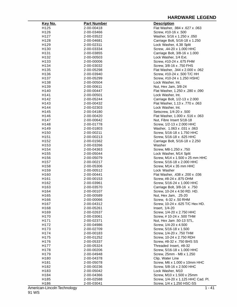
American-Lincoln Technology 1 - 4191 WS
H125 2-00-00418 Flat Washer, .984 x .627 x .063H126 2-00-03466 Screw, #10-16 x .500H127 2-00-03522 Washer, 5/16 x 1.250 x .050H128 2-00-04681 Carriage Bolt, 5/16-18 x 1.250H129 2-00-02311 Lock Washer, 4.38 SplitH130 2-00-03334 Screw, .44-20 x 1.000 HHCH131 2-00-03855 Carriage Bolt, 3/8-16 x 1.000H132 2-00-00503 Lock Washer, 1/4 Ext.H133 2-00-00006 Screw, #10-24 x .675 FHMH134 2-00-03032 Screw, 3/8-16 x .750 FHSH135 2-00-05298 Flat Washer, .344 x 2.000 x .062H136 2-00-03940 Screw, #10-24 x .500 T/C HHH137 2-00-05299 Screw, #10-24 x 1.250 HSHCH138 2-00-00504 Lock Washer, Int.H139 2-00-00611 Nut, Hex Jam, 3/8-24H140 2-00-00447 Flat Washer, 1.250 x .280 x .090H141 2-00-00501 Lock Washer, Int.H142 2-00-05244 Carriage Bolt, 1/2-13 x 2.000H143 2-00-00432 Flat Washer, 1.13 x .770 x .063H144 2-00-02303 Lock Washer, Int.H145 2-00-04180 Setscrew, 1/4-20 x .500H146 2-00-00420 Flat Washer, 1.000 x .516 x .063H147 2-00-00642 Nut, Fibre Insert 5/18-18H148 2-00-01778 Screw, 1/2-13 x 2.000 HHCH149 2-00-01803 Washer, 1.063 x .031 x .063H150 2-00-00211 Screw, 5/16-18 x 1.750 HHCH151 2-00-00213 Screw, 5/16-18 x .625 HHCH152 2-00-01562 Carriage Bolt, 5/16-18 x 2.250H153 2-00-03266 WasherH154 2-00-04363 Screw, M8-1.250 x .750H155 2-00-05044 Lock Washer, M14 SplitH156 2-00-05079 Screw, M14 x 1.500 x 25 mm HHCH157 2-00-00217 Screw, 5/16-18 x 2.000 HHCH158 2-00-05306 Screw, M14 x 35 mm HHCH159 2-00-00512 Lock WasherH160 2-00-00441 Flat Washer, .438 x .200 x .036H161 2-00-00153 Screw, #8-24 x .875 OHMH162 2-00-03961 Screw, 5/16-24 x 1.000 HHCH163 2-00-03570 Carriage Bolt, 3/8-16 x .750H164 2-00-00107 Screw, 10-24 x 4.50 RD. HD.H165 2-00-00589 Nut, Hex Jam, .25-20H166 2-00-00066 Screw, 6-32 x .50 RHMH167 2-00-04312 Screw, 10-24 x .625 T/C Hex HD.H168 2-00-05261 Insert, 1/4-20H169 2-00-02637 Screw, 1/4-20 x 2.750 HHCH170 2-00-03061 Screw, # 10-24 x .500 THMH171 2-00-02371 Nut, Hex Jam .50-13 STL.H172 2-00-04986 Screw, 1/4-20 x 4.500H173 2-00-02709 Screw, 5/16-18 x 1.500H174 2-00-00183 Screw, 1/4-20 x .750 THMH175 2-00-01252 Screw, 10-24 x 2.750 RDHH176 2-00-05337 Screw, #8-32 x .750 BHS SSH177 2-00-05324 Threaded Insert, #8-32H178 2-00-00206 Screw, 5/16-18 x 1.000 HHCH179 2-00-04948 Screw, 25mm - M8 x 1.250H180 2-00-04378 Clip, Water LineH181 2-00-05078 Screw, M6 x 1.000 x 10mm HHCH182 2-00-00236 Screw, 5/8-16 x 2.500 HHCH183 2-00-05042 Lock Washer, M10H184 2-00-04366 Screw, M10 x 1.500 x 25mmH185 2-00-02588 Screw, 1/4-20 x 1.125 HHC Cad. Pl.H186 2-00-03041 Screw, 1/4 x 1.250 HSC-SS
Key No. Part Number DescriptionHARDWARE LEGEND

1-42 American-Lincoln Technology91 WS
Key No. Part Number DescriptionH187 2-00-00071 Screw, #10-24 x 1.250 RHMH188 2-00-01987 Flat Washer, .438 x .200 x .036 sstH189 2-00-00460 Flat Washer, .437 x .192 x .031-sH190 2-00-00529 Lock Washer - helical sps, 8 MDMH191 2-00-00602 Nut, MSCR - Hex, 8-32H192 2-00-04841 Nut 3/4 - 16 Slotted Hex headH193 2-00-03412 Lock Nut, .375 - 24, sps 21 FKH194 2-00-03537 Screw - 1/4 - 20 x2.000H195 2-00-04210 ClampH196 2-00-05350 Screw 1/4 - 28 x .63 HHCH197 2-00-03979 Washer 1.00 x .391 x .06H198 2-00-03808 Wahser 1.50 x .750 x .06H199 2-00-04603 ClampH200 2-00-00626 Nut, Hex MS #10 - 32 x .375 x .125H201 2-00-02011 Plastic Plug, .440 Dia (Diesel)H202 2-00-04514 Plastic Plug, .562 Dia ( LP & Gas)H203 2-00-04794 Screw, #10 - 24 x .625 BHSH204 2-00-04873 ClampH205 2-00-04721 Grommet, 1.750 x1.125 x .500 x.125H206 2-00-00407 Washer, Flat .562 x.265H207 2-00-02227 Key, .125 x .750 SQH208 2-00-00772 Cotterpin .093 x 1.000H209 2-00-00586 Nut Hex Jam 5/16 - 18x .500 x .187H210 2-00-00776 Cotterpin .125x1.500H211 2-00-02728 Screw 10 - 32 x .375 BHMH212 2-00-00566 Fitting-GreaseH213 2-00-01254 Screw - 1/2 - 13 x 1.500 HHCSH214 2-00-00462 Flat Washer, .562 x .250 x .031H215 2-00-02558 Grease ZerkH216 2-00-04378 Harness ClampH217 2-00-00511 Internal Washer, #6H218 2-00-05345 Screw, Hex Head CapH219 2-00-05359 Nut, Serrated Flange 5/16-18H220 2-00-02617 Screw, 50-13 x 3.25 HHCH221 2-00-03335 Screw, Hex SOC Cap, .312 -18 x .50H222 2-00-02848 Screw, 10-32 x .50 Cad PL,STL RHMH223 2-00-00631 Nut, .31 - 24 Fiber InsertH218 2-00-05345 Screw, Hex Head CapH219 2-00-05359 Nut, Serrated Flange 5/16-18H220 2-00-02617 Screw, 50-13 x 3.25 HHCH221 2-00-03335 Screw, Hex SOC Cap, .312 -18 x .50H222 2-00-02848 Screw, 10-32 x .50 Cad PL,STL RHMH223 2-00-00631 Nut, .31 - 24 Fiber InsertH224 2-00-04686 Lock Washer-helical#10Scr.Med. SSH225 2-00-04851 Washer, Engine MountH226 2-00-04689 Washer, 11/16 OD x .260 ID x .050H227 2-00-04596 Screw, Hex Head 1/4 - 20 x 3.5H228 2-00-02606 Screw, .375 - 24 x 1.00, STL HHCH229 2-00-01490 Screw, .25 - 20 x .875 HHC STLH230 2-00-00466 Flat Washer, .625 x .203 x .031H231 2-00-02933 Screw, Mach 10 - 24 x 3.50H232 2-00-04909 Yoke, Pin Assy.H233 2-00-02638 Screw, HHC .25-20 x 3.00H234 2-00-00064 Screw- RHM #10-24 x .88H235 2-00-00197 Carriage Bolt, .38-16 x 2.75H236 2-00-02369 Nut, Hex Jam, .38-16H237 2-00-05356 Screw, 5/16 - 18 X 1.25 Grade 8H238 2-00-03750 Carriage Bolt, .38-16 x 1.50H239 2-00-02814 Screw-FHM .25-20x1.75H240 2-00-05398 Screw, HSHC 3/8-16 x .50H241 2-00-05395 Screw, RHM .25-20 x 4.00 ZincH242 2-00-05370 Screw, M12 - 16 x 1.75 x 40mm HHC
HARDWARE LEGEND

American-Lincoln Technology 1 - 4391 WS
H243 2-00-00591 Nut, Hex-Jam .50-20H244 2-00-05297 Nut, Insert Fiber, .38-16 Heavy NutH245 2-00-05401 Shoulder Screw, 1/2-3/4H246 2-00-05122 Screw-HHC, .25-20 x 2.00H247 2-00-04590 WasherH248 2-00-05236 Flat Washer, 2.000 x .281 x .063H249 2-00-00004 Screw-FHM #10-24 x 1.25H250 2-00-04968 Screw-T/FRH #14-10 x 1.00 Type AH251 2-00-02602 Screw, 3/8-16 x 2.750 HHC Cad. PlH252 2-00-00600 Nut, Hex Heavy 3/8-16H253 2-00-05120 Nut, .75-Hex Nyloc JamH254 2-00-04625 Screw-HHM .375-24 x .75H255 2-00-00227 Screw-HHC .313-18 x 2.25H256 2-00-02354 Nut-Hex-Jam .50-20H257 2-00-00093 Screw-RHM 6-32 x .75H258 2-00-04062 Screw-T/FFH #6-20 x .50H259 2-00-05343 Bolt Carriage , .38-16 x 3.50 sstlH260 2-00-00615 Nut, Hex Fin .63 - 22H261 2-00-05344 Screw - HHM .313 - 18 x 1.75 StlH262 2-00-00617 Nut, Hex, Finish .75-16H263 2-00-02313 Lock Washer, HS .63 Scr. Med.H264 2-00-02622 Screw, 5/16 - 18 x 1.000 HHMH265 2-00-00506 Lock Washer, Int Tooth #8 Dia ScrewH266 2-00-05371 Screw-RHM #8-32 x 2.38H267 2-00-00068 Screw-RHM #8-32 x .63H268 2-00-00051 Screw-RH, .25 - 20 x .75H269 2-00-00118 Screw - RHM #10 - 24 x .625H270 2-00-05341 Screw-HHC .75-10 x 2.00H271 2-00-03293 Nut-Hex-Fin .75-10H272 2-00-04563 Screw, Shoulder #10-24H273 2-00-03214 Screw, .31-18 x .75 Zinc PL HSHCH274 2-00-02676 Screw, .50 - 13 x .75 HHMH275 2-00-00237 Screw, HHC .375 - 16 x 3.00H276 2-00-00223 Screw, HHC .25-20 x 1.25 nickelH277 2-00-05164 Screw, HHM 5/16 - 18 x 3.50H278 2-00-03044 Screw, .38 -16 .75 HSHCH279 2-00-04914 Screw, .50 - 13 x 4.50 HHCH280 2-00-00187 Bolt Carriage, .38 - 16 x 2.50H281 2-00-00415 Flat Washer, .9375 x .468 x .0625SSH282 2-00-02562 FittingH283 2-00-03842 Roll Pin, 1/4 x 1.00H284 2-00-04845 Screw, 3/8-16 x 1.00 FHSCH285 2-00-05153 Screw, 1/4 x 20 1.50 HHCH286 2-00-05383 Washer, SpecialH287 2-00-00264 Set Screw, 1/4-20 x .313 HSKCPH288 2-00-00668 Wing Nut, 5/16-18H289 2-00-00532 Snap RingH290 2-00-02049 Bearing - Double SealH291 2-00-02243 Square Key, .188 - .187 x 1.250H292 2-00-02293 Lockwasher, 5/8 Int.H293 2-00-03151 Spacer, 1/2 ID 3/4 .625 Lg.H294 2-00-03158 Spacer, 1/2 ID 3/4 .3/8 Lg.H295 2-00-03306 BearingH296 2-00-03413 Flat Washer, 1.125 x .765 x .062H297 2-00-04345 Tye - WrapH298 2-00-04708 TerminalH299 2-00-05183 Terminal, 1/4 x .03 12-10H300 2-00-00767 Cotter Pin, .063 x.500H301 2-00-04159 Flat Washer, 1.375 x .563 x .109 SSH302 2-00-00490 Washer, Spring, ShakeproofH303 2-00-05103 Flat Washer, .750 x .343 x .050 SSH304 2-00-00246 Screw, .25 - 20 x 2.25 HHC
Key No. Part Number DescriptionHARDWARE LEGEND

1-44 American-Lincoln Technology91 WS
Key No. Part Number DescriptionH305 2-00-00809 Screw, HSHC .31 - 18 x 1.00H306 2-00-05405 Nut, 3/8 - 32 NEF 2AH307 2-00-02963 Screw, RHM #10-32 1/4 PL. (Steel)H308 2-00-05388 Sealing Washer 46/53 ESP OPTH309 2-00-01081 Screw - T/C RH #8-32x.50type 2H311 2-00-05024 Washer Flat, 2 x 1.06H312 2-00-05227 Screw, HHC M14 x 1.50 x 45mmgr10H313 2-00-04652 Screw, HHC .438 - 20 x 1.50H314 2-00-03836 Bolt Carriage, .31 - 18 x 1.75H315 2-00-00593 Nut, .38-16 Hex heavy JamH316 2-00-00044 Screw, RHM #8-32 x .50H317 2-00-00252 Screw, .313-18 x 4.00 HHCH318 2-00-04750 Screw, BTN HD SKTH319 2-00-02352 Nut, Hex Hvy, .50-13 stl-zn.H320 2-00-05424 Screw, Shoulder 1/2-1/2H321 2-00-04699 Screw, HHC, .375-16 x 2.75H322 2-00-03993 Screw, HHM 3/4-16 x 3.000H323 2-00-00244 Screw, HHC .25-20 x 1.000H324 2-00-05329 Screw, HHC M10 x 1.50 x 40MM SSH325 2-00-00092 Screw, Ph. RHM #8-32 x 1.75 Zn.H326 2-00-00235 Screw HHC .375-16 x 1.75H327 2-00-05444 #10-24 BHCS 1.00 Black OxideH328 2-00-03994 Carriage Bolt, .31-18 x 1.50H329 2-00-00036 Screw, RHM #10-24 x .25** NLSH330 2-00-00397 Flatwasher .875 x .516 x .031 ssH331 2-00-02779 Fhms #10-32 x .312H332 2-00-05433 M16 x 1.50 Hex Nut (Metric) Gr 10.9H333 2-00-00451 Flatwasher .750 x .312 x .065 ss-znH334 2-00-05450 Shoulder Screw, 5/16-18 x 3/8H335 2-00-03404 Clamp - Witteck - C24PH336 2-00-04620 O-RingH337 2-00-03042 Screw - JSJC, .25-20 X 1.50H338 2-00-04880 Screw - 1/4-20 x .75 BHS GR 8 Zn.H339 2-00-04876 Screw - 1/4-20 x .50 BHS GR 8 Zn.H340 2-00-05463 #8-32 x 1.25 FHS PhillipsH341 2-00-05385 Screw - HHM .375-16 x 1.75H342 2-00-04857 Bulkhead - Union ElbowH343 2-00-00250 Screw - HHM, #10-24 x 1/2H344 2-00-04576 Terminal Insulated Bullet PluH345 2-00-00249 Screw - HHM 8-32 x .375 Brass/ChrH346 2-00-05237 Flatwasher, 1.063 x .265 x .063H347 2-00-00231 Screw - HHC .375-16 x .63**NLSH348 2-00-04446 TerminalH349 2-00-05454 #8-32 x 2.5 FHM ScrewH350 2-00-05354 Fitting 90º ElbowH351 2-00-05455 5/16-18 x 1/2 Shldr. Screw Stl.H352 2-00-00427 Flatwasher, .875 x .516 x .063 stl.H353 2-00-02336 Nut, Hex Hvy Semi Fin, .25-20H354 2-00-02694 Screw HHC - .50-20 x 2.25H355 2-00-04182 BushingH356 2-00-00011 Screw, #10-24 x .500 FHS, Zn.H357 2-00-00081 Screw, Ph. RHM .25-20 x 1.00 Zn.
HARDWARE LEGEND

American-Lincoln Technology 1 - 4591 WS
Parts may be ordered from Clarke/American-Lincoln authorized distributors. Inspect the Clarke/
American-Lincoln serial plate to avoid delays in filling your orders:
MODEL NO. SERIAL NO.
Manufactured By
Clarke
American-Lincoln®
Bowling Green, Ohio
1. Use the model number, catalog number, and serial number when ordering.
2. Give the part number, description, and quantity of parts needed.
3. Give shipping instructions for either freight, UPS, or parcel post.
Parts and supplies listed in this manual can be ordered from the following address:
Clarke/American-Lincoln Clarke/American-Lincoln
Distributor
1100 Haskins Road
Bowling Green, Ohio 43402
(800) 331-7692
MACHINE CATALOG NUMBER
400-042 91WS Walkbehind Sweeper, 8 H.P. Gasoline400-043 91WS Walkbehind Sweeper, 24 VDC Battery
ORDERING PARTS

1-46 American-Lincoln Technology91 WS
NOTES

American-Lincoln Technology 2-191 WS
Frame .................................................................................................................................................. 2-2Covers .................................................................................................................................................. 2-4Wheel drive ............................................................................................................................................. 2-6Lower wheel drive .................................................................................................................................... 2-8Main broom ............................................................................................................................................. 2-10Main Broom Arms ................................................................................................................................... 2-12Right Hand Side Broom ........................................................................................................................... 2-14Hopper .................................................................................................................................................. 2-16Filter Shaker ........................................................................................................................................... 2-18Impeller .................................................................................................................................................. 2-20Battery .................................................................................................................................................. 2-22Engine .................................................................................................................................................. 2-24Electrical Assembly (Battery) .................................................................................................................. 2-26Electrical Assembly (Gas) ...................................................................................................................... 2-28Control Panel (Battery) ............................................................................................................................ 2-30Control Panel (Gas) ................................................................................................................................. 2-32Decals (Battery) ...................................................................................................................................... 2-34Decals (Gas) ........................................................................................................................................... 2-36
TABLE OF CONTENTS - CHAPTER 2

2-2 American-Lincoln Technology91 WS
KEY NO. PART NUMBER DESCRIPTION QTY
1 8-52-00179 Broom Door 12 8-41-00040 Latch 13 8-25-08205 Flap, R.H. Side 14 8-13-07127 Door Clamp 15 8-27-07116 Frame, Welded 1
6 8-32-00046 Hinge, Broom Door 17 8-25-08204 Flap, Rear Outside 18 8-25-08203 Flap, Rear Inside 19 8-13-07129 Clamp, Rear Flaps 210 8-25-08206 Flap R.H. Side 1
11 8-13-07126 Clamp, R.H. Rear 112 8-13-07125 Clamp. R.H. Front 113 8-25-08207 Flap, L.H. Wheel Well 114 8-13-07128 Clamp, Wheel Well Flap 115 0797-038 Caster 1
16 3-73-00056 Seal, Broom Door - Long 11718 8-68-05072 Seal, Hopper - Long 119 2-00-05134 Plug Button 220 8-68-05048 Seal, Broom Door - Short 1
21 2-00-00466 Washer 1
HARDWARE USED:
H15 2-00-00221 Screw, 1/4 - 20 x .750 HHC 3H26 2-00-00641 Nut, 1/4 - 20 Insert Fiber 6H27 2-00-03702 Washer, .625 x .281 x .063 6H35 2-00-02708 Screw, 5/16 - 18 x 1.000 HHM 4H43 2-00-00409 Flat Washer, .687 x .344 x .062 4H46 2-00-00644 Nut, 5/16 - 18, Insert Fiber 4H86 2-00-03575 Carriage Bolt, 1/4 - 20 x .750 3H136 2-00-03940 Screw, #10-24 x .500 T/C HH 20
C1175-1/9604
FRAME - PARTS LIST

American-Lincoln Technology 2-391 WS
H136
H136
H136
H46
C1175-1/9604
H43
H35
H26
H26
H27
H15
H136
H136
H86
FRAME - EXPLODED VIEW

2-4 American-Lincoln Technology91 WS
KEY NO. PART NUMBER DESCRIPTION QTY
1 8-32-00050 Hinge 22 8-16-07358 Rear Cover 13 8-10-00027 Cable 14 8-16-07415 Cover (24VDC ONLY) 1
8-16-07416 Cover (GAS AND LP ONLY) 15 8-05-07089 Bar, Grill (Gas & LP Only) 2
HARDWARE USED:
H8 2-00-00039 Screw, #10 - 24 x .675 FHM 4H9 2-00-00426 Flat Washer, .500 x .219 x .063 4H12 2-00-01246 Nut, Hex Fiber Insert #10-24 4H14 2-00-00219 Screw, 1/4-20 x .500 HHC 6H15 2-00-00221 Screw, 1/4 - 20 x .750 HHC 4H25 2-00-00594 Nut, Hex 1/4-20 x .437 x .218 2H26 2-00-00641 Nut, 1/4 - 20 Insert Fiber 6H27 2-00-03702 Washer, .625 x .281 x .063 4H93 2-00-00222 Screw, 1/4-20 x 1.250 HHM 2H136 2-00-03940 Screw, #10-24 x .500 T/C HH 4H141 2-00-00501 Lock Washer, Int. 6
C1175-2/6904
COVERS - PARTS LIST
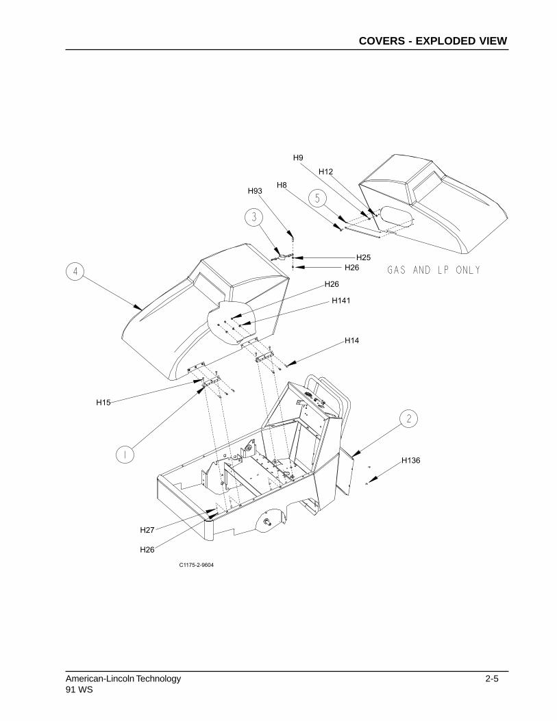
American-Lincoln Technology 2-591 WS
H14
H136
H27
H26
H15
H26
H141
H12
H8H93
H26
H25
H9
C1175-2-9604
COVERS - EXPLODED VIEW

2-6 American-Lincoln Technology91 WS
KEY NO. PART NUMBER DESCRIPTION QTY.
1 8-23-03067 Washer, Fwd/Rev Outer 12 8-03-04312 Arm, Forward/Reverse 13 8-23-03066 Washer, Fwd/Rev Inner 14 8-58-05276 Washer, Fwd/Rev 15 8-60-00183 Idler Pulley 1
6 8-60-00177 Idler Pulley (Fwd/Rev) 17 2-00-03306 Bearing 28 8-42-05138 Link 19 8-25-02019 Ball Joint 210 2-00-02172 Rod, Clutch Centering 1
11 2-95-04182 Nut, Fiber 112 8-76-00053 Spring 113 8-31-06085 Control Handle 114 8-31-06088 Handle, Clutch (Welded) 115 8-08-00798 Bracket, Clutch Handle 2
16 2-00-05284 Belt, Forward 117 2-00-05285 Belt, Reverse 118 8-75-01115 Spacer, .875 x .375 x .940 119 8-08-00828 Bracket, Clutch Handle 2
HARDWARE USED:
H9 2-00-00426 Flat Washer, .500 x .219 x .063 3H12 2-00-01246 Nut, Hex Fiber Insert #10 - 24 3H15 2-00-00221 Screw, 1/4-20 x .750 HHC 2H36 2-00-00196 Carriage Bolt, 5/16-18 x 1.000 4H43 2-00-00409 Flat Washer, .687 x .344 x .062 2H46 2-00-00644 Nut, 5/16-18, Insert Fiber 10H52 2-00-00402 Flat Washer, .750 x .390 x .094 4H62 2-00-00405 Flat Washer, 1.063 x .531 x .094 4H65 2-00-04936 Nut, 1/2-13 Fiber Lock 1H102 2-00-04795 Screw, #10-24 x .750 BHS 3H131 2-00-03855 Carriage Bolt, 2/8-16 x 1.000 2H134 2-00-03032 Screw, 3/8-16 x .750 FHS 2H140 2-00-00447 Flat Washer, 1.250 x .280 x .090 2H141 2-00-00501 Lock Washer, Int. 2H142 2-00-05244 Carriage Bolt, 1/2-13 x 2.000 2H143 2-00-00432 Flat Washer, 1.130 x .770 x .063 4H144 2-00-02303 Lock Washer, Int. 8H146 2-00-00420 Flat Washer, 1.000 x .516 x .063 2
C1176-1
WHEEL DRIVE - PARTS LIST

American-Lincoln Technology 2-791 WS
H46
H43H139
H38
H62
H59
H52
H137
H52
H52
H65
H62H146
H26H34
H79
H12
H112
H46
H76
C1176-1/9604
WHEEL DRIVE - EXPLODED VIEW

2-8 American-Lincoln Technology91 WS
KEY NO. PART NUMBER DESCRIPTION QTY.
1 0885-086 Differential 12 8-08-00800 Bracket, Differential Bearing 13 2-00-03997 Bearing, Flange 24 8-25-06012 Flange, Welded 15 8-89-08072 Drive Wheel 2
6 8-65-00046 Axle Retainer 27 8-75-05069 Idler Sprocket 28 8-60-00178 Differential Pulley 19 2-00-04636 Ball Bearing 510 8-75-01202 Spacer, Wheel 2
11 8-76-05023 Idler Sprocket 212 8-76-05013 Drive Sprocket 213 2-00-03306 Bearing 214 2-00-05295 Screw, 5/16-18 x 2.000 HSHC 815 8-75-01208 Chain 2
16 2-00-00264 Screw, 5/16 HS-KCP 217 2-00-02227 Key, Square 1/8 x .750 218 2-95-04182 Nut, Fiber 219 8-75-01208 Differential Spacer 4
HARDWARE USED:
H9 2-00-00426 Flat Washer, .500 x .219 x .063 3H12 2-00-01246 Nut, Hex Fiber Insert #10-24 3H15 2-00-00221 Screw, 1/4-20 x .750 HHC 1H36 2-00-00196 Carriage Bolt, 5/16-18 x 1.000 4H43 2-00-00409 Flat Washer, .687 x .344 x .062 4H46 2-00-00644 Nut, 5/16-18, Insert Fiber 8H48 2-00-00233 Screw, 3/8-16 x 1.000 HHC 2H52 2-00-00402 Flat Washer, .750 x .390 x .094 4H62 2-00-00405 Flat Washer, 1.063 x .531 x .094 15H65 2-00-04936 Nut, 1/2-13 Fiber Lock 2H82 2-00-00505 Lock Washer, 3/8 Int. Tooth 2H102 2-00-04795 Screw, #10-24 x .750 BHS 3H131 2-00-03855 Carriage Bolt, 3/8-16 x 1.000 2H134 2-00-03032 Screw, 3/8-16 x .750 FHS 2H140 2-00-00447 Flat Washer, 1.250 x .280 x .090 2H141 2-00-00501 Lock Washer, Int. 2H142 2-00-05244 Carriage Bolt, 1/2-13 x 2.000 2H143 2-00-00432 Flat Washer, 1.13 x .770 x .063 4H144 2-00-02303 Lock Washer, Int. 8H146 2-00-00420 Flat Washer, 1.000 x .516 x .063 4
C-1176-2
LOWER WHEEL DRIVE - PARTS LIST

American-Lincoln Technology 2-991 WS
H134H62
H62
H140H141
H15
H62
H65
H144
H143
H52
H82
H48
H102
H12
H46
H36
H43 H46
H146
H52
H140
H141
H15
H9
H62H146
H142H131
C1176-2/9604
LOWER WHEEL DRIVE - EXPLODED VIEW

2-10 American-Lincoln Technology91 WS
KEY NO. PART NUMBER DESCRIPTION QTY
1 8-81-00176 Main Broom Arm Support 123 7-39-00025 Knob 14 2-00-02049 Bearing 25 7-60-00141 Pulley 1
6 8-03-04308 Arm, Belt Idler (Upper) 17 8-03-04307 Arm, Belt Idler (Lower) 18 8-60-00174 Pulley, Idler (Main Broom) 29 2-00-03306 Bearing 210 8-41-05082 Lever, Main Broom 1
11 8-66-00174 Rod, Main Broom 112 2-10-01336 Spring 113 2-95-04182 Nut, Fiber 114 7-31-06066 Handle, Grip 1.000 x .250 115 8-79-00030 Strap, Static 1
16 2-00-05314 Belt 117 2-00-01036 Belt 118 8-76-00053 Spring 219 8-08-00809 Retainer 1
HARDWARE USED:
H36 2-00-00196 Carriage Bolt, 5/16-18 x 1.000 1H37 2-00-00207 Screw, 5/16-18 x 1.000 1H43 2-00-00409 Flat Washer, .687 x .344 x .062 1H46 2-00-00644 Nut, 5/16-18 Insert Fiber 5H48 2-00-00233 Screw, 3/8-16 x 1.000 HHC 1H49 2-00-00209 Screw, 3/8-16 x 1.250 HHC 2H52 2-00-00402 Flat Washer, .750 x .390 x .094 3H54 2-00-02360 Nut, 3/8-16 Hex. 1H65 2-00-04936 Nut, 1/2-13 Fiber Lock 2H125 2-00-00418 Flat Washer, .984 x .627 x .063 8H144 2-00-02303 Lock Washer, Int. 4H146 2-00-00420 Flat Washer, 1.000 x .516 x .063 5H147 2-00-00642 Nut, Fiber Insert 5/18-18 1H148 2-00-01778 Screw, 1/2-13 x 2.000 HHC 1H149 2-00-01803 Washer, 1.063 x .031 x .063 2
C1177-2/9604
MAIN BROOM - PARTS LIST

American-Lincoln Technology 2-1191 WS
H146
H146
H33
H144
H144
H149
H120
H48
H36
H49
H65
H65
H37
H125
H125
H125
H147
H125
H43
H46
H52
H54
H52 H46 H43
H34
H148
H148C1177-2/9707
MAIN BROOM - EXPLODED VIEW

2-12 American-Lincoln Technology91 WS
KEY NO. PART NUMBER DESCRIPTION QTY.
1 8-70-05291 Broom Shaft 12 8-03-04311 Arm, Broom (R.H.) 13 8-03-04310 Arm, Broom Idler 14 2-00-02243 Key 25 2-00-03158 Spacer 2
6 7-60-00142 Pulley 17 8-33-09062 Driver Hub 18 8-30-05112 Guard 19 8-33-09059 Idler Hub 110 2-00-02049 Bearing 4
11 8-15-01002 Collar, Setscrew 412 2-00-03306 Bearing 213 2-95-01931 Setscrew 114 8-08-03216 Main Broom - Proex Ref.
8-08-03222 Main Broom - Nylon Ref.8-08-03223 Main Broom - Nylon High Density Ref.8-08-03230 Main Broom - Proex & Wire Ref.
HARDWARE USED:
H14 2-00-00219 Screw, 1/4-20 x .500 HHC 2H61 2-00-02616 Screw, 1/2-13 x 3.000 HHC 1H65 2-00-05936 Nut, 1/2-13 Fiber Lock 1H125 2-00-00418 Flat Washer, .984 x .627 x .063 8H141 2-00-00501 Lock Washer, Int. 2H145 2-00-04180 Setscrew, 1/4-20 x .500 2
C1177-1
MAIN BROOM ARMS - PARTS LIST

American-Lincoln Technology 2-1391 WS
C1177-1
H61
H141
H14
H65H145
H44
H33H125
MAIN BROOM ARMS - EXPLODED VIEW

2-14 American-Lincoln Technology91 WS
KEY NO. PART NUMBER DESCRIPTION QTY
1 8-03-04313 Side Broom Arm (Welded) 12 0885-087 Gear Box Assembly 13 8-08-03215 Side Broom 1
8-08-03231 Side Broom Nylon 14 8-25-06006 Flange 15 8-60-00184 Pulley, Gear Box 1
6 7-76-00051 Spring 17 8-08-00806 Bracket, Side Broom (Outer) 18 7-76-00003 Spring 19 8-08-00809 Retainer, Side Broom Link 110 8-08-00807 Bracket, Side Broom (Inner) 1
11 8-81-00170 Support, Gear Box Mounting 112 8-58-05277 Plate, Side Broom Arm 113 8-66-00175 Rod, Side Broom Link 114 2-00-05286 Belt 115 8-55-08126 Safety Snap Pin 1
16 2-00-02240 Key, 3/16 x .750 117 7-09-01057 Bushing 218 7-21-04042 Edging 1
HARDWARE USED:
H16 2-00-03051 Screw, 1/4-20 x .750 HSHC 3H20 2-00-00203 Screw, 1/4-20 x 1.500 HHC 1H22 2-00-02589 Screw, 1/4-20 x 2.000 HHC 3H25 2-00-00594 Nut, Hex 1/4-20 x .437 x .218 1H26 2-00-00641 Nut, 1/4-20 Insert Fiber 11H27 2-00-03702 Washer, .625 x .281 x .063 5H36 2-00-00196 Carriage Bolt, 5/16-18 x 1.000 3H37 2-00-00207 Screw, 5/16-18 x 1.250 HHC 1H40 2-00-01770 Screw, 5/16-18 x 2.750 HHC 1H43 2-00-00409 Flat Washer, .687 x .344 x .062 2H46 2-00-00644 Nut, 5/16-18, Insert Fiber 6H62 2-00-00405 Flat Washer, 1.063 x .531 x .094 1H128 2-00-04681 Carriage Bolt, 5/16-18 x 1.250 1H135 2-00-05298 Flat Washer, .344 x 2.000 x .062 4H150 2-00-00211 Screw, 5/16-18 x 1.750 HHC 1
C1182
RIGHT HAND SIDE BROOM - PARTS LIST

American-Lincoln Technology 2-1591 WS
C-1182
H46
H36H62
H150
H43
H43
H37
H20
H16H46
H46
H135
H36
H128
H150H40
H27
H26
H22
H46
H26
H25
H135
BELT DIAGRAM
13
17
12
11
16
15
17
18
6
2
4
3
17
8
9
10
14
5
MOTORPULLEY
RIGHT HAND SIDE BROOM - EXPLODED VIEW

2-16 American-Lincoln Technology91 WS
KEY NO. PART NUMBER DESCRIPTION QTY.
1 8-32-06103 Hopper (Plastic) 12 8-13-07130 Clamp - Filter (Rear) 13 8-13-07131 Clamp - Filter (Front) 14 8-66-00177 Rod - Filter Tie 25 8-13-07124 Clamp - Hopper Flap 1
6 8-25-08208 Flap - Hopper 17 8-13-07133 Clamp - Hopper Lip 28 8-41-00058 Latch - Hopper Lift 19 8-31-06087 Handle - Hopper Lift 110 2-95-03355 Handle - Grip 1
11 7-31-06064 Handle 212 8-70-05301 Shaft - Hopper Pivot 113 8-15-01003 Collar 114 7-76-00112 Spring - Tie Rods 215 8-24-04074-1 Filter 1
16 8-51-05018 Pan - Filter Debris 117 2-00-01415 Pin - Roll Dia. .25 x 1.50 118 8-29-00247 Gasket 219 2-00-00246 Screw 120 2-00-02968 Screw 6
HARDWARE USED:
H8 2-00-00039 Screw, 10-24 x 1.000 RHM 5H12 2-00-01246 Nut, Hex Fiber Insert #10-24 5H15 2-00-00221 Screw, 1/4-20 x .750 HHC 5H26 2-00-00641 Nut, 1/4-20 Insert Fiber 10H27 2-00-03702 Washer, .625 x .281 x .063 10H100 2-00-03062 Screw, #10-24 x .625 THM 4H126 2-00-03466 Screw, #10-16 x .500 15
C1178/9610
HOPPER - PARTS LIST

American-Lincoln Technology 2-1791 WS
H27
H27
H27
H27
H27
H8
H12
H26
H26
H26
H26
H126
H126
H100
H15H15
C1178/9705
HOPPER - EXPLODED VIEW

2-18 American-Lincoln Technology91 WS
KEY NO. PART NUMBER DESCRIPTION QTY.
1 8-24-04140 Manifold, Filter 12 8-08-00817 Filter Manifold Bracket 13 8-08-00819 Filter Manifold Bracket 14 8-33-02331 Hose, Impeller Inlet 15 8-41-00033 Filter Manifold Latch 1
6 8-55-08114 Shaker Pivot Pin 17 7-58-05278 Shaker Motor Plate 18 7-03-04135 Arm, Shaker 19 8-16-07406 Motor Hold Down 110 0860-623 Motor 1
11 8-89-04019 Weight, Filter Shaker 112 8-15-01016 Collar, Filter Shaker 413 8-29-00228 Gasket, Impeller Manifold 214 8-29-00229 Gasket, Impeller Manifold 215 7-13-07104 Clamp, Hose Impeller Inlet 1
16 8-76-00053 Spring 217 2-00-04937 Tie Raps 1
HARDWARE USED:
H6 2-00-00049 Screw, #10-24 x .500 RHM 2H10 2-00-00519 Lock Washer, #10 Med. HS 2H11 2-00-00605 Nut, Hex MS #10-24 x .375 x .125 2H15 2-00-00221 Screw, 1/4-20 x .750 HHC 2H20 2-00-00203 Screw, 1/4-20 x 1.500 HHC 2H25 2-00-00594 Nut, Hex 1/4-20 x .437 x .218 2H26 2-00-00641 Nut, 1/4-20 Insert Fiber 12H27 2-00-03702 Washer, .625 x .281 x .063 10H86 2-00-03575 Carriage Bolt, 1/4-20 x .750 12H126 2-00-03466 Screw, #10-16 x .500 2H136 2-00-03940 Screw, #10-24 x .500 T/C HH 1H287 2-00-00264 Set Screw, ¼-20 x .313 HSKCP
C1179-1
FILTER SHAKER - PARTS LIST

American-Lincoln Technology 2-1991 WS
C1179-1/9907
H86
8 H27 H26
H26
H27
12
H86
910
H287
11
7
6
H11
H10
H15
16H27
H26
3
H26
H86
H26
H25
H20
1
13
H126
5
H6
H136
17
144
15
2
FILTER SHAKER - EXPLODED VIEW

2-20 American-Lincoln Technology91 WS
KEY NO. PART NUMBER DESCRIPTION QTY.
1 8-16-07392 Plate Impeller Cover 12 8-81-00172 Support, Impeller 13 8-70-05296 Impeller Shaft 14 8-60-00182 Impeller Drive Pulley 15 2-95-04317 Bearing, Impeller Shaft 2
6 8-23-00012 Impeller Fan 17 8-75-01203 Spacer, Impeller Cover 38 8-03-04314 Arm, Hopper Latch 19 8-08-00809 Bracket, Latch Arm 110 7-13-07104 Clamp, Hose (Impeller Inlet) 1
11 7-76-00096 Spring 112 2-95-04182 Nut, Fiber 413 8-15-01016 Collar, Filter Shaker 114 2-00-00709 Key, Square 3/16 x 1.000 115 2-00-02227 Key, Square 1/8 x .750 1
16 2-00-05200 Belt 117 8-16-07393 Bypass Cover 118 7-31-06072 Handle Grip 119 8-18-00433 Decal - Wet Sweep Bypass 120 7-23-03048 Washer, Frict - Spr - Shakeproof 2
HARDWARE USED:
H17 2-00-00205 Screw, 1/4-20 x 1.000 HHC 1H26 2-00-00641 Nut, 1/4-20 Insert Fiber 3H27 2-00-03702 Washer, .625 x .281 x .063 2H35 2-00-02708 Screw, 5/16-18 x 1.000 HHM 1H36 2-00-00196 Carriage Bolt, 5/16-18 x 1.000 1H43 2-00-00409 Flat Washer, .687 x .344 x .062 4H46 2-00-00644 Nut, 5/16-18, Insert Fiber 3H48 2-00-00233 Screw, 3/8-16 x 1.000 HHC 4H52 2-00-00402 Flat Washer, .750 x .390 x .094 4H141 2-00-00501 Lock Washer, Int. 1H169 2-00-02637 Screw, 1/4-20 x 2.750 HHC 3
C1179-2/9705
IMPELLER - PARTS LIST

American-Lincoln Technology 2-2191 WS
H26
C1179-2/9610
REAR COVER
H46
H43
H36
H35
APPLY NEVER - SIEZE
H48H52
H26H27
H141
H169
H17
H46H43
BELT DIAGRAM
19
18
10
17
20
13
12
11
15
14
6
5
3
9
84
2
71
16
IMPELLER -EXPLODED VIEW

2-22 American-Lincoln Technology91 WS
KEY NO. PART NUMBER DESCRIPTION QTY
1 8-81-00175 Battery Support (Welded) 12 8-81-00174 Motor Support 13 8-75-01204 Battery Spacer 14 0875-085 Battery, 12 VDC Ref.5 0882-054 Motor, 1.3 H.P., 24 VDC 1
6 8-51-05014 Battery Pan 27 8-60-00176 Pulley, Impeller Drive 18 8-60-00175 Pulley, Broom Drive 19 8-09-01082 Grommet 110 8-74-00010 Solenoid, 24 VDC 1
11 8-06-05004 Isolation Post 312 8-28-05019 Fuse, 70A 113 0875-118 24 VDC Connector Ref.14 2-00-02259 Key, 3/16 x 2.000 Lg. 115 2-00-04564 Clamp 1
16 8-20-06043 Duct, Wire 117 2-95-04182 Nut, Fiber 3/8-16 1018 2-00-04603 Clamp 1
HARDWARE USED:
H1 2-00-05060 Screw, #6-32 x 1.250 RHM 1H5 2-00-00645 Nut, Hex Fiber Insert #6-32 2H10 2-00-00605 Nut, Hex MS #10 x .375 x .125 2H12 2-00-01246 Nut, Hex Fiber Insert #10-24 3H15 2-00-00221 Screw, 1/4-20 x .750 HHC 2H26 2-00-00641 Nut, 1/4-20 Insert Fiber 5H27 2-00-03702 Washer, .625 x .281 x .062 3H43 2-00-00409 Flat Washer, .687 x .344 x .062 5H46 2-00-00644 Nut, 5/16-18, Insert Fiber 13H52 2-00-00402 Flat Washer, .750 x .390 x .094 1H62 2-00-00405 Flat Washer, 1.063 x .531 x .094 2H90 2-00-03569 Carriage Bolt, 5/16-18 x .750 4H128 2-00-04681 Carriage Bolt, 5/16-18 x 1.250 1H131 2-00-03855 Carriage Bolt, 3/8-16 x 1.000 8H144 2-00-02303 Lock Washer, Int. 1H149 2-00-01803 Washer, 1.063 x .031 x .063 1H161 2-00-00153 Screw, #8-24 x .875 OHM 3H162 2-00-03961 Screw, 5/16-24 x 1.000 HHC 1H163 2-00-03570 Carriage Bolt, 3/8-16 x .750 2
C1187
BATTERY - PARTS LIST

American-Lincoln Technology 2-2391 WS
H46
H43
H11
H9
H2
H12
H5
H27
H90
H8
H1
H27
H52
H4
H12
H43
H46
H26
H90
H90
H128
H15
H144
H149
H26
H62
H52H162
H163
H46
H131
H161
C1187/0009
BATTERY - EXPLODED VIEW

2-24 American-Lincoln Technology91 WS
KEY NO. PART NUMBER DESCRIPTION QTY
1 0877-053 Engine, 8 H.P. 12 8-51-05017 Battery Pan 13 0775-117 Battery, 12 Volt 14 8-60-00181 Pulley 15 8-58-05278 Plate, Engine Mounting 1
6 2-00-04589 Fitting, 3/8 NPT x 90° 17 8-56-05011 Nipple, 3/8 NPT x 3.000 Lg. 18 2-00-03646 Cap, 3/8 NPT 19 2-95-04182 Nut, Fiber 710 2-00-03761 Key, 1/4 x 2.000 1
11 8-16-00055 Choke Cable 112 2-95-04012 Flat Washer, 1.500 x .468 x .093 113 8-11-00042 Fuel Gauge 114 8-72-00011 Impeller Shroud 115 8-08-00840 Bracket, Engine Brace 1
16 8-08-00841 Bracket, Engine Brace 117 8-49-00026 Muffler, Deflector 118 2-00-03836 Screw 219 2-00-04652 Screw, 7/16-20 x 1.500 HHC 1
HARDWARE USED:
H15 2-00-00221 Screw, 1/4-20 x .750 HHC 2H26 2-00-00641 Nut, 1/4-20 Insert Fiber 3H33 2-00-00224 Screw, 5/16-18 x .500 HHC 3H35 2-00-02708 Screw, 5/16-18 x 1.000 HHM 1H39 2-00-00218 Screw, 5/16-18 x 2.000 HHC 2H43 2-00-00409 Flat Washer, .687 x .344 x .062 4H46 2-00-00644 Nut, 5/16-18, Insert Fiber 5H48 2-00-00233 Screw, 3/8-16 x 1.000 HHC 2H49 2-00-00209 Screw, 3/8-16 x 1.250 HHC 1H52 2-00-00402 Flat Washer, .750 x .390 x .094 2H62 2-00-00405 Flat Washer, 1.063 x .531 x .094 2H82 2-00-00505 Lock Washer, 3/8 Int. Tooth 2H120 2-00-03829 Lock Washer, 3/8 Bolt 2H129 2-00-02311 Lock Washer, 4.38 Spit 1H131 2-00-03855 Carriage Bolt, 3/8-16 x 1.000 6H132 2-00-00503 Lock Washer, 1/4 Ext. 1H144 2-00-02303 Lock Washer, Int. 6H151 2-00-00213 Screw, 5/16-18 x .625 HHC 1H313 2-00-04652 Screw, HHC .438-20 x 1.50 1H314 2-00-03836 Bolt Carriage, .31-18x 1.75 2
C1184/9610
ENGINE - PARTS LIST

American-Lincoln Technology 2-2591 WS
16
159
8
7
6
124
10
H49
H52
H35
H52
H120
H48H82
H129
H46
H144
H39
H151
H33
H144
H43
H120
H62
H131
5
9
14
17
H26
H132
1
13
2
3
H144
H46
STARTERPOST
H26
H15
H313
H314C1184/9907
ENGINE - EXPLODED VIEW

2-26 American-Lincoln Technology91 WS
KEY NO. PART NUMBER DESCRIPTION QTY
1 2-00-04345 Tie Raps 72 0775-159 Diode Assembly 13 0875-118 Connector Assembly, 24 VDC 14 0875-119 Connector Assembly, 24 VDC 15 8-90-07441 Wire, Jumper #4A 2
6 0895-113 Machine Harness 17 7-90-07286 Wire, Jumper 18 2-00-04203 Boot, Black 39 8-90-07440 Wire, Solenoid to 70A Fuse 110 2-00-04952 Boot, Red 1
11 2-00-04869 Terminal, .31 Ring 112 2-00-04868 Terminal, .25 Ring 1
C1189-2
ELECTRICAL ASSEMBLY (BATTERY) - PARTS LIST

American-Lincoln Technology 2-2791 WS
OFF
OFF
FILTERSHAKER CB-1CB-2
ON
M
M
A
B S
GI
BACK WIRING VIEW TOP
POWER PANEL
BOTTOM VIEWM1 RELAY
1 2 3 4
85
30
86
87
WIRE #4
9
8
12
10
4
3
1
1
3
2
6
7 5
112
M1
20 SEC.TIMER
WIR
ED
UC
T
70 A FUSE
SOL.1A
(-) POST
ROUTETHROUGHCLAMP
(+) MOTOR LEAD
A
(-) MOTORLEAD
RED
BLK.SHAKERMOTOR
RED
FROMBATTERIES
TO (-) POSTTO BOTTOM70 A FUSE
RED
BLK.BLK.
C1189-2/9911
ELECTRICAL ASSEMBLY (BATTERY) - EXPLODED VIEW

2-28 American-Lincoln Technology91 WS
KEY NO. PART NUMBER DESCRIPTION QTY
1 2-00-04345 Tie Raps 72 2-00-04584 Terminal, .156 Female Bullet 13 2-00-04578 Terminal, .156 Male Bullet 14 8-90-07435 Wire, Battery (-) 15 8-90-07436 Wire, Starter 1
6 0895-112 Machine Harness 17 8-90-07441 Wire, Jumper #4A 28 2-00-04203 Boot, Black 39 8-90-07352 Wire, Battery (+) to Start Solenoid 110 2-00-04952 Boot, Red 1
C1186-2
ELECTRICAL ASSEMBLY (GAS) - PARTS LIST

American-Lincoln Technology 2-2991 WS
OFF
OFF
CHOKE
LOWOIL
FILTERSHAKER CB-1CB-2
START ON
M
M
A
B S
G
I
BACK WIRING VIEWTOP
BOTTOM VIEWM1 RELAY
8 HP B&SENG.
1 2 3 4
85
30
86
87
RED
RED
RED
A
B
WIRE #4
68
8
7
2
3
910
5
4
GND.STUD
STARTSOL.
M1
20 SEC.TIMER
BATTERY
WHT.WIRE
RED BLK.SHAKERMOTOR
REG.
STARTERMOTOR
C1186-2
ELECTRICAL ASSEMBLY (GAS) - EXPLODED VIEW

2-30 American-Lincoln Technology91 WS
KEY NO. PART NUMBER DESCRIPTION QTY
1 8-33-05126 Control Housing 12 8-64-00015 Shaker Timer Motor 13 8-64-00007 Circuit Breaker 24 8-64-00012 Relay, Shaker Motor 15 2-00-04757 Plug Button, .375 1
6 2-00-05296 Plug Button, .620 17 8-48-05023 Hour Meter 18 8-82-00057 Key Switch 19 8-11-00044 Boot (CB) 210 8-48-05030 Battery Condition Meter 1
11 7-13-07069 Adjustable Clamp 112 8-82-00059 Switch, Rocker 1
HARDWARE USED:
H9 2-00-00426 Flat Washer, .500 x .219 x .063 2H12 2-00-01246 Nut, Hex Fiber Insert #10-24 2H15 2-00-00221 Screw, 1/4-20 x .750 HHC 2H26 2-00-00641 Nut, 1/4-20 Insert Fiber 2H34 2-00-00208 Screw, 5/16-18 x .750 HHC 4H43 2-00-00409 Flat Washer, .687 x .344 x .062 4H46 2-00-00644 Nut, 5/16-18, Insert Fiber 4H103 2-00-00089 Screw, 10-24 x 1.500 RHM 2
C1180/9604
CONTROL PANEL (BATTERY) - PARTS LIST

American-Lincoln Technology 2-3191 WS
H12
H9
H46
H26
H15
H103
H34
H43
C1180/9604
CONTROL PANEL (BATTERY) - EXPLODED VIEW
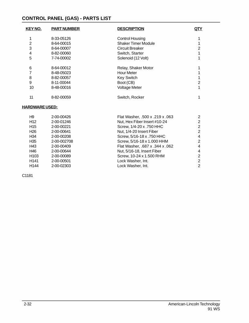
2-32 American-Lincoln Technology91 WS
KEY NO. PART NUMBER DESCRIPTION QTY
1 8-33-05126 Control Housing 12 8-64-00015 Shaker Timer Module 13 8-64-00007 Circuit Breaker 24 8-82-00060 Switch, Starter 15 7-74-00002 Solenoid (12 Volt) 1
6 8-64-00012 Relay, Shaker Motor 17 8-48-05023 Hour Meter 18 8-82-00057 Key Switch 19 8-11-00044 Boot (CB) 210 8-48-00016 Voltage Meter 1
11 8-82-00059 Switch, Rocker 1
HARDWARE USED:
H9 2-00-00426 Flat Washer, .500 x .219 x .063 2H12 2-00-01246 Nut, Hex Fiber Insert #10-24 2H15 2-00-00221 Screw, 1/4-20 x .750 HHC 2H26 2-00-00641 Nut, 1/4-20 Insert Fiber 2H34 2-00-00208 Screw, 5/16-18 x .750 HHC 4H35 2-00-002708 Screw, 5/16-18 x 1.000 HHM 2H43 2-00-00409 Flat Washer, .687 x .344 x .062 4H46 2-00-00644 Nut, 5/16-18, Insert Fiber 4H103 2-00-00089 Screw, 10-24 x 1.500 RHM 2H141 2-00-00501 Lock Washer, Int. 2H144 2-00-02303 Lock Washer, Int. 2
C1181
CONTROL PANEL (GAS) - PARTS LIST

American-Lincoln Technology 2-3391 WS
H103
H15
H27
H26
H46
H43
H34
H144
H9H12
C1181
CONTROL PANEL (GAS) - EXPLODED VIEW

2-34 American-Lincoln Technology91 WS
KEY NO. PART NUMBER DESCRIPTION QTY
1 8-18-00411 Decal, Warning Moving Parts 32 8-18-00409 Decal, Control Panel 13 8-18-00408 Decal, Main Broom 14 8-18-00407 Decal, General Warning 15 8-18-00406 Decal, Key Switch Warning 1
6789 8-18-00413 Decal, Caution Hopper 110
11 8-50-00014 Serial Tag A-L 112 2-00-04115 Rivets 21314 8-18-00420 Decal, Main Broom Adjustment 115 7-18-00228 Decal, Patent 1
16 8-18-00404 Decal, Charging 117 8-18-00412 Decal, Electrical Hazard 118 8-18-00429 Decal, On-Off 1
C1183/9907
DECALS (BATTERY) - PARTS LIST

American-Lincoln Technology 2-3591 WS
CB-1 CB-2FILTER SHAKERFILTER SHAKER
OFF
OFFON
FLOAT
SWEEP
UP
MAINBROOM
MAINBROOM
WARNINGUNEXPECTED MOVEMENT COULD RESULT INPERSONAL INJURY OR PROPERTY DAMAGE.UNEXPECTED MOVEMENT COULD RESULT INPERSONAL INJURY OR PROPERTY DAMAGE.
TURN KEY SWITCH TO "OFF" AND PARKMACHINE ON LEVEL SURFACE BEFORELEAVING OPERATOR'S POSITION
TURN KEY SWITCH TO "OFF" AND PARKMACHINE ON LEVEL SURFACE BEFORELEAVING OPERATOR'S POSITION
MAIN BROOMPRESSURE
MAIN BROOMPRESSURE
HEAVY
LIGHT
WARNINGTO PREVENT SERIOUSINJURY STAY CLEAR OFMOVING PARTS
TO PREVENT SERIOUSINJURY STAY CLEAR OFMOVING PARTS
243
14
18
1
5
CB
-1C
B-1
CB
-2C
B-2
FILT
ER
SH
AK
ER
FILT
ER
SH
AK
ER
BA
TT
ER
YC
ON
DIT
ION
BA
TT
ER
YC
ON
DIT
ION
CH
EC
KW
HIL
EO
PE
RA
TIN
G
CH
EC
KW
HIL
EO
PE
RA
TIN
G
OF
FO
FF
OF
FO
FF
ON
-+
FL
OA
TF
LO
AT
SW
EE
PS
WE
EPUP
UP
MA
INB
RO
OM
MA
INB
RO
OM
CA
UT
ION
CA
UT
ION
PR
EV
EN
TB
AC
KS
TR
AIN
, DO
NO
T
RE
MO
VE
HO
PP
ER
WIT
HO
UT
HE
LP.
ALW
AY
SU
SE
LE
VE
RTO
DU
MP
HO
PP
ER
PR
EV
EN
TB
AC
KS
TR
AIN
, DO
NO
T
RE
MO
VE
HO
PP
ER
WIT
HO
UT
HE
LP.
ALW
AY
SU
SE
LE
VE
RTO
DU
MP
HO
PP
ER
WARNINGWARNINGTO PREVENT SERIOUSINJURY STAY CLEAR OFMOVING PARTS
TO PREVENT SERIOUSINJURY STAY CLEAR OFMOVING PARTS
WARNINGELECTRICAL HAZARD SHOCKS
CAN CAUSE PERSONAL INJURYELECTRICAL HAZARD SHOCKS
CAN CAUSE PERSONAL INJURY
DISCONNECT BATTERY BEFOREWORKING IN THIS AREA.
DISCONNECT BATTERY BEFOREWORKING IN THIS AREA.
REPAIRS MUST BE PERFORMEDBY AUTHORIZED PERSONNEL ONLY.
REPAIRS MUST BE PERFORMEDBY AUTHORIZED PERSONNEL ONLY.
A
A
1
1
9
16
11
1715
12
WARNING
1. MAINTAIN ELECTROLYTE LEVELIN BATTERIES, CHECK BEFORE
CHARGING.
1. MAINTAIN ELECTROLYTE LEVELIN BATTERIES, CHECK BEFORE
CHARGING.
2. INSERT CHARGING PLUG INTOBATTERY RECEPTACLE
2. INSERT CHARGING PLUG INTOBATTERY RECEPTACLE
3. PLUG POWER CORD INTO PROPERAC SOURCE.
3. PLUG POWER CORD INTO PROPERAC SOURCE.
4. KEEP COVER OPEN WHILE CHARGING.4. KEEP COVER OPEN WHILE CHARGING.
5. FOLLOW DIRECTIONS ON CHARGER.5. FOLLOW DIRECTIONS ON CHARGER.
BATTERIES GENERATE EXPLOSIVE HYDROGENGAS. KEEP SPARKS AND FLAME AWAY FROMBATTERIES. NO SMOKING.
BATTERIES MUST BE CHARGED IN AN AREAWITH GOOD VENTILATION. KEEP COVER OPENWHILE CHARGING BATTERIES.
BATTERIES GENERATE EXPLOSIVE HYDROGENGAS. KEEP SPARKS AND FLAME AWAY FROMBATTERIES. NO SMOKING.
BATTERIES MUST BE CHARGED IN AN AREAWITH GOOD VENTILATION. KEEP COVER OPENWHILE CHARGING BATTERIES.
REMOVE ALL JEWELRY. ALWAYS WEAR EYEPROTECTION AND PROTECTIVE CLOTHINGWHEN WORKING NEAR BATTERIES
DO NOT PUT TOOLS OR OTHER OBJECTSACROSS THE BATTERY TERMINALS OR ONTOP OF BATTERIES.
REMOVE ALL JEWELRY. ALWAYS WEAR EYEPROTECTION AND PROTECTIVE CLOTHINGWHEN WORKING NEAR BATTERIES
DO NOT PUT TOOLS OR OTHER OBJECTSACROSS THE BATTERY TERMINALS OR ONTOP OF BATTERIES.
TO PREVENT SPARKS WHICH COULD CAUSEAN EXPLOSION, DO NOT DISCONNECT THECHARGER PLUG FROM THE BATTERIES WITHTHE CHARGER ON.
TO PREVENT SPARKS WHICH COULD CAUSEAN EXPLOSION, DO NOT DISCONNECT THECHARGER PLUG FROM THE BATTERIES WITHTHE CHARGER ON.
CHARGING INSTRUCTIONSCHARGING INSTRUCTIONS
C1183/9604
DECALS (BATTERY) - EXPLODED VIEW

2-36 American-Lincoln Technology91 WS
KEY NO. PART NUMBER DESCRIPTION QTY
1 8-18-00411 Decal, Warning Moving Parts 32 8-18-00410 Decal, Control Panel 13 8-18-00408 Decal, Main Broom 14 8-18-00407 Decal, General Warning 15 8-18-00406 Decal, Key Switch Warning 1
6 8-18-00405 Decal, Engine Warning 1789 8-18-00413 Decal, caution Hopper 110 8-18-00085 Decal, Fuel Hazard 1
11 8-50-00014 Serial Tag A-L 112 2-00-04115 Rivets 213 8-18-00421 Decal, Exhaust Warning 114 8-18-00420 Decal, Main Broom Adjustment 115 7-18-00228 Decal, Patent 1
16 8-18-00429 Decal, On-Off 1
C1183-1/9907
DECALS (GAS) - PARTS LIST

American-Lincoln Technology 2-3791 WS
CHOKE START
CB-1 CB-2FILTER SHAKER
OFF
OFFON
FLOAT
SWEEP
UP
MAINBROOM
MAINBROOM
WARNINGUNEXPECTED MOVEMENT COULD RESULT INPERSONAL INJURY OR PROPERTY DAMAGE.
TURN KEY SWITCH TO "OFF" AND PARKMACHINE ON LEVEL SURFACE BEFORELEAVING OPERATOR'S POSITION
MAIN BROOMPRESSURE
MAIN BROOMPRESSURE
HEAVY
LIGHT
WARNINGTO PREVENT SERIOUSINJURY STAY CLEAR OFMOVING PARTS
CB
-1C
B-2
CB
-2F
ILTE
RS
HA
KE
R
FILT
ER
SH
AK
ER
BA
TT
ER
YC
ON
DIT
ION
BA
TT
ER
YC
ON
DIT
ION
CH
EC
KW
HIL
EO
PE
RA
TIN
G
CH
EC
KW
HIL
EO
PE
RA
TIN
G
OF
FO
FF
OF
FO
FF
ON
ON
-+
FL
OA
TF
LO
AT
SW
EE
PS
WE
EPUP
UP
MA
INB
RO
OM
MA
INB
RO
OM
EF
WARNINGTO PREVENT SERIOUSINJURY STAY CLEAR OFMOVING PARTS
CA
UT
ION
PR
EV
EN
TB
AC
KS
TR
AIN
, DO
NO
T
RE
MO
VE
HO
PP
ER
WIT
HO
UT
HE
LP.
ALW
AY
SU
SE
LE
VE
RTO
DU
MP
HO
PP
ER
WARNINGEngine exhaust contains CarbonMonoxide gas, An odorless poison thatcould cause injury or death if breathed.
To prevent breathing Carbon Monoxide;-Provide adequate ventilation.-Do not operate in an enclosed area.-Keep engine properly tuned.
+
WARNINGENGINE COULD CAUSE
SEVERE BURNS, STAYCLEAR OF HOT ENGINE
COMPONENTS.
ENGINE COULD CAUSESEVERE BURNS, STAY
CLEAR OF HOT ENGINECOMPONENTS.
B
B
A A
24
133
14
16
1
1115
12
9
1
5
C1183-1/9604
DECALS (GAS) - EXPLODED VIEW

2-38 American-Lincoln Technology91 WS
NOTES

American-Lincoln Technology 3-191 WS
Left Hand Side Broom Option ................................................................................................... 3-2Low Oil Shutdown Option .......................................................................................................... 3-4LP Option .................................................................................................................................. 3-6Foam Filled Tire Option ............................................................................................................. 3-8Wet Sweep Bypass Option ....................................................................................................... 3-9Spare Parts Kit - Battery Machine ............................................................................................. 3-10Spare Parts Kit - Gas Machine .................................................................................................. 3-11Schematic & Connection Diagram (Battery) ............................................................................. 3-12Schematic & Connection Diagram (Gas) ................................................................................. 3-13Index ...................................................................................................................................... 3-14Warranty .................................................................................................................................... 3-17
TABLE OF CONTENTS - CHAPTER 3

3-2 American-Lincoln Technology91 WS
KEY NO. PART NUMBER DESCRIPTION QTY
1 8-03-04313 Side Broom Arm (Welded) 12 0885-087 Gear Box Assembly 13 8-08-03215 Side Broom 14 8-25-06006 Flange 15 8-60-00184 Pulley, Gear Box 1
6 7-76-00051 Spring 17 8-08-00806 Bracket, Side Broom (Outer) 18 7-76-00003 Spring 19 8-08-00809 Retainer, Side Broom Link 110 8-08-00807 Bracket, Side Broom (Inner) 1
11 8-81-00177 Support, Gear Box Mounting 112 8-58-05277 Plate, Side Broom Arm 113 8-66-00176 Rod, Side Broom Link 114 2-95-04182 Nut, Fiber 215 8-55-08126 Pin, Safety Snap 1
16 2-00-02240 Key, 3/16 Square, x .750 Lg. 117 7-09-01057 Bushing 11819 2-00-05289 Belt 120 8-08-00811 Bracket (Gas & LP Only) 1
21 8-60-00180 Pulley 122 2-00-02227 Key, 1/8 Square x .750 Lg. 22324 8-70-05297 Shaft 125 2-00-05200 Belt 1
26 8-06-01070 Bearing 227 8-60-00179 Pulley 128 8-60-00185 Pulley 1
HARDWARE USED:
H16 2-00-02051 Screw, 1/4-20 x .750 HSHC 4H26 2-00-00641 Nut, 1/4-20 Insert Fiber 12H27 2-00-03702 Washer, .625 x .281 x .063 3H36 2-00-00196 Carriage Bolt, 5/16-18 x 1.000 2H39 2-00-00218 Screw, 5/16-18 x 2.000 HHC 2H43 2-00-00409 Flat Washer, .687 x .344 x .062 2H46 2-00-00644 Nut, 5/16-18, Insert Fiber 5H86 2-00-03575 Carriage Bolt, 1/4-20 x .750 7H128 2-00-04681 Carriage Bolt, 5/16-18 x 1.250 1H131 2-00-03855 Carriage Bolt, 3/8-16 x 1.000 2H135 2-00-05298 Flat Washer, .344 x 2.000 x .062 5
C0624
LEFT HAND SIDE BROOM OPTION - PARTS LIST

American-Lincoln Technology 3-391 WS
H46
H135
H26
H26
H26
H27
H26
H26
H86
H86
H16
H43
H46
H39
H39
H46
H128
H135
H131
H86
H135
C0624
LEFT HAND SIDE BROOM OPTION - EXPLODED VIEW

3-4 American-Lincoln Technology91 WS
KEY NO. PART NUMBER DESCRIPTION QTY
1 8-40-05032 Light, Low Oil 12 8-90-07438 Wire, Oil Light (White) 13 8-90-07349 Wire, Oil Light (Red) 14 8-11-00015 Terminal, .250 FISO (Male) 15 2-00-04312 Screw, Self Tapping 1
6 2-00-04937 Wire, Tie with #10 Hole 17 2-00-04345 Tie Raps 58 2-00-04626 Terminal, .156 Female Bullet 29 8-21-04053 Edging 110 8-18-00403 Decal 1
C1194
LOW OIL SHUTDOWN OPTION - PARTS LIST

American-Lincoln Technology 3-591 WS
OFF
OFF
CHOKE
LOWOIL
FILTERSHAKER CB-1CB-2
START ON
M
M
A
B S
G
I
BACK WIRING VIEWTOP1
10
8
2
2
3
3
4
5 6
9
WHT.
WHT.
WHT.
RED
RED
BLK.
RED
C1194
LOW OIL SHUTDOWN OPTION - EXPLODED VIEW
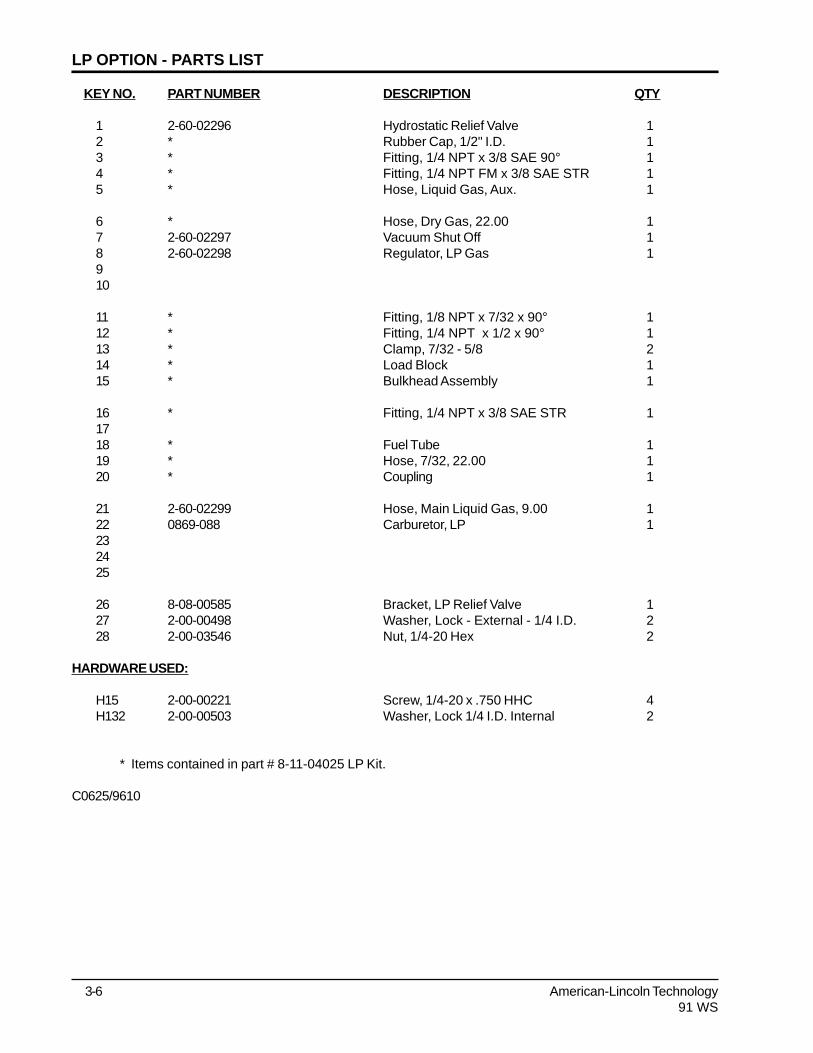
3-6 American-Lincoln Technology91 WS
KEY NO. PART NUMBER DESCRIPTION QTY
1 2-60-02296 Hydrostatic Relief Valve 12 * Rubber Cap, 1/2" I.D. 13 * Fitting, 1/4 NPT x 3/8 SAE 90° 14 * Fitting, 1/4 NPT FM x 3/8 SAE STR 15 * Hose, Liquid Gas, Aux. 1
6 * Hose, Dry Gas, 22.00 17 2-60-02297 Vacuum Shut Off 18 2-60-02298 Regulator, LP Gas 1910
11 * Fitting, 1/8 NPT x 7/32 x 90° 112 * Fitting, 1/4 NPT x 1/2 x 90° 113 * Clamp, 7/32 - 5/8 214 * Load Block 115 * Bulkhead Assembly 1
16 * Fitting, 1/4 NPT x 3/8 SAE STR 11718 * Fuel Tube 119 * Hose, 7/32, 22.00 120 * Coupling 1
21 2-60-02299 Hose, Main Liquid Gas, 9.00 122 0869-088 Carburetor, LP 1232425
26 8-08-00585 Bracket, LP Relief Valve 127 2-00-00498 Washer, Lock - External - 1/4 I.D. 228 2-00-03546 Nut, 1/4-20 Hex 2
HARDWARE USED:
H15 2-00-00221 Screw, 1/4-20 x .750 HHC 4H132 2-00-00503 Washer, Lock 1/4 I.D. Internal 2
* Items contained in part # 8-11-04025 LP Kit.
C0625/9610
LP OPTION - PARTS LIST

American-Lincoln Technology 3-791 WS
C0625/9610
EXISTING
ADAPTOR
TO FUEL
PUMP
REMOVE
EXISTING
CARBURETOR
AND REPLACE
WITH #22
H132
H150
22
18
14
12
13
13
11
7
8
20
3
15
H150
26
28
27
1
2
21
19
16
4
5
6
L/P TANK SUPPORT TO L/P TANK
CONNECTOR
LP OPTION - EXPLODED VIEW

3-8 American-Lincoln Technology91 WS
H153
H82
H48
C0626
FOAM FILLED TIRE OPTION
KEY NO. PART NUMBER DESCRIPTION QTY
1 0860-581 Wheel Assembly, Foam Filled 2
HARDWARE USED:
H48 2-00-00233 Screw, 3/8-16 x 1.000 HHC 2H82 2-00-00505 Lock Washer, 3/8 Int. Tooth 2H153 2-00-03266 Washer 2
C0626/0007

American-Lincoln Technology 3-991 WS
H170
C1168/9510
H169
WET SWEEP BYPASS OPTION
KEY NO. PART NUMBER DESCRIPTION QTY
1 8-16-07380 Cover, Impeller (Welded) 12 8-57-05026 Pivot, Valve 13 8-57-05027 Pivot, Valve (Threaded) 14 8-58-05790 Plate, Valve 15 7-13-07104 Clamp, Hose 1
6 8-16-00060 Control, Damper 17 8-16-07358 Cover, Rear 18 8-16-00061 Control, Damper Handle 19 8-18-00429 Decal 110 2-00-00491 Grommet 1
HARDWARE USED:
H169 2-00-02637 Screw, 1/4-20 x 2.750 HHC 3H170 2-00-03061 Screw, #10-24 x .500 THM 2
C1168/9510

3-10 American-Lincoln Technology91 WS
KEY NO. PART NUMBER DESCRIPTION QTY.
1 8-25-08205 Flap, Door 12 8-25-08204 Flap, Rear Outside 13 8-25-08206 Flap, R.H. Side 14 8-25-08207 Flap, L.H. Wheel Well 15 8-25-08208 Flap, Hopper 16 8-68-05085 Seal, Broom Door 17 8-68-05084 Seal, Broom Door 18 8-68-05073 Seal, Hopper 19 8-29-00231 Seal, Hopper 210 8-24-04074-1 Filter, Hopper 111 2-00-05284 Belt, Forward (3/4) 112 2-00-05285 Belt, Reverse (1/2) 113 2-00-05314 V-Belt, Main Broom Drive 114 2-00-01036 V-Belt, Main Broom Drive 115 2-00-05200 V-Belt, Impellor Drive 116 2-00-05286 V-Belt, Side Broom Drive 1
SPARE PARTS KIT - BATTERY MACHINE

American-Lincoln Technology 3-1191 WS
KEY NO. PART NUMBER DESCRIPTION QTY.
1 8-25-08205 Flap, Door 12 8-25-08204 Flap, Rear Outside 13 8-25-08206 Flap, R.H. Side 14 8-25-08207 Flap, L.H. Wheel Well 15 8-25-08208 Flap, Hopper 16 8-68-05085 Seal, Broom Door 17 8-68-05084 Seal, Broom Door 18 8-68-05073 Seal, Hopper 19 8-29-00231 Seal, Hopper 210 8-24-04074-1 Filter, Hopper 111 2-00-05284 Belt, Forward (3/4) 112 2-00-05285 Belt, Reverse (1/2) 113 2-00-05314 V-Belt, Main Broom Drive 114 2-00-01036 V-Belt, Main Broom Drive 115 2-00-05200 V-Belt, Impellor Drive 116 2-00-05286 V-Belt, Side Broom Drive 117 8-24-04143 Air Cleaner Element 118 8-24-04144 Fuel Filter 1
SPARE PARTS KIT - GAS MACHINE

BATTERY SCHEMATIC & CONNECTION DIAGRAM
C1188
CCCC24 VOLTBATTERY BANK
CB-210 AMP
CB-110 AMP
M1
30 87
SHAKER MOTOR
SHAKER MOTORRELAY
DRIVE
#1
TLH1 33X 2159
#3
#4
(G)(I)
#2
86 85
12 VOLT
SHAKERSWITCH
1A
1
4A 4A 7D,7E
7E
7C,7D
7A,7B
7B,7C
7C,7D4D,4E
4E 4C
4B,4C
2
7
7,7A
4B,4D
3
3
3B
3B
3C
3C 3A
A
1
1A
M1
MTR.
FU-170 AMP.
CM
20 SEC.TIMER
MTR.
PM
HM
OFF
MM
A
B
ON
KEY SW.
OFF
OFF
FILTERSHAKER CB-1CB-2
ON
M
M
A
B S
GI
BACK WIRING VIEWTOP
POWER PANEL
BOTTOM VIEWM1 RELAY
1 2 3 4
85
30
86
87
4A4A
4A
4A
7D
3C3A
2
7C7D
3
3B
7B
7C
4B4C
1
24E
4D
4E
7E
7
3
4B 7E 3B
3C4D
3A
M1
20 SEC.TIMER
70 A FUSE
SOLENOID 1A
(-) POST
(+) MOTOR LEAD
A
1
7
7A
7A4C
7B
(-) MOTORLEAD
RED BLK.SHAKERMOTOR
RED
FROMBATTERIES
TO (-) POSTTO BOTTOM70 A FUSE
RED
BLK.BLK.
American-Lincoln Technology®91WS
3-12

GAS SCHEMATIC & CONNECTION DIAGRAM
12V BATTERY
S STARTER MOTOR
SHAKER MOTOR
IGNITIONCOIL
10 AMPCHARGECOIL
REG.
SPARKPLUG
VM
HM
OFF
MM
A
(I) (G)B
ON
KEY SW.
BLK.
BLK.
BLK.
WHT
WHT
OFFCONNECT HERE
FOR OPTION
ON
REDWHT
WHT
RED(B+)
(B-)
BLK.
SHAKERSWITCH
20 SEC.TIMER
TLH1-33X-2159
OPTIONAL
#3
#1 #4
#2
M112 VOLT
SHAKER MTR.RELAY
86 85
STARTERSOLENOID
STARTERSOLENOID
STARTBUTTON
REDRED
OIL LEVELSWITCH
YEL
THROTTLEKILL SW.(STD.)
YEL
30
1A
1,1A5,5A
5A,5B 7B,7C
7D,7E
3
1
6
6
5B
2B
5B 4 4 7A
7,7E
7A,7B7A,7B
2
3A
2A,2B
2,2A
7C,7D
A
B
7
5
87
CB-210 AMP.
CB-110 AMP.
S
M1
MTR.
MTR.
L32
REDRED
OIL ALERT LIGHT SW.(STD.)
LOW OIL ALERT LIGHTSHUT DOWN
DISCONNECT LOW OIL ALERT LIGHT SWITCH,CONNECT WHT. TO WHT. & RED TO RED,USEONE 8-11-00015 TO CAP BLK. WIRE
OPTION
OFF
OFF
CHOKE
LOWOIL
FILTERSHAKER CB-1CB-2
START ON
M
M
A
B S
G
I
BACK WIRING VIEWTOP
BOTTOM VIEWM1 RELAY
8 HP B&SENG.
1 2 3 4
85
30
86
87
RED
RED
RED
A
B
7D
7E
57C
7D
6
2
2A55A
2A
2B
1
1A
1A
7A
3
4A
4A
4A
4A
3A
5B
1
2
7
7
6
3A
7E
7A 2B
7B
3
7B7C
5A
5B
GND.STUD
STARTSOL.
M1
20 SEC.TIMER
BATTERY
WHT.WIRE
RED BLK.SHAKERMOTOR
REG.
STARTERMOTOR
C1185
American-Lincoln Technology®91WS
3-13

3-14 American-Lincoln Technology91 WS
BATTERY .................................................................................................................................. 1-27BATTERY .................................................................................................................................. 2-22BATTERY CHARGING INSTRUCTIONS ................................................................................... 1-17BATTERY CONDITION METER (BATTERY ONLY).................................................................. 1-9BATTERY MACHINE OPERATION ........................................................................................... 1-14BATTERY POWERED MACHINES .......................................................................................... 1-6BATTERY POWERED SWEEPER, TO START THE .............................................................. 1-15BATTERY VOLT METER (GAS/LP ONLY) ................................................................................ 1-10BOLT IDENTIFICATION............................................................................................................. 1-37
CHANGING LP TANKS .............................................................................................................. 1-34CHOKE CONTROL (GAS/LP ONLY) ........................................................................................ 1-10CIRCUIT BREAKERS ............................................................................................................... 1-13CONTROL PANEL .................................................................................................................... 2-30COVERS ................................................................................................................................... 2-4
DECALS.................................................................................................................................... 2-34DECIMAL METRIC & CONVERSION TABLE ............................................................................ 1-36DRIVE SYSTEM ........................................................................................................................ 1-29DUST CONTROL ..................................................................................................................... 1-26
ELECTRICAL ASSEMBLY (BATTERY) ..................................................................................... 2-26ELECTRICAL ASSEMBLY (GAS) .............................................................................................. 2-28ENGINE ..................................................................................................................................... 2-24ENGINE AIR INTAKE ................................................................................................................. 1-28ENGINE OIL LEVEL, TO CHECK THE ..................................................................................... 1-29ENGINE WITH THE REWIND STARTER, TO START THE ..................................................... 1-16
FILTER BAFFLE, TO CLEAN THE............................................................................................ 1-26FILTER MANIFOLD LATCH ....................................................................................................... 1-12FILTER SHAKER ...................................................................................................................... 2-18FILTER SHAKER SWITCH ....................................................................................................... 1-10FLAPS ...................................................................................................................................... 1-27FOAM FILLED TIRE OPTION ................................................................................................... 3-8FORWARD/REVERSE CONTROL HANDLE ........................................................................... 1-12FRAME ...................................................................................................................................... 2-2FUEL FILTER ............................................................................................................................ 1-28FUEL TANK, TO FILL THE GASOLINE POWERED MACHINE ................................................ 1-18
GAS POWERED SWEEPER, TO START THE ....................................................................... 1-15GAS/LP MACHINE OPERATION ............................................................................................... 1-14GAS/LP POWERED MACHINES .............................................................................................. 1-5GASOLINE POWERED MACHINE FUELING INSTRUCTIONS................................................ 1-18
HARDWARE LEGEND.............................................................................................................. 1-39HOPPER ................................................................................................................................... 1-27HOPPER ................................................................................................................................... 2-16HOPPER DUMP HANDLE ........................................................................................................ 1-12HOPPER SEALS, TO CHECK THE ......................................................................................... 1-27HOPPER, TO CLEAN THE....................................................................................................... 1-27HOPPER, TO EMPTY............................................................................................................... 1-16
INDEX

American-Lincoln Technology 3-1591 WS
HOUR METER .......................................................................................................................... 1-9HOW TO SWEEP .................................................................................................................... 1-22
IMPELLER ................................................................................................................................. 2-20INDEX ...................................................................................................................................... 3-14
KEY SWITCH ............................................................................................................................ 1-9
LEFT HAND SIDE BROOM OPTION........................................................................................ 3-2LEGENDS - SCREW/SETSCREWS ....................................................................................... 1-38LOW OIL LIGHT (GAS/LP ONLY).............................................................................................. 1-10LOW OIL SHUTDOWN OPTION .............................................................................................. 3-4LOWER WHEEL DRIVE ........................................................................................................... 2-8LP CHECKLIST......................................................................................................................... 1-33LP FUEL TANKS ....................................................................................................................... 1-33LP GAS SYSTEM ...................................................................................................................... 1-32LP LIQUID WITHDRAWAL SYSTEM ......................................................................................... 1-32LP OPTION ............................................................................................................................... 3-6LP POWERED FUELING INSTRUCTIONS .............................................................................. 1-18LP POWERED SWEEPER, TO START THE ......................................................................... 1-15LP SAFETY PRECAUTIONS .................................................................................................... 1-31LP TANK, TO BEGIN CHANGING THE ..................................................................................... 1-34LP TANKS, TO CHANGE THE .................................................................................................. 1-19
MACHINE CONTROLS ............................................................................................................. 1-9MACHINE FOR TRANSPORT, TO DRIVE THE ........................................................................ 1-16MACHINE PREPARATION ........................................................................................................ 1-5MACHINE SPECIFICATIONS .................................................................................................... 1-3MACHINE STORAGE - BATTERY POWERED MACHINES ..................................................... 1-19MACHINE STORAGE - GASOLINE POWERED MACHINES ................................................... 1-19MAIN BROOM ........................................................................................................................... 1-23MAIN BROOM ........................................................................................................................... 2-10MAIN BROOM ADJUSTMENT ................................................................................................... 1-11MAIN BROOM ARMS ................................................................................................................ 2-12MAIN BROOM LEVER............................................................................................................... 1-1MAIN BROOM SWEEP HEIGHT, TO ADJUST THE.................................................................. 1-23MAIN BROOM SWEEP PATTERN, TO CHECK THE............................................................... 1-23MAIN BROOM, TO REPLACE THE .......................................................................................... 1-24MOTIVE POWERED BATTERIES (BATTERY ONLY), TO CHARGE THE .............................. 1-18
NEUTRAL SETTING, TO ADJUST............................................................................................. 1-29
OPERATING INSTRUCTIONS .................................................................................................. 1-14ORDERING PARTS .................................................................................................................. 1-42
PANEL FILTER, TO CHANGE THE ........................................................................................... 1-26PANEL FILTER, TO CLEAN THE .............................................................................................. 1-26POST OPERATION CHECKLIST ............................................................................................. 1-17PRE-START CHECKLIST......................................................................................................... 1-15
INDEX

3-16 American-Lincoln Technology91 WS
INDEXREPLACING THE FORWARD DRIVE BELT ............................................................................ 1-29REPLACING THE REVERSE BELT ......................................................................................... 1-30REWIND STARTER .................................................................................................................. 1-13RIGHT HAND SIDE BROOM .................................................................................................... 2-14
SAFETY PRECAUTIONS.......................................................................................................... 1-7SCHEMATIC & CONNECTION DIAGRAMS (BATTERY) .......................................................... 3-12SCHEMATIC & CONNECTION DIAGRAMS (GAS) ................................................................... 3-13SERVICE CHART ..................................................................................................................... 1-20SERVICE INSTRUCTIONS ....................................................................................................... 1-23SIDE BROOM ........................................................................................................................... 1-25SIDE BROOM LIFT HANDLE .................................................................................................... 1-11SIDE BROOM SWEEP HEIGHT, TO ADJUST THE ................................................................. 1-25SIDE BROOM SWEEP PATTERN, TO CHECK THE .............................................................. 1-25SIDE BROOMS, TO CHANGE THE ......................................................................................... 1-26SIDE FLAPS, TO ADJUST THE ................................................................................................ 1-27SPARE PARTS KIT (BATTERY) ............................................................................................... 3-10SPARE PARTS KIT (GAS) ........................................................................................................ 3-11STANDARD HARDWARE & TORQUE VALUES ...................................................................... 1-35START BUTTON (GAS/LP ONLY) ............................................................................................ 1-10STORAGE OF LP TANKS ........................................................................................................ 1-34SWEEPING GUIDELINES......................................................................................................... 1-22SWEEPING VARIOUS TYPES OF DEBRIS ............................................................................. 1-22
TABLE OF CONTENTS - CHAPTER 2 ..................................................................................... 2-1TABLE OF CONTENTS - CHAPTER 3 ..................................................................................... 3-1TO STOP SWEEPER .............................................................................................................. 1-16TO SWEEP WITH MACHINE .................................................................................................... 1-16
USE AND CARE OF LP TANKS................................................................................................ 1-34
WARRANTY .............................................................................................................................. 3-17WET SWEEP BYPASS OPTION.............................................................................................. 3-9WHEEL DRIVE.......................................................................................................................... 2-6

American-Lincoln Technology 3-1791 WS
AMERICAN-LINCOLN TECHNOLOGY91WS WALK BEHIND MACHINE
“BUMPER-TO-BUMPER” LIMITED WARRANTY
I. COVERAGEA. Subject to the terms and limitations stated herein, American-Lincoln warrants, to the original purchaser only, to repair or replace, at itsoption and upon the terms set out below, this product or any parts thereof (excluding normal maintenance items) which are defective inmaterials or workmanship, for a period of (1) one years or 1,000 hours of normal operation from the date of purchase, whichever comesfirst, but not to exceed (2) two years from the date of factory shipment, provided that the product is operated and maintained inaccordance with American-Lincoln’s Maintenance and Operations Instruction.
1. (a) During the first thirty (30) days from the date of purchase, American-Lincoln will provide, without charge, parts and on-site labor(including up to three(3) hours total round-trip travel time) to remedy a defective product or part.
(b) During the next six (6) months or 500 hours (whichever comes first) American-Lincoln will provide, without charge, parts toremedy a defective product or part; however, all labor, travel time for on-site remedy and all shipping and freight charges for off-siteremedy of the product or parts thereof shall be the sole responsibility of the purchaser.
B. In addition to the terms above (except as to the one year period), any original equipment American-Lincoln Battery which becomesunserviceable under normal use within a period of ninety (90) days from date of sale to the original user will be repaired or replaced withone of equal specifications at our option, F.O.B. any authorized American-Lincoln Sales or service branch, with no charge to the user,except transportation costs. After expiration of the above ninety (90) day period, any battery which fails under normal use will be adjustedto the original user with a new battery of equal specifications on an eighteen (18) months pro rate basis from the date of purchase.Adjustment will be determined using the then current list price, plus transportation costs. Warranty is rendered NULL and Void if batteryis not kept filled to the proper level with DISTILLED WATER.
C. In addition to the above, if applicable, American-Lincoln, warrants to the original purchaser only, to repair or replace, at its option andupon the terms set out below, the main frame, debris hopper, solution tank, and the recovery tank, for eight (8) years against failure causedby defects in workmanship or total rust through. For purposes of this coverage, cosmetic deterioration or surface rust does not constitutea failure.
II. EXCLUSIONSThis warranty does not cover normal maintenance parts and labor, including but not limited to, rubber parts, seals, flaps, brushes, enginemaintenance parts, hoses, carbon motor brushes, fluids and routine adjustments. This warranty does not cover damage or failure of theproduct or any parts thereof which is the result of misuse, negligent operation, handling or repair, or which is the result of modification byany person other than an authorized American-Lincoln service representative.
III. LIMITATIONSAMERICAN-LINCOLN MAKES NO WARRANTIES OTHER THAN THOSE SPECIFIED HEREIN. ALL IMPLIED WARRANTIES OF MERCHANTABIL-ITY AND OF FITNESS FOR A PARTICULAR PURPOSE ARE EXPRESSLY EXCLUDED. AMERICAN-LINCOLN LIABILITY UNDER THIS WAR-RANTY IS LIMITED TO REPAIR AND/OR REPLACEMENT OF PRODUCTS OR PARTS AS SET OUT HEREIN. AMERICAN-LINCOLN SHALL NOTBE LIABLE FOR ANY INCIDENTAL OF CONSEQUENTIAL DAMAGES WHICH MAY RESULT FROM A PRODUCT OR PART DEFECT ORFAILURE. ANY EXTENSIONS OF OR MODIFICATIONS MADE TO THIS WARRANTY BY A DISTRIBUTOR OF AMERICAN-LINCOLN ARE THESOLE RESPONSIBILITY OF THE DISTRIBUTOR.
IV. PROCEDURES AND CONDITIONS FOR WARRANTY CLAIMSAMERICAN-LINCOLN SHALL NOT BE LIABLE FOR REPAIR OR REPLACEMENT OF ANY DEFECTIVE PRODUCT OR PART THEREOF UNLESSAND UNTIL THE ORIGINAL PURCHASER FULFILLS THE FOLLOWING CONDITIONS PRECEDENT TO RECOVERY UNDER THIS WARRANTY:
1. The original purchaser shall promptly complete and return the warranty and installation registration form included with the product atthe time of the purchase.
2. Upon product or part failure, the original purchaser shall promptly provide notice thereof to his nearest authorized American-LincolnService Representative; and
3. The original purchaser shall permit the product or part to be inspected by American-Lincoln or its authorized representatives, asnecessary and expenses for shipping or travel time shall be borne by the parties itemized in paragraph I herein above.
American-Lincoln Technology reserves the right to make changes and improvements to its machines without notice. For best results, useonly the correct American-Lincoln Service parts.
AMERICAN-LINCOLN TECHNOLOGY1100 HASKINS ROAD
BOWLING GREEN, OHIO 43402


