[American Institute of Aeronautics and Astronautics 48th AIAA/ASME/ASCE/AHS/ASC Structures,...
6
American Institute of Aeronautics and Astronautics 1 Experimental study on etching method for fabricating cooling passages in combined-cycle-engine wall Toshihito Saito * and Shuichi Ueda † Combined Propulsion Research Group, Japan Aerospace Exploration Agency, Kakuda, Miyagi 981-1525, JAPAN Tsutomu Yamamura ‡ and Yuzuru Sato § Department of Metallurgy, Tohoku University, Aramaki Aoba-ku, Sendai, Miyagi 980-8579, JAPAN An etching method as a fabrication technique for cooling passages in a combined-cycle- engine wall was investigated. A nickel-based heatproof alloy, which is a candidate material for the walls of combined cycle engines, is hard, and machining of thin cooling passages in a large area is difficult. By the use of this etching method with photographic print, a large area can be easily processed at the same time. As this nickel-based heatproof alloy is also corrosion resistant, ferric chloride solution, a conventional etching solution, cannot be used for such etching. Thus, the authors chose an electrochemical technique for dissolving the nickel-based heatproof alloy and applied it for processing of the passages on the nickel-based heatproof alloy plate. In this experiment, the passages were carved on the entire surface of the plate, the size of which was 350mm x 220 mm. The passages at the edge of etched plate were observed to be deeper than those in the center area, and the ribs between passages at the edge were narrower than those in the center area. It was suggested that these phenomena occurred due to the uneven current distribution on the plate. Nomenclature E = potential I = electric current R = electric resistance I. Introduction N the case of scramjet-based combined-cycle engines operating up to a flight Mach number of 10, the heat flux received by the inner wall may reach an order of 10 6 W/m 2 . 1. Although that is one order lower than that of rocket engine combustors and rocket engine throats, the surface area of a scramjet engine is extremely large. This indicates that a material characterized by high strength and light weight should be employed for the wall structure of combined cycle engines, even if its thermal conductivity is relatively low. Application of a thin wall structure is efficacious in that it reduces the weight of the whole system. Durability at high temperature is also demanded of the material. Furthermore, it is necessary to embed cooling passages. For efficient use of the coolant, finer cooling passages should be employed, although these cooling passages must be of suitable size in light of the pressure drop of the coolant. In this study, nickel-based heatproof alloys were selected as candidates for use as wall materials. * Senior Researcher, Structure and Material Subgroup, Kakuda, Miyagi 981-1525, JAPAN, Member AIAA. † Head, Structure and Material Subgroup, Kakuda, Miyagi 981-1525, JAPAN, Member AIAA. ‡ Professor, Department of Metallurgy, Tohoku University, Sendai, Miyagi 980-8579, JAPAN, Non-member. § Professor, Department of Metallurgy, Tohoku University, Sendai, Miyagi 980-8579, JAPAN, Non-member. I 48th AIAA/ASME/ASCE/AHS/ASC Structures, Structural Dynamics, and Materials Conference<br>15th 23 - 26 April 2007, Honolulu, Hawaii AIAA 2007-2255 Copyright © 2007 by the American Institute of Aeronautics and Astronautics, Inc. All rights reserved.
Transcript of [American Institute of Aeronautics and Astronautics 48th AIAA/ASME/ASCE/AHS/ASC Structures,...

American Institute of Aeronautics and Astronautics
1
Experimental study on etching method for fabricating cooling passages in combined-cycle-engine wall
Toshihito Saito * and Shuichi Ueda † Combined Propulsion Research Group, Japan Aerospace Exploration Agency, Kakuda, Miyagi 981-1525, JAPAN
Tsutomu Yamamura ‡ and Yuzuru Sato §
Department of Metallurgy, Tohoku University, Aramaki Aoba-ku, Sendai, Miyagi 980-8579, JAPAN
An etching method as a fabrication technique for cooling passages in a combined-cycle-engine wall was investigated. A nickel-based heatproof alloy, which is a candidate material for the walls of combined cycle engines, is hard, and machining of thin cooling passages in a large area is difficult. By the use of this etching method with photographic print, a large area can be easily processed at the same time. As this nickel-based heatproof alloy is also corrosion resistant, ferric chloride solution, a conventional etching solution, cannot be used for such etching. Thus, the authors chose an electrochemical technique for dissolving the nickel-based heatproof alloy and applied it for processing of the passages on the nickel-based heatproof alloy plate. In this experiment, the passages were carved on the entire surface of the plate, the size of which was 350mm x 220 mm. The passages at the edge of etched plate were observed to be deeper than those in the center area, and the ribs between passages at the edge were narrower than those in the center area. It was suggested that these phenomena occurred due to the uneven current distribution on the plate.
Nomenclature E = potential I = electric current R = electric resistance
I. Introduction N the case of scramjet-based combined-cycle engines operating up to a flight Mach number of 10, the heat flux received by the inner wall may reach an order of 106 W/m2. 1. Although that is one order lower than that of rocket
engine combustors and rocket engine throats, the surface area of a scramjet engine is extremely large. This indicates that a material characterized by high strength and light weight should be employed for the wall structure of combined cycle engines, even if its thermal conductivity is relatively low. Application of a thin wall structure is efficacious in that it reduces the weight of the whole system. Durability at high temperature is also demanded of the material. Furthermore, it is necessary to embed cooling passages. For efficient use of the coolant, finer cooling passages should be employed, although these cooling passages must be of suitable size in light of the pressure drop of the coolant. In this study, nickel-based heatproof alloys were selected as candidates for use as wall materials.
* Senior Researcher, Structure and Material Subgroup, Kakuda, Miyagi 981-1525, JAPAN, Member AIAA. † Head, Structure and Material Subgroup, Kakuda, Miyagi 981-1525, JAPAN, Member AIAA. ‡ Professor, Department of Metallurgy, Tohoku University, Sendai, Miyagi 980-8579, JAPAN, Non-member. § Professor, Department of Metallurgy, Tohoku University, Sendai, Miyagi 980-8579, JAPAN, Non-member.
I
48th AIAA/ASME/ASCE/AHS/ASC Structures, Structural Dynamics, and Materials Conference<br> 15th23 - 26 April 2007, Honolulu, Hawaii
AIAA 2007-2255
Copyright © 2007 by the American Institute of Aeronautics and Astronautics, Inc. All rights reserved.
American Institute of Aeronautics and Astronautics
2
Nickel-based heatproof alloys are hard, and machining of thin cooling passages in the large area of the wall is both time-consuming and costly. By the use of a chemical etching method, however, a large area can be easily processed at the same time. Furthermore, using a photographic print covering a large area, uniform cooling passage processing can be performed by controlling the pattern of etching. A merit of this method is that the etching pattern arrangement is highly flexible.
As for the structure of a cooling wall made of a nickel heatproof alloy by this method, its applicability to other engines and heat exchangers can be expected.
II. Photo-etching method An etching method with a photographic print is
carried out as follows. First, a masked pattern is created. The pattern is determined based on the design of the cooling passages. The pattern is placed on a plate to which a sensitization agent is applied, and printed by developing light, resulting in creation of the pattern on the plate. The plate is then etched to a predetermined depth. Finally, the film is removed and the etching ends.
Conventionally, etching has been mainly used with thin plates, and there are many examples of its application to stainless steel. In a previous study,2 cooling structure plates were fabricated from stainless steel as follows. Passages were fabricated on the stainless plates by etching, and covering plates were brazed on them. These were cooling panels. The duct-shaped cooling structure consisted of four cooling panels simulating the engine inner wall. It was heated by combustion gas flow and was cooled by liquid hydrogen. Although stainless steel was employed for the cooling panels in the previous study, nickel-based heatproof alloys are superior to stainless steel from the viewpoint of strength and ability to withstand high temperatures. Etching has seldom been employed for processing of nickel-based heatproof alloys, especially alloys containing molybdenum, because conventional etching solution (ferric chloride solution) cannot be used for dissolving such alloys. Figure 1 shows the degree of dissolution of stainless steel and typical nickel alloys in the ferric chloride solution with time. Table 1 shows the composition of these alloys. The dissolution speed of nickel alloy A was slow compared with that of stainless steel to which etching was applied. In addition, nickel alloy B was
-0.15
-0.10
-0.05
0.00
0.05
0 60 120 180 240 300 360 420
Stainless steelNickel Alloy ANickel Alloy B
Wei
ght l
oss (
g/cm
2 )
Time (min.)
Figure 1 Weight loss for each unit area of the alloys in the ferric chloride solution.
Table 1 Composition of the alloys Fe Cr Ni Mn Mo Co WStainless steel A 70 16 10 2 2 Nickel alloy A 6 14 80 Nickel alloy B 18 22 48.9 9 1.5 0.6
Electrolyte
Working electrode = Alloy B
Counter electrode
Reference electrode
Bridge
Potentiostat
Function generator
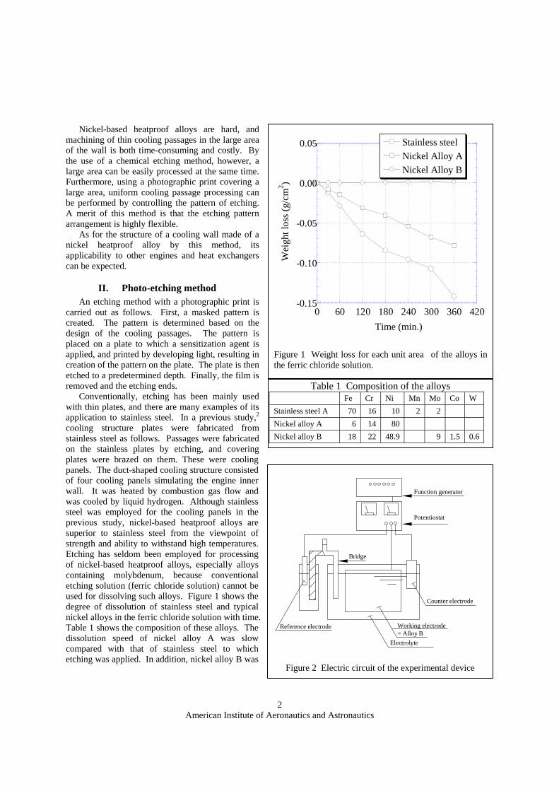
Figure 2 Electric circuit of the experimental device
American Institute of Aeronautics and Astronautics
3
not dissolved. This shows that alloy B cannot be etched with ferric chloride solution.
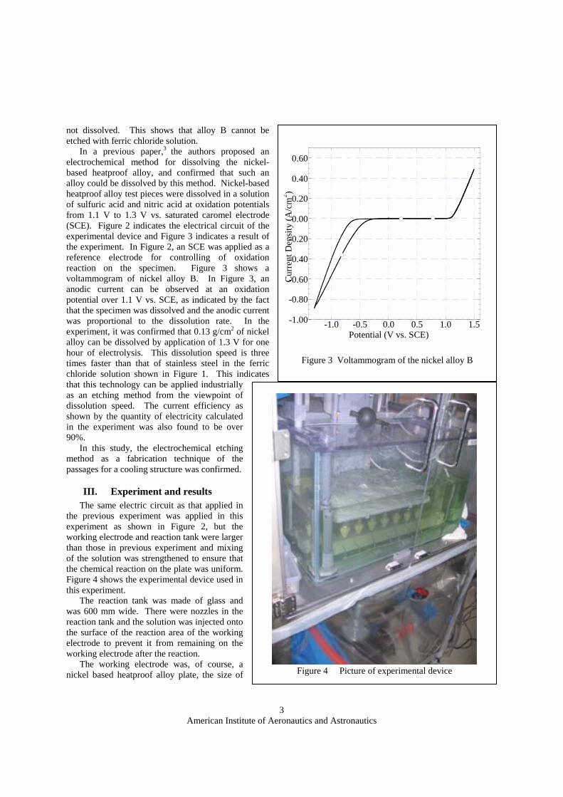
In a previous paper,3 the authors proposed an electrochemical method for dissolving the nickel-based heatproof alloy, and confirmed that such an alloy could be dissolved by this method. Nickel-based heatproof alloy test pieces were dissolved in a solution of sulfuric acid and nitric acid at oxidation potentials from 1.1 V to 1.3 V vs. saturated caromel electrode (SCE). Figure 2 indicates the electrical circuit of the experimental device and Figure 3 indicates a result of the experiment. In Figure 2, an SCE was applied as a reference electrode for controlling of oxidation reaction on the specimen. Figure 3 shows a voltammogram of nickel alloy B. In Figure 3, an anodic current can be observed at an oxidation potential over 1.1 V vs. SCE, as indicated by the fact that the specimen was dissolved and the anodic current was proportional to the dissolution rate. In the experiment, it was confirmed that 0.13 g/cm2 of nickel alloy can be dissolved by application of 1.3 V for one hour of electrolysis. This dissolution speed is three times faster than that of stainless steel in the ferric chloride solution shown in Figure 1. This indicates that this technology can be applied industrially as an etching method from the viewpoint of dissolution speed. The current efficiency as shown by the quantity of electricity calculated in the experiment was also found to be over 90%.
In this study, the electrochemical etching method as a fabrication technique of the passages for a cooling structure was confirmed.
III. Experiment and results The same electric circuit as that applied in
the previous experiment was applied in this experiment as shown in Figure 2, but the working electrode and reaction tank were larger than those in previous experiment and mixing of the solution was strengthened to ensure that the chemical reaction on the plate was uniform. Figure 4 shows the experimental device used in this experiment.
The reaction tank was made of glass and was 600 mm wide. There were nozzles in the reaction tank and the solution was injected onto the surface of the reaction area of the working electrode to prevent it from remaining on the working electrode after the reaction.
The working electrode was, of course, a nickel based heatproof alloy plate, the size of
-1.00
-0.80
-0.60
-0.40
-0.20
0.00
0.20
0.40
0.60
-1.0 -0.5 0.0 0.5 1.0 1.5
Cur
rent
Den
sity
(A/c
m2 )
Potential (V vs. SCE)
Figure 3 Voltammogram of the nickel alloy B
Figure 4 Picture of experimental device

American Institute of Aeronautics and Astronautics
4
which was 350 mm x 220 mm and whose reaction area was 250.4 mm x 114.4 mm. A mask was printed on the plate and its pattern was designed for creating cooling passages. Slits 0.2 mm in width were laid with 2.2-mm pitches on the mask. There were 4 coolant-supplying-and-exiting areas on the plate. The mask was a film made of an acrylic resin.
The reference electrode was an SCE. The counter electrode was platinum wire. The current was controlled to maintain a constant oxidation potential of the working electrode. An HA-310 potentiostat from Hokuto Denko Corporation, Tokyo was used to supply electricity.
In the first experiment, the counter electrode was set in the corner in the reaction tank. However, the dissolution reaction on the plate occurred only near the counter electrode and a hole opened in the plate. There was a portion of the plate to which current flowed most easily and most current flowed there.
In the next experiment, a ladder-shaped counter electrode was mounted face to face with the working electrode to prevent the dissolution reaction in a limited area. The working electrode was reciprocated over the counter electrode in the etching solution, and the distance from the counter electrode became almost equal from the view point of time average, anywhere in the reaction area on the working electrode.
The etching solution was a mix solution of sulfuric acid and nitric acid. Mass was calculated from the volume of the passages etched into the plate, and the quantity of the electricity
needed for the etching was calculated from the mass. In the previous study, approximately 5400 C of quantity of the electricity was needed for dissolving 1 g of alloy.
Figure 5 is a picture of the plate after etching. The passages were etched into the entire plate as shown in this figure. Figure 6 shows details of the three-dimensional shape of the passages, and Figure 7 shows a cross-section of
Figure 5 Picture of the plate
Figure 6 3D image of the passages of the part of the plate

American Institute of Aeronautics and Astronautics
5
the passages. These data were obtained by an LT-9030M laser displacement sensor and a highly accurate KS-1100 shape measurement stage from Keyence Corporation, Osaka. These figures indicate that the passages at the edge were deeper than those in the center area and that the ribs between passages at the edge were narrower than those at in the center area.
IV. Analytical study of oxidation potential distribution of etching solution The etching solution in the reaction tank was mixed well, so both the concentration of the solute and the
temperature of the solution were uniform. This indicates that the electric resistance of the solution was constant in the reaction tank. Based on this fact, the authors attempted to simply simulate oxidation potential distribution of the etching solution in the reaction tank. The electric current flowed in the etching solution was in proportion to the potential difference and in inverse proportion to the electric resistance.
REi ∆
= (1)
At a certain point in the reaction tank, the electric current which flows in and that which flows out are equal. For the two-dimensional area, as electric resistance was constant, this fact could be expressed by the following equation;
0=∂∂
+∂∂
+∂∂
+∂∂
∆+=∆−=∆+=∆−= yyyyyyxxxxxx yE
yE
xE
xE
(2).
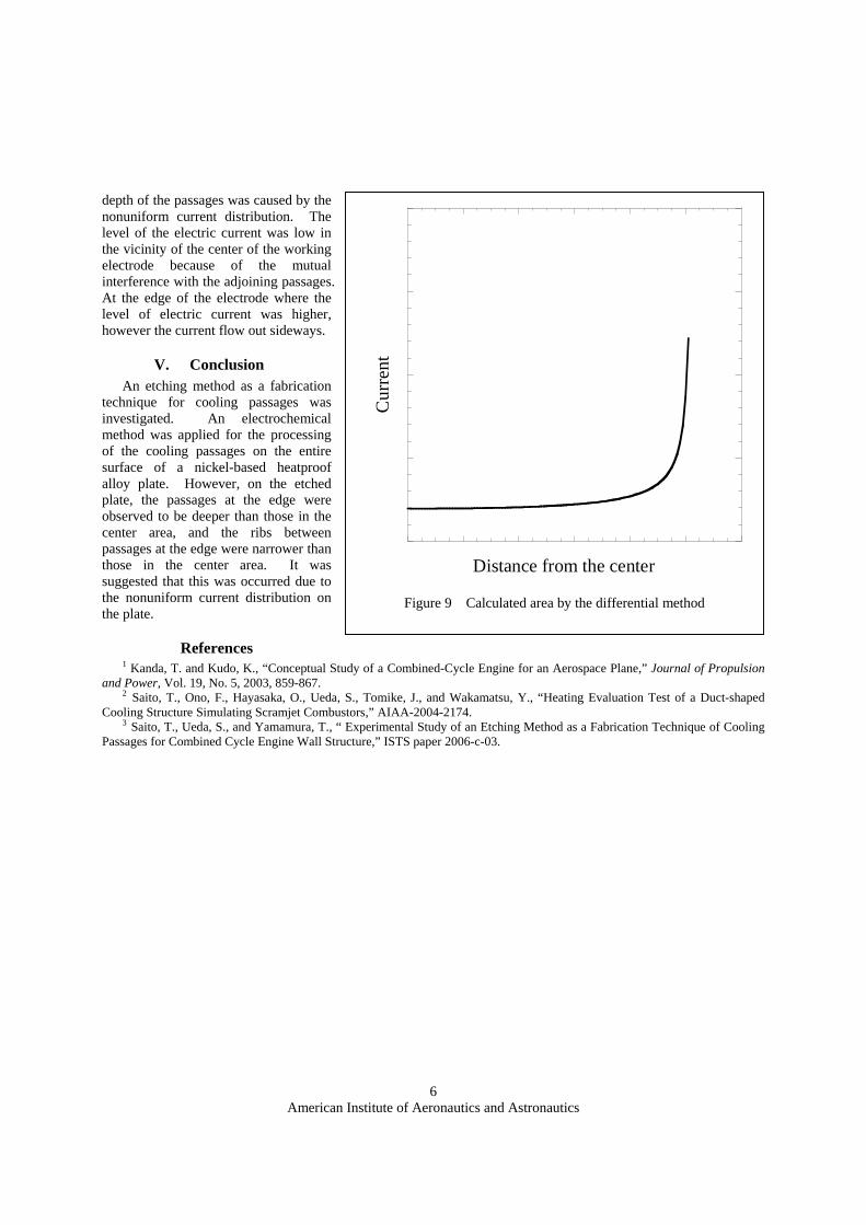
The differential method was applied to this equation, and two-dimensional oxidation potential of the etching solution was calculated. The calculated area is shown in Figure 8, and the potential of the counter electrode and that of the working electrode are given respectively. For the calculation, these electrodes were positioned as shown Figure 8 based on the experiment. The electric current at a certain point was in proportion to the potential difference with the adjoining point of contact. The distribution of the electric current on the working electrode was calculated based on the potential difference and is shown in Figure 9. The electric current that flowed out from the edge of the working electrode was larger than that flowed out from the vicinity of the center of the working electrode. This tendency with greater electric current on the edge of the working electrode corresponded to the tendency to the depth of the passages, and nonuniformity of the
reaction surfaceworking electrode (plate)
counter electrode
reaction tank
etching solution
Figure 8 Calculated area by the differential method
-1.0-0.50.0
0 5 10 15
deep
ness
(mm
)
distance (mm)
Figure 7 Cross section of the passages
American Institute of Aeronautics and Astronautics
6
depth of the passages was caused by the nonuniform current distribution. The level of the electric current was low in the vicinity of the center of the working electrode because of the mutual interference with the adjoining passages. At the edge of the electrode where the level of electric current was higher, however the current flow out sideways.
V. Conclusion An etching method as a fabrication
technique for cooling passages was investigated. An electrochemical method was applied for the processing of the cooling passages on the entire surface of a nickel-based heatproof alloy plate. However, on the etched plate, the passages at the edge were observed to be deeper than those in the center area, and the ribs between passages at the edge were narrower than those in the center area. It was suggested that this was occurred due to the nonuniform current distribution on the plate.
References 1 Kanda, T. and Kudo, K., “Conceptual Study of a Combined-Cycle Engine for an Aerospace Plane,” Journal of Propulsion
and Power, Vol. 19, No. 5, 2003, 859-867. 2 Saito, T., Ono, F., Hayasaka, O., Ueda, S., Tomike, J., and Wakamatsu, Y., “Heating Evaluation Test of a Duct-shaped
Cooling Structure Simulating Scramjet Combustors,” AIAA-2004-2174. 3 Saito, T., Ueda, S., and Yamamura, T., “ Experimental Study of an Etching Method as a Fabrication Technique of Cooling
Passages for Combined Cycle Engine Wall Structure,” ISTS paper 2006-c-03.
Cur
rent
Distance from the center
Figure 9 Calculated area by the differential method