American Flyer SD70ACe Diesel Locomotive Owner’s …€¦ · American Flyer SD70ACe Diesel...
36
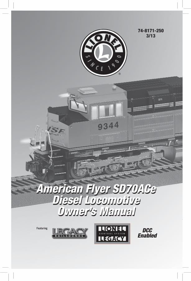
Featuring 74-8171-250 3/13 American Flyer SD70ACe Diesel Locomotive Owner’s Manual American Flyer SD70ACe Diesel Locomotive Owner’s Manual DCC Enabled DCC Enabled
Transcript of American Flyer SD70ACe Diesel Locomotive Owner’s …€¦ · American Flyer SD70ACe Diesel...
Featuring
74-8171-2503/13
American Flyer SD70ACeDiesel LocomotiveOwner’s Manual
American Flyer SD70ACeDiesel LocomotiveOwner’s Manual
DCC Enabled
DCC Enabled

2
Congratulations!
Congratulations on your purchase of this American Flyer LEGACY diesel locomotive! On the outside, this locomotive features numerous details and expert decoration in your favorite livery.
Inside the body, this locomotive is equipped with some of the most advanced sounds and controls in model railroading. This powerful locomotive is ready for duty on your layout.
Included with your locomotive1 Powered locomotive
4 Replacement traction tires
1 Owner's manual
2 Scale coupler mounting brackets and screws
1 Smoke fluid funnel
The following Lionel marks are used throughout this Owner’s Manual and are protected under law. All rights reserved.
Lionel®, LEGACY™, FasTrack®, TrainMaster®, Odyssey®, RailSounds®, CrewTalk™, TowerCom™, DynaChuff™, StationSounds™, Pullmor®, ElectroCoupler™, Magne-Traction®, CAB-1® Remote Controller, American Flyer®, Lionel ZW®, ZW®, MagniVision®, TMCC®, Lionelville®, Wireless Tether™, Powerhouse™, LionMaster®, Conventional Classics™, Postwar Celebration Series™, TruRail™, PH-1 Powerhouse®, Powermaster®, Powerstation-Powerhouse®, Accessory Motor Controller™, AMC™, Accessory Switch Controller™, ASC™, Action Recorder Controller™, ARC™, Track Power Controller 300™, TPC 300™, Track Power Controller 400™, TPC 400™, Block Power Controller™, BPC™, Operating Track Controller™, OTC™, FatBoy™, Lionel Lines®, Joshua Lionel Cowen Series™, Lockon®, TrainSounds™, MultiHorn™, MultiWhistle™, Choo-Choo™
DCC On Board is a Registered Trademark of Bachmann Industries, Inc. All Rights Reserved.
Digitrax is a Registered Trademark of Digitrax, Inc. All Rights Reserved.

3
Table of contentsRunning your locomotiveLocomotive basics 4LEGACY Control operations 5TrainMaster Command Control (TMCC/Command) operations 6Conventional transformer operations 7
Locomotive basicsAdding smoke fluid to your locomotive's smoke generator 8Locomotive switch locations 9Assigning your locomotive a new ID# (LEGACY and TMCC) 10Lash-ups (for LEGACY operations only) 11
LEGACY Control System operations The LEGACY CAB-2 Remote Controller 12The Velocity Throttle 13The Multi-Controller 13The Train Brake Slider 13The Warning Sound Controller 14The Speed Bar 14EFX Trim and EFX Bar Graph 15Leaving the Preset Speed Screen 15
LEGACY RailSounds sound system operations LEGACY RailSounds sound system 16LEGACY RailSounds Sequence Control 17CrewTalk dialog and TowerCom announcements in the LEGACY environment 18
TrainMaster Command Control operationsCAB-1 Remote Controller commands 19CAB-1 Remote Controller numeric keypad commands 20-21Controlling the smoke level and cab lights 21
Conventional transformer operationsUsing the LEGACY RailSounds sound system in the conventional environment 22Activating CrewTalk dialog and TowerCom announcements 22Locking your locomotive into a single direction 23
DCC operationsDC and DCC operation 24DCC Mode Operating Features 25Setting the locomotive address in DCC mode 25Setting the consist position (CV50) in DCC mode 25Lionel Specific CV settings 26-27
Maintaining and servicing your locomotiveReprogramming your locomotive to restore features (LEGACY) 28Reprogramming your locomotive to restore features (TMCC) 29Installing your scale couplers (not included) 30Lubricating your locomotive 31Servicing your locomotive’s LEDs 32Replacing the traction tires 33Locomotive diagnostics 34Notes 35Lionel Limited Warranty Policy & Service 36

4
Powering your locomotive in excess of 19 volts, may result in damage to sensitive electronic components.
Your locomotive requires curves that have a 36" or larger diameter, measured from center point between rails to center point between rails.
Note!
Note!
Running your locomotive
Locomotive basics
Your Locomotive is equipped with the latest generation electronics for operation in AC, TMCC, DC, and DCC environments. Additionally, scale wheels and couplers are supported
for the discriminating modeler.When placing the locomotive on the track, several startup checks are performed. The
locomotive will sample the track voltage for AC or DC power, and then look for any DCC or TMCC control signals. The DCC control signal has priority over the TMCC signal, so layouts that have both TMCC and DCC will operate properly, in that the track the locomotive is on will drive the operational features.
Several DCC command systems were tested, and listed below. The Configuration Variables (CVs) are programmable in all modes (Ops, Page, Direct, and Register). In many cases, reading back the CVs on a programming track are inconsistent; the only exception is the NCE Power Cab system, which works fine. In other DCC command systems, the CV reading is quite reliable when using the DCC Specialties PowerPax™ Booster.
DCC Systems Tested with the Lionel DCC decoder:
NCE Power Cab™
Digitrax DCS50™
Digitrax DCS51™
MRC Prodigy Advance 2 ™
DCC Specialties contact information:DCC Specialties57 River Rd, Suite 1023Essex Junction, VT 05452800-671-0641email: [email protected]

5
1. Turn off track power, and then plug in the LEGACY Base and connect it to the track.
2. Place your locomotive on the track.
3. Increase track power voltage to full power (no more than 19 volts AC). If a circuit breaker trips when you turn on the Lionel power supply, check the wheels of your locomotive to make sure they are all securely on the track. Check to make sure the track is free of all metals that may cause a short circuit.
4. As illustrated in Figure 1, press ENG and 1 (or your selected ENG ID#) to address the locomotive with your LEGACY CAB-2 Remote Controller.
5. Press the Start Up button on your LEGACY CAB-2 Remote, shown in Figure 2. Then, throttle up and move 'em out! Your engine sound will start up, and the locomotive-specific touch screen buttons will populate the remote. For more information on operating your locomotive with the LEGACY system, please refer to the LEGACY section of this manual. Additional information is also found in the LEGACY System Manual, available online at www.lionel.com.
Running your locomotive
Figure 1. LEGACY engine selection
Figure 2. Start up button
LEGACY Control operations
For the finest operating experience, your locomotive is fully compatible with the LEGACY Control System. To operate in LEGACY mode, you need a LEGACY Command Base and LEGACY CAB-2
Remote Controller (6-14295). Your commands are sent by the CAB-2 Remote Controller to the Command Base, which sends
a digital code through the rails to your locomotive. Your locomotive will not respond until it recognizes its unique ID#, so you can operate multiple Command-equipped locomotives on the same track at the same time.
Powering your locomotive in excess of 19 volts, may result in damage to sensitive electronic components.
Your locomotive requires curves that have a 36" or larger diameter, measured from center point between rails to center point between rails.
Note!
Note!

6
Running your locomotive Powering your locomotive in excess of 19 volts, may result in damage to sensitive
electronic components.
Your locomotive requires curves that have a 36" or larger diameter, measured from center point between rails to center point between rails.
TrainMaster Command Control (TMCC) operations
For operation in the TrainMaster Command Control environment, you need a TrainMaster Command Base (6-12911) and a CAB-1 Remote Controller (6-12868). Refer to your TMCC
System Manual for complete information. To access all the locomotive's features, you must operate in the LEGACY environment, as discussed on the previous page.
Your commands are sent by the CAB-1 Remote Controller to the Command Base, which translates the command into digital code. That code is sent through the outside rails to your locomotive, which will not respond until it recognizes its unique ID#. TrainMaster Command Control gives you the power to operate multiple Command-equipped locomotives on the same track at the same time.
1. Turn off track power, and then plug in the Command Base and connect it to the track.
2. Place your locomotive on the track.
3. Increase track voltage to full power (no more than 19 volts AC). If a circuit breaker trips when you turn on the Lionel power supply, check the wheels of your locomotive to make sure they are all securely on the track. Check to make sure the track is free of all metals that may cause a short circuit.
4. Press ENG and 1 (or the ENG ID# you set) to address your locomotive with your CAB-1 Remote Controller.
5. Throttle up and move ‘em out. For more information, please refer to the TrainMaster Command Control operations section of
this manual or the TMCC System Manual, available online at www.lionel.com.
Note!
Note!

7
Running your locomotiveConventional transformer operations
For Conventional operation, a Command Base must not be powered up anywhere in the area, even if it is not connected to the track. If a base is detected, your locomotive will default to Command mode.
Powering your locomotive in excess of 19 volts, may result in damage to sensitive electronic components.
Your locomotive requires curves that have a 36" or larger diameter, measured from center point between rails to center point between rails.
When operating in the Conventional environment, set the smoke unit switch to the Off position if you will be making multiple direction changes to prevent overheating the smoke unit. See Figure 4 on page 9 for the location of this switch.
1. With track power off, place your locomotive on the track. 2. Power up the track (8-18 volts AC). Starting voltage will vary based on the
locomotive's load. If a circuit breaker trips when you turn on the Lionel power supply, check the wheels of your locomotive to make sure they are all securely on the track. Check to make sure the track is free of all metals that may cause a short circuit.
3. Move ‘em out! When the locomotive’s headlight illuminates and the LEGACY RailSounds sound system starts, press the DIRECTION button on your transformer to sequence your locomotive through the repeating pattern of operations: neutral, forward, neutral, reverse, neutral, and so on. You may also briefly turn off track power to advance the locomotive to the next operating state. Adjust the throttle until your locomotive moves at your desired speed.
When placing your locomotive on your layout for the first time and after power interruptions lasting longer than five seconds, it will start out in neutral.
Use the HORN and BELL buttons on your transformer to activate those features. Adjust the volume using the volume control knob. Refer to Figure 4 on page 9 for the location of this control. For more information, please refer to the Conventional transformer operations section of this manual.
If the HORN and BELL buttons on your transformer appear to be reversed (i.e., trigger the other sound), simply switch the wire connections at the transformer terminals.
Note!
Note!
Note!
Note!
Note!
Caution!

8
Locomotive basics
Your locomotive is equipped with a smoke generator that produces safe, clean, white smoke during operation. Add 10-20 drops to the duct (shown in Figure 3) to prime the unit the first
time you run the locomotive or after being stored for an extended period of time, and then add 10 to 20 drops to refill when smoke production decreases. When refilling, DO NOT EXCEED 20 DROPS as this can cause your smoke unit to become oversaturated allowing leakage onto the electronics. Note that operating your locomotive's smoke unit without smoke fluid will cause damage to the heating element.
If you prefer to operate your locomotive without smoke, locate the smoke unit switch and slide it to the NO SMK position. Refer to Figure 4 on page 9 for the location of the switch.
For best performance, we recommend using Lionel smoke fluid only.
You may find it helpful to add smoke fluid using the funnel that is packed with this locomotive.
Adding smoke fluid to your locomotive’s smoke generator
Figure 3. Smoke fluid location
Note!
Note!
Exhaust stack. Remove cover.
Add smoke fluid here.
REAR

9
NO S
MK
SMK
PGM
RUN
VOL
The functions of your locomotive's switches are outlined below. Refer to Figure 4 for the location of the switches. The instructions below are specific to this particular locomo-
tive; note that available features (and switches) may differ from other loco-motives and locomotive sets.
Smoke Unit Switch (SMK/NO SMK)Used to turn the smoke unit function on and off. Be sure that track power is off when you throw
the switch
Program-Run Switch (RUN/PGM)Used to assign an ID# and to reprogram the locomotive for LEGACY and Command operation
when the switch is in the PGM position. Also used to “lock” your powered locomotive in a single direction, or neutral, in conventional operation when the switch is placed in the PGM position.
Figure 4. Locomotive switch locations
Smoke unit switch
Locomotive basicsLocomotive switch locations
Program-Run switch
Volume control knob
Remove rooftop hatchREAR

10
For operation in the LEGACY or TMCC environment, you will want to give each unit a unique ID#. The locomotive will respond to commands associated with its ID# while all other units will
disregard these commands. This procedure is not necessary for conventional (non-Command) operation.
1. Slide the Program-Run switch on your locomotive to the PGM position. See Figure 4 on page 8.
2. Place the locomotive on the track.
3. Connect the Command Base and plug it in.
4. Power up the track.
5. Press ENG on the CAB-1 or CAB-2 remote.
6. Enter the unique ID#. Choose any number from 1 to 98 that has not been assigned to another locomotive (ENG). We recommend using a part of your locomotive’s road number.
All LEGACY locomotives respond to ENG 99. We recommend that you reserve ID# 99 as a "universal" ID#.
7. Press SET. The locomotive's headlights will flash. The horn will also sound provided that the overall volume of the RailSounds has not been lowered.
8. Slide the Program-Run switch back to the RUN position.The locomotive’s ID# has been set. Be sure to record the new ID# for your reference.
Locomotive basicsAssigning your locomotive a new ID# (LEGACY and TMCC)
Note!

11
Locomotive basicsLash-ups (for LEGACY operations only)
In the Command environment, building a lash-up allows you to control your locomotive as one in a prototypical manner. It is still possible to control any of the engines in the lash-up
individually. When you issue a train command, the individual engine you were controlling will return to the group.
To build a lash-up, assign a unique engine (ENG) ID# to each unit. See page 9 for details.
1. Address the train ID# you wish to create or edit, 1 to 99.
2. Press INFO.3. Press BUILD softkey (button directly under
BUILD).4. Enter the front engine number. It is not
necessary to enter ENG, just enter the #. It will appear in the blinking box.
5. Press ADD to add the front engine. The engine will move to the right and the blinking box will be ready for your next engine to be added.
6. Enter the second engine ID# in the blinking box.7. Press ADD to add the second engine. The engine
will move to the right and the blinking box will be ready for your next engine to be added.
8. Add all the engines you want in your lash-up in this manner.
9. To change the direction of an engine in your lash-up, turn the Velocity Throttle to move the engine you want into the blinking box. Then press DIR to change the direction of the engine.
10. To delete an engine in your lash-up, turn the red Velocity Throttle knob to move the engine you want to delete into the blinking box. Then press DEL.
11. To save your lash-up, press SET. Watch the onscreen prompts and wait until you see the message TRAIN CREATED.
12. Press CTC to exit to the operating screen.
See reference numbers 1 and 2
See reference number 4
See reference number 3
See reference numbers 6 and 7

12
LEGACY Control System operationsThe LEGACY CAB-2 Remote Controller
Main DisplayDisplays real-time information about your railroad system. Displays real-time feedback of operation.
Scroll ButtonNavigates through the entire list of Engines, Trains, Switches, etc.
Select ButtonPerforms addressing by 3-4 digit road number.
Touch Screen Key PadA group of touch sensitive keys with icons for each function. These keys serve many purposes and their icons change accordingly.Train Brake SliderThis slider is used to increase or decrease the amount of Train Brake affecting the engine or train.
Train Link ButtonQuick select of Train-Link devices (LEGACY Control System Version 1.3)
AUX-2/Out ButtonControls switch direction.Toggles all directional lights on/off.
Emergency Halt ButtonStops everything on layout; also stops recording playback.
Record ButtonUsed to record and play back events.
Velocity ThrottleThrottle control over engines, also used to navigate thru info/options.
Set ButtonUsed to set Engine address and for programming.
Info ButtonUsed to enter/view the info/options of
selected components.
CTC ButtonPress and hold to turn your remote on and off. Tap this button to enter
the remote and base options. Tap it again to return to the main
screen.
Soft KeysThese keys directly correlate to the
5 selection boxes located at the bottom of the main display. These
are also used in the info/option menus to select options.
Warning Sound ControllerWarning Bell and Variable Horn
control. Pull down to sound Horn. Push up and release to trigger
Warning Bell.
Official R.R. Speed Control BarToggles the touchscreen display of
R.R. preset speeds and control panel.
Multi ControllerBoost, Brake, and Direction
control. Rock forward for Boost, rock backward for engine brake,
and press down for direction change. Click-hold-and rock for
absolute direction selection.
Front & Rear Coupler ButtonsFire couplers.
Low, Medium, High Momentum ButtonsUsed to select the desired momentum of
your addressed engine/train/accessory.
AUX-1/Thru ButtonPress to view the Control Panel while operating. Controls switch direction.
Feedback ButtonToggle ON/OFF the vibration feedback
feature in the CAB-2 Remote.

13
The Velocity Throttle (the red rotary knob on the bottom of your Lionel remote) is used to start your engine moving, slow it down, or speed it up. Use it simply by turning it clockwise (speed up) or counter-clockwise (slow down).
DirectionThe direction of your engine toggles between forward and reverse at the
touch of the Multi-Controller. Press the center of the Multi-Controller once, and your engine's lights will change directions and the engine will stop until you throttle up again in the new direction.
Boost & BrakeBoost and brake give you another way to control the speed of your train.
Boost gives your loco a temporary increase in tractive power, and returns to the previous speed when you release the control, while the brake command slows you down more quickly than the Velocity Throttle alone.
LEGACY Control System operations
The Velocity Throttle
The Multi-Controller
The Train Brake is used to slow down and limit the top speed of your train by adding a load. The more the Train Brake is applied by pulling the Train Brake Slider down, the more laboring is heard from the engine. Eventually Train Brake application will slow down the train and it is even possible to stop a train by pulling the Train Brake Slider all the way down.
The Train Brake Slider
This section is a brief overview of the LEGACY Control System. For a more in-depth explanation of the LEGACY Control System features, please see your LEGACY Control
System Operations Manual, available online at www.lionel.com.
Note!

14
Warning sounds are an important part of Lionel Railroading. Your Lionel Legacy Control System equipped engines have a real-time variable "quilling" horn.
Blow the Horn by pulling down on the Warning Sound Controller. Notice the difference in intensity of the horn sound.
Strike the bell once by pushing the Warning Sound Controller up and releasing quickly. To activate continuous bell sounds, push the Warning Sound Controller up and hold it for 1.5 seconds. To discontinue the bell sounds, push and hold the Warning Sound Controller up until the bell stops.
LEGACY Control System operations
The Warning Sound Controller
The Speed Bar is used to select a new touch-screen Icon Control set. This set of touch-screen keys is used to select prototypical preset speeds. The speed of the engine changes with each press and release of a different Preset Speed key. • Tap a key, and your locomotive will
immediately begin moving to that speed. • If you hold the key until the dialog is
finished, the engineer will indicate that he is "increasing to...", "slowing to...", or "we are at..." the command speed.
You can also use the Velocity Throttle and other action controls in this mode and continue to use Preset speeds at the same time.
Press AUX1 to leave the Preset speed mode and return to the Standard Control Panel. Press the speed bar to toggle between the Speed Control Panel and the Standard Control Panel.
Switcher engines do not have preset speed dialog.Note!
The Speed Bar

15
The sound of the engine can be trimmed slightly higher or lower depending on your operating preference. Pressing the EFX up button will make the engine sound like it is working harder. Similarly, the EFX down button will decrease the laboring sound of the engine. A RESET command will return the EFX trim to its default setting.
Notice that the current EFX level is displayed on the remote as a bar graph inside the soft key to the left of the ROLL button on the keypad display. The height of this graph varies with the EFX keys, throttle and train brake adjustments.
LEGACY Control System operations
EFX Trim and EFX Bar Graph
Use the Speed Bar to leave the Speed Panel and return to the Control panel. Press the Speed Bar to toggle between the Speed Control Panel and the Standard Control Panel.
Leaving the Preset Speed Screen

16
LEGACY RailSounds sound system operationsLEGACY RailSounds sound system
RPM
RPM
RPM LevelsAdjusts the level of the RPM sounds.
CrewTalkEngineer begins radio dialog, dispatcher replies.
Volume UPRaises the overall master volume of the LEGACY RailSounds sound system. To independently adjust the level of the background sounds only (e.g., the diesel roar and brake sounds), tap AUX1 and then this key.
Volume DOWNLowers the overall master volume of the LEGACY RailSounds sound system. To independently adjust the level of the background sounds only (e.g., diesel roar and brakes), tap AUX1 and then this key. Volume settings are retaining when track power is turned off.
RailSounds ShutdownActivates the LEGACY RailSounds sound system shutdown sequence when stopped. OR
Emergency StopActivates the emergency stop feature while in motion. Icon will change (see below) as the state of the locomotive changes.
Stops and resets the locomotiveResets the locomotive's direction to forward. Press and hold to activate a fueling sequence. Fueling sounds.
TowerComDispatcher begins radio dialog, engineer replies. See page 16.

17
LEGACY RailSounds Sequence Control
Your LEGACY-equipped locomotive features Sequence Control. Based on the movement and speed of the locomotive, Sequence Control automatically plays the sound effects of an entire trip, from depar-
ture to destination, while you run your locomotive. Prototypical horn signals, bell, and radio chatter are added automatically as you spin your throttle—no need to memorize a sequence of button presses.
To activate the Sequence Control feature, press and hold the AUX1 button for three seconds. You'll hear a unique bell/horn signal, indicating that Sequence Control is now enabled. Release the AUX1 key when you hear the sound.
Now, radio chatter, air brake release, and warning signals will play automatically as you move out, reach cruising speed, and then decelerate for arrival, as illustrated in Figure 5. Plus, you can still activate CrewTalk communication and TowerCom announcements using your remote.
To discontinue Sequence Control, you must tap AUX1, and then tap the 0 key or the RESET button. Cycling track power off and back on also turns off Sequence Control mode.
During sequence control mode operation, speed step 1 is used to trigger departure effects such are air brake release and departure horn. Therefore your engine will not begin moving until speed step 2 and the Roll Mode button will bring your engine to a stop while Sequence Control mode is enabled. For the most realistic operation, medium or high momentum is recommended when using Sequence Control.
Note!
Figure 5. LEGACY RailSounds automatic Sequence Control
AT A STOP, after a long pause - “Dispatcher, we have a clear signal.”/ ”Roger that.”
THROTTLE UP TO STEP 1 - Air brakes release, RPMs up, departure horn.
SLOW BELOW 1/8 THROTTLE - Bell on.
SLOW BELOW 1/3 THROTTLE - Horn arrival signal. “We are arriving,”/ “Roger.”
Automatic Sequence ControlThe actual dialog will vary.
1/8 THROTTLE - Bell off.
SEQUENCE CONTROL ENABLED (hold AUX1 for 3 seconds) - Ding-ding-toot!
TROTTLE UP TO STEP 2 + - Bell on. "Train is moving."/"Copy.".
1/3 THROTTLE - Horn signal (in transit.).
3/4 THROTTLE - Crossing signal "We are at maximum authorized speed.".
STOP - Bell off. "We are in position."/"Copy.".
LEGACY RailSounds sound system operations

18
LEGACY Control System operations
*Activating 7 or AUX1, 7 while the locomotive is in motion enables an arrival conversation for 30 seconds. If the train stops within this time, pressing 2 will play this special conversation.
CrewTalk dialog and TowerCom announcements in the LEGACY environment
In addition to the automatic triggering of dialog via Sequence Control mode operation (see the pre-vious section), you may control the dialog manually.
CrewTalk dialog and TowerCom announcements feature a variety of brief radio conversations between the engineer and dispatcher. CrewTalk dialog is an engineer-initiated radio conversation with the dispatcher. TowerCom announcements are a dispatcher-initiated radio conversation with the engineer. Be sure to listen for the different combinations of words and phrases that comprise these exchanges.
Refer to Table 1 below for the dialog commands. The dialog in the table provides examples of the conversations you can trigger. The actual dialog will vary.
Locomotive Commands Example dialog
Stopped AUX1, 2 Crew: Ask To Depart Tower: Deny Departure
AUX1, 7 Tower: Ask To Standby Crew: Acknowledge
2 Crew: Ask To Depart Tower: Approve Departure
7 Tower: Approve Departure Crew: Acknowledge
5 or Crew: Shutdown Announcement AUX1, 5 Shutdown sequence
AUX1, 0 (hold for Refueling sequence several seconds) Crew: My tank is full
Moving 2 (recent departure) Crew: Train is underway Tower: Acknowledge
2 Crew: Are we clear ahead? Tower: Acknowledge AUX1, 2 Crew: Report engine status, including fuel level
7 or Tower: Clear in-bound AUX1, 7* Crew: Acknowledge
5 or Tower: Emergency stop AUX1, 5 Crew: Acknowledge
Table 1. LEGACY Remote Controller dialog commands

19
TrainMaster Command Control operationsCAB-1 Remote Controller commands
The CAB-1 Remote Controller commands are detailed below. The corresponding RailSounds sound system effects are in bold italic type.
Releases the ElectroCoupler on the front of the locomotive. Coupler release sound.
Releases the ElectroCoupler on the rear of the tender. Coupler release sound.
Activates the numeric keypad. Short air release sound.
Controls switch direction. Toggles all directional lights on/off.
Accelerates the locomotive with a clockwise rotation. Decelerates the locomotive with a counter-clockwise rotation. Speed-dependent RPM sounds.
Activates the locomotive’s horn. Release the button to discontinue the sound. Horn sound.
Toggles the bell sound on and off. Bell sound.
Changes the locomotive’s direction. The locomotive decelerates to a stop and continues in the opposite direction when you increase the throttle. Air release sound.
Increases the locomotive’s speed while the button is pressed. Release the button to return to the initial speed. Labored prime mover.
Decreases the locomotive’s speed while the button is pressed. Squealing brake sounds.
Shuts down all PowerMasters on your railroad. Stops all TrainMaster Command Control-equipped locomotives in operation. Use HALT only in emergency situations.
SET L M H
L 32 speed steps with low momentum
M 100 speed steps with low momentum
H 100 speed steps with medium momentum

20
TrainMaster Command Control operationsCAB-1 Remote Controller numeric keypad commands
When you press the AUX1 button on your CAB-1 Remote Controller, you turn the numeric keypad into ten command buttons. After you press the AUX1 button, you will be able
to press any numbered button until you address a different product. The corresponding RailSounds sound system effects are in italic type.
Stops and resets the locomotive. Resets the locomotive’s direction to forward.
Raises the volume of the background sounds by tapping AUX1 and then this key. Volume settings are retained when track power is turned off. Sound volume increases.
Engineer begins radio dialog, dispatcher replies (see page 18). CrewTalk communication.
Enters manual RPM mode and increases the RailSounds sound system RPM level. If the LEGACY RailSounds sound system is shut down (see 5 key below), AUX1, 3 activates a full LEGACY RailSounds sound system start-up while the locomotive is stopped after pressing AUX1, 5 with track power on.
Lowers the volume of the background sounds by tapping AUX1 and then this key. Volume settings are retained when track power is turned off. Sound volume decreases.
Activates the LEGACY RailSounds sound system shutdown sequence when stopped. Activates the emergency stop feature while in motion. Note that, in the shutdown sequence, the smoke unit will turn off if it was already on.

21
TrainMaster Command Control operationsCAB-1 Remote Controller numeric keypad commands (continued)
Note!
Enters manual RPM mode and lowers the LEGACY RailSounds diesel motor RPM level.
Dispatcher begins radio dialog, engineer replies (see page 18). TowerCom announcement.
Turns off the smoke units. Air release sound.
Turns on the smoke unit if the smoke unit switch is in the ON position. Be sure to add smoke fluid before turning on the smoke unit to prevent damage to your locomotive. Air release sound.
AUX1, 8 and 9 function only if the locomotive’s smoke unit switch is in the ON position.
Controlling the smoke level and cab lights
You may adjust the level of smoke production using your Remote. Use the sequences below.
Low smoke production: AUX1, AUX2, 9, L, AUX2Medium smoke production: AUX1, AUX2, 9, M, AUX2High smoke production: AUX1, AUX2, 9, H, AUX2
You may turn the cab lights on or off using your remote. Use the sequence below.
Toggle cab lights ON/OFF AUX2, BRAKE, AUX2

22
Conventional transformer operationsUsing the LEGACY RailSounds sound system in the conventional environment
When you first power up your locomotive, you will hear the sounds of the locomotive at rest. As the locomotive moves, the RPM sounds automatically increase with the locomotive’s speed. In
the conventional environment, the horn and bell sounds are activated by your transformer controls, if so equipped.
To adjust the volume, use the volume control knob. Refer to Figure 4 on page 9 for the location of the volume control knob.
In the conventional environment, you will experience several features of the LEGACY RailSounds sound system.
• Diesel motor RPM levels. The level of diesel motor RPM level automatically varies with the speed of the locomotive.
• MultiHorn. A different horn sound at different speeds.
• Mechanical bell. Press BELL on your transformer to begin the effect, then press BELL a second time to discontinue the effect.
• CrewTalk dialog and TowerCom announcements. These brief conversations between the train crew and the tower are triggered by short horn blasts.
Note! If the HORN and BELL buttons on your transformer appear to be reversed (i.e., trigger the other sound), simply switch the wire connections at the transformer terminals.
Activating the CrewTalk dialog and TowerCom announcements
In the conventional environment, CrewTalk dialog and TowerCom announcements are triggered by short horn blasts and vary with the state of the locomotive.
• If the locomotive has been stopped for less than 15 seconds, a short horn blast triggers a “please standby” dialog.
• If the locomotive has been stopped for longer than 15 seconds, a short horn blast triggers a “cleared outbound” dialog.
• If the locomotive has started moving within the last seven seconds, a short horn blast will trigger a "train is underway" dialog.
• If the locomotive has been moving for more than seven seconds, a short horn blast will trigger a "are we clear?" dialog.

23
Locking your locomotive into a single direction
When the Command reverse unit switch is in the RUN position on the powered unit, your loco-motive sequences through a repeating pattern of operations: forward, neutral, reverse, neutral,
and so on. To “lock” your locomotive into a single direction (for example, to operate in forward
only), you can deactivate the Command reverse unit’s sequencing function.
1. Use your transformer’s DIRECTION button or interruptions in track power to get your locomotive moving slowly in the desired direction or into neutral.
2. Slide the Program-Run switch on the powered unit to the PGM position. At this point, the locomotive is “locked” into your chosen direction. See Figure 4 on page 9 for the location of this switch.To restore the forward-neutral-reverse sequence, just slide the Program-Run switch back to
the RUN position.
Conventional transformer operations

24
DCC operations
DC and DCC operation
Your locomotive will operate on pure DC (not Pulsed) and DCC. DC operation provides directional control and directional lighting based on track polarity. When operating
on DC, the smoke unit is disabled and the only sounds that are available are the automatic sounds, such as the prime mover (other sounds, including horn and bell, are not controllable). To fully experience the features on your locomotive, a DCC command station is required.
When operating under DCC, the features are controlled by the numerical Function keys. Both short and long addressing modes are supported, as well as advanced consisting, which is easily configured in the Lionel DCC implementation.
When a locomotive is powered up on the DCC system, the Function keys may not be in “sync” with the locomotive state, and may require a couple of presses to sync the operation. This is an artifact of the DCC systems, and is a common situation with DCC decoders.
The NCE system will need a bit of configuration for optimal performance. Refer to the NCE system manual and the information below.
Under the “Setup Command Station” menu
1. Number of Stop Packets: set to 8 (default)
2. Number of Horn Stop Packets: set to 8 from default of 2
3. Number of Program Packets: set to 8 from default of 4
4. Momentum Multiplier: set to 1 from default of 8
OPTIONAL – set this if you wish to “Quill the Horn or Whistle”
5. Under the “Setup the Cab Parameters” menu: Analog Horn Channel: set any channel from 1 to 9 from default of 0
Note! Be sure to set CV 47 to match!
Note!

25
DCC Mode Operating Features
The Function keys are similar to the LEGACY touch pad. There are many Function keys on the remotes, mapped to ten physical buttons – F0 to F9. Note that some DCC controllers have additional Function keys above F9.
F0 (0 key) Toggles Headlight On/OffF1 (1 key) Toggles Bell On/OffF2 (2 key) Horn/Whistle soundF3 (3 key) RPM up (and Startup)F6 (6 key) RPM downF4 (4 key) Master volume upF7 (7 key) Master volume downF5 (5 key) Shutdown (and Emergency Stop when moving)F8 (8 key) Toggles smoke On/OffF9 (9 key) Reset, resets operating modes, re-fueling (only when stopped)F10 (shift+0) Sequence Control Trigger (only while stopped)F11 (shift +1) Toggles cab light On/OffF12 (shift + 2) Toggles strobe light or MARS light On/Off
DCC operations
Setting the consist position (CV50) in DCC mode
Another great Lionel feature is CV50, “Consist Position.” When creating a consist on a DCC controller, one only gets to enter the default “direction” of travel.Once the consist
is created, tedious lighting tweaks are the norm. On the Lionel DCC implementation, simply select each locomotive ID in the Consist (not the consist ID!) and enter CV50 per the following selections, and all lighting, sound masking, and general operations are configured. CV50 values: 1 for lead loco, 2 for mid loco(s), and 3 for end loco.
Setting the locomotive address in DCC mode
The locomotive address may be set by modifying the CVs or by using the locomotive Program/Run switch. Using the Program/Run switch makes ID changes a snap!
Simply slide the switch to PROGRAM, enter the loco ID (short or long) and press the Horn/Whistle button (F2). The locomotive will blow the Horn or Whistle, and then the ID is set! Slide the switch back to RUN, and use the selected ID for your loco.

26
Lionel Specific CV Settings
Lionel’s Manufacturer ID is 73 (The Electric Railroad Co.)1. CV 1, Short Address2. CV 3, Acceleration Rate3. CV 4, Deceleration Rate4. CV 7, Code Version5. CV 8, Manufacturer ID (73) [write to 08 => full decoder reset]6. CV 17 & 18, Long Address7. CV 19, Consist Address8. CV 29, Operating Modes, see DCC spec.9. CV 47, Analog Horn Channel (Quilling)10. CV 50, Consist Position (1 = Lead, 2 = Mid, 3= End)11. CV 54, Brake Squeal Sound (set zero (0) to disable or one (1) to enable)12. CV 58, Control and Consist Filter Setting* (default = 3)13. CV 59, Speed Step 128 Filter Setting* (default = 5)14. CV 60, Speed Step 28 &14 Filter Setting* (default = 5)15. CV 61, Function Groups Filter Setting* (default = 3)16. CV 62, Config Variables Filter Setting* (default = 3)17. CV 67 to 94, Speed Table 28 (active for 14 and 28 step mode only)
* Filter valid settings are 1 to 8. The filter settings are used to help prevent dirty track from affecting loco operation by rejecting commands that do not repeat for the selected count within a short period of time. For example, if the loco is on speed step 20 and the user sets speed step 30, the default filter setting of 5 requires five speed step 30 commands to change to speed step 30. Normally commands are repeated often enough in DCC controllers to pass the default filter settings selected.
If your locomotive stops occasionally, increase the filter setting for CV59 and CV60. If the loco does not respond to all speed commands, decrease the filter setting for CV59 and CV60.
DCC operations

27
Lionel Specific CV Settings (continued)
CV29 supports the following (default is 18 decimal, 12 hex):
Bit 0 = Locomotive Direction: "0" = normal, "1" = reversed. This bit controls the locomotive's forward and backward direction in DCC mode only.
Bit 1 = FL location: set to "0" in bit 4 to allow Speed and Direction instructions control the FL, "1" = bit 4 in function group one instruction controls FL. The recommended setting is“1”.
Bit 2 = Power Source Conversion: Set to"0" = DCC Capable Only
Bit 3 = Bi-Directional Communications: Set to "0", single direction communication.
Bit 4 = Speed Table: "0" allows speed table set by configuration variables #2,#5, and #6, "1" = Speed Table set by configuration variables #66-#95. Must set to “1”, and is only active in Speed Step 14 and 28 modes. The speed step profile in 128 speed step mode is internally controlled.
Bit 5 = "0" = one byte addressing, "1" = two byte addressing (also known as extended addressing) . Both modes are supported.
Bit 6 = Reserved for future use
Bit 7 = Accessory Decoder: "0" = Multifunction Decoder, "1" = Accessory Decoder, this bit is set to “0”.
• Set CV29 to 18 (12 hex) for short locomotive address.
• Set CV29 to 50 (32 hex) for extended (long) locomotive address.
DCC operations

28
Maintaining and servicing your locomotiveReprogramming your locomotive to restore features (LEGACY)
If your locomotive is unresponsive to your commands in the Command Control environment, we recommend that you follow this procedure to reset your locomotive. All factory default settings will
be restored when you reprogram the locomotive.
1. Slide the program run switch to the PGM position.
2. Plug in and connect your LEGACY Base.
3. Place your locomotive on the track, then power up the track.
4. Press ENG and enter the locomotive’s ID#.
5. Press SET.
6. Slide the program run switch back to the RUN position.
At this point, your locomotive has been reset. Restore power to the track and operate the locomotive as usual. Be sure to use the ID# entered in Step 4.

29
Reprogramming your locomotive to restore features (TMCC)
If your locomotive is unresponsive to your commands in the Command Control environment, we recommend that you follow this procedure to reset your locomotive. All factory default settings will
be restored when you reprogram the locomotive.
1. Slide the program run switch to the PGM position.
2. Plug in and connect your Command Base.
3. Place your locomotive on the track, then power up the track.
4. Press ENG and enter the locomotive’s ID#.
5. Press SET.
6. Slide the program run switch back to the RUN position.
At this point, your locomotive has been reset. Restore power to the track and operate the locomotive as usual. Be sure to use the ID# entered in Step 4.
Maintaining and servicing your locomotive

30
Maintaining and servicing your locomotive
Installing your scale couplers (not included)
You may choose to replace your locomotive's ElectroCouplers with scale couplers (available for sale online and at hobby stores). Follow these instructions and refer to Figure 6 below to remove
your locomotive’s ElectroCouplers and install the scale couplers.
1. Rotate the truck to the left allowing access to the ElectroCoupler Connector.2. Carefully remove the ElectroCoupler connector from the socket on the underside of the
frame. 3. Remove the two screws from the pilot bracket.4. Remove the pilot screw which mounts the pilot to the pilot bracket.5. To remove the ElectroCoupler, remove the ElectroCoupler mounting screw from the pilot. 6. Attach the scale coupler to the mounting bracket using the two scale coupler screws,
and then attach the mounting bracket to the pilot using the two scale coupler mounting bracket screws.
7. Assemble the pilot and bracket and secure it with the screw that was removed in step 4. 8. Position the pilot and mounting bracket on the frame and secure it with the two screws
that were removed in step 3.9. Repeat for the other pilot, if desired.
Figure 6. Screw locations and pilot removal
ElectroCouplerconnector
ElectroCouplermounting screw
Pilot mounting bracket screws
Pilot screw

31
Maintaining and servicing your locomotiveLubricating your locomotive
Help your Lionel locomotive lead a long and productive life on your railroad by maintaining it properly. To keep your locomotive lubricated, we recommend that you purchase a Lionel
Lubrication and Maintenance Kit (6-62927), available from your authorized Lionel dealer. When you find that the lubrication points illustrated in Figure 7 appear dry, lubricate your
locomotive after you have removed any accumulated dirt and dust. There are two basic rules to keep in mind when you are lubricating your locomotive: use only a small amount of lubrication and avoid getting grease or oil on your locomotive’s wheels, roller pick-ups, or the track.
Figure 7. Lubrication points
Lubricate axles both sides with Lionel oilsparingly
Lubricate axles both sides with Lionel oilsparingly
Lubricate gears with Lionel grease sparingly
Lubricate gears with Lionel grease sparingly

32
Your locomotive is illuminated by several LEDs that are expected to last for the life of the locomotive. The LED’s are not user serviceable. If service is required, we recommend that
you have your locomotive serviced at a Lionel Factory Trained Authorized Service Station.
Maintaining and servicing your locomotive
Servicing your locomotive’s LEDs
If the locomotive is powered up and the lights are not on, check that the AUX2 command was not used to turn the lamps off.
Note!

33
Maintaining and servicing your locomotive
Replacing the traction tires
Your locomotive is equipped with traction tires (Lionel part no. 6208815206) to increase the tractive effort of your locomotive and allow it to pull more cars at once.
During the course of normal operations, the traction tires may become worn out. To replace the traction tires, remove the side frame screws from the underside of the trucks and lift away the side frame. See Figure 8. Remove the worn tire, then slip the replacement around the wheel. Reposition the side frame on the truck and secure it with the two screws.
Figure 8. Traction tire replacement
Side frame screws

34
Maintaining and servicing your locomotive
Locomotive diagnostics
Your locomotive includes built-in diagnostics to monitor the condition of the main drive motor and smoke system. If a problem is detected, the locomotive's cab light will blink a diagnostic
code.If you see the light inside the cab flashing, press RESET (for LEGACY operation), 0 (for
TMCC operation), or DIRECTION/power interruption (for conventional operation to attempt to clear the problem. The locomotive will immediately check itself again. If the problem persists, the cab light will blink the code again.
Note that smoke-related errors can be reset a maximum of three times. On the third try, if the problem still persists, the smoke unit will be shut down and must be returned to Lionel Service for repair.
Turning the smoke unit switch to the off position will disable diagnostic checks of the smoke system.
Number of Blinks Diagnostic Code Description
1 Main drive motor stalled.
2 Smoke 1 element problem.
3 Smoke 1 fan problem.
4 Not applicable.5 Not applicable.
Note!

35
Notes
©2013 LIONEL L.L.C., CONCORD, NC 28027UNITED STATES OF AMERICAPRINTED IN CHINA
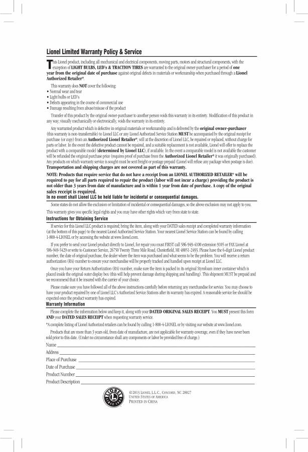
Lionel Limited Warranty Policy & Service
This Lionel product, including all mechanical and electrical components, moving parts, motors and structural components, with the exception of LIGHT BULBS, LED’s & TRACTION TIRES are warranted to the original owner-purchaser for a period of one
year from the original date of purchase against original defects in materials or workmanship when purchased through a Lionel Authorized Retailer*.
This warranty does NOT cover the following:• Normal wear and tear• Light bulbs or LED’s• Defects appearing in the course of commercial use• Damage resulting from abuse/misuse of the product
Transfer of this product by the original owner-purchaser to another person voids this warranty in its entirety. Modification of this product in any way; visually mechanically or electronically, voids the warranty in its entirety.
Any warranted product which is defective in original materials or workmanship and is delivered by the original owner-purchaser (this warranty is non-transferrable) to Lionel LLC or any Lionel Authorized Service Station MUST be accompanied by the original receipt for purchase (or copy) from an Authorized Lionel Retailer*, will at the discretion of Lionel LLC, be repaired or replaced, without charge for parts or labor. In the event the defective product cannot be repaired, and a suitable replacement is not available, Lionel will offer to replace the product with a comparable model (determined by Lionel LLC), if available. In the event a comparable model is not available the customer will be refunded the original purchase price (requires proof of purchase from the Authorized Lionel Retailer* it was originally purchased). Any products on which warranty service is sought must be sent freight or postage prepaid (Lionel will refuse any package when postage is due). Transportation and shipping charges are not covered as part of this warranty.
NOTE: Products that require service that do not have a receipt from an LIONEL AUTHORIZED RETAILER* will be required to pay for all parts required to repair the product (labor will not incur a charge) providing the product is not older than 3 years from date of manufacture and is within 1 year from date of purchase. A copy of the original sales receipt is required.In no event shall Lionel LLC be held liable for incidental or consequential damages. Some states do not allow the exclusion or limitation of incidental or consequential damages, so the above exclusion may not apply to you.
This warranty gives you specific legal rights and you may have other rights which vary from state to state.Instructions for Obtaining Service If service for this Lionel LLC product is required; bring the item, along with your DATED sales receipt and completed warranty information (at the bottom of this page) to the nearest Lionel Authorized Service Station. Your nearest Lionel Service Station can be found by calling 1-800-4-LIONEL or by accessing the website at www.lionel.com.
If you prefer to send your Lionel product directly to Lionel, for repair you must FIRST call 586-949-4100 extension 9105 or FAX Lionel at 586-949-5429 or write to Customer Service, 26750 Twenty Three Mile Road, Chesterfield, MI 48051-2493. Please have the 6-digit Lionel product number, the date of original purchase, the dealer where the item was purchased and what seems to be the problem. You will receive a return authorization (RA) number to ensure your merchandise will be properly tracked and handled upon receipt at Lionel LLC.
Once you have your Return Authorization (RA) number, make sure the item is packed in its original Styrofoam inner container which is placed inside the original outer display box (this will help prevent damage during shipping and handling). This shipment MUST be prepaid and we recommend that it be insured with the carrier of your choice.
Please make sure you have followed all of the above instructions carefully before returning any merchandise for service. You may choose to have your product repaired by one of Lionel LLC’s Authorized Service Stations after its warranty has expired. A reasonable service fee should be expected once the product warranty has expired.Warranty Information Please complete the information below and keep it, along with your DATED ORIGINAL SALES RECEIPT. You MUST present this form AND your DATED SALES RECEIPT when requesting warranty service.
*A complete listing of Lionel Authorized retailers can be found by calling 1-800-4-LIONEL or by visiting our website at www.lionel.com.
Products that are more than 3 years old, from date of manufacture, are not applicable for warranty coverage, even if they have never been sold prior to this date. (Under no circumstance shall any components or labor be provided free of charge.)
Name _________________________________________________________________________Address ________________________________________________________________________Place of Purchase _________________________________________________________________Date of Purchase __________________________________________________________________Product Number __________________________________________________________________Product Description ________________________________________________________________