Always. Reliable. Tight. - Hauff Technik
12
www.hauff-technik.de CABLE ENTRIES AND EARTHINGS SECONDARY SUBSTATIONS AND INDUSTRIALLY MANUFACTURED TECHNICAL BUILDINGS Always. Reliable. Tight.
Transcript of Always. Reliable. Tight. - Hauff Technik

www.hauff-technik.de
CABLE ENTRIES AND EARTHINGS
SECONDARY SUBSTATIONS AND INDUSTRIALLY MANUFACTURED TECHNICAL BUILDINGS
Always. Reliable. Tight.

2
Secondary substations and industrially manufactured technical buildings
CABLE ENTRIES
Secondary substations are a fundamental part of the power network and the energy distribution system. To ensure fault-free operation and high service security in the long term, secondary substations must be equipped with appro-priate technology – some of which is very sensitive – to protect against hazards. Cable entries play an important role here.
In Germany, secondary substations must fulfi ll a range of requirements, including:• DIN VDE 0101 (facilities over 1000 V)
For prefabricated substations:• DIN 62271-202 (high-voltage switchgear and controlgear part 202:
high voltage/low voltage prefabricated substation)
No moisture in the substationA sealed cable entry prevents water and moisture from entering the substation building. This means that the technical equipment is protected against corrosion and the operational safety is increased at the same time.
No rodents or reptilesThe seal has an additional protective function: no rodents or reptiles can reach the inside of the substation, unlike with non-sealed openings. As a result, damage caused by rodents, especially short circuits and power failures, can be avoided.
No oil leakage into the ground water and soilThe German Water Resources Act (WHG) stipulates that, when dealing with water pollutants including transformer oil, facilities should be constructed and operated in such a way that there is no risk of them having a negative impact on the properties of water areas. The absolute leak-tightness of a cable entry contributes a great deal to ensuring compliance with this requirement. In the event of damage, a cable entry holds back escaping transformer oil and prevents it from entering the soil or ground water.
YOUR ADVANTAGES
HAUFF-TECHNIK
Hauff-Technik is one of Europe’s leading manufacturers of cable, pipe and building entries. We have specialised in sealing cables in substations for the last 60 years. Our innovations protect nearly all types of buildings from gas, penetrating water, dirt and vermin. Hauff-Technik is setting standards in the energy supply sector with products such as cable entries for secondary substations.

3
Secondary substations and industrially manufactured engineering buildings
EARTHINGS
REQUIRED EARTHINGS
The earthing incorporates all of the measures required for connecting an electrical part with the earth. It is an essential component in secondary substations, switch gears, substations, etc. There is a difference between protective, functional, operational and lightning-protection earthings:
HEA-IS-M 12 earthing entry: a flat steel connection via the Z-KG-M 12 cross-clamp on one side and an earthing conductor connection via the Z-B-M 12 connection bolt on the other side.
• With the protective earthing, a safe connection with the ground is created in order to protect people (and animals) against dangerously high touch voltages in the event of an error. The requirements for the equipotential bonding are described precisely in the VDE 0100-540 standard; the corresponding guidelines for the foundation earth electrode can be found in DIN 18014.
• The functional earthing is used to ensure that electrical equipment in the substation can be operated safely. With the functional earthing, fault currents should be diverted safely.
OUR SOLUTIONS
With earthing entries and earthing fixed points from Hauff-Technik, earthing conductors can be fed through the substation walls in a safe and leak-tight manner or connected to the reinforcement. The connection thread (M12 or M16) can be used to connect round or flat steels/ring earth electrodes with connection bolts, cable shoes or lugs, or with cross-clamps.
The HEA-IS-M12/X insulated earthing entry from Hauff-Technik is particularly suited to substation construction and is used for various functions, including as an optional test isolating joint for the earthing system. The function of the ring earth electrode can be tested separately outside the substation using the insulated earthing entry.
When feeding the inner earthing to the external earthing system, country-specific requirements must be observed. Our wide range of products provides tried-and-tested solutions for all kinds of applications. Please contact us about your application.
• In switch gears, an operational earthing is primarily used to ensure that the system operates without any faults. The EN 50522 (VDE 0101-2):2011-11 standard provides exact specifications on protecting the system against short circuits above 1 KV (max. temperature and no damage on the connection and on the concrete structure).
• With the lightning-protection earthing, lightning currents should be safely diverted into the ground to protect people, animals and buildings. The requirements are regulated in EN 62305-3 (VDE 0185-305-3):2011-10.
4
Example
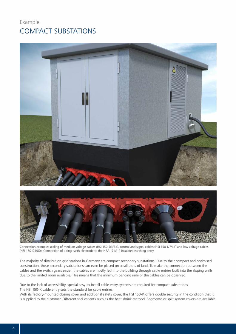
COMPACT SUBSTATIONS
The majority of distribution grid stations in Germany are compact secondary substations. Due to their compact and optimised construction, these secondary substations can even be placed on small plots of land. To make the connection between the cables and the switch gears easier, the cables are mostly fed into the building through cable entries built into the sloping walls due to the limited room available. This means that the minimum bending radii of the cables can be observed.
Due to the lack of accessibility, special easy-to-install cable entry systems are required for compact substations. The HSI 150-K cable entry sets the standard for cable entries. With its factory-mounted closing cover and additional safety cover, the HSI 150-K offers double security in the condition that it is supplied to the customer. Different seal variants such as the heat shrink method, Segmento or split system covers are available.
Connection example: sealing of medium voltage cables (HSI 150-D3/58), control and signal cables (HSI 150-D7/33) and low voltage cables (HSI 150-D1/80). Connection of a ring earth electrode to the HEA-IS-M12 insulated earthing entry.

5
Example
WALK-IN SUBSTATIONS
Walk-in secondary substations have the advantage that the system can be operated and maintained from within the building and is therefore not dependent on the weather. There are numerous installation possibilities for walk-in substation buildings. As a result, transformers, switch gears, inverters, registers and measuring devices can be integrated. Substations are generally installed above ground, but can also be built into slopes or installed underground depending on the requirements.
The HSI 150 cable entry sets the standard here with the HSI 150-K single wall insert and the HSI 150-K2 double wall insert. With the HSI 150-K2 double wall insert, which is available for wall thicknesses from 100 mm, cables can be sealed and, in addition, cable ducts can be connected in a pressure-tight manner. Seal variants such as the heat shrink method, split system covers and Segmento are available for sealing cables. It is possible to connect smooth and corrugated cable ducts as well as the flexible KES-M 150 cable entry system. Using a duct connection means that additional civil engineering works directly in front of the building are not required when replacing lines or laying new ones, which also means that possible damage to the cables is avoided.
Different solutions for sealing cables and connecting protective pipes in walk-in secondary substations.

6
Cable entries HSI 150
WALL INSERTS AND PLASTIC FLANGE
Neben der Kabeldurchführung HSI 150 gibt es das kleinere System HSI 90 mit verschiedenen Systemdeckeln für die Kabelabdich-tung bzw. Rohranbindung.
HSI 150-K/X single wall insert – one-sided connection on the building exterior
The single wall inserts are the preferred method of cable sealing in compact substations. The minimum wall thickness is 70 mm. Along with the pressure-tight closing cover, single wall inserts are equipped with a safety cover, which is only removed immediately before laying the cable. This double security also prevents water from entering if the closing cover is opened accidentally.
HSI 150-K2/X double wall insert – connections on both sides for cable ducts and cables
Double wall inserts are the preferred method of cable sealing in walk-in substations. The minimum wall thickness is 100 mm. They are equipped ex-works with pressure-tight closing covers with the bayonet system on both sides. Double wall inserts provide the opportunity to connect cable ducts and also to seal the cable, for example.
HSI 150-GSM single wall insert with plug-in socket
The single wall insert with plug-in socket is an exceptionally economically and technically sophisticated solution for connecting smooth cable ducts in a pressure-tight manner (Ø 110, 125 or 160 mm). The HSI 150-GSM is also still pressure-tight after connecting the cable duct thanks to the closing cover that is preinstalled at the factory. After the cable has been laid, it is preferably sealed with split system seals on the inside of the building.
HSI 150-DFK plastic fl ange for retrofi tting on sheet steel, sheet metal casings or concreted walls
The leak-tight connection to the wall is achieved using a 6-mm-thick surface seal made of EPDM. The fastening elements are made of high quality stainless steel inclusive sealing washer. The integrated spirit level simplifi es the horizontal adjustment. All system covers and system seals from the HSI 150 range can be installed.
BD 90 or BD 68 site power supply entry for a temporary power supply
With the site power supply entry, cables can be temporarily fed into the substation above ground.This means that the doors of the substation can be closed. When not being used, the site power supply entry is sealed on both sides with screw caps. On the inside of the substation, the site power supply cover, which can be ordered as an optional extra, provides additional security against vandalism and rodents.
The HSI 150 cable entry is already embedded in concrete when manufacturing the substation building in the prefabricated part factory. Packages of any size can be formed using the square adapter base. The leak-tightness of the concrete is achieved using 3-ribbed seals made of thermoplastic elastomer (TPE). There is a seal of quality under the protective foil, which guarantees the leak-tightness of the closing cover when it is undamaged.
For sealing cables and cable ducts, there are different system covers and system seals available, which are connected via the integrated bayonet system. All cable entries are pressure tight and sealed with closing covers when supplied to the customer.
Alongside the HSI 150 cable entry, there is the smaller system, the HSI 90, with different system covers for sealing cables and connecting pipes.

7
Cable entries HSI 150
SYSTEM COVERS AND EARTHINGSSystem covers and system seals are installed in the single and double wall inserts, which have already been embedded in concrete, or in the plastic or aluminium fl anges.
HSI 150 system cover – cold shrink technology
The system covers with bayonet system are installed in the wall inserts before the cables are laid. To seal the cables, the HSI 150-D1/80, HSI 150-D3/58 and HSI 150-D7/33 system covers are available depending on the requirements. Hot or, alternatively, cold shrink sleeves are included in the scope of delivery. Empty sockets are sealed with VS blind plugs.
HSI 150-DG split system cover
The HSI 150-DG system cover is installed after the cables have been laid. This means that the entire surface of the cable entry is available when laying the cables. An adapter ring, which is also split, ensures an optimal seal. Thanks to the patented super segmented ring technology with precisely marked application ranges, the seal insert can be adjusted on site to correspond to the cables that have been laid. Four variants are available in the application range from 10 – 112 mm.
SEGMENTO for sealing control and communication cables
With Technogel, the seal material used for Segmento, cables can be sealed in a particularly gentle manner. Four segments, which can be installed in any combination in the HSI 150-S3 system cover, are available in the application range from 5 – 31 mm. Retrofi tting is very simple. All segments are supplied with blind plugs.
HSI 150-D-GSM for connecting smooth cable ducts with plug-in socket
With the system cover, smooth cable ducts with an outer diameter of 110, 125 or 160 mm can be connected. Quick and easy installation using plug-in technology.
HSI 150-M for connecting smooth or corrugated cable ducts
With the system cover, smooth or corrugated cable ducts with an outer diameter of 110, 125 or 160 mm can be connected. The pipe is connected using a fl exible and stable rubber sleeve, which is pressed against the system cover and the cable duct with stainless steel bands.
KES-M 150 cable entry system
The fl exible and robust 14150 spiral hose is connected in a gastight and watertight (2.5 bar) manner using the system cover with the rubber sleeve method. Different seal variants using the shrink- or rubber sleeve method are available.
HEA-IS-M12 insulated earthing entry
The insulated earthing entry from Hauff-Technik is particularly suited to substation construction and is used for various functions, including as an optional test isolating joint for the earthing system. The function of the ring earth electrode can be tested separately outside the substation using the insulated earthing entries. Round or fl at steels and cable shoes can be connected using cross-clamps or connection bolts. Successful short-circuit test in accordance with EN 50522 (VDE 0101-2):2011-11.
HEA-A-M12 earthing fi xed point for welding to reinforcement rods of the substation building
The earthing fi xed point for the substation construction can be used for equipotential bonding and earthing the secondary substation. The connection point of the substation earthing can be integrated internally or externally with the conductor core, which is made of corrosion-resistant stainless steel V2A (AISI 304L). The reinforcement rods can be welded without changing any material thanks to the transition weld stainless to carbon steel and the practical connection groove. Suitable for distances of 50 or 70 mm between the shuttering and reinforcement. Successful short-circuit test in accordance with DIN EN 50522 (VDE 0101-2):2011-11.

8
System cover for cables
SELECTING THE RIGHT CABLE SEAL
+ particularly well-suited
Seal variant Article codeArticle
number
Ap
plic
atio
n r
ang
e
Split
, re
tro
fi t
inst
alla
tio
n
Types of cable
Tran
sfo
rmer
oil
con
sist
ency
Med
ium
vo
ltag
e, s
ing
le w
ire
Med
ium
vo
ltag
e,
mu
ltip
le w
ires
Low
vo
ltag
e, s
ing
le w
ire
Low
vo
ltag
e,m
ult
iple
wir
es (
Pow
er c
able
)
Co
ntr
ol c
able
sFi
bre
op
tic
cab
les
Split system cover HSI 150-DG 1/70-112 21022000301x
70-112+
HSI 150-DG 1/36-70 2102200020 1x36-70 + +
HSI 150-DG 3/24-54 2102200000 3x24-54 + + + +
HSI 150-DG 6/10-36 2102200010 6x10-36 + +
System cover – heat shrink method
HSI 150-D1/80 2101100010 1x25-78 + +
HSI 150-D3/58 2101100049 3x22-56 + + + +
HSI 150-D7/33 2101100059 7x12-31 + +
SEGMENTO system cover
SEG 2/31 2300130000 2x20-31 +
SEG 3/26 2300140000 3x20-26 +
SEG 6/21 2300150000 6x15-21 +
SEG 8/15 2300160000 8x5-15 +

9
Special solutions
FOR SPECIAL REQUIREMENTS
SLANTED ENTRIES
Slanted wall inserts are available for 30, 45 and 60° angles and are supplied ready for installation flush with the formwork.
Slanted entries are used, for example, for substations integra-ted into the basement of buildings or in rooms where there is limited space. Thanks to the slanted entry of the cables through the wall, the cables can be laid and connected in accordance with the minimum bending radii.
DUCT CONNECTIONS
Cable entries with an duct connection have the advantage that the cable can be laid and replaced at any time without civil engineering works. Empty pipe connections are particularly sensible if the entries are very deep or inaccessible, lots of cables are laid in a confined space (e.g. in front of electrical rooms) or when the cables have a low level of covering after refill as mechanical protection.
The KES-M 150 cable entry system from Hauff-Technik is gas- and watertight up to 2.5 bar and can be made up individually in different lengths and with different cable seal variants.
For (customer-owned) substations that are integrated in buildings without a basement, the cables must sometimes be inserted through the base plate. Gas- and watertight solutions are also required here. The flexible and mechanically stable spiral hose 14150 with a smooth inner surface, in conjunction with the KES-M 150 connection components, is ideally suited to the construction of duct systems under the base plate.
SOLUTIONS FOR ELEMENT WALLS
Double walls/element walls are a special case with regard to sealing. Here, the element walls manufactured in the pre- fabricated parts factory are grouted on site with in-situ concrete. The multi-layered, non-monolithic wall structure of the double element wall requires water barriers in both the prefabricated parts and the in-situ concrete.
Hauff-Technik provides different solutions for cable and earthing entries here – they are always recognisable by the three 3-ribbed seals made of TPE (thermoplastic elastomer).
HSI 150-K2/X double wall insert, HSI 150-D7/33 system cover, KES-M 150-D pipe connection with sleeve and spiral hose 14150
HSI 150-K2 S45°/X slanted wall insert and HSI 150-D3/58 system cover
Infinitely adjustable to the required wall thickness. Cable entry HSI 150-K2-Varia for element walls.

10
Always. Safe. Mounted.
INSTALLATION INSTRUCTIONS
IMPACT OF MECHANICAL FORCES
No forces must act on the cable entries via the cables and ducts as these are designed purely to seal and not to absorb forces. Any forces that do occur must be absorbed by appropriate equipment. Another important aspect is the correct compaction when filling in the cable trench or the duct route. Settlement of the ground must be avoided or appropriate measure must be taken.
CENTERING THE CABLES
The cables are centered in the system cover socket with the help of the HSI-ZB centering tape. The smaller the cable diameter is compared to the socket, the more important this is. Centering creates the optimal conditions for the best shrinking results from the socket to the cable. In addition, the cable is protected against pressure by the edges of the system cover.
SPACER FOR PACKAGING
The HSI-AH 40 spacer increases the centre distances between the wall inserts by 40 mm to a total of 250 mm. Thanks to the increased spacing, a better filling quality is achieved when compacting the cable duct route in layers.
You can find more information about our products at www.hauff-technik.de

11
Always. Safe. Tested.
TEST REPORTS
TEST TEST INSTITUTE/APPROVAL BODY
TEST REPORT/APPROVAL NO.
Test of the gastightness of the HSI 150-DG-3/24-54 system cover for building entries using compressed air 2.5 bar
KIWA MPA Bautest GmbH A 9040-1/2012
Test of the gastightness of the HSI 150-DG-6/10-36 system cover for building entries using compressed air 2.5 bar
KIWA MPA Bautest GmbH A 9040-2/2012
Test of the watertightness of the HSI 150-DFK sealing system with D3/58 system cover for building entries 2.5 bar
KIWA MPA Bautest GmbH A 9091-1/2010
Test of the watertightness of a cable entry system 150 and integrated HSI 150-D3/58 system cover 2.5 bar
KIWA MPA Bautest GmbH A 9072-5/2009
Test of the watertightness of a sealing system HSI 150 system with integrated HSI 150-D blind cover 2.5 bar
KIWA MPA Bautest GmbH A 9072-3/2009
Test of the oil tightness over 90 days with the seal inserts and concrete built-in parts: • HEA-IS-M12/100• HSI 150-DG• HSI 150-K/100 with HSI 150-D• HSI 150-D3/58 with VS 58/60, thermo and cold shrink sleeve
in HSI 150-K/100• HSI 150-K2/100 with HRD 150/160-G-3/20 (NBR)• HSI 150-K2/100 with HSI 150-D• Sikaflex-Tank N sealing compound
KIWA MPA Bautest GmbH A 9071-1/2011
Short-circuit test HEA-IS-M12/120, M12 cable shoe direct connection, Z-KG-M12 fvz to 10 kA /1s
RWE Eurotest 11-175-1
Short-circuit test HEA-IS-M12/120 with Z-KG-M12-V4A (AISI 316L) cross-clamp with 4.9 kA/1s
RWE Eurotest 13_311-2
Short-circuit test HEA-A-M12/50 with 6.5 kA/1s with RD 10 round steel or with 7.7 kA/1s with RD 12 round steel
RWE Eurotest 13_311-1
Please do not hesitate to ask if you would like to see the full test reports and approvals for our products.

Hauff-Technik GmbH & Co. KG
Robert-Bosch-Straße 989568 Hermaringen, GERMANY
Tel. +49 7322 1333-0Fax +49 7322 1333-999
www.hauff-technik.de
The
info
rmat
ion
in t
his
pu
blic
atio
n r
epre
sen
ts o
ur
curr
ent
stat
e o
f te
chn
ical
kn
ow
led
ge
and
exp
erie
nce
. Ho
wev
er, g
iven
th
e m
ult
itu
de
of
po
ssib
le in
flu
ence
s af
fect
ing
th
e p
roce
ssin
g a
nd
use
of
ou
r p
rod
uct
s, t
his
info
rmat
ion
do
es n
ot
exem
pt
pro
cess
ors
an
d u
sers
fro
m r
un
nin
g
thei
r o
wn
tes
ts a
nd
tri
als.
We
will
rep
lace
an
y p
arts
th
at c
ann
ot
be
use
d d
ue
to d
efec
tive
mat
eria
ls. W
e d
o n
ot
rep
lace
par
ts f
or
def
ects
cau
sed
du
e to
tra
nsp
ort
, sto
rag
e o
r fa
ult
y in
stal
lati
on
an
d t
he
con
seq
uen
ces
ther
eof.
All
info
rmat
ion
wit
ho
ut
gu
aran
tee.
traf
ost
atio
n_e
n_1
8073
1