Aluminum Structural Plate
20
1 Aluminum Structural Plate ENGINEERED SOLUTIONS
Transcript of Aluminum Structural Plate

1
Aluminum Structural Plate
ENGINEERED SOLUTIONS

2
Time-Tested & DurableEngineers, officials and contractors know that proper construction materials play an important part in designing efficient, economical drainage structures. This is why corrugated metal pipe has gained wide acceptance during more than 80 years of use in drainage structures under highways, railroads, airports and city streets.
Corrugated metal pipe offers definite advantages over other materials because of its lightweight, durability, ease of installation, low maintenance and adaptability to various field conditions. Logically, engineers wanted these advantages for larger waterways but were handicapped by the limitations of handling and shipping pipe in large diameters.
Large Aluminum StructuresContech pioneered steel MULTI-PLATE® structures more than 50 years ago, providing a wider range of sizes and shapes while retaining the advantages of smaller, corrugated metal pipe.
Today, Contech also manufactures an aluminum structural plate that is durable, lightweight and easy to install. There are no forms to set or remove. No curing time is needed. Large installation crews are not necessary. No special lifting equipment is needed for small structures.
Aluminum structural plates are corrugated, curved and bolt-hole punched at the plant. Reinforcing ribs (if required by design) are also curved and bolt-hole punched to match the plate fabrication. Delivered to the job site unassembled, the plates and ribs are easily bolted together to form various shapes: round, vertical and horizontal ellipse, pipe=arch, underpass and arch.
Evidence of their dependability and economy is presented by the thousands of aluminum structural plate structures that have been installed since 1964.
Applications:
• Smallbridges• Culverts• Streamenclosures• Stormsewers• Gradeseparations• Conveyorcovers• Pedestrian,livestockandvehicularunderpasses• Conduits• Aggregatereclaimtunnels• Storagedomesandmagazines• Liningformasonryorconcreteconduits
.
Advantages for Bridge Replacements• Durable• Corrosionresistant• Abrasionresistant• Lightweight• Reducedinstallandmaintenancecosts• Easysite-adaptability• Modularbridgedesign
Corrosion ResistantThe aluminum allows in aluminum structural plate have a proven history of excellent corrosion resistance. This is primarily due to a thin, tenacious, inert oxide barrier that forms on the metal surface when exposed to air.
The tough, tightly adhering oxide barrier cannot be easily removed. If damaged or affected by an aggressive environment, this oxide barrier will reform. This is referred to as a “self-healing” effect. The oxide barrier appears on the structure surface as a grayish-white coating that will build up over time.
Service-life expectancy studies on installed aluminum drainage products have been conducted since the early 1960s by state and federal agencies.
Based upon the performance and ongoing inspection of aluminum drainage structures first installed in 1959, a minimum service life of 75 years can be predicted for .10”-thick aluminum structural plate (pH between 4.0 to 9.0 and resistivity > 500 ohm-cm). In addition, good performance may be expected in seawater environments when the structure is backfilled with a clean, granular materials.
All metal attachments such as rebar and anchor bolts and rods should be galvanized (no black steel should be in contact with the aluminum structures). Galvanized fasteners have proven to be completely compatible with aluminum structural plate. Your Contech representative can provide additional information on this subject.
Aluminum Structural Plate

3
Abrasion ResistantAluminum’s abrasion resistance has been proven through years of exposure to wet/dry abrasion-corrosion cycles. In normally abrasive runoffs, aluminum will only peen with minimum metal loss.
The Aluminum Association presented a paper to the Transportation Research Board in January 1969, reporting on more than 1,000 aluminum culverts*. (An updated report was presented in 1986**.)
Both reports included a method of predicting abrasion performance of aluminum corrugated drainage pipe, whereby peak energy curves were converted into a service-life chart. If required, the service life of structural plate can be extended by increasing the metal thickness of the structure and /or its invert.
If a proposed structure is expected to be installed in a stream with high-velocity runoff and with heavy bed load (especially angular rocks with sharp corners), it is recommended that the Aluminum Association abrasion papers be reviewed. Copies are available form Contech on request. When highly abrasive conditions are anticipated, it may also prove desirable to use arch structures on concrete fittings and remove any concern of invert damage.
* “TheMechanismsofAbrasionofAluminumAlloyCulvert,RelatedFieldExperiencesandaMethodtoPredictCulvertPerformance”
** “AbrasionResistanceofAluminumCulvertBasedonLong-TermFieldPerformance”
Durability
This aluminum structural plate pipe has handled tidal ocean waters under U.S. Highway 1 at the Bay of Fundy in Maine since 1966.
The interior of this deteriorating stone arch bridge was relined with aluminum structural plate.

4
LightweightLightweight is one of the main advantages of aluminum drainage structures. Aluminum structural plate weighs approximately 1/50 as much as reinforced concrete pipe in an equivalent size. This weight factor reduces assembly and equipment costs, helps gain access to remote sites and allows handling of long preassembled structures with relative ease.
Reduced Install CostsUnloading – Lightweight plates and reinforcing ribs arrive at the job site in strapped and nested bundles. Individual plates and ribs are generally light enough to be handled by one worker, and bundles can be handled with light duty lifting equipment.
Assembling – Most structures contain plate and rib sizes that be assembled without lifting equipment. As a quality assurance measure, at least one ring of plates for each order is plant-assembled and checked prior to shipment.
Aluminum structural plate can be manufactured into a large sections with up to three difference radii in the same plate. This capability reduces the number of joint connections and thus lowers assembly work hours.
Off-site assembly is an added feature of lightweight aluminum with obvious cost-savings. This can be at a remote assembly yard or alongside a ditch.
Structural DesignThe structural performance of aluminum structural plate has been proven by the thousands of installations throughout the U.S. Contech’s Aluminum structures Plate Design (tables 7-14) meets or exceeds the AASHTO Standard Specifications for Highway Bridge’s Section 12 and ASTM B 790 for HS 20 loading. Call a Contech representative for design information on HS 25 and other loadings.
Like all structures, the design of structural plate products starts with the foundations. For structures with inverts, a uniform bed must be provided by the engineer. Foundation bearing strength must be adequate to both maintain the desired finished surface grade and ensure the serviceability of pavement overlays, etc. Adjacent foundations must be able to support the heavier structure sidefills so as not to settle relative to the structure. Inadequate foundation material should be replaced.
For backfill requirements see the Installation Section on Page 19. For near minimum cover structures, the roadway surface must be maintained to ensure proper cover (see HO Tables on Pages 12-15 for allowable minimum and maximum covers)
Boxed CulvertsA ribbed, corrugated aluminum box culvert structure is a specially designed aluminum structural plate product that has a wide span and a low rise needed for a low headroom, low cover installation.
Contech’s box culverts combine the low profile shape of rigid box culverts with the strength and economies of flexible structures . Contech Aluminum Box Culverts are available in a wide range of standard sizes (8’9” x 2’6” to 35’3” x 13’7”) and components that permit a minimum cover of 1.4’ (17”) for all spans.
Long Span StructuresLong span designs add both longitudinal stiffeners (thrust beams) and circumferential stiffeners (reinforcing ribs) to conventional aluminum structural plate to achieve larger sizes. Clear spans in excess of 30’ and clear areas over 435 sf are achievable with long spans.
Available shapes include low profile and high profile arch horizontal ellipses. Long span structures are particularly suited for applications that require relatively low, wide openings. Heights of cover are general limited to 15’.
Standard Specifications:
• AASHTOM219andASTMB746–conduit,pipe• ASTMB209–material• ASTMB789–installation• ASTMB790–design• AASHTOStandardBridgeDesignSpecificationsSection12–design
• AREMA-ManualforRailwayEngineering,Chapter1,Part4• ASTMB864–boxculverts
Handling & Design

5
End TreatmentProper end treatments perform both structural and hydraulic functions.
Standard end finishes available on aluminum structural plate are square ends, step bevels, skews, partial bevels, and skew bevels.
Uncut or square-end structures are the lowest in cost and are readily adaptable to road widening projects. When skewed to the roadway embankment, larger structures may require properly warped and balanced backfill to provide uniform soil loading and support perpendicular to the structure’s center line.
For hydraulic structures, special attention should be given to proper reinforcement of the metal edges on the cut ends of a structure to secure them against hydraulic forces. The cut ends of a structure are no longer supported by a full ring and are less stiff than the barrel of the structure. Extreme cut ends should be avoided on any structure. Cut ends on larger structures are no longer supported by a full ring and are less stiff than the barrel of the structure. Extreme cut ends should be avoided on any structure. Cut ends on larger structures should be anchored to a reinforce concrete collar or headwall. If beveling necessary, step bevels are recommended over other designs. Care should be used when placing backfill around cut ends to avoid distortion.
Pipe-arches are especially susceptible to hydraulic forces.
Structures designed to flow under pressure head are more vulnerable to end problems than those designed to flow less than full.
By decreasing the water infiltration under and beside the structure, hydraulic uplift (pore pressure) forces can be reduced. Full or partial reinforced concrete headwalls, grouted riprap, riprap with a geotextile and cutoff walls below and beside the structure are some of the end treatment methods that have been used to prevent uplift of the structure and control scouring of the backfill embankment.
Headwalls or other end treatments should be designed by a qualified engineer.
Appropriate end treatment design is beyond the scope of this brochure. Additional information can be obtained from the local DOT guidelines, the FHWA Circular Memo, “Plans for Culvert Inlet and Outlet Structures,” Sheets G-39-66 to G-44-66, 1966 and chapters within the AISA Handbook of Steel Drainage & Highway Construction Products.
Hydraulic NomographsHydraulic design nomographs for inlet and outlet control conditions have been developed by Dr. James R. Barton and Dr. A. Woodruff Miller, civil engineering professors at Brigham Young University, Provo, Utah.
They are based on research reports by John L. French and H.G. Bossy and are similar to nomographs found in FHWA Hydraulic Design Series #5. These nomographs and other hydraulic data may be obtained from any Contech Office listed on the back cover.
End Treatment

6
DescriptionAluminum structural plate’s corrugation pattern has a 9” pitch and a 2 ½” depth. The corrugations are at right angles to the length of the structure.
Thickness – Nominal plate thicknesses are available from 0.125” to 0.250” (See Table 12).
Lengths – Individual circumferential plate lengths are noted in terms of N (N = 9.625” or 9 5/8” or 3 pi). Standard plates are fabricated in seven net covering lengths:
• 8N(77.00”),9N(86.63”)• 10N(96.25”),11N(105.88”)• 12N(115.50”(,13N(125.13”)and14N(134.75”)
The N nomenclature translates circumference directly into nominal diameter in inches. For example, two 10N plates give a diameter of 60” (2 x 10N x 3 pi); three 12N plates = 108” (3 x 12N x 3 pi), etc. Various plates lengths structure shape and size.
Widths – All standard plates have a net width of 4’-6” centers provide a standard 5.33 bolts per foot of longitudinal seam in two parallel rows at 1 ¾ centers.
The outside crests of the end corrugations are punched for circumferential seam holes on centers of 9.625” (or 3 pi).
Material – Plates are fabricated from an aluminum allow with material properties that conform to AASHTO M219 and ASTM B 209 specifications.
Bolts and NutsHot-dipped galvanized, specially heat-treated ¾” diameter steel bolts, meeting ASTM A 307 specifications, are used to assemble structural plate sections. The underside of the bolt head is uniformly rounded and does not require special positioning.
In addition, the underside of the bolt head is ribbed to prevent bolt rotation while tightening. Unlike conventional bolts, once the nut is finger tight, final tightening can usually be accomplished by one worker.
Plate Data

7
Round and Vertical & Horizontal Ellipse
Notes1.N=9.625”2.Dimensionsaretoinsidecorrugationcrestsandaresubjecttomanufacturingtolerances.
3.Todeterminethepropergage,useinformationontable7.4.Reinforcingriblength,ifrequired.For66”through96”diameter,useTypeIIribonly.
5.Areasasshownareforroundpipe.Areasforverticalellipsesareslightlyless.
Notes1.N=9.625”2.Dimensionsaretoinsidecorrugationcrestsandaresubjecttomanufacturingtolerances.
3.Reinforcingriblength,ifrequired.4.Todeterminethepropergage,useinformationontable9.
This front end loader easily handles this 50’ section of round pipe.
8
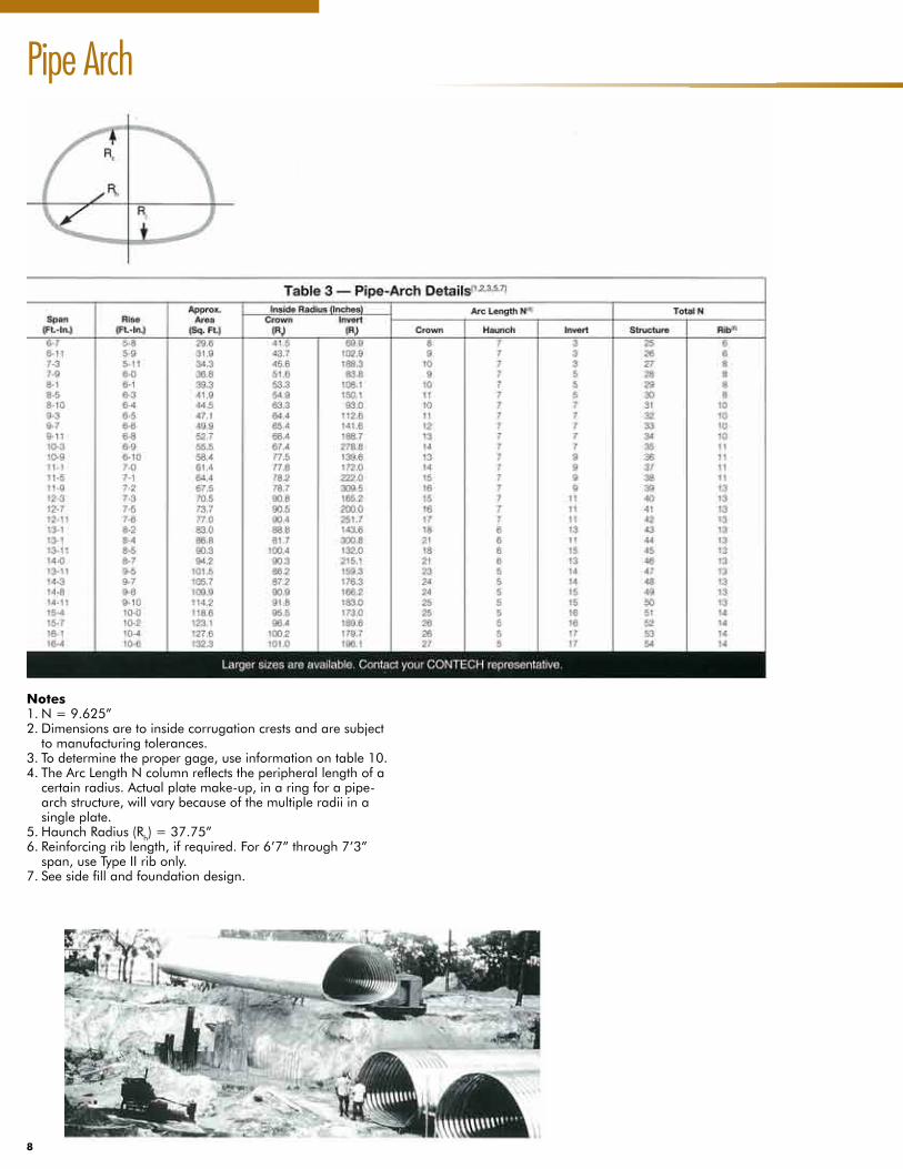
Pipe Arch
Notes1.N=9.625”2.Dimensionsaretoinsidecorrugationcrestsandaresubjecttomanufacturingtolerances.
3.Todeterminethepropergage,useinformationontable10.4.TheArcLengthNcolumnreflectstheperipherallengthofacertainradius.Actualplatemake-up,inaringforapipe-archstructure,willvarybecauseofthemultipleradiiinasingleplate.
5.HaunchRadius(Rh)=37.75”6.Reinforcingriblength,ifrequired.For6’7”through7’3”span,useTypeIIribonly.
7.Seesidefillandfoundationdesign.

9
Underpass
Notes1.N=9.625”2.Dimensionsaretoinsidecorrugationcrestsandaresubjecttomanufacturingtolerances.Thedesignershouldallowsufficientclearanceformanufacturingtolerancesandinstallationdeflection.
3.Todeterminepropergage,useinformationontable11.4.TheArcLengthNorinchescolumnreflectstheperipherallengthofacertainradius.Actualplatemake-up,inaringforanunderpassstructure,willvarybecauseofmultipleradiiinasingleplate.
5.Thebottomsofpedestrian/animalunderpassesarenearlyflat.6.Reinforcingriblength,ifrequired.OnlyTypeIIcrownribscanbeusedonapedestrian/animalunderpasses.
7.Seesidefillandfoundationdesign.
10
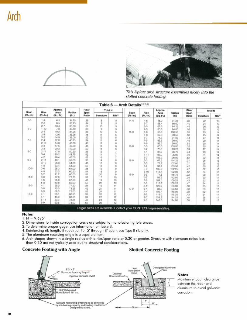
Arch
Notes1.N=9.625”2.Dimensionstoinsidecorrugationcrestsaresubjecttomanufacturingtolerances.3.Todeterminepropergage,useinformationontable8.4.Reinforcingriblength,ifrequired.For5’through8’span,useTypeIIribonly.5.Thealuminumreceivingangleisaseparateitem.6.Archshapesshowninasingleradiuswitharise/spanratioof0.30orgreater.Structurewithrise/spanratioslessthan0.30arenottypicallyusedduetostructuralconsiderations.
NotesMaintain enough clearance between the rebar and aluminum to avoid galvanic corrosion.
90° Aluminum Receiving Angle (5)

11
Offering Superior Corrosion Resistance and Many Decades of
Maintenance-Free Service Life.

12
Height of Cover
90° Aluminum Receiving Angle (5)
Aluminum structural plate structures offer superior corrosion resistance and many decades of maintenance-free service life.

13
Notes
1.Thetablesarepresentedforthedesigner’sconvenienceinselectingmetalthickness,reinforcingribtypeandribspacingforminimumcoverapplications.Forstructureswithmaximumcoversgreaterthanthoseshowninthetable,heavierplatemaypossiblybeused.ConsultyourContechrepresentative.
2.Allowablecover(minimumandmaximum)ismeasuredfromtheoutsidevalleyofthecrownplatetothetopofrigidpavement.Minimumcoverismeasuredatthelowestfillareasubjectedtopossiblewheelloads(typicallyattheroadwayshoulder).Minimumcovermustbemaintainedinunpavedareas.Maximumcoverismeasuredatthehighestfilland/orthehighestpavementelevation.
3.Tofindtheminimummaterialsrequirementsforthealuminumstructuralplatestructure.a.Designspecifications:Section12ofAASHTO’sStandardSpecificationsforHighwayBridgesandASTMB790.
b.StandardHS20wheelloads.ConsultaContechrepresentativeforspecialloadingconditions.
c.AASHTOM145backfillmaterialsclassifiedasA-1,A-2orA-3compactedto90%densityperAASHTOT99.Unitweightofsoil:120lb/cf
d.Yieldpointofaluminum:24,000psiforplate,35,000psiforreinforcingribs.

14
Height of Cover
Notes: Maximum cover based on allowable corner bearing pressure of approximately 4,000 psi (2 tsf).
Notes: Maximum cover based on allowable corner bearing pressure of approximately 4,000 psi (2 tsf).

15
Notes: Maximum cover based on allowable corner bearing pressure of approximately 4,000 psi (2 tsf).
Notes
1.Thetablesarepresentedforthedesigner’sconvenienceinselectingmetalthickness,reinforcingribtype,andribspacingforminimumcoverapplications.Forstructureswithmaximumcoversgreaterthanthoseshowninthetable,heavierplatemaypossiblybeused.CallyourContechRepresentative.
2.Allowablecover(minimumandmaximum)ismeasuredfromtheoutsidevalleyofthecrownplatetothebottomofflexiblepavementorfromtheoutsidevalleyofthecrownplatetothetopofrigidpavement
3.Tofindtheminimummaterialsrequirementsforthealuminumstructuralplatestructure.a.Designspecifications:Section12ofAASHTO’sStandardSpecificationsforHighwayBridgesandASTMB790.b.StandardHS20wheelloads.ConsultaContechrepresentativeforspecialloadingconditions.c.AASHTOM145backfillmaterialsclassifiedasA-1,A-2orA-3compactedto90%densityperAASHTOT99.Unitweightofsoil:120lb/cf
d.Yieldpointofaluminum:24,000psiforplate,35,000psiforreinforcingribs.

16
Handling Weight

17
Reinforcing Rib DesignWhen circumferential ribs are used with aluminum structural plate, they are reinforce the structure to reduce minimum cover and provide added stiffness. These circumferential ribs are bolted to the structure’s crown at spacing of 9”, 18”, 27”: or 54” centers.
The socket is specially shaped to fit around the top “bulb” of the reinforcing rib. This is a six-point socket for 1-1/4” nuts and with a 3/4” drive. This socket will work on both Type II and Type IV ribs. Contech offers this socket as a construction aid. Notes
1.Boltsandnutsareincludedinthecolumntitled“WeightperFt.(Lb.)”
2.Seetable12forthehandlingweightofastructurewithoutribs.
3.ForTotalNofribonastructure,seetables1and6.

18
Specification
ScopeThis specification covers the manufacture and installation of the aluminum structural plate structure detailed in the plans.
MaterialThe aluminum structural plate structure shall consist of plates and appurtenant items as shown on the plans and shall conform to the requirements of the AASHTO M219 and ASTM B 746. The corrugated plate (and ribs if required) shall be curved and bolt hole punched at the plant. Plate thickness and rib spacings shall be as indicated on the site plans.
Bolts and nuts shall conform to the requirements of ASTM A 307 or ASTM A 449 and shall be galvanized in accordance with ASTM A 153.
Assembly The structure shall be assembled in accordance with the shop drawings provided by the manufacturer and per the manufacturer’s recommendations. Bolts shall be tightened using an applied torque of between 100 and 150 foot pounds.
InstallationThe structure shall be installed in accordance with the plans and specifications, the manufacturer’s recommendations, and the AASHTO Standard Specification for Highway Bridges, Section 26 (Division II).
BeddingThe bedding should be constructed to a uniform line and grade using material outlined in the back fill section. The foundation and haunch support areas must be capable of providing a bearing capacity of at least two tons per square foot.
BackfillThe structure shall be backfilled using clean, well-graded granular material that meets the requirements of AASHTO M145 for soil classifications A-1, A-2 or A-3. Backfill must be placed symmetrically on each side of the structure in 6” to 8” lifts. Each shall be compacted to a minimum of 90% density per AASHTO T99.
Required ElementsSatisfactory site preparation, trench excavation, bedding and backfill operations are essential to develop the strength of any flexible conduit. IN order to obtain proper strength while preventing settlement, it is necessary that the soil envelope around the structure be of good granular material, properly placed and carefully compacted.
Horizontal ellipse, pipe-arch and underpass shapes pose special installation problems not found in other shapes. These shapes will generate high corner bearing pressures against the sidefill and foundation (see the Corner Bearing Pressure equation). Therefore, special installation care must be implemented to achieve a composite aluminum/soil structure.
A qualified engineer should be engaged to design a proper foundation, adequate bedding and backfill.
Trench ExcavationIf the adjacent embankment material is structurally adequate, the trench requires only a bottom clear width of the structure’ span plus sufficient room for compaction equipment.
BeddingBedding preparation is critical to both structure performance and service life. The bed should be constructed to uniform line an grade to avoid distortions that may create undesirable stresses in the structure and/or rapid deterioration of the roadway. The bed should be free of rock formations, protruding stones, frozen lumps, roots and other foreign matter that may cause unequal settlement.
It is recommended that the bedding be a stable, well graded granular materials. Placing the structure on the bedding surface is generally accomplished by one of two methods to ensure satisfactory compaction beneath the haunches. One method is shaping the bedding surface to conform to the lower section of the structure. The other is carefully tamping a granular or select material beneath the haunches to achieve a well compacted condition.
Specification for Aluminum Structural Plate
Plates are positioned by hand are ready for assembly.
19
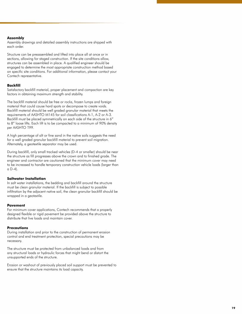
AssemblyAssembly drawings and detailed assembly instructions are shipped with each order.
Structure can be preassembled and lifted into place all at once or in sections, allowing for staged construction. If the site conditions allow, structures can be assembled in place. A qualified engineer should be engaged to determine the most appropriate construction method based on specific site conditions. For additional information, please contact your Contech representative.
BackfillSatisfactory backfill material, proper placement and compaction are key factors in obtaining maximum strength and stability.
The backfill material should be free or rocks, frozen lumps and foreign material that could cause hard spots or decompose to create voids. Backfill material should be well graded granular material that meets the requirements of AASHTO M145 for soil classifications A-1, A-2 or A-3. Backfill must be placed symmetrically on each side of the structure in 6” to 8” loose lifts. Each lift is to be compacted to a minimum of 90% density per AASHTO T99.
A high percentage of silt or fine sand in the native soils suggests the need for a well graded granular backfill material to prevent soil migration. Alternately, a geotextile separator may be used.
During backfill, only small tracked vehicles (D-4 or smaller) should be near the structure as fill progresses above the crown and to finished grade. The engineer and contractor are cautioned that the minimum cover may need to be increased to handle temporary construction vehicle loads (larger than a D-4).
Saltwater InstallationIn salt water installations, the bedding and backfill around the structure must be clean granular material. If the backfill is subject to possible infiltration by the adjacent native soil, the clean granular backfill should be wrapped in a geotextile.
PavementFor minimum cover applications, Contech recommends that a properly designed flexible or rigid pavement be provided above the structure to distribute that live loads and maintain cover.
PrecautionsDuring installation and prior to the construction of permanent erosion control and end treatment protection, special precautions may be necessary.
The structure must be protected from unbalanced loads and from any structural loads or hydraulic forces that might bend or distort the unsupported ends of the structure.
Erosion or washout of previously placed soil support must be prevented to ensure that the structure maintains its load capacity.
20
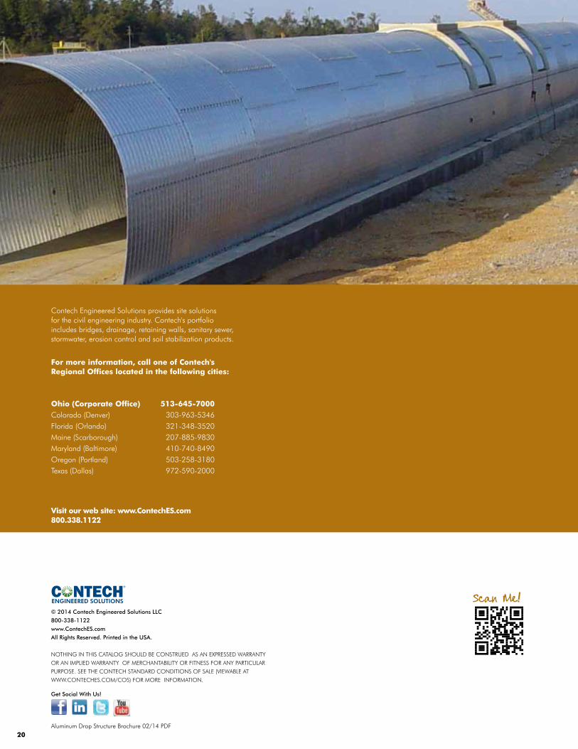
Contech Engineered Solutions provides site solutionsfor the civil engineering industry. Contech's portfolio includes bridges, drainage, retaining walls, sanitary sewer, stormwater, erosion control and soil stabilization products.
For more information, call one of Contech's Regional Offices located in the following cities:
Ohio (Corporate Office) 513-645-7000Colorado (Denver) 303-963-5346Florida (Orlando) 321-348-3520Maine (Scarborough) 207-885-9830Maryland (Baltimore) 410-740-8490Oregon (Portland) 503-258-3180Texas (Dallas) 972-590-2000
Visit our web site: www.ContechES.com800.338.1122
Aluminum Drop Structure Brochure 02/14 PDF
© 2014 Contech Engineered Solutions LLC
800-338-1122
www.ContechES.com
All Rights Reserved. Printed in the USA.
NOTHING IN THIS CATALOG SHOULD BE CONSTRUED AS AN EXPRESSED WARRANTY
OR AN IMPLIED WARRANTY OF MERCHANTABILITY OR FITNESS FOR ANY PARTICULAR
PURPOSE. SEE THE CONTECH STANDARD CONDITIONS OF SALE (VIEWABLE AT
WWW.CONTECHES.COM/COS) FOR MORE INFORMATION.
ENGINEERED SOLUTIONS
Get Social With Us!
Scan Me!